US1025876A - Control of electric motors. - Google Patents
Control of electric motors. Download PDFInfo
- Publication number
- US1025876A US1025876A US40213407A US1907402134A US1025876A US 1025876 A US1025876 A US 1025876A US 40213407 A US40213407 A US 40213407A US 1907402134 A US1907402134 A US 1907402134A US 1025876 A US1025876 A US 1025876A
- Authority
- US
- United States
- Prior art keywords
- series
- field
- shunt
- circuit
- current
- Prior art date
- Legal status (The legal status is an assumption and is not a legal conclusion. Google has not performed a legal analysis and makes no representation as to the accuracy of the status listed.)
- Expired - Lifetime
Links
- 238000004804 winding Methods 0.000 description 32
- 230000001939 inductive effect Effects 0.000 description 5
- 230000000694 effects Effects 0.000 description 4
- 230000001172 regenerating effect Effects 0.000 description 3
- 230000000979 retarding effect Effects 0.000 description 3
- XEEYBQQBJWHFJM-UHFFFAOYSA-N Iron Chemical compound [Fe] XEEYBQQBJWHFJM-UHFFFAOYSA-N 0.000 description 2
- 239000004020 conductor Substances 0.000 description 2
- 238000010586 diagram Methods 0.000 description 2
- 238000000034 method Methods 0.000 description 2
- 230000004048 modification Effects 0.000 description 2
- 238000012986 modification Methods 0.000 description 2
- 239000002253 acid Substances 0.000 description 1
- 230000003111 delayed effect Effects 0.000 description 1
- 229910052742 iron Inorganic materials 0.000 description 1
- 230000008929 regeneration Effects 0.000 description 1
- 238000011069 regeneration method Methods 0.000 description 1
- 230000003313 weakening effect Effects 0.000 description 1
Images


Classifications
-
- H—ELECTRICITY
- H02—GENERATION; CONVERSION OR DISTRIBUTION OF ELECTRIC POWER
- H02P—CONTROL OR REGULATION OF ELECTRIC MOTORS, ELECTRIC GENERATORS OR DYNAMO-ELECTRIC CONVERTERS; CONTROLLING TRANSFORMERS, REACTORS OR CHOKE COILS
- H02P7/00—Arrangements for regulating or controlling the speed or torque of electric DC motors
- H02P7/06—Arrangements for regulating or controlling the speed or torque of electric DC motors for regulating or controlling an individual DC dynamo-electric motor by varying field or armature current
- H02P7/18—Arrangements for regulating or controlling the speed or torque of electric DC motors for regulating or controlling an individual DC dynamo-electric motor by varying field or armature current by master control with auxiliary power
- H02P7/24—Arrangements for regulating or controlling the speed or torque of electric DC motors for regulating or controlling an individual DC dynamo-electric motor by varying field or armature current by master control with auxiliary power using discharge tubes or semiconductor devices
- H02P7/28—Arrangements for regulating or controlling the speed or torque of electric DC motors for regulating or controlling an individual DC dynamo-electric motor by varying field or armature current by master control with auxiliary power using discharge tubes or semiconductor devices using semiconductor devices
- H02P7/285—Arrangements for regulating or controlling the speed or torque of electric DC motors for regulating or controlling an individual DC dynamo-electric motor by varying field or armature current by master control with auxiliary power using discharge tubes or semiconductor devices using semiconductor devices controlling armature supply only
- H02P7/288—Arrangements for regulating or controlling the speed or torque of electric DC motors for regulating or controlling an individual DC dynamo-electric motor by varying field or armature current by master control with auxiliary power using discharge tubes or semiconductor devices using semiconductor devices controlling armature supply only using variable impedance
Definitions
- the chief object of the invention is to overcome the disadvantages that arise in connection with the variation of the field Strength of the motors by resistances arran 'ed in shuntrelationship with the series win in These resistances are generally non-in active and can only be made inductive to any considerable degree as compared withthe field of the motors, by employing masses of iron whose dimensions are far too great for use with electrically propelled vehicles in which undue weight or" the equipment has to be avoided.
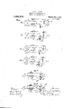
- FIG. 2 represents four stages in the change of relationship of the armatures from series-parallel to full series.
- Fig 3 and i are diagrams representing stages in the change of relationship from full series to series-- parallel and from series-parallel to full parallel respectively asapplied to series n1otors controlled by licld variation in connection with doubleseiies parallel control ill; will be unc réelleo od that in Figs, and 2 the changes are those which talre place in operating'the controller to cause a decrease in Speed of the motors 4c the changes are such as take place in increasing the speed of the motors.
- l igs, 5 and 6 are diagrams showing modifications oi the manner in which the switch herein described may be controlled. i
- a A. represent the motor a-rinatures
- B B the series field windings
- DfiD the switches for controlling the circuit of the shunt resistance
- the solenoid winding 01" and a daslrpot device P.
- the solenoid winding al is in se ries with the series field winding 18.
- the shunt field will therefore be neutralizcd, so that the electromotive force of the generating motors will be reduced and the rush of current thus minimized.
- the direction of current through the series field windings would be the same as that through the shunt field windings, and the series and shunt ampere-turns would combine to energize the field strongly.
- Fig. 5 the switch is shown as being controlled by the solenoid winding (Z in conjunction with a high resistance coil connected across the series field winding B, and wound to produce an effect opposite to that of the said solenoid winding (Z
- the voltage across the series field winding will be high and a comparatively strong current will pass through the counteracting coil aZ and thus balance the current in the solenoid coil (Z thereby preventing the switch from closing until after the current through the series field winding has reached its normal strength.
- a modification of this method of controlling the switch is shown in Fig.
- resistances located in shunt around the entire motor systenhg v 4. In a system of-electrical supply a plurality of electrical motors each having field' windings in series relationship to the armature; resistancespapable of being shunted around series field windings of each motor; in combination with a plurality of electromagnetic controlling devices controlling such shunt circuits, each controlling device being provided with a retarding device and the entire arrangement such that when the working circuit is broken to any one-mote the shunt circuit around its series field windings is automatically interrupted and is sluggishly restored when the working cir cuit is again closed.
Landscapes
- Engineering & Computer Science (AREA)
- Power Engineering (AREA)
- Control Of Multiple Motors (AREA)
Description
J. G. V: LANG.
CONTROL OF ELECTRIC MOTORS.
APPLICATION FILED NOV.14, 1907.
[ 1 025 76 Patented May 7, 1912.
3 SHEETS-SHEET l.
J. G. v. LANG. CONTROL OF ELECTRIC MOTORS.
APPLICATION FILED NOV. 14, 1907. 7 1,025,876, Patented May 7, 1912.
s slums-sum 2.
' J. G. V. LANG.
CONTROL OF ELECTRIC MOTORS. APPLIOATION'PILED NOV. 14, 1907.
1,025,876, Patented May 7, 1912.
h 3 SHEETS-SHEET 3. a
Zk/ f resistance in shunt with a series J'OHAN GUS'IAF VIKTOR' LANG, 0F SOUTHALL, ENGLAND, 15553 EDWARJ) HIBBEIRD JG'HEWQUH, fill Lilhlllt fil',
CONTBGL'GF ELECTRIC Specification of Letters fatent.
Application filed November Ill, 1907. Serial if-to. Mills l.
propulsion of road vehicles and that worn on what is known as the regenerative system of control.
The chief object of the invention is to overcome the disadvantages that arise in connection with the variation of the field Strength of the motors by resistances arran 'ed in shuntrelationship with the series win in These resistances are generally non-in active and can only be made inductive to any considerable degree as compared withthe field of the motors, by employing masses of iron whose dimensions are far too great for use with electrically propelled vehicles in which undue weight or" the equipment has to be avoided. The disadvantage of the non-inductive or slightly inductive field windthat whenever the circuit through the motors is temporarily broken and then closed again, (as for instance during theI change of relationship of the armatures in series-paralleling by open circuit control, or when the trolley leaves the conductor and regains connection therewith) the rush of current that occurs on the completion of the circuit is considerably greater when the shunt resistance is in circuit than if such shunt resistance were not in circuit at all. This isbecause most of the current then, passes through the shunt resistance on account of its non-inductivity' and because no other limitation for the rush of current exists but that which is due to the ohinic resistance of the armature windings and of the shunt paths. If however the shunt paths did not exist, the rush of current would be compelled-t0 passthrough the field windings and energize; the field; thereby causing a counter electro-motive force to be generated in the armatures which would reing is,
strain the rush of current.
According to this inv n there e ovided in the circuit of ti shunt rcs' l or path around the e acid windii gs, a switchwhich is so a and controlled that as soon as the one A windings is inte rupted t caused to prom v pen the circuit t the said shuntre istance path an str dined from .clcsinp; the again until after a certain time period has elapsed that is to until after the series field has gained considerable strength.
in order that the said invention may be clearly understood and readily carried intov effect, it will new described more fully from full parallel to'series-parallel in connectionowith a regenerative system of motor control based on the open. circuit principle in accordance with this invention."
2 represents four stages in the change of relationship of the armatures from series-parallel to full series. Fig 3 and i are diagrams representing stages in the change of relationship from full series to series-- parallel and from series-parallel to full parallel respectively asapplied to series n1otors controlled by licld variation in connection with doubleseiies parallel control ill; will be unc ersto od that in Figs, and 2 the changes are those which talre place in operating'the controller to cause a decrease in Speed of the motors 4c the changes are such as take place in increasing the speed of the motors. l igs, 5 and 6 are diagrams showing modifications oi the manner in which the switch herein described may be controlled. i
A A. represent the motor a-rinatures, B B the series field windings, CC resistance in shunt around said windings B, and DfiD the switches for controlling the circuit of the shunt resistance Referring first to Figs '1 and 2, the switch is adapted to be actuated by an electromagnetic device comprising the core fl,
the solenoid winding 01" and a daslrpot device (P. The solenoid winding al is in se ries with the series field winding 18.
ii the swii h were not employed and the and that in Figs. 3 and shown in stages (a) to those in stages (at) the first rush of current would pass through the non-inductive shunt resistance C and not through the series field windingsB, theresult being that the series field would almost entirely lose its counter-balancing action on the shunt field due to the shuntfield windings E during regeneration. Moreover the rush of current would be still greater owing to the fact that the shunt field .does not decrease very rapidly from its full strength by the introduction of the resistances c e in the shunt field winding E that occurs when these changes of relationship are made.
By the employment of the switch to control the circuit of the shunt resistance C,
the effect is as follows :In passing from stages (a) to stages (7)) the motor armature and field connections -are interrupted and the solenoid winding al being no longer energized causes the core (Z to move the switch contact D from its circuit completing position, the dash-pot device (Z being so constructed that this movement .takes place promptly and rapidly. I
When the motor armature and field con nections are again made as shown in stages (a) the solenoid winding (Z is again energized, but the dash-pot device (17 retards the return 'movemcnt of the core (Z and switch contact D, so that the circuit of the shunt resistance C is preventedfrom being instantaneously closed. The first rush of current must therefore pass through the series field windings I) and since the backward movement of the controller is being considered and the motors are assumed to be regenerating, the-direction of the current in the series field windings will be opposite to the direction in the shunt field winding E. The shunt field will therefore be neutralizcd, so that the electromotive force of the generating motors will be reduced and the rush of current thus minimized. In the case in which the motors are taking current from the supply, the direction of current through the series field windings would be the same as that through the shunt field windings, and the series and shunt ampere-turns would combine to energize the field strongly. After the closing of the switch has been delayed a sufficient length of time for the series field to attain the desired strength, said switch becomes closed, and the connections are then as shown in stages ((1).
Another circumstance under which the counterbalancing action of the series field would not be utilized if a switch such as herein described were not used, is that in wlich the trolley of a car might leave the trolley wire on conductor when the car is descending an incline. The electromotive force of the motors would increase with the speed of the car and when the trolley eventually made contact again, the full current would pass through the non-inductive resistance C, and thus be limited only by the ohmic resistance of the circuit instead of by field weakening.
In the system of control represented in Figs. 3 and 4, the changes which take place in passing throughthe four stages (a), (.72), (0) and ((Z) are similar to those described with reference to Figs. 1 and 2. As above stated the first rush of current that occurs when the motor and field connections are re-made after being interrupted in changing from full series to-series-parallel, or from series-parallel to full parallel, or by removal of the trolley from the trolley wire, is caused to pass through the/series field windings B, owing to the fact that the circuit of the shunt resistance C is temporarily kept open. The return movement of the switch may be controlled. by other means than a dash-pot device.
In Fig. 5 the switch is shown as being controlled by the solenoid winding (Z in conjunction with a high resistance coil connected across the series field winding B, and wound to produce an effect opposite to that of the said solenoid winding (Z At the moment when the motor armature and field connections are completed, the voltage across the series field winding will be high and a comparatively strong current will pass through the counteracting coil aZ and thus balance the current in the solenoid coil (Z thereby preventing the switch from closing until after the current through the series field winding has reached its normal strength. A modification of this method of controlling the switch is shown in Fig. 6, in which the counteracting coil (5 forms part of an independent circuit having a winding (Z arranged inductively with respect to the series field winding B, so that directly the armature and field connections are completed, the transformer action between the series field' winding B and the coil d", due to the rush of current through the series field winding and the building up of the series field, causes the coil d to become temporarily energized and thus counteract the effect of the solenoid winding d Other appropriatemeans may be employed to control the switch which should be made to open promptly and be suitably retarded in closing.
What I claim and desire to secure by Letters Patent of the United States is 1. The described method of controlling a plurality of electric motors in a system of electrical supply consisting in shunting part of the working current around series field windings of the individual motors when desired, and in automatically interrupting such individual shunts whenever the current supply .to-such individual motors is interrupted, and finally in'sluggishly restoring the shunt eilect when the working current is closed.
2. in a system of electrical supply a plurality of electrical motors having their armatures and field magnets located in series relation therewith; a shunted resistance around each field magnet of each motor normally held in closed circuit when the working current is closed through the motors; in combination with a )lurality of electromagnetic controllin evices located in such shunt circuits eac of such controlling devices heing provided with a retarding device and the entire arrangement such that when the working circuit is broken to any one motor the shunt circuit thereof is likewise broken. v
3. In a system of electrical supply a plurality of electrical motors having their ar matures and field magnets located in series relat on therewith; a shunted resistance around each field magnet of each motor normally held in closed circuit when the working current is closed through the motors; in combination with a plurality of electromagnetic controlling devices located in such shunt circuits each'of such controlling devices being provided with a retarding device and the entire arrangement such that when the working circuit is broken to any one motor the shunt circuit thereof is like wise broken; together with a plurality of.
resistances located in shunt around the entire motor systenhg v 4.. In a system of-electrical supply a plurality of electrical motors each having field' windings in series relationship to the armature; resistancespapable of being shunted around series field windings of each motor; in combination witha plurality of electromagnetic controlling devices controlling such shunt circuits, each controlling device being provided with a retarding device and the entire arrangement such that when the working circuit is broken to any one-mote the shunt circuit around its series field windings is automatically interrupted and is sluggishly restored when the working cir cuit is again closed.
In testimony whereof I afiix my signature in presence of two witnesses.
JOHAN GUSTAF VIKTOR LANG.
Witnesses:
T. SELBY W'AImLn, GEORGE S. Burners.
Copies of this patent may be obtained for five cents each, by addressing the Commissioner of Pater Washington, D. G.
Priority Applications (1)
| Application Number | Priority Date | Filing Date | Title |
|---|---|---|---|
| US40213407A US1025876A (en) | 1907-11-14 | 1907-11-14 | Control of electric motors. |
Applications Claiming Priority (1)
| Application Number | Priority Date | Filing Date | Title |
|---|---|---|---|
| US40213407A US1025876A (en) | 1907-11-14 | 1907-11-14 | Control of electric motors. |
Publications (1)
| Publication Number | Publication Date |
|---|---|
| US1025876A true US1025876A (en) | 1912-05-07 |
Family
ID=3094171
Family Applications (1)
| Application Number | Title | Priority Date | Filing Date |
|---|---|---|---|
| US40213407A Expired - Lifetime US1025876A (en) | 1907-11-14 | 1907-11-14 | Control of electric motors. |
Country Status (1)
| Country | Link |
|---|---|
| US (1) | US1025876A (en) |
-
1907
- 1907-11-14 US US40213407A patent/US1025876A/en not_active Expired - Lifetime
Similar Documents
| Publication | Publication Date | Title |
|---|---|---|
| US1364944A (en) | Electromagnetic switch | |
| US1657239A (en) | Motor control | |
| US1787278A (en) | Electric-motor-control system | |
| US1658329A (en) | Protective system for electric circuits | |
| US819738A (en) | Electric-motor-control system. | |
| US1040292A (en) | Electric controller. | |
| US801239A (en) | Control apparatus. | |
| US715019A (en) | Means for synchronizing motors. | |
| US969584A (en) | Control of electrically-operated switches. | |
| US1022907A (en) | Control of electrically-operated switches. | |
| US815826A (en) | Train-control system. | |
| US1282017A (en) | Motor-control system. | |
| US1078622A (en) | System of control. | |
| US969738A (en) | Control of electrically-operated switches. | |
| US1939093A (en) | Vari-voltage control system for movable bridges | |
| US1231048A (en) | Electrical relay. | |
| US982032A (en) | Control of electrically-operated switches. | |
| US1102491A (en) | Motor-controlling apparatus. | |
| US730342A (en) | System of motor control. | |
| US1392255A (en) | Motor-control system | |
| US1703487A (en) | System of motor control | |
| US854825A (en) | System of electric-motor control. | |
| US612629A (en) | ihlder | |
| US1237973A (en) | Automatic substation. | |
| US1466288A (en) | Control system |