US10246169B1 - Method and apparatus for wake enlargement system - Google Patents
Method and apparatus for wake enlargement system Download PDFInfo
- Publication number
- US10246169B1 US10246169B1 US15/618,077 US201715618077A US10246169B1 US 10246169 B1 US10246169 B1 US 10246169B1 US 201715618077 A US201715618077 A US 201715618077A US 10246169 B1 US10246169 B1 US 10246169B1
- Authority
- US
- United States
- Prior art keywords
- water
- pick
- boat
- hull
- ballast tank
- Prior art date
- Legal status (The legal status is an assumption and is not a legal conclusion. Google has not performed a legal analysis and makes no representation as to the accuracy of the status listed.)
- Active
Links
- 238000000034 method Methods 0.000 title abstract description 24
- XLYOFNOQVPJJNP-UHFFFAOYSA-N water Substances O XLYOFNOQVPJJNP-UHFFFAOYSA-N 0.000 claims abstract description 207
- 238000004891 communication Methods 0.000 claims description 11
- 238000013459 approach Methods 0.000 description 5
- 230000005484 gravity Effects 0.000 description 2
- 230000001133 acceleration Effects 0.000 description 1
- 238000010586 diagram Methods 0.000 description 1
- 230000010354 integration Effects 0.000 description 1
- 238000013022 venting Methods 0.000 description 1
Images


Classifications
-
- B63B35/85—
-
- B—PERFORMING OPERATIONS; TRANSPORTING
- B63—SHIPS OR OTHER WATERBORNE VESSELS; RELATED EQUIPMENT
- B63B—SHIPS OR OTHER WATERBORNE VESSELS; EQUIPMENT FOR SHIPPING
- B63B32/00—Water sports boards; Accessories therefor
- B63B32/70—Accessories not specially adapted for a particular type of board, e.g. paddings or buoyancy elements
-
- B—PERFORMING OPERATIONS; TRANSPORTING
- B63—SHIPS OR OTHER WATERBORNE VESSELS; RELATED EQUIPMENT
- B63B—SHIPS OR OTHER WATERBORNE VESSELS; EQUIPMENT FOR SHIPPING
- B63B1/00—Hydrodynamic or hydrostatic features of hulls or of hydrofoils
- B63B1/32—Other means for varying the inherent hydrodynamic characteristics of hulls
- B63B1/34—Other means for varying the inherent hydrodynamic characteristics of hulls by reducing surface friction
-
- B—PERFORMING OPERATIONS; TRANSPORTING
- B63—SHIPS OR OTHER WATERBORNE VESSELS; RELATED EQUIPMENT
- B63B—SHIPS OR OTHER WATERBORNE VESSELS; EQUIPMENT FOR SHIPPING
- B63B71/00—Designing vessels; Predicting their performance
-
- B63B9/00—
-
- B63B2035/855—
-
- B—PERFORMING OPERATIONS; TRANSPORTING
- B63—SHIPS OR OTHER WATERBORNE VESSELS; RELATED EQUIPMENT
- B63B—SHIPS OR OTHER WATERBORNE VESSELS; EQUIPMENT FOR SHIPPING
- B63B2207/00—Buoyancy or ballast means
- B63B2207/02—Variable ballast or buoyancy
-
- B—PERFORMING OPERATIONS; TRANSPORTING
- B63—SHIPS OR OTHER WATERBORNE VESSELS; RELATED EQUIPMENT
- B63B—SHIPS OR OTHER WATERBORNE VESSELS; EQUIPMENT FOR SHIPPING
- B63B34/00—Vessels specially adapted for water sports or leisure; Body-supporting devices specially adapted for water sports or leisure
- B63B34/70—Arrangements on vessels specially adapted for generating waves for surfing, wakeboarding or the like, e.g. ballast tanks
Definitions
- the present invention pertains to water sports. More particularly, the present invention relates to a Method and Apparatus for Wake Enlargement System.
- “getting air” is desirable.
- One way of “getting air” is to launch oneself off a wave into the air.
- This wave can be created by a boat, for example, towing person(s) engaging in the water sport.
- This wave created by the boat is often referred to as a wake.
- To create a wake a boat must displace water as it moves forward.
- One approach to displace as much water as possible is to lower a boat in the water. This lowering can be achieved by placing ballast(s) in the boat.
- having a boat lower in the water, that is displacing more water requires more energy to get up to speed since more water needs to be displaced which requires more energy. This presents a problem.
- FIG. 1 illustrates a side view of a water ballast pick up system.
- FIG. 2 illustrates a back view of a water ballast pick up system.
- FIG. 3 illustrates a tip view of a water ballast pick up system.
- FIG. 4 illustrates a side view of a scupper water pick up system.
- FIG. 5 illustrates a side view of a flush mount water duct system.
- FIG. 6 illustrates a side view of a scupper water pick up system.
- FIG. 7 illustrates a side view of a water drain hose system.
- FIG. 8 illustrates a side view of a drain/intake valve system.
- FIG. 9 illustrates a flowchart
- FIG. 10 illustrates various embodiments.
- the system does not use pumps to fill ballast tank(s). In one embodiment of the invention, the system does not use flooding to fill ballast tank(s). In one embodiment of the invention, the system does not use gates or valves.
- the system does not use pumps to fill some ballast tank(s). In one embodiment of the invention, the system does not use gates or valves for controlling filling/emptying of some of the ballast tank(s).
- the system uses a combination of no valves, and valves to control filling/emptying of some of the ballast tank(s).
- the system works on water pressure to fill ballast tank(s). In one embodiment of the invention, the system works on water pressure developed while the boat is in forward motion to fill ballast tank(s). In one embodiment of the invention, water pressure developed by the boat in forward motion is used to force feed ballast tank(s) and uses an air venting system.
- the system uses gravity to empty ballast tank(s). In one embodiment of the invention, the system uses the boat's forward motion to empty ballast tank(s). In one embodiment of the invention, the system uses gravity and the boat's forward motion to empty ballast tank(s).
- the system uses water pick-ups that are mounted through the bottom of the boat. In one embodiment of the invention, the system uses deployable water pick-ups that are mounted on the boat. In one embodiment of the invention, the system uses deployable water pick-ups that are mounted on the boat and which may be raised to eliminate drag on the boat as it is moving.
- the system uses deployable water pick-ups that are mounted on the boat transom. In one embodiment of the invention, the system uses deployable water pick-ups that are deployed on the boat transom. In one embodiment of the invention, the system uses deployable water pick-ups that are deployed past the boat transom.
- ballast tank(s) using the force feed water pick-up allows the ballast tank(s) to be taller than the waterline and thus being able to fill ballast tank(s) above the waterline thereby adding more water which increases the weight on the boat which results in a bigger wake.
- using the force feed water pick-up creates pressure without the use of pumps, diversion valves, check valves, etc.
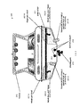
- FIG. 1 illustrates, generally at 100 , one embodiment of the invention showing a side view with major component blocks and functions.
- boat At 101 is a transom deployable water pick up, shown here in the down position.
- 104 is a rear water pick up hose.
- At 102 is a rear ballast tank.
- At 103 is a front water pick up hose.
- At 105 is a water pick up (also spelled pick-up).
- At 106 is a bow ballast tank.
- At 107 is a front air vent.
- At 108 is rear air vent.
- 109 is a floor board of the boat 190 .
- At 110 is a floor board access compartment.
- the water pick up e.g. 105 as shown in FIG. 1 may be located anywhere along the hull of the boat 190 . That is it may be located at any position from the bow to the stern and from the port side to the starboard side of the boat 190 . The only requirement is that the water pick up be located below a waterline when the boat is moving through the water. In this way water is forced into the water pick up by the motion of the boat.
- the transom deployable water pick up for example 101 as shown in FIG. 1 , is movable and when positioned below the bottom of the boat the motion of the boat will force water into the water pick up. When the deployable water pick up is at or above the bottom of the boat, water will not be forced into the water pick up by the motion of the boat.
- the rate of flow of water into/out of the ballast tank, for example, 102 as shown in FIG. 1 may be controlled by the position of the transom deployable water pick up.
- the rate of flow of water into/out of the ballast tank, for example, 102 as shown in FIG. 1 may be controlled by the position of the transom deployable water pick up.
- ballast tank 106 To control the rate and/or amount of water entering a ballast tank, for example, bow ballast tank 106 , one can throttle the air vent, for example 107 front air vent. Not shown would be a valve in line with the front air vent. A fully closed valve would not let additional water in as the compressed air pressure in the ballast tank equals that from the water pick up. This same approach may be used independently or jointly to control the rate and/or amount of water entering a rear ballast tank, for example, rear ballast tank 102 .
- a front and rear air vent such as shown in FIG. 1 at 107 and 108 may be controlled together to achieve a preferred angle of inclination of the boat while accelerating and in motion. For example, by controlling the rate of fill and the amount of filling of the ballast tanks one can, for example, keep the boat level in the water.
- the bow may tend to rise which can be countered by filling the ballast tank with some water.
- the rear ballast tank and front ballast tanks can be filled with some water to maintain a level.
- FIG. 2 illustrates, generally at 200 , one embodiment of the invention showing a rear view with major component blocks and functions.
- boat At 201 -A is a transom deployable water pick up, shown here in the up position.
- At 201 -B is a transom deployable water pick up, shown here in the down position.
- At 202 -A is shown a rear ballast tank located on the port side.
- At 202 -B is shown a rear ballast tank located on the starboard side.
- At 207 -A is shown a rear air vent located on the port side for rear ballast tank 202 -A.
- At 207 -B is shown a rear air vent located on the starboard side for rear ballast tank 202 -B.
- At 211 is a swim step located on the rear of the boat.
- At 212 is a tower.
- At 213 is a propeller.
- At 214 is a motor exhaust.
- ballast tank located on the same side as the ballast tank it is connected to, the invention is not so limited.
- a rear ballast tank located, for example on the port side may vent on the starboard side, the stern of the boat, etc.
- FIG. 3 illustrates, generally at 300 , one embodiment of the invention showing a top view with major component blocks and functions.
- boat At 301 -A is a transom deployable water pick up on the port side of the boat 390 .
- At 301 -B is a transom deployable water pick up on the starboard side.
- At 302 -A is shown a rear ballast tank located on the port side.
- At 302 -B is shown a rear ballast tank located on the starboard side.
- At 304 -A is a rear water pick up hose on the port side.
- 304 -B is a rear water pick up hose on the starboard side.
- At 308 -A is shown a rear air vent located on the port side for rear ballast tank 302 -A.
- At 308 -B is shown a rear air vent located on the starboard side for rear ballast tank 302 -B.
- At 305 is a front water pick up.
- At 303 is a front water pick up hose.
- At 307 is a front air vent.
- At 306 is a bow ballast tank.
- FIG. 3 illustrates one bow ballast tank and two rear ballast tanks with their associated pick ups and air vents
- the invention is not so limited.
- FIG. 3 illustrates for example the water pick up 305 being substantially located on a centerline from the bow to the stern
- the invention is not so limited and the water pick up, for example, water pick up 305 may be mounted anywhere on the hull of boat 390 .
- FIG. 3 illustrates for example the transom deployable water pick ups being on the transom
- deployable water pick ups may be deployed anywhere from the boat. So for example, but not limited to water pick up 305 may be located in the stern of the boat 390 with the front water pick up hose running from the stern to the bow ballast tank.
- deployable water pick ups similar to the transom deployable pickups may be located anywhere, for example, but not limited to the bow of boat 390 and would have the water pick up hose running to the rear ballast tank(s).
- FIG. 4 illustrates, generally at 400 , one embodiment of the invention showing a side view with major component blocks and functions.
- boat At 402 is a floor board.
- 404 is a floor board access lid to a first water tight compartment.
- 406 is an air vent.
- 408 is a floor board access lid to a second water tight compartment.
- 410 is a drain/intake valve.
- 412 is a water drain hose.
- At 414 is a ballast tank.
- At 416 is a scupper water pick up.
- At 418 is an intake valve.
- the intake valve 418 may be used to throttle water entering and exiting the ballast tank 414 .
- Intake valve 418 can control the water flow. If the ballast tank 414 has water above a water line, then there will be a force exerted for water to flow from the ballast tank 414 through the scupper water pick up 416 . If this force is greater than the force for water to enter the scupper water pick up 416 , then water will exit. Intake valve 418 can control this water flow as well. If the intake valve 418 is closed then water can neither enter nor exit.
- the intake valve 418 may be controlled manually, electrically, pneumatically, hydraulically, or by any other means that provides mechanical movement.
- the scupper water pick up 416 extends beyond the bottom of the hull and is mounted at an angle.
- the distance beyond the hull bottom and the angle with respect to the hull, as well as, for example, the diameter of the scupper water pick up may be varied to provide the fill rate desired at a given speed of the boat 490 .
- the angle of the scupper water pick up may be 10 degrees.
- Drain/intake valve 410 similarly can control draining of water and intake of water. When ballast tank 414 has water in it and the boat is accelerating forward there will be exerted a force as the water attempts to exit through the drain/intake valve 410 and out the water drain hose 412 .
- Intake valve 418 may be used in conjunction with a valve (not shown in FIG. 4 ) inline with air vent 406 to control entry/exit of water into/out of ballast tank 414 .
- FIG. 5 illustrates, generally at 500 , one embodiment of the invention showing a side view with major component blocks and functions.
- boat At 504 is a floor board access lid to a first water tight compartment.
- At 518 is an intake valve.
- At 502 is a floor board.
- At 506 is an air vent.
- At 514 is a ballast tank.
- At 532 is flush mounted water pick up duct. As may be seen the flush mounted water pick up duct 532 has a elongated front scoop toward the bow and a more abrupt scoop toward the stern.
- the flush mounted water pick up duct 532 has the advantage of not protruding beyond the outer surface of the hull. This provides a smoother surface than a protrusion.
- the intake valve 618 may be used to throttle water entering and exiting the ballast tank 614 .
- Intake valve 618 can control the water flow. If the ballast tank 614 has water above a water line, then there will be a force exerted for water to flow from the ballast tank 614 through the scupper water pick up 616 . If this force is greater than the force for water to enter the scupper water pick up 616 , then water will exit. Intake valve 618 can control this water flow as well. If the intake valve 618 is closed then water can neither enter nor exit.
- the intake valve 618 may be controlled manually, electrically, pneumatically, hydraulically, or by any other means that provides mechanical movement. In this embodiment as illustrate in FIG. 6 the scupper water pick up 616 extends partially beyond the surface of the hull.
- FIG. 7 illustrates, generally at 700 , one embodiment of the invention showing a side view with major component blocks and functions. Generally at 790 is boat.
- At 708 is a floor board access lid to a water tight compartment.
- a drain/intake valve At 710 is a drain/intake valve.
- a water drain hose At 712 is a water drain hose.
- a ballast tank At 713 is a transom mounted scupper water pick up and supply tube.
- Drain/intake valve 710 can control draining of water and intake of water. When ballast tank 714 has water in it and the boat 790 is accelerating forward there will be exerted a force as the water attempts to exit through the drain/intake valve 710 and out the water drain hose 712 .
- FIG. 8 illustrates, generally at 800 , one embodiment of the invention showing a side view with major component blocks and functions.
- boat Generally at 890 is boat.
- a floor board access lid to a water tight compartment.
- a drain/intake valve At 810 is a drain/intake valve.
- At 812 is a water drain hose.
- At 814 is a ballast tank.
- At 824 is an exploded view of one embodiment of a drain/intake valve 810 which is an electrically activated gate valve.
- Drain/intake valve 810 can control draining of water and intake of water. When ballast tank 814 has water in it and the boat 890 is accelerating forward there will be exerted a force as the water attempts to exit through the drain/intake valve 810 and out the water drain hose 812 .
- FIG. 9 illustrates, generally at 900 , one embodiment of the invention showing a flow chart.
- a bow water pick-up on a hull of a boat mounts a port deployable water pick up on a transom of said boat.
- a starboard deployable water pick up on a starboard of said boat mounts at 908 when said boat is in motion fill a bow ballast tank from said bow water pickup, and fill a rear port ballast tank from said port deployable water pick up, and fill a rear starboard ballast tank from said starboard deployable water pick up.
- 910 , 912 , 914 , and 916 are each individually optional.
- At 910 mount said bow water pick-up flush with said hull of said boat and mounting said bow water pick-up between said bow ballast tank and a most forward of said rear port ballast tank and said rear starboard ballast tank.
- At 912 install a valve between said bow water pick-up and said bow ballast tank.
- At 914 connect a port water drain hose between said rear port ballast tank and an opening on a port side of said hull; and connect a starboard water drain hose between said rear starboard ballast tank and an opening on a starboard side of said hull.
- At 916 install a valve inline with said port water drain hose; install a valve inline with said port starboard drain hose; and control said valve inline with said port water drain hose and said valve inline with said port starboard drain hose and said port deployable water pick up and said starboard deployable water pick up and said valve between said bow water pick-up and said bow ballast tank such that when said boat is accelerating through water it is substantially level.
- FIG. 10 illustrates, generally at 1000 , various embodiments of the invention showing the following.
- a wake enlargement system for improving a wake generated by a boat comprising: the boat having a hull having a bow and a stern; a water pick-up having an input and an output, the water pick-up input flush mounted on a bottom surface of the hull; and one or more ballast tanks having a water input and an air output, the ballast water input in operative communication with the water pick-up output.
- the water pick-up extends beyond an outer surface of the bottom surface of the hull. 3.
- the system of claim 1 wherein the water pick-up is flush mounted with an outer surface of the bottom surface of the hull, the bottom surface of the hull not a transom, and the water pick-up in operative communication with a hole through the bottom surface of the hull not the transom.
- the one or more ballast tanks is one bow ballast tank centered about a centerline running from the stern to the bow of the hull, and the water pick-up is located aft of the bow ballast tank. 5.
- the water pick-up is centered about the centerline running from the stern to the bow of the hull. 6.
- ballast water input in operative communication with the water pick-up output is a direct connection without any intervening valves.
- the water pick-up extends beyond an outer surface of the bottom surface of the hull, and wherein the one or more ballast tanks is one bow ballast tank centered about a centerline running from the stern to the bow of the hull, and wherein the water pick-up is located aft of the bow ballast tank.
- a wake enlargement system for improving a wake generated by a boat comprising: the boat having a hull, a bow, and a stern; a water pick-up having an input and an output, the water pick-up input mounted on a bottom of the hull, and situated between the bow and an amidships: one or more ballast tanks having a water input and an air output, the ballast water input in operative communication with the water pick-up output.
- the water pick up mounted on the bottom of the hull extends beyond the bottom of the hull.
- an intake value is disposed between the pick-up output and the ballast water input.
- a method comprising: mounting a ballast tank in a boat; mounting a water pick up on a bottom of a hull of the boat, the water pickup not on a transom, wherein no portion of the water pick up extends beyond the bottom of the hull of the boat; mounting a valve in the boat; connecting an input to the valve to the water pick up; and
- the method of claim 12 further comprising mounting the ballast tank forward of the water pick up. 14. The method of claim 12 further comprising mounting the ballast tank aft of the water pick up. 15. The method of claim 13 further comprising mounting the ballast tank so that a portion of the ballast tank is above a waterline when the ballast tank is empty and the boat is at rest in water. 16. The method of claim 14 further comprising mounting the ballast tank so that a portion of the ballast tank is above a waterline when the ballast tank is empty and the boat is at rest in water. 17. The method of claim 16 further comprising actuating the valve to control a rate of water pick up from the water pickup. 18.
- ballast tank has an air vent with an air vent valve in line. 19.
- the method of claim 18 further comprising actuating the air vent valve to control a rate of water pick up from the water pickup. 20.
- the method of claim 18 further comprising actuating the valve and the air vent valve to control a rate of water pick up from the water pickup.
- one embodiment or “an embodiment” or similar phrases means that the feature(s) being described are included in at least one embodiment of the invention. References to “one embodiment” in this description do not necessarily refer to the same embodiment; however, neither are such embodiments mutually exclusive. Nor does “one embodiment” imply that there is but a single embodiment of the invention. For example, a feature, structure, act, etc. described in “one embodiment” may also be included in other embodiments. Thus, the invention may include a variety of combinations and/or integrations of the embodiments described herein.
Landscapes
- Chemical & Material Sciences (AREA)
- Engineering & Computer Science (AREA)
- Combustion & Propulsion (AREA)
- Mechanical Engineering (AREA)
- Ocean & Marine Engineering (AREA)
- Physics & Mathematics (AREA)
- Fluid Mechanics (AREA)
- Other Liquid Machine Or Engine Such As Wave Power Use (AREA)
Abstract
A Method and Apparatus for Wake Enlargement System have been disclosed. By using water pick ups that are mounted on a boat controlled filling of ballast tanks is possible without the use of pumps.
Description
The present Application for Patent is related to, and claims priority to, U.S. Patent Application No. 61/460,064 titled “Wake Enlargement System (Pure Vert #3)” filed Dec. 27, 2010, and is hereby incorporated herein by reference. The present Application for Patent is related to, and claims priority to, U.S. patent application Ser. No. 13/337,118 titled “Method and Apparatus for Wake Enlargement System” filed Dec. 24, 2011, now U.S. Pat. No. 8,739,723 issued Jun. 3, 2014, and is hereby incorporated herein by reference. The present Application for Patent is related to, and claims priority to, U.S. patent application Ser. No. 14/187,256 titled “Method and Apparatus for Wake Enlargement System” filed Feb. 22, 2014, now U.S. Pat. No. 9,045,204 issued Jun. 2, 2015, and is hereby incorporated herein by reference. The present Application for Patent is related to, and claims priority to, U.S. patent application Ser. No. 14/701,512 titled “Method and Apparatus for Wake Enlargement System” filed Apr. 30, 2015, now U.S. Pat. No. 9,272,762 issued Mar. 1, 2016, and is hereby incorporated herein by reference. The present Application for Patent is related to, and claims priority to, U.S. patent application Ser. No. 15/003,736 titled “Method and Apparatus for Wake Enlargement System” filed Jan. 21, 2016, and is hereby incorporated herein by reference.
The present invention pertains to water sports. More particularly, the present invention relates to a Method and Apparatus for Wake Enlargement System.
In several water sports, for example, but not limited to, wakeboarding, waterskiing, etc., “getting air” is desirable. One way of “getting air” is to launch oneself off a wave into the air. This wave can be created by a boat, for example, towing person(s) engaging in the water sport. This wave created by the boat is often referred to as a wake. To create a wake a boat must displace water as it moves forward. One approach to displace as much water as possible is to lower a boat in the water. This lowering can be achieved by placing ballast(s) in the boat. However having a boat lower in the water, that is displacing more water, requires more energy to get up to speed since more water needs to be displaced which requires more energy. This presents a problem.
One approach is to use water as a ballast. In the past, such systems have been filled by either water pumps or flooding through the bottom of the boat. However, water pumps are complicated, need a source of power, are heavy, etc., and so this presents a problem. Using a flooding system will only fill ballast tanks to the waterline, and so this presents a problem.
The invention is illustrated by way of example and not limitation in the figures of the accompanying drawings in which:
In one embodiment of the invention, the system does not use pumps to fill ballast tank(s). In one embodiment of the invention, the system does not use flooding to fill ballast tank(s). In one embodiment of the invention, the system does not use gates or valves.
In one embodiment of the invention, the system does not use pumps to fill some ballast tank(s). In one embodiment of the invention, the system does not use gates or valves for controlling filling/emptying of some of the ballast tank(s).
In one embodiment of the invention, the system uses a combination of no valves, and valves to control filling/emptying of some of the ballast tank(s).
In one embodiment of the invention, the system works on water pressure to fill ballast tank(s). In one embodiment of the invention, the system works on water pressure developed while the boat is in forward motion to fill ballast tank(s). In one embodiment of the invention, water pressure developed by the boat in forward motion is used to force feed ballast tank(s) and uses an air venting system.
In one embodiment of the invention, the system uses gravity to empty ballast tank(s). In one embodiment of the invention, the system uses the boat's forward motion to empty ballast tank(s). In one embodiment of the invention, the system uses gravity and the boat's forward motion to empty ballast tank(s).
In one embodiment of the invention, the system uses water pick-ups that are mounted through the bottom of the boat. In one embodiment of the invention, the system uses deployable water pick-ups that are mounted on the boat. In one embodiment of the invention, the system uses deployable water pick-ups that are mounted on the boat and which may be raised to eliminate drag on the boat as it is moving.
In one embodiment of the invention, the system uses deployable water pick-ups that are mounted on the boat transom. In one embodiment of the invention, the system uses deployable water pick-ups that are deployed on the boat transom. In one embodiment of the invention, the system uses deployable water pick-ups that are deployed past the boat transom.
In one embodiment of the invention, using the force feed water pick-up allows the ballast tank(s) to be taller than the waterline and thus being able to fill ballast tank(s) above the waterline thereby adding more water which increases the weight on the boat which results in a bigger wake.
In one embodiment of the invention, using the force feed water pick-up creates pressure without the use of pumps, diversion valves, check valves, etc.
The water pick up, e.g. 105 as shown in FIG. 1 may be located anywhere along the hull of the boat 190. That is it may be located at any position from the bow to the stern and from the port side to the starboard side of the boat 190. The only requirement is that the water pick up be located below a waterline when the boat is moving through the water. In this way water is forced into the water pick up by the motion of the boat.
The transom deployable water pick up, for example 101 as shown in FIG. 1 , is movable and when positioned below the bottom of the boat the motion of the boat will force water into the water pick up. When the deployable water pick up is at or above the bottom of the boat, water will not be forced into the water pick up by the motion of the boat.
Since the transom deployable water pick up, e.g. 101 as shown in FIG. 1 is movable, the rate of flow of water into/out of the ballast tank, for example, 102 as shown in FIG. 1 may be controlled by the position of the transom deployable water pick up. When fully below the bottom of the boat there is maximum pick up due to motion of the boat and when raised for example, out of the water, there will be no force from the water the boat is in.
To control the rate and/or amount of water entering a ballast tank, for example, bow ballast tank 106, one can throttle the air vent, for example 107 front air vent. Not shown would be a valve in line with the front air vent. A fully closed valve would not let additional water in as the compressed air pressure in the ballast tank equals that from the water pick up. This same approach may be used independently or jointly to control the rate and/or amount of water entering a rear ballast tank, for example, rear ballast tank 102.
In one embodiment a front and rear air vent, such as shown in FIG. 1 at 107 and 108 may be controlled together to achieve a preferred angle of inclination of the boat while accelerating and in motion. For example, by controlling the rate of fill and the amount of filling of the ballast tanks one can, for example, keep the boat level in the water.
For example during initial acceleration, the bow may tend to rise which can be countered by filling the ballast tank with some water. As the boat begins to plane, the rear ballast tank and front ballast tanks can be filled with some water to maintain a level.
In one embodiment, for example, as illustrated in FIG. 1 there are no intervening valves located between water pick up 105 and the input to the bow ballast tank 106.
Note that while an air vent is shown located on the same side as the ballast tank it is connected to, the invention is not so limited. For example, a rear ballast tank located, for example on the port side may vent on the starboard side, the stern of the boat, etc.
While FIG. 3 illustrates one bow ballast tank and two rear ballast tanks with their associated pick ups and air vents, the invention is not so limited. For example, there may be one or more bow ballast tanks having one or more pick ups and one or more air vents. Likewise there may be one or more rear ballast tanks having one or more pick ups and one or more air vents.
While FIG. 3 illustrates for example the water pick up 305 being substantially located on a centerline from the bow to the stern, the invention is not so limited and the water pick up, for example, water pick up 305 may be mounted anywhere on the hull of boat 390. Likewise, while FIG. 3 illustrates for example the transom deployable water pick ups being on the transom, deployable water pick ups may be deployed anywhere from the boat. So for example, but not limited to water pick up 305 may be located in the stern of the boat 390 with the front water pick up hose running from the stern to the bow ballast tank. Likewise deployable water pick ups similar to the transom deployable pickups may be located anywhere, for example, but not limited to the bow of boat 390 and would have the water pick up hose running to the rear ballast tank(s).
In one embodiment, for example, as illustrated in FIG. 4 , the intake valve 418 may be used to throttle water entering and exiting the ballast tank 414. For example, if the boat 490 is in forward motion water from the scupper water pick up will have a force to try and enter ballast tank 414. Intake valve 418 can control the water flow. If the ballast tank 414 has water above a water line, then there will be a force exerted for water to flow from the ballast tank 414 through the scupper water pick up 416. If this force is greater than the force for water to enter the scupper water pick up 416, then water will exit. Intake valve 418 can control this water flow as well. If the intake valve 418 is closed then water can neither enter nor exit.
The intake valve 418 may be controlled manually, electrically, pneumatically, hydraulically, or by any other means that provides mechanical movement.
In one embodiment, for example, as illustrated in FIG. 4 , the scupper water pick up 416 extends beyond the bottom of the hull and is mounted at an angle. The distance beyond the hull bottom and the angle with respect to the hull, as well as, for example, the diameter of the scupper water pick up may be varied to provide the fill rate desired at a given speed of the boat 490. In one embodiment for example the angle of the scupper water pick up may be 10 degrees.
Drain/intake valve 410 similarly can control draining of water and intake of water. When ballast tank 414 has water in it and the boat is accelerating forward there will be exerted a force as the water attempts to exit through the drain/intake valve 410 and out the water drain hose 412.
The flush mounted water pick up duct 532 has the advantage of not protruding beyond the outer surface of the hull. This provides a smoother surface than a protrusion.
In one embodiment, for example, as illustrated in FIG. 6 , the intake valve 618 may be used to throttle water entering and exiting the ballast tank 614. For example, if the boat 690 is in forward motion water from the scupper water pick up will have a force to try and enter ballast tank 614. Intake valve 618 can control the water flow. If the ballast tank 614 has water above a water line, then there will be a force exerted for water to flow from the ballast tank 614 through the scupper water pick up 616. If this force is greater than the force for water to enter the scupper water pick up 616, then water will exit. Intake valve 618 can control this water flow as well. If the intake valve 618 is closed then water can neither enter nor exit.
The intake valve 618 may be controlled manually, electrically, pneumatically, hydraulically, or by any other means that provides mechanical movement. In this embodiment as illustrate in FIG. 6 the scupper water pick up 616 extends partially beyond the surface of the hull.
At 708 is a floor board access lid to a water tight compartment. At 710 is a drain/intake valve. At 712 is a water drain hose. At 714 is a ballast tank. At 713 is a transom mounted scupper water pick up and supply tube.
Drain/intake valve 710 can control draining of water and intake of water. When ballast tank 714 has water in it and the boat 790 is accelerating forward there will be exerted a force as the water attempts to exit through the drain/intake valve 710 and out the water drain hose 712.
Drain/intake valve 810 can control draining of water and intake of water. When ballast tank 814 has water in it and the boat 890 is accelerating forward there will be exerted a force as the water attempts to exit through the drain/intake valve 810 and out the water drain hose 812.
connecting an output from the valve to the ballast tank. 13. The method of claim 12 further comprising mounting the ballast tank forward of the water pick up. 14. The method of claim 12 further comprising mounting the ballast tank aft of the water pick up. 15. The method of claim 13 further comprising mounting the ballast tank so that a portion of the ballast tank is above a waterline when the ballast tank is empty and the boat is at rest in water. 16. The method of claim 14 further comprising mounting the ballast tank so that a portion of the ballast tank is above a waterline when the ballast tank is empty and the boat is at rest in water. 17. The method of claim 16 further comprising actuating the valve to control a rate of water pick up from the water pickup. 18. The method of claim 16 wherein the ballast tank has an air vent with an air vent valve in line. 19. The method of claim 18 further comprising actuating the air vent valve to control a rate of water pick up from the water pickup. 20. The method of claim 18 further comprising actuating the valve and the air vent valve to control a rate of water pick up from the water pickup.
Thus a Method and Apparatus for Wake Enlargement System have been described.
For purposes of discussing and understanding the invention, it is to be understood that various terms are used by those knowledgeable in the art to describe techniques and approaches. Furthermore, in the description, for purposes of explanation, numerous specific details are set forth in order to provide a thorough understanding of the present invention. It will be evident, however, to one of ordinary skill in the art that the present invention may be practiced without these specific details. In some instances, well-known structures and devices are shown in block diagram form, rather than in detail, in order to avoid obscuring the present invention. These embodiments are described in sufficient detail to enable those of ordinary skill in the art to practice the invention, and it is to be understood that other embodiments may be utilized and that logical, mechanical, electrical, and other changes may be made without departing from the scope of the present invention.
As used in this description, “one embodiment” or “an embodiment” or similar phrases means that the feature(s) being described are included in at least one embodiment of the invention. References to “one embodiment” in this description do not necessarily refer to the same embodiment; however, neither are such embodiments mutually exclusive. Nor does “one embodiment” imply that there is but a single embodiment of the invention. For example, a feature, structure, act, etc. described in “one embodiment” may also be included in other embodiments. Thus, the invention may include a variety of combinations and/or integrations of the embodiments described herein.
As used in this description, “substantially” or “substantially equal” or similar phrases are used to indicate that the items are very close or similar. Since two physical entities can never be exactly equal, a phrase such as ““substantially equal” is used to indicate that they are for all practical purposes equal.
As used in this description “pick up” or “pickup” or “pick-up” or similar language refers to the same thing.
It is to be understood that in any one or more embodiments of the invention where alternative approaches or techniques are discussed that any and all such combinations as might be possible are hereby disclosed. For example, if there are five techniques discussed that are all possible, then denoting each technique as follows: A, B, C, D, E, each technique may be either present or not present with every other technique, thus yielding 2^5 or 32 combinations, in binary order ranging from not A and not B and not C and not D and not E to A and B and C and D and E. Applicant(s) hereby claims all such possible combinations. Applicant(s) hereby submit that the foregoing combinations comply with applicable EP (European Patent) standards. No preference is given any combination.
Thus a Method and Apparatus for Wake Enlargement System have been described.
Claims (11)
1. A wake enlargement system for improving a wake generated by a boat, the system comprising:
the boat having a hull, the hull having a bow, a stern, a bottom surface, and a transom;
a water pick-up having an input and an output, the water pick-up mounted on the bottom surface of the hull;
one or more ballast tanks having a water input, an air output, and a water output;
wherein the one or more ballast tanks ballast water input is in operative communication with the water pick-up output;
wherein the one or more ballast tanks air output is in operative communication with one or more air vents; and
wherein the one or more ballast tanks water output is in operative communication with one or more openings in the transom.
2. The system of claim 1 wherein the water pick-up extends beyond an outer surface of the bottom surface of the hull.
3. The system of claim 1 wherein the water pick-up is flush mounted with an outer surface of the bottom surface of the hull, the bottom surface of the hull not a transom, and the water pick-up in operative communication with a hole through the bottom surface of the hull not the transom.
4. The system of claim 1 wherein the one or more air vents are through openings in the hull.
5. The system of claim 4 wherein the water pick-up is centered about the centerline running from the stern to the bow of the hull.
6. The system of claim 1 wherein the one or more ballast tanks water input in operative communication with the water pick-up output is a direct connection without any intervening valves.
7. The system of claim 1 wherein the one or more ballast tanks water input in operative communication with the water pick-up output has one or more intervening valves.
8. The system of claim 1 wherein the one or more ballast tanks water output in operative communication with the one or more openings in the transom has one or more intervening valves.
9. The system of claim 1 wherein the water pick up mounted on the bottom surface of the hull extends beyond the bottom of the hull.
10. The system of claim 1 wherein one or more intake values are disposed between the water pick-up output and the one or more ballast tanks water input.
11. The system of claim 10 wherein the one or more intake values are located between a floor board and the bottom surface of the hull.
Priority Applications (4)
| Application Number | Priority Date | Filing Date | Title |
|---|---|---|---|
| US15/618,077 US10246169B1 (en) | 2010-12-27 | 2017-06-08 | Method and apparatus for wake enlargement system |
| US16/278,141 US10569846B1 (en) | 2010-12-27 | 2019-02-17 | Method and apparatus for wake enlargement system |
| US16/750,911 US11312455B1 (en) | 2010-12-27 | 2020-01-23 | Method and apparatus for wake enlargement system |
| US17/705,032 US11628912B1 (en) | 2010-12-27 | 2022-03-25 | Method and apparatus for wake enlargement system |
Applications Claiming Priority (6)
| Application Number | Priority Date | Filing Date | Title |
|---|---|---|---|
| US201061460664P | 2010-12-27 | 2010-12-27 | |
| US13/337,118 US8739723B1 (en) | 2010-12-27 | 2011-12-24 | Method and apparatus for wake enlargement system |
| US14/187,256 US9045204B1 (en) | 2010-12-27 | 2014-02-22 | Method and apparatus for wake enlargement system |
| US14/701,512 US9272762B1 (en) | 2010-12-27 | 2015-04-30 | Method and apparatus for wake enlargement system |
| US15/003,736 US9701373B1 (en) | 2010-12-27 | 2016-01-21 | Method and apparatus for wake enlargement system |
| US15/618,077 US10246169B1 (en) | 2010-12-27 | 2017-06-08 | Method and apparatus for wake enlargement system |
Related Parent Applications (1)
| Application Number | Title | Priority Date | Filing Date |
|---|---|---|---|
| US15/003,736 Continuation US9701373B1 (en) | 2010-12-27 | 2016-01-21 | Method and apparatus for wake enlargement system |
Related Child Applications (1)
| Application Number | Title | Priority Date | Filing Date |
|---|---|---|---|
| US16/278,141 Continuation US10569846B1 (en) | 2010-12-27 | 2019-02-17 | Method and apparatus for wake enlargement system |
Publications (1)
| Publication Number | Publication Date |
|---|---|
| US10246169B1 true US10246169B1 (en) | 2019-04-02 |
Family
ID=50781107
Family Applications (8)
| Application Number | Title | Priority Date | Filing Date |
|---|---|---|---|
| US13/337,118 Active 2032-08-08 US8739723B1 (en) | 2010-12-27 | 2011-12-24 | Method and apparatus for wake enlargement system |
| US14/187,256 Active US9045204B1 (en) | 2010-12-27 | 2014-02-22 | Method and apparatus for wake enlargement system |
| US14/701,512 Active US9272762B1 (en) | 2010-12-27 | 2015-04-30 | Method and apparatus for wake enlargement system |
| US15/003,736 Active US9701373B1 (en) | 2010-12-27 | 2016-01-21 | Method and apparatus for wake enlargement system |
| US15/618,077 Active US10246169B1 (en) | 2010-12-27 | 2017-06-08 | Method and apparatus for wake enlargement system |
| US16/278,141 Active US10569846B1 (en) | 2010-12-27 | 2019-02-17 | Method and apparatus for wake enlargement system |
| US16/750,911 Active 2032-04-10 US11312455B1 (en) | 2010-12-27 | 2020-01-23 | Method and apparatus for wake enlargement system |
| US17/705,032 Active US11628912B1 (en) | 2010-12-27 | 2022-03-25 | Method and apparatus for wake enlargement system |
Family Applications Before (4)
| Application Number | Title | Priority Date | Filing Date |
|---|---|---|---|
| US13/337,118 Active 2032-08-08 US8739723B1 (en) | 2010-12-27 | 2011-12-24 | Method and apparatus for wake enlargement system |
| US14/187,256 Active US9045204B1 (en) | 2010-12-27 | 2014-02-22 | Method and apparatus for wake enlargement system |
| US14/701,512 Active US9272762B1 (en) | 2010-12-27 | 2015-04-30 | Method and apparatus for wake enlargement system |
| US15/003,736 Active US9701373B1 (en) | 2010-12-27 | 2016-01-21 | Method and apparatus for wake enlargement system |
Family Applications After (3)
| Application Number | Title | Priority Date | Filing Date |
|---|---|---|---|
| US16/278,141 Active US10569846B1 (en) | 2010-12-27 | 2019-02-17 | Method and apparatus for wake enlargement system |
| US16/750,911 Active 2032-04-10 US11312455B1 (en) | 2010-12-27 | 2020-01-23 | Method and apparatus for wake enlargement system |
| US17/705,032 Active US11628912B1 (en) | 2010-12-27 | 2022-03-25 | Method and apparatus for wake enlargement system |
Country Status (1)
| Country | Link |
|---|---|
| US (8) | US8739723B1 (en) |
Cited By (3)
| Publication number | Priority date | Publication date | Assignee | Title |
|---|---|---|---|---|
| US10569846B1 (en) * | 2010-12-27 | 2020-02-25 | Michael Murphy | Method and apparatus for wake enlargement system |
| US12097930B2 (en) | 2011-09-16 | 2024-09-24 | Malibu Boats, Llc | Surf wake system for a watercraft |
| US12139236B1 (en) | 2019-04-05 | 2024-11-12 | Malibu Boats, Llc | Water sports boat with foil displacement system |
Families Citing this family (29)
| Publication number | Priority date | Publication date | Assignee | Title |
|---|---|---|---|---|
| US8578873B2 (en) | 2011-09-16 | 2013-11-12 | Malibu Boats, Llc | Surf wake system for a watercraft |
| US8857356B1 (en) * | 2011-12-02 | 2014-10-14 | Michael Murphy | Method and apparatus for insta fill wake system |
| KR101347957B1 (en) * | 2012-04-25 | 2014-01-15 | 조동진 | Boat having buoyancy unit |
| US9689395B2 (en) * | 2012-07-06 | 2017-06-27 | Skier's Choice, Inc. | Wakeboat with dynamic wave control |
| US8798825B1 (en) | 2012-07-06 | 2014-08-05 | Richard L. Hartman | Wakeboat hull control systems and methods |
| US9254896B2 (en) * | 2013-08-20 | 2016-02-09 | Medallion Instrumentation Systems, Llc | Ballast system and related methods |
| US8833286B1 (en) | 2013-10-11 | 2014-09-16 | Mastercraft Boat Company, Llc | Wake-modifying device for a boat |
| US10358189B2 (en) | 2013-10-11 | 2019-07-23 | Mastercraft Boat Company, Llc | Wake-modifying device for a boat |
| US9802684B2 (en) | 2013-10-11 | 2017-10-31 | Mastercraft Boat Company, Llc | Wake-modifying device for a boat |
| US9669903B2 (en) | 2014-02-04 | 2017-06-06 | Malibu Boats, Llc | Methods and apparatus for facilitating watercraft planing |
| NZ731433A (en) * | 2014-11-19 | 2018-08-31 | Masayuki Izume | Planing ship and method for manufacturing same |
| US9891620B2 (en) | 2015-07-15 | 2018-02-13 | Malibu Boats, Llc | Control systems for water-sports watercraft |
| US11505289B2 (en) | 2016-09-09 | 2022-11-22 | Richard L. Hartman | Wakeboat bilge measurement assemblies and methods |
| US10329004B2 (en) | 2016-09-09 | 2019-06-25 | Richard L. Hartman | Wakeboat ballast measurement assemblies and methods |
| US11014634B2 (en) | 2016-09-09 | 2021-05-25 | Richard L. Hartman | Hydraulic power sources for watercraft and methods for providing hydraulic power aboard a watercraft |
| US10829186B2 (en) | 2016-09-09 | 2020-11-10 | Richard L. Hartman | Wakeboat ballast measurement assemblies and methods |
| US11014635B2 (en) | 2016-09-09 | 2021-05-25 | Richard L. Hartman | Power source assemblies and methods for distributing power aboard a watercraft |
| US10611440B2 (en) | 2016-09-09 | 2020-04-07 | Richard L. Hartman | Boat propulsion assemblies and methods |
| US10611439B2 (en) | 2016-09-09 | 2020-04-07 | Richard L. Hartman | Wakeboat engine hydraulic pump mounting apparatus and methods |
| US10864971B2 (en) | 2016-09-09 | 2020-12-15 | Richard L. Hartman | Wakeboat hydraulic manifold assemblies and methods |
| US10435122B2 (en) | 2016-09-09 | 2019-10-08 | Richard L. Hartman | Wakeboat propulsion apparatuses and methods |
| AU2017225097B2 (en) | 2016-09-09 | 2020-07-23 | Richard L. Hartman | Wakeboat Engine Powered Ballasting Apparatus and Methods |
| US11254395B2 (en) | 2016-09-09 | 2022-02-22 | Richard L. Hartman | Aquatic invasive species control apparatuses and methods for watercraft |
| AU2018325525B2 (en) * | 2017-09-01 | 2022-07-21 | Mastercraft Boat Company, Llc | Ballast system for a boat and method of operating a boat |
| US10745084B2 (en) | 2018-01-10 | 2020-08-18 | Avalon & Tahoe Mfg. Inc. | System and method for enhancing a wake profile for pontoon boats |
| US11110996B2 (en) * | 2020-02-07 | 2021-09-07 | Tulip Factory, LLC | Recreational watercraft with ballast system |
| US11932356B1 (en) | 2020-08-24 | 2024-03-19 | Malibu Boats, Llc | Powered swim platform |
| US12252222B2 (en) | 2020-09-23 | 2025-03-18 | Mastercraft Boat Company, Llc | Boats, methods, and devices used to generate a desired wake |
| US11352117B1 (en) | 2021-02-08 | 2022-06-07 | Gigawave Llc | Enhanced wave generation methods and systems |
Citations (13)
| Publication number | Priority date | Publication date | Assignee | Title |
|---|---|---|---|---|
| US3085535A (en) * | 1959-08-24 | 1963-04-16 | Hunt Ind Inc | Boat hull |
| US3186371A (en) | 1964-04-01 | 1965-06-01 | Moore George Arlington | Speedboat stabilizer |
| US3747554A (en) | 1971-06-03 | 1973-07-24 | R Allen | Combination chock and fairlead fitting |
| US4341177A (en) | 1979-03-29 | 1982-07-27 | Kawasaki Jukogyo Kaikan Kaisha | Small watercraft |
| US4528927A (en) | 1983-03-22 | 1985-07-16 | Achilles Corporation | Planing type boat |
| US4548148A (en) * | 1983-01-25 | 1985-10-22 | Bloomfield Iii John W | Glass bottom boat |
| US5215025A (en) | 1990-07-10 | 1993-06-01 | K10 Corporation | Boat |
| US5645003A (en) | 1991-10-14 | 1997-07-08 | Grinde; Geir | Hull for a high speed boat |
| US6044788A (en) * | 1998-03-09 | 2000-04-04 | Correct Craft, Inc. | Water sports performance system and method |
| US6234099B1 (en) | 1999-12-07 | 2001-05-22 | Robert H. Jessen | Methods and means to control boat wake |
| US6427616B1 (en) | 2001-04-05 | 2002-08-06 | Toni Lynn Hagen | Wake enhancement assembly |
| US6953002B2 (en) * | 2002-03-26 | 2005-10-11 | Jessen Robert H | Boat wake system |
| US8739723B1 (en) * | 2010-12-27 | 2014-06-03 | Michael Murphy | Method and apparatus for wake enlargement system |
-
2011
- 2011-12-24 US US13/337,118 patent/US8739723B1/en active Active
-
2014
- 2014-02-22 US US14/187,256 patent/US9045204B1/en active Active
-
2015
- 2015-04-30 US US14/701,512 patent/US9272762B1/en active Active
-
2016
- 2016-01-21 US US15/003,736 patent/US9701373B1/en active Active
-
2017
- 2017-06-08 US US15/618,077 patent/US10246169B1/en active Active
-
2019
- 2019-02-17 US US16/278,141 patent/US10569846B1/en active Active
-
2020
- 2020-01-23 US US16/750,911 patent/US11312455B1/en active Active
-
2022
- 2022-03-25 US US17/705,032 patent/US11628912B1/en active Active
Patent Citations (16)
| Publication number | Priority date | Publication date | Assignee | Title |
|---|---|---|---|---|
| US3085535A (en) * | 1959-08-24 | 1963-04-16 | Hunt Ind Inc | Boat hull |
| US3186371A (en) | 1964-04-01 | 1965-06-01 | Moore George Arlington | Speedboat stabilizer |
| US3747554A (en) | 1971-06-03 | 1973-07-24 | R Allen | Combination chock and fairlead fitting |
| US4341177A (en) | 1979-03-29 | 1982-07-27 | Kawasaki Jukogyo Kaikan Kaisha | Small watercraft |
| US4548148A (en) * | 1983-01-25 | 1985-10-22 | Bloomfield Iii John W | Glass bottom boat |
| US4528927A (en) | 1983-03-22 | 1985-07-16 | Achilles Corporation | Planing type boat |
| US5215025A (en) | 1990-07-10 | 1993-06-01 | K10 Corporation | Boat |
| US5645003A (en) | 1991-10-14 | 1997-07-08 | Grinde; Geir | Hull for a high speed boat |
| US6044788A (en) * | 1998-03-09 | 2000-04-04 | Correct Craft, Inc. | Water sports performance system and method |
| US6234099B1 (en) | 1999-12-07 | 2001-05-22 | Robert H. Jessen | Methods and means to control boat wake |
| US6427616B1 (en) | 2001-04-05 | 2002-08-06 | Toni Lynn Hagen | Wake enhancement assembly |
| US6953002B2 (en) * | 2002-03-26 | 2005-10-11 | Jessen Robert H | Boat wake system |
| US8739723B1 (en) * | 2010-12-27 | 2014-06-03 | Michael Murphy | Method and apparatus for wake enlargement system |
| US9045204B1 (en) * | 2010-12-27 | 2015-06-02 | Michael Murphy | Method and apparatus for wake enlargement system |
| US9272762B1 (en) * | 2010-12-27 | 2016-03-01 | Michael Murphy | Method and apparatus for wake enlargement system |
| US9701373B1 (en) * | 2010-12-27 | 2017-07-11 | Michael Murphy | Method and apparatus for wake enlargement system |
Non-Patent Citations (3)
| Title |
|---|
| Performance Report Wakeboard "Fineline Wave", vol. 1, Issue 1, 1997, p. 22. |
| Performance Report Wakeboard "Ultimate Gear", vol. 1, Issue 3, 1997, p. 45. |
| Powerboat magazine article "Wake-Up call", Apr. 1997, 4 pages ending at p. 51. |
Cited By (5)
| Publication number | Priority date | Publication date | Assignee | Title |
|---|---|---|---|---|
| US10569846B1 (en) * | 2010-12-27 | 2020-02-25 | Michael Murphy | Method and apparatus for wake enlargement system |
| US11312455B1 (en) | 2010-12-27 | 2022-04-26 | Michael Murphy | Method and apparatus for wake enlargement system |
| US11628912B1 (en) | 2010-12-27 | 2023-04-18 | Michael Murphy | Method and apparatus for wake enlargement system |
| US12097930B2 (en) | 2011-09-16 | 2024-09-24 | Malibu Boats, Llc | Surf wake system for a watercraft |
| US12139236B1 (en) | 2019-04-05 | 2024-11-12 | Malibu Boats, Llc | Water sports boat with foil displacement system |
Also Published As
| Publication number | Publication date |
|---|---|
| US8739723B1 (en) | 2014-06-03 |
| US11312455B1 (en) | 2022-04-26 |
| US9272762B1 (en) | 2016-03-01 |
| US9045204B1 (en) | 2015-06-02 |
| US10569846B1 (en) | 2020-02-25 |
| US9701373B1 (en) | 2017-07-11 |
| US11628912B1 (en) | 2023-04-18 |
Similar Documents
| Publication | Publication Date | Title |
|---|---|---|
| US11628912B1 (en) | Method and apparatus for wake enlargement system | |
| US6953002B2 (en) | Boat wake system | |
| US6234099B1 (en) | Methods and means to control boat wake | |
| US11254391B2 (en) | Ballast system for a boat and method of operating a boat | |
| US7140318B1 (en) | Method and apparatus for modifying wake | |
| US9180932B2 (en) | Method and apparatus for insta fill wake system | |
| AU656247B2 (en) | Multi-hull vessel | |
| US7216601B1 (en) | Apparatus and method for a dual hull boat with control gate | |
| AU2015351153B2 (en) | Planing boat and method for manufacturing the same | |
| US20240132184A1 (en) | Wake shaping device | |
| US11964732B2 (en) | Marine surface vessel comprising an air ventilated hull | |
| CN100393577C (en) | Semi-submersible self-variable depth craft | |
| RU196940U1 (en) | HIGH PRESSURE INFLATABLE BOAT | |
| CN210942146U (en) | Ship ballast adjusting device | |
| US7540252B2 (en) | Autostabilizer device for boat hull | |
| KR101731019B1 (en) | Submersible Boat | |
| CN115416797B (en) | Stable adjustable hydrofoil with small waterplane area layout | |
| JPH10203470A (en) | Water jet propulsion high speed ship | |
| US20060137591A1 (en) | Watercraft hull with adjustable keel | |
| CN107580579B (en) | System for ship control | |
| JP2023112861A (en) | hydrofoil | |
| CN109367740A (en) | A kind of submarine hull and its method of diving under water | |
| US20190039700A1 (en) | Method and Apparatus for Planing Boat Ballast System |
Legal Events
| Date | Code | Title | Description |
|---|---|---|---|
| STCF | Information on status: patent grant |
Free format text: PATENTED CASE |
|
| FEPP | Fee payment procedure |
Free format text: MAINTENANCE FEE REMINDER MAILED (ORIGINAL EVENT CODE: REM.); ENTITY STATUS OF PATENT OWNER: SMALL ENTITY |
|
| FEPP | Fee payment procedure |
Free format text: SURCHARGE FOR LATE PAYMENT, SMALL ENTITY (ORIGINAL EVENT CODE: M2554); ENTITY STATUS OF PATENT OWNER: SMALL ENTITY |
|
| MAFP | Maintenance fee payment |
Free format text: PAYMENT OF MAINTENANCE FEE, 4TH YR, SMALL ENTITY (ORIGINAL EVENT CODE: M2551); ENTITY STATUS OF PATENT OWNER: SMALL ENTITY Year of fee payment: 4 |