US1024352A - Scale. - Google Patents
Scale. Download PDFInfo
- Publication number
- US1024352A US1024352A US60244411A US1911602444A US1024352A US 1024352 A US1024352 A US 1024352A US 60244411 A US60244411 A US 60244411A US 1911602444 A US1911602444 A US 1911602444A US 1024352 A US1024352 A US 1024352A
- Authority
- US
- United States
- Prior art keywords
- hopper
- bag
- scale beam
- scale
- closure
- Prior art date
- Legal status (The legal status is an assumption and is not a legal conclusion. Google has not performed a legal analysis and makes no representation as to the accuracy of the status listed.)
- Expired - Lifetime
Links
- 238000005303 weighing Methods 0.000 description 5
- 238000010276 construction Methods 0.000 description 4
- 239000000463 material Substances 0.000 description 4
- 239000000725 suspension Substances 0.000 description 2
- RKTYLMNFRDHKIL-UHFFFAOYSA-N copper;5,10,15,20-tetraphenylporphyrin-22,24-diide Chemical compound [Cu+2].C1=CC(C(=C2C=CC([N-]2)=C(C=2C=CC=CC=2)C=2C=CC(N=2)=C(C=2C=CC=CC=2)C2=CC=C3[N-]2)C=2C=CC=CC=2)=NC1=C3C1=CC=CC=C1 RKTYLMNFRDHKIL-UHFFFAOYSA-N 0.000 description 1
- 210000003414 extremity Anatomy 0.000 description 1
- 230000013011 mating Effects 0.000 description 1
- 206010053219 non-alcoholic steatohepatitis Diseases 0.000 description 1
- 210000001364 upper extremity Anatomy 0.000 description 1
Images

Classifications
-
- G—PHYSICS
- G01—MEASURING; TESTING
- G01G—WEIGHING
- G01G13/00—Weighing apparatus with automatic feed or discharge for weighing-out batches of material
Definitions
- the object of the present invention is to provide a weighing device, adapted to be assembled with a hopper or bin to receive the contents thereof, means being provided whereby the contents of the bin may be de livered into a receptacle for weighing, there being mechanism whereby the flow of the material into the receptacle may be cut off at will.
- Another object of the invention is to provide novel means for holding a bag in place upon the weighing device, to receive the contents of the hopper or bin.
- a further object of the invention is to provide a weighing mechanism proper, of novel and improved construction, and to equip the same with means whereby the scale beam may be protected.
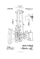
- Figure 1 shows the invention in side elevation
- Fig. 2 is a horizontal section
- F ig. 3 is a vertical section
- Fig. 4 is a sectional detail showing the pivotal mountings of certain of the poised elements of the structure.
- Fig. 5 is a side elevation of one of the supporting brackets for the scale beam, showing the manner in which the scale beam is assembled pivotally with the brackets, parts being sectioned.
- a hopper 1 preferably in the form of a truncated tetragonal pyramid, provided adjacent its upper end with an outstanding flange 2, adapted to be united by means of bolts 3, or in any other manner, with a mating flange 4, formed upon the lower end of a collar 5, adapted to be secured to the Specification of Letters Patent.
- bin or hopper 6 in which the material to be weighed, is stored.
- a closure 10 adapted to fit closely, yet slidably, against the lower end of the hopper 1.
- the lower end of the hopper 1 and the closure 10 are disposed in an are, as indicated at 11 in Fig. 1, the center from which this are is struck, being the center of-the pivot pin 8.
- the closure 10 may be equipped with a suitable handle 12, whereby the closure may be withdrawn from beneath the hopper 1, thus permitting the contents of the bin 6, to flow downwardly out of the hopper 1, into a receptacle, supported upon the weighing mechanism in a manner to be described hereinafter.
- brackets 15 are secured to the flange 2 of the hopper 1, in front of the lugs 7
- These brackets 15 are bored to receive bushings 16, in which are seated loosely, knife edge pins 17, projecting inwardly from the arms of a Y shaped yoke 18, to form a pivotal mounting for the yoke:
- the yoke 18 carries an outstanding scale beam 19, suitable connecting mechanism 20 being employed for uniting the scale beam with the yoke.
- converging arms 22 are secured to the hopper 1, above and below the scale beam 19, the arms 22 carrying, at their free eXtremities, and adjacent the free end of the scale beam 19, an annular casing 23, in which the end of the scale beam 19 is inclosed, the easing 23 being bolted, or otherwise secured to the arms 22, as shown at 2 1.
- a weight 25 Slidably mounted upon the scale beam 1.9, is a weight 25, held in place by a set screw 26 or other clamping means.
- the rear portions of the yoke 18 are equipped with openings 27 across which extend screws 28, upon which are threaded counter-poise weights 29.
- the invention further includes depending supporting members 30, positioned upon either side of the hopper 1, the supporting members being bored out to receive bushings 16, after the manner of the showing of Fig. 4. These bushings receive knife edged pins 31, projecting inwardly from the yoke 18, the pins 31 being positioned between the fulcrum pins 17 and the counter-poise weights 29.
- the lower ends of the supporting members 30 are united with a hood 32, equipped with aconical, downwardly flaring base 33, upon which rests a ring 34:.
- the ring 3% is slid upwardly upon the base 33, a bag 35 being slipped between the ring 3st and the base, whereupon the ring is permitted to drop downwardly, to engage the bag It will be seen that as the weight of material in the bag 35 increases, the upper extremity of the bag will be held the more tightly between the ring 34: and the base 33 of the hood.
- the handle 12 of the closure is engaged, the closure being swung to one side, upon its pivotal mounting S, to open the lower end of the hopper 1, whereupon the contents of the bin 6 will flow into the bag
- the weight having been clamped in a predetermined position upon the scale beam 19, by means of the set screw 26, material from the bin 6 will flow into the bag until the scale beam 19 is tilted upon its fulcrum pins 17, whereupon the member 10 may be slid manually into closed position, cutting off further flow from the bin 6 into the bag 35.
- the weight 25 may be removed entirely from the scale beam 19, whereupon a proper poise may be secured by manipulating the weights 29.
- the arms 22 and the casing 23 serve as a guard to protect the scale beam 19 from in- Copies 01' this patent may be obtained for five cents each, by addressing the Commissioner of Patents.
- the bag 35 may readily be mounted in place, and the construction is such that the greater the weight, the more firmly will the bag be held in place, the bag, however, not being likely to be torn, no matter how great be the weight which the bag supports.
- a hopper a hopper; swing rods pivotally connected with the hopper; a closure for the bottom of the hopper, carried by the swing rods, the lower end of the hopper and the closure being disposed in an arc of which the pivotal mounting of the swing rods is a center; a scale beam; a yoke connected with the scale beam and having diverging arms extended upon the outside of the swing rods; means for pivotally connecting the yoke with the hopper; suspension members pivotally connected with the yoke, and located upon the outside of the swing rods; a hood secured to the lower ends of the swing rods; and a handle secured to the closure and located between the suspension members, when the closure is extended across the bottom of the hopper.
Landscapes
- Physics & Mathematics (AREA)
- General Physics & Mathematics (AREA)
- Weight Measurement For Supplying Or Discharging Of Specified Amounts Of Material (AREA)
Description
' W. D. NASH.
SCALE.
APPLICATION FILED JAN.13, 1911.
1,024,352, Patented Apr. 23, 1912.
2 SHEETS-SHEET 1.
Wi nes Inventor by r Atto rn eys COLUMBIA PLANOGRAPH C0,, WASHINGTON, D. C.
W. D. NASH.
SCALE,
APPLICATION FILED JAN.13, 1911.
1 ,O24,352. v Patented Apr. 23, 1912.
2 BHEET8-SHEET 2.
Witnesses lnvento'i Attorneys COLUIABIA PLANOGRAPfi-CD WASHINGTON. D. c.
UNITED STATES PATENT OFFICE."
WALTER D. NASH, 0F ATLANTA, GEORGIA, ASSIGNOR TO ATLANTA UTILITY WORKS, OF ATLANTA, GEORGIA.
SCALE.
To all whom 'it may concern:
Be it known that I, WALTER DEVEREUX NASH, a citizen of the United States, residing at Atlanta, in the county of Fulton and State of Georgia, have invented a new and useful Scale, of which the following is a specification.
The object of the present invention is to provide a weighing device, adapted to be assembled with a hopper or bin to receive the contents thereof, means being provided whereby the contents of the bin may be de livered into a receptacle for weighing, there being mechanism whereby the flow of the material into the receptacle may be cut off at will.
Another object of the invention is to provide novel means for holding a bag in place upon the weighing device, to receive the contents of the hopper or bin.
A further object of the invention is to provide a weighing mechanism proper, of novel and improved construction, and to equip the same with means whereby the scale beam may be protected.
\Vith the foregoing and other objects in view which will appear as the description proceeds, the invention resides in the combination and arrangement of parts and in the details of construction hereinafter de scribed and claimed, it being understood that changes in the precise embodiment of invention herein disclosed can be made within the scope of what is claimed without de parting from the spirit of the invention.
In the drawings, Figure 1 shows the invention in side elevation; Fig. 2 is a horizontal section; F ig. 3 is a vertical section; and Fig. 4 is a sectional detail showing the pivotal mountings of certain of the poised elements of the structure. Fig. 5 is a side elevation of one of the supporting brackets for the scale beam, showing the manner in which the scale beam is assembled pivotally with the brackets, parts being sectioned.
In carrying out the invention there is provided a hopper 1, preferably in the form of a truncated tetragonal pyramid, provided adjacent its upper end with an outstanding flange 2, adapted to be united by means of bolts 3, or in any other manner, with a mating flange 4, formed upon the lower end of a collar 5, adapted to be secured to the Specification of Letters Patent.
Application filed January 13, 1911.
Patented Apr. 23, 1912.
Serial No. 602,444.
bin or hopper 6, in which the material to be weighed, is stored.
Depending from the flange 2, upon opposite sides of the hopper 1, are integrally formed lugs 7, carrying pins 8, upon which are pivoted diverging swing rods 9, carrying at their lower ends, a closure 10, adapted to fit closely, yet slidably, against the lower end of the hopper 1. The lower end of the hopper 1 and the closure 10 are disposed in an are, as indicated at 11 in Fig. 1, the center from which this are is struck, being the center of-the pivot pin 8. The closure 10 may be equipped with a suitable handle 12, whereby the closure may be withdrawn from beneath the hopper 1, thus permitting the contents of the bin 6, to flow downwardly out of the hopper 1, into a receptacle, supported upon the weighing mechanism in a manner to be described hereinafter.
By means of bolts 14, or other securing elements adapted to a like end, depending brackets 15 are secured to the flange 2 of the hopper 1, in front of the lugs 7 These brackets 15 are bored to receive bushings 16, in which are seated loosely, knife edge pins 17, projecting inwardly from the arms of a Y shaped yoke 18, to form a pivotal mounting for the yoke: The yoke 18 carries an outstanding scale beam 19, suitable connecting mechanism 20 being employed for uniting the scale beam with the yoke.
By means of bolt and lug connections 21, converging arms 22 are secured to the hopper 1, above and below the scale beam 19, the arms 22 carrying, at their free eXtremities, and adjacent the free end of the scale beam 19, an annular casing 23, in which the end of the scale beam 19 is inclosed, the easing 23 being bolted, or otherwise secured to the arms 22, as shown at 2 1.
Slidably mounted upon the scale beam 1.9, is a weight 25, held in place by a set screw 26 or other clamping means. The rear portions of the yoke 18 are equipped with openings 27 across which extend screws 28, upon which are threaded counter-poise weights 29.
The invention further includes depending supporting members 30, positioned upon either side of the hopper 1, the supporting members being bored out to receive bushings 16, after the manner of the showing of Fig. 4. These bushings receive knife edged pins 31, projecting inwardly from the yoke 18, the pins 31 being positioned between the fulcrum pins 17 and the counter-poise weights 29. The lower ends of the supporting members 30 are united with a hood 32, equipped with aconical, downwardly flaring base 33, upon which rests a ring 34:.
In practical operation, the ring 3% is slid upwardly upon the base 33, a bag 35 being slipped between the ring 3st and the base, whereupon the ring is permitted to drop downwardly, to engage the bag It will be seen that as the weight of material in the bag 35 increases, the upper extremity of the bag will be held the more tightly between the ring 34: and the base 33 of the hood. After the bag 35 has been mounted in place, the handle 12 of the closure is engaged, the closure being swung to one side, upon its pivotal mounting S, to open the lower end of the hopper 1, whereupon the contents of the bin 6 will flow into the bag The weight having been clamped in a predetermined position upon the scale beam 19, by means of the set screw 26, material from the bin 6 will flow into the bag until the scale beam 19 is tilted upon its fulcrum pins 17, whereupon the member 10 may be slid manually into closed position, cutting off further flow from the bin 6 into the bag 35.
The weight 25 may be removed entirely from the scale beam 19, whereupon a proper poise may be secured by manipulating the weights 29.
The arms 22 and the casing 23 serve as a guard to protect the scale beam 19 from in- Copies 01' this patent may be obtained for five cents each, by addressing the Commissioner of Patents.
jury, the construction being such that the scale beam cannot be struck readily, from below, from above, or from either side.
By manipulating the ring 34, the bag 35 may readily be mounted in place, and the construction is such that the greater the weight, the more firmly will the bag be held in place, the bag, however, not being likely to be torn, no matter how great be the weight which the bag supports.
Having thus described the invention what is claimed is In a device of the class described, a hopper; swing rods pivotally connected with the hopper; a closure for the bottom of the hopper, carried by the swing rods, the lower end of the hopper and the closure being disposed in an arc of which the pivotal mounting of the swing rods is a center; a scale beam; a yoke connected with the scale beam and having diverging arms extended upon the outside of the swing rods; means for pivotally connecting the yoke with the hopper; suspension members pivotally connected with the yoke, and located upon the outside of the swing rods; a hood secured to the lower ends of the swing rods; and a handle secured to the closure and located between the suspension members, when the closure is extended across the bottom of the hopper.
In testimony that I claim the foregoing as my own, I have hereto attixed my signature in the presence of two witnesses.
IVALTER D. NASH.
WVitnesses J. WAYNE Moore, HERBERT B. DAVIS.
Washington, D. C.
Priority Applications (1)
| Application Number | Priority Date | Filing Date | Title |
|---|---|---|---|
| US60244411A US1024352A (en) | 1911-01-13 | 1911-01-13 | Scale. |
Applications Claiming Priority (1)
| Application Number | Priority Date | Filing Date | Title |
|---|---|---|---|
| US60244411A US1024352A (en) | 1911-01-13 | 1911-01-13 | Scale. |
Publications (1)
| Publication Number | Publication Date |
|---|---|
| US1024352A true US1024352A (en) | 1912-04-23 |
Family
ID=3092648
Family Applications (1)
| Application Number | Title | Priority Date | Filing Date |
|---|---|---|---|
| US60244411A Expired - Lifetime US1024352A (en) | 1911-01-13 | 1911-01-13 | Scale. |
Country Status (1)
| Country | Link |
|---|---|
| US (1) | US1024352A (en) |
-
1911
- 1911-01-13 US US60244411A patent/US1024352A/en not_active Expired - Lifetime
Similar Documents
| Publication | Publication Date | Title |
|---|---|---|
| US576653A (en) | Combined match | |
| US1024352A (en) | Scale. | |
| US447532A (en) | Bin or holder for coffee | |
| US1655533A (en) | Bag filler | |
| US572504A (en) | Henry p | |
| US34998A (en) | Improvement in coal-sifters | |
| US919139A (en) | Bin-measuring apparatus. | |
| US845572A (en) | Measuring device. | |
| US830308A (en) | Combined measure and weighing device. | |
| US763560A (en) | Weighing-machine. | |
| US952587A (en) | Automatic weighing apparatus. | |
| US1279824A (en) | Machine for treating rubber and other heavy plastic material. | |
| US502265A (en) | Kobekt abercrombie | |
| US1125884A (en) | Cracker-hopper. | |
| US824606A (en) | Grain-weigher. | |
| US1058305A (en) | Automatic cut-off for package-filling machines. | |
| US1032736A (en) | Measuring-machine. | |
| US1243791A (en) | Automatic scale. | |
| US700303A (en) | Vertical grain-scale. | |
| US376683A (en) | Weighing apparatus for granular and powdered substances | |
| US748644A (en) | Automatic weighing apparatus | |
| US777026A (en) | Mail-box. | |
| US1126736A (en) | Feed mechanism for gas-generators. | |
| US1269360A (en) | Automatic scale. | |
| US392126A (en) | Wood-cutting machine |