US10242418B2 - Reconfigurable graphics processor for performance improvement - Google Patents
Reconfigurable graphics processor for performance improvement Download PDFInfo
- Publication number
- US10242418B2 US10242418B2 US13/993,696 US201113993696A US10242418B2 US 10242418 B2 US10242418 B2 US 10242418B2 US 201113993696 A US201113993696 A US 201113993696A US 10242418 B2 US10242418 B2 US 10242418B2
- Authority
- US
- United States
- Prior art keywords
- graphics processor
- power
- power gating
- performance
- gating
- Prior art date
- Legal status (The legal status is an assumption and is not a legal conclusion. Google has not performed a legal analysis and makes no representation as to the accuracy of the status listed.)
- Active, expires
Links
Images


Classifications
-
- G—PHYSICS
- G06—COMPUTING; CALCULATING OR COUNTING
- G06T—IMAGE DATA PROCESSING OR GENERATION, IN GENERAL
- G06T1/00—General purpose image data processing
- G06T1/20—Processor architectures; Processor configuration, e.g. pipelining
-
- G—PHYSICS
- G06—COMPUTING; CALCULATING OR COUNTING
- G06F—ELECTRIC DIGITAL DATA PROCESSING
- G06F1/00—Details not covered by groups G06F3/00 - G06F13/00 and G06F21/00
- G06F1/26—Power supply means, e.g. regulation thereof
-
- G—PHYSICS
- G06—COMPUTING; CALCULATING OR COUNTING
- G06F—ELECTRIC DIGITAL DATA PROCESSING
- G06F1/00—Details not covered by groups G06F3/00 - G06F13/00 and G06F21/00
- G06F1/26—Power supply means, e.g. regulation thereof
- G06F1/32—Means for saving power
- G06F1/3203—Power management, i.e. event-based initiation of a power-saving mode
- G06F1/3234—Power saving characterised by the action undertaken
- G06F1/324—Power saving characterised by the action undertaken by lowering clock frequency
-
- G—PHYSICS
- G06—COMPUTING; CALCULATING OR COUNTING
- G06F—ELECTRIC DIGITAL DATA PROCESSING
- G06F1/00—Details not covered by groups G06F3/00 - G06F13/00 and G06F21/00
- G06F1/26—Power supply means, e.g. regulation thereof
- G06F1/32—Means for saving power
- G06F1/3203—Power management, i.e. event-based initiation of a power-saving mode
- G06F1/3234—Power saving characterised by the action undertaken
- G06F1/325—Power saving in peripheral device
-
- G—PHYSICS
- G06—COMPUTING; CALCULATING OR COUNTING
- G06F—ELECTRIC DIGITAL DATA PROCESSING
- G06F1/00—Details not covered by groups G06F3/00 - G06F13/00 and G06F21/00
- G06F1/26—Power supply means, e.g. regulation thereof
- G06F1/32—Means for saving power
- G06F1/3203—Power management, i.e. event-based initiation of a power-saving mode
- G06F1/3234—Power saving characterised by the action undertaken
- G06F1/3287—Power saving characterised by the action undertaken by switching off individual functional units in the computer system
-
- G—PHYSICS
- G09—EDUCATION; CRYPTOGRAPHY; DISPLAY; ADVERTISING; SEALS
- G09G—ARRANGEMENTS OR CIRCUITS FOR CONTROL OF INDICATING DEVICES USING STATIC MEANS TO PRESENT VARIABLE INFORMATION
- G09G5/00—Control arrangements or circuits for visual indicators common to cathode-ray tube indicators and other visual indicators
- G09G5/36—Control arrangements or circuits for visual indicators common to cathode-ray tube indicators and other visual indicators characterised by the display of a graphic pattern, e.g. using an all-points-addressable [APA] memory
-
- G—PHYSICS
- G09—EDUCATION; CRYPTOGRAPHY; DISPLAY; ADVERTISING; SEALS
- G09G—ARRANGEMENTS OR CIRCUITS FOR CONTROL OF INDICATING DEVICES USING STATIC MEANS TO PRESENT VARIABLE INFORMATION
- G09G2360/00—Aspects of the architecture of display systems
- G09G2360/08—Power processing, i.e. workload management for processors involved in display operations, such as CPUs or GPUs
-
- Y—GENERAL TAGGING OF NEW TECHNOLOGICAL DEVELOPMENTS; GENERAL TAGGING OF CROSS-SECTIONAL TECHNOLOGIES SPANNING OVER SEVERAL SECTIONS OF THE IPC; TECHNICAL SUBJECTS COVERED BY FORMER USPC CROSS-REFERENCE ART COLLECTIONS [XRACs] AND DIGESTS
- Y02—TECHNOLOGIES OR APPLICATIONS FOR MITIGATION OR ADAPTATION AGAINST CLIMATE CHANGE
- Y02D—CLIMATE CHANGE MITIGATION TECHNOLOGIES IN INFORMATION AND COMMUNICATION TECHNOLOGIES [ICT], I.E. INFORMATION AND COMMUNICATION TECHNOLOGIES AIMING AT THE REDUCTION OF THEIR OWN ENERGY USE
- Y02D10/00—Energy efficient computing, e.g. low power processors, power management or thermal management
-
- Y02D10/126—
-
- Y02D10/171—
-
- Y—GENERAL TAGGING OF NEW TECHNOLOGICAL DEVELOPMENTS; GENERAL TAGGING OF CROSS-SECTIONAL TECHNOLOGIES SPANNING OVER SEVERAL SECTIONS OF THE IPC; TECHNICAL SUBJECTS COVERED BY FORMER USPC CROSS-REFERENCE ART COLLECTIONS [XRACs] AND DIGESTS
- Y02—TECHNOLOGIES OR APPLICATIONS FOR MITIGATION OR ADAPTATION AGAINST CLIMATE CHANGE
- Y02D—CLIMATE CHANGE MITIGATION TECHNOLOGIES IN INFORMATION AND COMMUNICATION TECHNOLOGIES [ICT], I.E. INFORMATION AND COMMUNICATION TECHNOLOGIES AIMING AT THE REDUCTION OF THEIR OWN ENERGY USE
- Y02D30/00—Reducing energy consumption in communication networks
- Y02D30/50—Reducing energy consumption in communication networks in wire-line communication networks, e.g. low power modes or reduced link rate
-
- Y02D50/20—
Definitions
- This relates generally to graphics processing in computer systems.
- Graphics processors run under different processing conditions. In some cases, they can run in higher power consumption modes and in lower power consumption modes. It would be desirable to obtain the maximum performance possible, given the power consumption mode that the graphics processor operates within.
- FIG. 1 is a block depiction of one embodiment of the present invention
- FIG. 2 is a flow chart for another embodiment of the present invention.
- FIG. 3 is a schematic depiction of one embodiment of the present invention.
- FIG. 4 is a hypothetical graph of performance versus power budget for one embodiment of the present invention.
- FIG. 5 is a hypothetical graph of power budget versus time for one embodiment.
- graphics processing cores automatically reconfigure themselves to increase or maximize performance in both higher and lower power envelopes by dynamically power gating portions of the graphics processing engine.
- power gating includes activating or deactivating a core portion.
- a graphics processing core typically includes a number of execution units that perform arithmetic, logic, and other operations.
- a number of samplers may be used for texture processing.
- a sampler and a number of execution units are a subslice.
- a number of subslices may be included in a particular graphics processing core, based on target performance and power budget. Subslices are combined to form a graphics processing slice.
- a graphics processing core may contain one or more slices. In a tablet graphics processing core, single slice and one, two, or three subslice designs are commonly used. Multiple slices are common in client graphics processors.
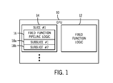
- the core 10 includes a slice number 1, labeled 14 , that may include a fixed function pipeline logic 16 and a number of subslices 18 a and 18 b . More slices and more or less subslices may be included in some embodiments. Also included in the graphics processor core is a fixed function logic 12 .
- Performance increases linearly up to a knee A (for example, around 2.5 Watts) of performance versus power dissipation, as one example.
- a knee A for example, around 2.5 Watts
- the graphics processor is operating in a frequency scaled region where graphics processor frequency can be raised without raising the operating voltage.
- graphics processor frequency is only raised if voltage is increased as well, which generally has a negative impact on power dissipation and results in a flatter plot of performance versus power dissipation than is experienced in the frequency scaled region.
- One or more of the subslices of a graphics processor core may be power gated.
- This better performance is the result of the larger configuration having significantly more leakage power and, therefore, less room for dynamic power.
- less room for dynamic power can significantly limit the frequency and performance of the larger configuration, making it look less attractive than the smaller configuration.
- a power sharing mechanism may be used to achieve efficient dynamic power gating of graphics processor subslices.
- gating subslice power consumption instead of gating subslice power consumption, the same concepts apply to dynamic power gating of any number of graphics processor slices in embodiments with more than one slice.
- Graphics processors may have a power sharing function that basically increases (or decreases) power over time, as shown in FIG. 5 .
- a graphics processor core may be assigned, by a power control unit, a power budget TDP1 at a particular lower level that forces the graphics processor to operate at a particular frequency f1 that is the maximum frequency that allows the graphics processor not to exceed its allocated power budget.
- the graphics core may operate at progressively higher frequencies.
- the power control unit knows ahead of time that the graphics processor core can be configured with a full complement of execution units and subslices or with less execution units and subslices. For example, one embodiment may include sixteen execution units and two subslices and another mode of operation may include eight execution units and one subslice.
- the graphics processor may be configured in the smaller core configuration with one of the two available subslices being power gated.
- a subslice is not simply turned off at any particular point in time, as it may be executing active threads.
- the immediate action is to block new graphics processing threads from being scheduled on that subslice. Thus, it may take some time before the threads already executing on the subslice complete and the subslice becomes idle. Only then is the subslice actually power gated in one embodiment.
- a subslice that was initially turned off gets turned on. Or, reversely, as the processor progresses from higher to lower power budgets, a subslice may be turned off (as indicated in FIG. 5 ).
- the frequency may increase or double (if one of two subslices is turned off). As a result, the performance can remain relatively stable, since the remaining subslice operates twice as fast as the two subslices.
- This frequency increase ensures a smooth (from a performance perspective) transition from the larger ungated graphics core to the smaller gated graphics core.
- the clock frequency reduces by half, to maintain overall performance at about the same level.
- the clock frequency changes described above are designed to not significantly disrupt (e.g. double or half) the overall performance of the scalable portion of the graphics core, (subslice logic shown in FIG. 1 ) at the point in time when power gating occurs.
- the act of power gating has produced a more power-efficient graphics core due to its lower leakage dissipation, this would subsequently allow the graphics core to raise its clock frequency and power dissipation to fill its allocated power budget. This would lead to increased performance, which was the ultimate goal of power gating.
- Raising or reducing clock frequency in the process of dynamic power gating as described above works well for the scalable portion of the graphics core, i.e. the subslice shown in FIG. 1 . If, however, the same clock is used by the non-scalable portion of the graphics core (e.g. the fixed function logic 12 , shown in FIG. 1 ) then changing the clock frequency may affect, and potentially limit, the performance of that logic. This would not be desirable. To avoid that, the non-scalable logic may use its own independent clock which is not affected by clock frequency changes in the scalable graphics logic.
- Switching from a larger configuration to a smaller configuration can improve performance because it provides leakage savings and makes room for more dynamic power.
- switching from the larger to the smaller configuration may potentially lead to increased dynamic power since the frequency increases correspondingly. Therefore, the transition from larger to smaller configuration may happen when the leakage savings achieved exceeds the dynamic power cost due to the corresponding frequency increase. When that condition holds, there will be a net power savings by the transition and there is room to increase the frequency even further and achieve a net performance gain.
- f8 and f16 are the frequencies of the eight and sixteen execution unit configurations at the point in time when the power gating or ungating event occurs; V8 and V16 are the operating voltages of the two graphics processing cores when the power gating event occurs; C8 and C16 are the switching capacitance of the two graphics processing cores when the power gating event occurs; Cmax8 and Cmax16 and the maximum switching capacitance of the two graphics cores for a power virus workload; and AR16 and AR8 are the application ratios of the two cores right before and after the power gating or ungating event.
- the ‘Application Ratio’ of an application is defined as the ratio of the graphics core switching capacitance when that application executes on the core over the switching capacitance of the graphics core power virus.
- the package power-sharing mechanism which may already be supported by the graphics processor, involves knowledge of the leakage power as a function of operating conditions, including die, voltage, and temperature and that is usually fused into the part, so that this information is already available. From that information, the leakage delta of the power-gated graphics core can be dynamically calculated as well, by simply scaling total leakage by the number appropriate when a subslice is power gated.
- the graphics processing core is currently configured as a sixteen execution unit, two subslice core, f16 and V16 are its current frequency and voltage and the target frequency f8 to switch to, after power gating the subslice, is then two times f16.
- the matching voltage V8 is also known ahead of time.
- the current switching capacitance, C16 can be estimated using turbo energy counters already available in some graphics processing engines.
- the maximum capacitance Cmax8 is a static quantity that is also known ahead of time and fused into the part.
- C8 or AR8 is a follows. Silicon measurements taken with different graphics workloads may show that the application ratio of a workload running on a larger graphics core is lower than the application ratio of the same workload running on a smaller graphics core by a relatively predictable scale factor, such as 0.8 ⁇ or 0.7 ⁇ , for a wide range of workloads. So, one approach is to do a post-silicon characterization of a range of applications running on the power gated or un-gated graphics cores. The average sixteen execution unit versus eight execution unit application ratio scale factor can then be calculated and may be programmed as a static application ratio scale factor. While active in sixteen execution units mode, the graphics core can dynamically estimate its current application ratio using the available turbo energy counters and then project its application ratio AR8 that it would have if it operated in eight execution units mode by using the scale factor described above.
- a relatively predictable scale factor such as 0.8 ⁇ or 0.7 ⁇
- energy monitor counters can be used to correlate (via a curve-fitting method) the values of the energy counters to not only the capacitance of the current sixteen execution unit graphics core (C 16 ) but also for the target sixteen execution unit graphics core that we will switch to after power gating occurs. Once that capacitance is estimated, equation (2) can be used to make the power gating decision. This method may be more accurate than the previous one, but may involve more detailed and time consuming post-silicon characterization of the energy monitor counters for both the 16 and 8 execution unit configurations.
- the power may be measured and, therefore, the switching capacitance or application ratio in the new eight execution unit configuration is also determined. If that turns out to be significantly higher than estimated, then the power gating decision that was taken was wrong. In such case, the decision can be reversed, transitioning back to the larger configuration. If, on the other hand, the capacitance estimation of the smaller configuration was done correctly before power gating, then the extra dynamic power measured after the transition to the smaller configuration is less than the power savings. In that case, the new configuration may be maintained and the power sharing mechanism naturally pushes to a somewhat higher frequency, resulting from the net power reduction at iso-performance, providing a performance gain. Of course, the same considerations can be used to handle power gating of multiple subslices or slices.
- FIG. 2 shows a sequence for making the power gating determining in accordance with some embodiments of the present invention.
- the sequence may be implemented in hardware, software, and/or firmware.
- it may be implemented in computer executed instructions stored in a non-transitory computer readable medium, such as a magnetic, optical, or semiconductor storage.
- one subslice is active, as indicated at block 20 .
- a check at diamond 22 determines whether the power control unit requests a new graphics processor turbo frequency. If so, a check at diamond 24 determines whether the conditions to turn on a second subslice are met. If not, the new graphics turbo frequency is set (block 26 ), as requested by the power control unit. If so, the second subslice is turned on.
- a tentative graphics processor frequency is set (block 28 ) and the decision to power gate is then validated. If the validation is successful, as determined in diamond 30 , the flow goes to state 2. If not, the subslice is power gated again, as indicated in block 32 , and the processor returns to state 1.
- a check at diamond 36 determines whether the power control unit has requested a new graphics processor turbo frequency. If so, a check at diamond 38 determines whether the conditions to turn off a subslice have been met. If not, the new graphics processor turbo frequency is set (block 40 ) as requested. Otherwise, at block 42 , thread scheduling on the target subslices is terminated. The sequence waits for the target subslice to become idle and, then when it does so, turns off the target subslice. A tentative graphics frequency is set and then the decision to power ungate is validated. If the decision is validated at diamond 44 , the flow proceeds back to state 1. Otherwise, the subslice is powered up again, as indicated in block 46 .
- the computer system 130 may include a hard drive 134 and a removable medium 136 , coupled by a bus 104 to a chipset core logic 110 .
- the computer system may be any computer system, including a smart mobile device, such as a smart phone, tablet, or a mobile Internet device.
- a keyboard and mouse 120 may be coupled to the chipset core logic via bus 108 .
- the core logic may couple to the graphics processor 112 , via a bus 105 , and the central processor 100 in one embodiment.
- the graphics processor 112 may also be coupled by a bus 106 to a frame buffer 114 .
- the frame buffer 114 may be coupled by a bus 107 to a display screen 118 .
- a graphics processor 112 may be a multi-threaded, multi-core parallel processor using single instruction multiple data (SIMD) architecture.
- SIMD single instruction multiple data
- the pertinent code may be stored in any suitable semiconductor, magnetic, or optical memory, including the main memory 132 (as indicated at 139 ) or any available memory within the graphics processor.
- the code to perform the sequence of FIG. 2 may be stored in a non-transitory machine or computer readable medium, such as the memory 132 , and/or the graphics processor 112 , and/or the central processor 100 and may be executed by the processor 100 and/or the graphics processor 112 in one embodiment.
- graphics processing techniques described herein may be implemented in various hardware architectures. For example, graphics functionality may be integrated within a chipset. Alternatively, a discrete graphics processor may be used. As still another embodiment, the graphics functions may be implemented by a general purpose processor, including a multicore processor.
- references throughout this specification to “one embodiment” or “an embodiment” mean that a particular feature, structure, or characteristic described in connection with the embodiment is included in at least one implementation encompassed within the present invention. Thus, appearances of the phrase “one embodiment” or “in an embodiment” are not necessarily referring to the same embodiment. Furthermore, the particular features, structures, or characteristics may be instituted in other suitable forms other than the particular embodiment illustrated and all such forms may be encompassed within the claims of the present application.
Landscapes
- Engineering & Computer Science (AREA)
- Theoretical Computer Science (AREA)
- Physics & Mathematics (AREA)
- General Physics & Mathematics (AREA)
- General Engineering & Computer Science (AREA)
- Computer Hardware Design (AREA)
- Computing Systems (AREA)
- Power Sources (AREA)
Abstract
Power gating a portion of a graphics processor may be used to improve performance or to achieve a power budget. A processor granularity, such as a slice or subslice, may be gated.
Description
This relates generally to graphics processing in computer systems.
Graphics processors run under different processing conditions. In some cases, they can run in higher power consumption modes and in lower power consumption modes. It would be desirable to obtain the maximum performance possible, given the power consumption mode that the graphics processor operates within.
In some embodiments, graphics processing cores automatically reconfigure themselves to increase or maximize performance in both higher and lower power envelopes by dynamically power gating portions of the graphics processing engine. As used herein, power gating includes activating or deactivating a core portion.
While an example will be provided using a tablet computer graphics processor, the same concepts apply to any graphics processor.
A graphics processing core typically includes a number of execution units that perform arithmetic, logic, and other operations. A number of samplers may be used for texture processing. A sampler and a number of execution units are a subslice. A number of subslices may be included in a particular graphics processing core, based on target performance and power budget. Subslices are combined to form a graphics processing slice. A graphics processing core may contain one or more slices. In a tablet graphics processing core, single slice and one, two, or three subslice designs are commonly used. Multiple slices are common in client graphics processors.
Thus, referring to FIG. 1 , showing a typical graphics processor core, the core 10 includes a slice number 1, labeled 14, that may include a fixed function pipeline logic 16 and a number of subslices 18 a and 18 b. More slices and more or less subslices may be included in some embodiments. Also included in the graphics processor core is a fixed function logic 12.
The power and performance characteristics of one, two, and three subslice designs are different, as indicated in FIG. 4 . Performance increases linearly up to a knee A (for example, around 2.5 Watts) of performance versus power dissipation, as one example. Below this knee, the graphics processor is operating in a frequency scaled region where graphics processor frequency can be raised without raising the operating voltage. Above the knee, graphics processor frequency is only raised if voltage is increased as well, which generally has a negative impact on power dissipation and results in a flatter plot of performance versus power dissipation than is experienced in the frequency scaled region.
One or more of the subslices of a graphics processor core may be power gated. Generally, the more subslices, the higher performance, but the performance gap reduces as the available power budget reduces and there may be a point B in FIG. 4 (for example, at around 1.5 Watts) wherein the single subslice configuration performs better than a two subslice configuration. This better performance is the result of the larger configuration having significantly more leakage power and, therefore, less room for dynamic power. In a lower power budget, less room for dynamic power can significantly limit the frequency and performance of the larger configuration, making it look less attractive than the smaller configuration.
In some embodiments, a power sharing mechanism may be used to achieve efficient dynamic power gating of graphics processor subslices. Of course, instead of gating subslice power consumption, the same concepts apply to dynamic power gating of any number of graphics processor slices in embodiments with more than one slice.
Graphics processors may have a power sharing function that basically increases (or decreases) power over time, as shown in FIG. 5 . At a particular point in time t1, a graphics processor core may be assigned, by a power control unit, a power budget TDP1 at a particular lower level that forces the graphics processor to operate at a particular frequency f1 that is the maximum frequency that allows the graphics processor not to exceed its allocated power budget. As the power budget is increased over time, the graphics core may operate at progressively higher frequencies.
With subslice power gating, the power control unit knows ahead of time that the graphics processor core can be configured with a full complement of execution units and subslices or with less execution units and subslices. For example, one embodiment may include sixteen execution units and two subslices and another mode of operation may include eight execution units and one subslice. When the power budget available to the graphics processor is small, the graphics processor may be configured in the smaller core configuration with one of the two available subslices being power gated.
Generally, a subslice is not simply turned off at any particular point in time, as it may be executing active threads. When the power control unit makes the determination that a subslice should be power gated, the immediate action is to block new graphics processing threads from being scheduled on that subslice. Thus, it may take some time before the threads already executing on the subslice complete and the subslice becomes idle. Only then is the subslice actually power gated in one embodiment.
With power gating, as power budget is progressively increased, at some point a subslice that was initially turned off gets turned on. Or, reversely, as the processor progresses from higher to lower power budgets, a subslice may be turned off (as indicated in FIG. 5 ).
When a subslice is turned off, the frequency may increase or double (if one of two subslices is turned off). As a result, the performance can remain relatively stable, since the remaining subslice operates twice as fast as the two subslices. This frequency increase ensures a smooth (from a performance perspective) transition from the larger ungated graphics core to the smaller gated graphics core. Reversely, when a subslice is ungated and we transition to a two-subslice graphics core, the clock frequency reduces by half, to maintain overall performance at about the same level.
The clock frequency changes described above are designed to not significantly disrupt (e.g. double or half) the overall performance of the scalable portion of the graphics core, (subslice logic shown in FIG. 1 ) at the point in time when power gating occurs. However, if the act of power gating has produced a more power-efficient graphics core due to its lower leakage dissipation, this would subsequently allow the graphics core to raise its clock frequency and power dissipation to fill its allocated power budget. This would lead to increased performance, which was the ultimate goal of power gating.
On the other hand, when the power budget allocated to the graphics core increases and allows for adding a subslice, reducing the clock frequency by half will initially preserve the same performance. However, given the increased graphics power budget, the graphics core will be then allowed to also raise its frequency, which will bring the desired result of raising performance.
Raising or reducing clock frequency in the process of dynamic power gating as described above works well for the scalable portion of the graphics core, i.e. the subslice shown in FIG. 1 . If, however, the same clock is used by the non-scalable portion of the graphics core (e.g. the fixed function logic 12, shown in FIG. 1 ) then changing the clock frequency may affect, and potentially limit, the performance of that logic. This would not be desirable. To avoid that, the non-scalable logic may use its own independent clock which is not affected by clock frequency changes in the scalable graphics logic.
Switching from a larger configuration to a smaller configuration can improve performance because it provides leakage savings and makes room for more dynamic power. At the same time, switching from the larger to the smaller configuration may potentially lead to increased dynamic power since the frequency increases correspondingly. Therefore, the transition from larger to smaller configuration may happen when the leakage savings achieved exceeds the dynamic power cost due to the corresponding frequency increase. When that condition holds, there will be a net power savings by the transition and there is room to increase the frequency even further and achieve a net performance gain.
Thus, to give an example, with a sixteen execution unit, two subslice unit transitioning to an eight execution unit, one subslice unit as a result of power gating, the following Leakage Delta (LD) equations apply:
LD>f 8 *C 8 V 8 2 −f 16 *C 16 V 16 2 (1)
LD>f 8 *AR 8 *Cmax8 *V 8 2 −f 16 V 16 2 (2)
LD>f 8 *C 8 V 8 2 −f 16 *C 16 V 16 2 (1)
LD>f 8 *AR 8 *Cmax8 *V 8 2 −f 16 V 16 2 (2)
where f8 and f16 are the frequencies of the eight and sixteen execution unit configurations at the point in time when the power gating or ungating event occurs; V8 and V16 are the operating voltages of the two graphics processing cores when the power gating event occurs; C8 and C16 are the switching capacitance of the two graphics processing cores when the power gating event occurs; Cmax8 and Cmax16 and the maximum switching capacitance of the two graphics cores for a power virus workload; and AR16 and AR8 are the application ratios of the two cores right before and after the power gating or ungating event. The ‘Application Ratio’ of an application is defined as the ratio of the graphics core switching capacitance when that application executes on the core over the switching capacitance of the graphics core power virus.
These equations may be used to make the decision to initiate subslice power gating or not. The package power-sharing mechanism, which may already be supported by the graphics processor, involves knowledge of the leakage power as a function of operating conditions, including die, voltage, and temperature and that is usually fused into the part, so that this information is already available. From that information, the leakage delta of the power-gated graphics core can be dynamically calculated as well, by simply scaling total leakage by the number appropriate when a subslice is power gated.
If the graphics processing core is currently configured as a sixteen execution unit, two subslice core, f16 and V16 are its current frequency and voltage and the target frequency f8 to switch to, after power gating the subslice, is then two times f16. The matching voltage V8 is also known ahead of time. The current switching capacitance, C16, can be estimated using turbo energy counters already available in some graphics processing engines. The maximum capacitance Cmax8 is a static quantity that is also known ahead of time and fused into the part.
Thus, the only quantities in the above two equations that are not known and cannot be directly calculated using the existing power-sharing infrastructure is the target switching capacitance C8 and the target application ratio AR8 of the smaller configuration that we want to switch to. These two quantities are essentially equivalent since one can be calculated from the other (C8=AR8*Cmax8).
One way to estimate C8 or AR8 is a follows. Silicon measurements taken with different graphics workloads may show that the application ratio of a workload running on a larger graphics core is lower than the application ratio of the same workload running on a smaller graphics core by a relatively predictable scale factor, such as 0.8× or 0.7×, for a wide range of workloads. So, one approach is to do a post-silicon characterization of a range of applications running on the power gated or un-gated graphics cores. The average sixteen execution unit versus eight execution unit application ratio scale factor can then be calculated and may be programmed as a static application ratio scale factor. While active in sixteen execution units mode, the graphics core can dynamically estimate its current application ratio using the available turbo energy counters and then project its application ratio AR8 that it would have if it operated in eight execution units mode by using the scale factor described above.
Alternatively, energy monitor counters can be used to correlate (via a curve-fitting method) the values of the energy counters to not only the capacitance of the current sixteen execution unit graphics core (C16) but also for the target sixteen execution unit graphics core that we will switch to after power gating occurs. Once that capacitance is estimated, equation (2) can be used to make the power gating decision. This method may be more accurate than the previous one, but may involve more detailed and time consuming post-silicon characterization of the energy monitor counters for both the 16 and 8 execution unit configurations.
Once the decision to power gate has been taken in the transition from sixteen to eight execution units has been completed, the power may be measured and, therefore, the switching capacitance or application ratio in the new eight execution unit configuration is also determined. If that turns out to be significantly higher than estimated, then the power gating decision that was taken was wrong. In such case, the decision can be reversed, transitioning back to the larger configuration. If, on the other hand, the capacitance estimation of the smaller configuration was done correctly before power gating, then the extra dynamic power measured after the transition to the smaller configuration is less than the power savings. In that case, the new configuration may be maintained and the power sharing mechanism naturally pushes to a somewhat higher frequency, resulting from the net power reduction at iso-performance, providing a performance gain. Of course, the same considerations can be used to handle power gating of multiple subslices or slices.
In the case of deactivating a core portion, we may be transitioning from an eight execution unit graphics core to a sixteen execution unit graphics core in some cases. We can use equations (1) and (2) to ensure that the extra leakage of the sixteen execution unit graphics core will be lower than the dynamic power savings achieved by reducing the clock frequency by half. In that case, clock frequency can be raised which will increase performance.
In state 1 in this example, one subslice is active, as indicated at block 20. A check at diamond 22 determines whether the power control unit requests a new graphics processor turbo frequency. If so, a check at diamond 24 determines whether the conditions to turn on a second subslice are met. If not, the new graphics turbo frequency is set (block 26), as requested by the power control unit. If so, the second subslice is turned on. A tentative graphics processor frequency is set (block 28) and the decision to power gate is then validated. If the validation is successful, as determined in diamond 30, the flow goes to state 2. If not, the subslice is power gated again, as indicated in block 32, and the processor returns to state 1.
In state 2, with two subslices active, as indicated at block 34, a check at diamond 36 determines whether the power control unit has requested a new graphics processor turbo frequency. If so, a check at diamond 38 determines whether the conditions to turn off a subslice have been met. If not, the new graphics processor turbo frequency is set (block 40) as requested. Otherwise, at block 42, thread scheduling on the target subslices is terminated. The sequence waits for the target subslice to become idle and, then when it does so, turns off the target subslice. A tentative graphics frequency is set and then the decision to power ungate is validated. If the decision is validated at diamond 44, the flow proceeds back to state 1. Otherwise, the subslice is powered up again, as indicated in block 46.
The computer system 130, shown in FIG. 3 , may include a hard drive 134 and a removable medium 136, coupled by a bus 104 to a chipset core logic 110. The computer system may be any computer system, including a smart mobile device, such as a smart phone, tablet, or a mobile Internet device. A keyboard and mouse 120, or other conventional components, may be coupled to the chipset core logic via bus 108. The core logic may couple to the graphics processor 112, via a bus 105, and the central processor 100 in one embodiment. The graphics processor 112 may also be coupled by a bus 106 to a frame buffer 114. The frame buffer 114 may be coupled by a bus 107 to a display screen 118. In one embodiment, a graphics processor 112 may be a multi-threaded, multi-core parallel processor using single instruction multiple data (SIMD) architecture.
In the case of a software implementation, the pertinent code may be stored in any suitable semiconductor, magnetic, or optical memory, including the main memory 132 (as indicated at 139) or any available memory within the graphics processor. Thus, in one embodiment, the code to perform the sequence of FIG. 2 may be stored in a non-transitory machine or computer readable medium, such as the memory 132, and/or the graphics processor 112, and/or the central processor 100 and may be executed by the processor 100 and/or the graphics processor 112 in one embodiment.
The graphics processing techniques described herein may be implemented in various hardware architectures. For example, graphics functionality may be integrated within a chipset. Alternatively, a discrete graphics processor may be used. As still another embodiment, the graphics functions may be implemented by a general purpose processor, including a multicore processor.
References throughout this specification to “one embodiment” or “an embodiment” mean that a particular feature, structure, or characteristic described in connection with the embodiment is included in at least one implementation encompassed within the present invention. Thus, appearances of the phrase “one embodiment” or “in an embodiment” are not necessarily referring to the same embodiment. Furthermore, the particular features, structures, or characteristics may be instituted in other suitable forms other than the particular embodiment illustrated and all such forms may be encompassed within the claims of the present application.
While the present invention has been described with respect to a limited number of embodiments, those skilled in the art will appreciate numerous modifications and variations therefrom. It is intended that the appended claims cover all such modifications and variations as fall within the true spirit and scope of this present invention.
Claims (27)
1. A method comprising:
determining a performance measure of a graphics processor in a larger configuration without power gating;
power gating one of two hardware portions of a graphics processor;
determining performance of the graphics processor with power gating;
determining in the graphics processor if the graphics processor performance was improved by power gating compared to graphics processor performance without power gating to determine the effect of graphics processor power gating by comparing performance of the graphics processor with and without any power gating; and
transitioning to a smaller configuration, with power gating, only if leakage savings of the smaller configuration exceed dynamic power cost due to increased frequency operation in the smaller configuration.
2. The method of claim 1 including power gating a slice.
3. The method of claim 1 including power gating a subslice.
4. The method of claim 1 including changing operating frequency after power gating.
5. The method of claim 1 including power gating the portion off only after all pending tasks on the portion have completed.
6. The method of claim 1 including power gating for power budgeting.
7. The method of claim 1 including checking power budget after power gating.
8. The method of claim 1 including determining target switching capacitance and target application ratio.
9. The method of claim 8 including using one of silicon measurements or energy monitor counters.
10. A non-transitory computer readable medium storing instructions for execution by a computer to:
determining a performance measure of a graphics processor in a larger configuration without power gating;
power gating one of two hardware portions of a graphics processor;
determining performance of the graphics processor with power gating;
determining in the graphics processor if the graphics processor performance was improved by power gating compared to graphics processor performance without power gating to determine the effect of graphics processor power gating by comparing performance of the graphics processor with and without any power gating; and
transitioning to a smaller configuration, with power gating, only if leakage savings of the smaller configuration exceed dynamic power cost due to increased frequency operation in the smaller configuration.
11. The medium of claim 10 further storing instructions to power gate a slice.
12. The medium of claim 10 further storing instructions to power gate a subslice.
13. The medium of claim 10 further storing instructions to change operating frequency after power gating.
14. The medium of claim 10 further storing instructions to power gate the portion off only after all pending tasks on the portion have completed.
15. The medium of claim 10 further storing instructions to power gate for power budgeting.
16. The medium of claim 10 further storing instructions to check power budget after power gating.
17. The medium of claim 10 further storing instructions to determine target switching capacitance and target application ratio.
18. The medium of claim 17 further storing instructions to use one of silicon measurements or energy monitor counters.
19. A graphics processor comprising:
first and second independently gateable hardware portions of the graphics processor; and
logic to power gate one of two portions of a graphics processor and to determine a performance measure of a graphics processor in a larger configuration without power gating, determine performance of the graphics processor with power gating, determine if the graphics processor performance was improved by power gating compared to performance without power gating to determine the effect of graphics processor power gating by comparing performance of the graphics processor with and without any power gating and transition to a smaller configuration, with power gating, only if leakage savings of the smaller configuration exceed dynamic power cost due to increased frequency operation in the smaller configuration.
20. The graphics processor of claim 19 , said logic to power gate a slice.
21. The graphics processor of claim 19 , said logic to power gate a subslice.
22. The graphics processor of claim 19 , said logic to change operating frequency after power gating.
23. The graphics processor of claim 19 , said logic to power gate the portion off only after all pending tasks on the portion have completed.
24. The graphics processor of claim 19 , said logic to power gate for power budgeting.
25. The graphics processor of claim 19 , said logic to check power budget after power gating.
26. The graphics processor of claim 19 , said logic to determine target switching capacitance and target application ratio.
27. The graphics processor of claim 26 , said logic to use one of silicon measurements or energy monitor counters.
Applications Claiming Priority (1)
| Application Number | Priority Date | Filing Date | Title |
|---|---|---|---|
| PCT/US2011/061738 WO2013077848A1 (en) | 2011-11-21 | 2011-11-21 | Reconfigurable graphics processor for performance improvement |
Publications (2)
| Publication Number | Publication Date |
|---|---|
| US20130286026A1 US20130286026A1 (en) | 2013-10-31 |
| US10242418B2 true US10242418B2 (en) | 2019-03-26 |
Family
ID=48470158
Family Applications (1)
| Application Number | Title | Priority Date | Filing Date |
|---|---|---|---|
| US13/993,696 Active 2032-06-30 US10242418B2 (en) | 2011-11-21 | 2011-11-21 | Reconfigurable graphics processor for performance improvement |
Country Status (5)
| Country | Link |
|---|---|
| US (1) | US10242418B2 (en) |
| EP (2) | EP2783267A4 (en) |
| CN (2) | CN108509021B (en) |
| TW (1) | TWI477955B (en) |
| WO (1) | WO2013077848A1 (en) |
Cited By (2)
| Publication number | Priority date | Publication date | Assignee | Title |
|---|---|---|---|---|
| US11514551B2 (en) | 2020-09-25 | 2022-11-29 | Intel Corporation | Configuration profiles for graphics processing unit |
| US20230104685A1 (en) * | 2020-03-27 | 2023-04-06 | Intel Corporation | Power management circuitry |
Families Citing this family (8)
| Publication number | Priority date | Publication date | Assignee | Title |
|---|---|---|---|---|
| US9037889B2 (en) * | 2012-09-28 | 2015-05-19 | Intel Corporation | Apparatus and method for determining the number of execution cores to keep active in a processor |
| US9703364B2 (en) * | 2012-09-29 | 2017-07-11 | Intel Corporation | Rotational graphics sub-slice and execution unit power down to improve power performance efficiency |
| US10088891B2 (en) * | 2013-09-23 | 2018-10-02 | Cornell University | Multi-core computer processor based on a dynamic core-level power management for enhanced overall power efficiency |
| US9563263B2 (en) | 2013-12-19 | 2017-02-07 | Intel Corporation | Graphics processor sub-domain voltage regulation |
| US10025367B2 (en) | 2014-08-19 | 2018-07-17 | Intel Corporation | Dynamic scaling of graphics processor execution resources |
| US9952651B2 (en) * | 2015-07-31 | 2018-04-24 | International Business Machines Corporation | Deterministic current based frequency optimization of processor chip |
| US9568982B1 (en) | 2015-07-31 | 2017-02-14 | International Business Machines Corporation | Management of core power state transition in a microprocessor |
| US20210136680A1 (en) * | 2020-12-11 | 2021-05-06 | Intel Corporation | Energy aware network slicing |
Citations (24)
| Publication number | Priority date | Publication date | Assignee | Title |
|---|---|---|---|---|
| US20050120254A1 (en) * | 2001-03-22 | 2005-06-02 | Sony Computer Entertainment Inc. | Power management for processing modules |
| CN200959110Y (en) | 2006-08-08 | 2007-10-10 | 杨帅 | Combined alternating operating notebook computer of double-graphic processor |
| US20090001814A1 (en) * | 2007-06-27 | 2009-01-01 | Vijay Subramaniam | Power gating for multimedia processing power management |
| US20090204835A1 (en) | 2008-02-11 | 2009-08-13 | Nvidia Corporation | Use methods for power optimization using an integrated circuit having power domains and partitions |
| CN101536080A (en) | 2006-05-30 | 2009-09-16 | Ati技术Ulc公司 | Device having multiple graphics subsystems and reduced power consumption mode, software and methods |
| CN101604199A (en) | 2008-05-16 | 2009-12-16 | 英特尔公司 | The determining based on efficient of operating characteristic |
| US7664255B2 (en) | 2007-03-30 | 2010-02-16 | Thought Development Inc. | Hands free aural device holder |
| US20100131786A1 (en) | 2006-06-09 | 2010-05-27 | Vivante Corporation | Single Chip 3D and 2D Graphics Processor with Embedded Memory and Multiple Levels of Power Controls |
| US20100174933A1 (en) | 2009-01-07 | 2010-07-08 | Lee-Chung Lu | System and Method for Reducing Processor Power Consumption |
| US7802118B1 (en) | 2006-12-21 | 2010-09-21 | Nvidia Corporation | Functional block level clock-gating within a graphics processor |
| US20100295852A1 (en) * | 2009-05-25 | 2010-11-25 | Chia-Lin Yang | Graphics processing system with power-gating control function, power-gating control method, and computer program products thereof |
| US20110060928A1 (en) * | 2009-09-09 | 2011-03-10 | Ati Technologies Ulc | Method and Apparatus for Disabling a Device |
| US20110115567A1 (en) | 2009-11-13 | 2011-05-19 | Pantas Sutardja | Clock turn-on strategy for power management |
| US20110213950A1 (en) | 2008-06-11 | 2011-09-01 | John George Mathieson | System and Method for Power Optimization |
| US20110239016A1 (en) * | 2010-03-25 | 2011-09-29 | International Business Machines Corporation | Power Management in a Multi-Processor Computer System |
| US20110291746A1 (en) * | 2010-05-27 | 2011-12-01 | Advanced Micro Devices, Inc. | Realtime power management of integrated circuits |
| US20120013627A1 (en) * | 2010-07-13 | 2012-01-19 | Advanced Micro Devices, Inc. | DYNAMIC CONTROL OF SIMDs |
| US20120102344A1 (en) * | 2010-10-21 | 2012-04-26 | Andrej Kocev | Function based dynamic power control |
| US20120119816A1 (en) * | 2010-11-17 | 2012-05-17 | Rogers Aaron S | Variable-width power gating module |
| US20120159496A1 (en) * | 2010-12-20 | 2012-06-21 | Saurabh Dighe | Performing Variation-Aware Profiling And Dynamic Core Allocation For A Many-Core Processor |
| US20120185703A1 (en) * | 2011-01-14 | 2012-07-19 | Machnicki Erik P | Coordinating Performance Parameters in Multiple Circuits |
| US20130015904A1 (en) * | 2010-03-22 | 2013-01-17 | Freescale Semiconductor, Inc. | Power gating control module, integrated circuit device, signal processing system, electronic device, and method therefor |
| US8542054B2 (en) * | 2011-10-31 | 2013-09-24 | Apple Inc. | Power switch acceleration scheme for fast wakeup |
| US9035956B1 (en) | 2012-05-08 | 2015-05-19 | Apple Inc. | Graphics power control with efficient power usage during stop |
Family Cites Families (6)
| Publication number | Priority date | Publication date | Assignee | Title |
|---|---|---|---|---|
| US7137117B2 (en) * | 2000-06-02 | 2006-11-14 | Microsoft Corporation | Dynamically variable idle time thread scheduling |
| US8397090B2 (en) * | 2006-12-08 | 2013-03-12 | Intel Corporation | Operating integrated circuit logic blocks at independent voltages with single voltage supply |
| DE102008004366A1 (en) * | 2008-01-15 | 2009-07-16 | Robert Bosch Gmbh | Drive train arrangement of a vehicle and method for controlling the operation of a drive train arrangement of a vehicle |
| WO2010023442A2 (en) * | 2008-08-26 | 2010-03-04 | The University Court Of The University Of Glasgow | Uses of electromagnetic interference patterns |
| CN101727172B (en) * | 2008-10-27 | 2012-12-19 | 联想(北京)有限公司 | Method and device for measuring process consumption of computer, and computer system |
| US8864005B2 (en) * | 2010-07-16 | 2014-10-21 | Corning Incorporated | Methods for scribing and separating strengthened glass substrates |
-
2011
- 2011-11-21 EP EP11876149.3A patent/EP2783267A4/en not_active Withdrawn
- 2011-11-21 US US13/993,696 patent/US10242418B2/en active Active
- 2011-11-21 WO PCT/US2011/061738 patent/WO2013077848A1/en active Application Filing
- 2011-11-21 CN CN201810325284.XA patent/CN108509021B/en active Active
- 2011-11-21 EP EP16153494.6A patent/EP3037910B1/en active Active
- 2011-11-21 CN CN201180074955.6A patent/CN103959196A/en active Pending
-
2012
- 2012-11-20 TW TW101143230A patent/TWI477955B/en active
Patent Citations (27)
| Publication number | Priority date | Publication date | Assignee | Title |
|---|---|---|---|---|
| US20050120254A1 (en) * | 2001-03-22 | 2005-06-02 | Sony Computer Entertainment Inc. | Power management for processing modules |
| CN101536080A (en) | 2006-05-30 | 2009-09-16 | Ati技术Ulc公司 | Device having multiple graphics subsystems and reduced power consumption mode, software and methods |
| US20100131786A1 (en) | 2006-06-09 | 2010-05-27 | Vivante Corporation | Single Chip 3D and 2D Graphics Processor with Embedded Memory and Multiple Levels of Power Controls |
| CN200959110Y (en) | 2006-08-08 | 2007-10-10 | 杨帅 | Combined alternating operating notebook computer of double-graphic processor |
| US7802118B1 (en) | 2006-12-21 | 2010-09-21 | Nvidia Corporation | Functional block level clock-gating within a graphics processor |
| US7664255B2 (en) | 2007-03-30 | 2010-02-16 | Thought Development Inc. | Hands free aural device holder |
| US20090001814A1 (en) * | 2007-06-27 | 2009-01-01 | Vijay Subramaniam | Power gating for multimedia processing power management |
| CN101802751A (en) | 2007-06-27 | 2010-08-11 | 高通股份有限公司 | Power gating for multimedia processing power management |
| US20090204835A1 (en) | 2008-02-11 | 2009-08-13 | Nvidia Corporation | Use methods for power optimization using an integrated circuit having power domains and partitions |
| CN101604199A (en) | 2008-05-16 | 2009-12-16 | 英特尔公司 | The determining based on efficient of operating characteristic |
| US20110213950A1 (en) | 2008-06-11 | 2011-09-01 | John George Mathieson | System and Method for Power Optimization |
| US20100174933A1 (en) | 2009-01-07 | 2010-07-08 | Lee-Chung Lu | System and Method for Reducing Processor Power Consumption |
| TW201042573A (en) | 2009-05-25 | 2010-12-01 | Inst Information Industry | Graphics processing system with power-gating function, power-gating method, and computer program products thereof |
| US20100295852A1 (en) * | 2009-05-25 | 2010-11-25 | Chia-Lin Yang | Graphics processing system with power-gating control function, power-gating control method, and computer program products thereof |
| US8316255B2 (en) | 2009-09-09 | 2012-11-20 | Ati Technologies Ulc | Method and apparatus for responding to signals from a disabling device while in a disabled state |
| US20110060928A1 (en) * | 2009-09-09 | 2011-03-10 | Ati Technologies Ulc | Method and Apparatus for Disabling a Device |
| US20110115567A1 (en) | 2009-11-13 | 2011-05-19 | Pantas Sutardja | Clock turn-on strategy for power management |
| US20130015904A1 (en) * | 2010-03-22 | 2013-01-17 | Freescale Semiconductor, Inc. | Power gating control module, integrated circuit device, signal processing system, electronic device, and method therefor |
| US20110239016A1 (en) * | 2010-03-25 | 2011-09-29 | International Business Machines Corporation | Power Management in a Multi-Processor Computer System |
| US20110291746A1 (en) * | 2010-05-27 | 2011-12-01 | Advanced Micro Devices, Inc. | Realtime power management of integrated circuits |
| US20120013627A1 (en) * | 2010-07-13 | 2012-01-19 | Advanced Micro Devices, Inc. | DYNAMIC CONTROL OF SIMDs |
| US20120102344A1 (en) * | 2010-10-21 | 2012-04-26 | Andrej Kocev | Function based dynamic power control |
| US20120119816A1 (en) * | 2010-11-17 | 2012-05-17 | Rogers Aaron S | Variable-width power gating module |
| US20120159496A1 (en) * | 2010-12-20 | 2012-06-21 | Saurabh Dighe | Performing Variation-Aware Profiling And Dynamic Core Allocation For A Many-Core Processor |
| US20120185703A1 (en) * | 2011-01-14 | 2012-07-19 | Machnicki Erik P | Coordinating Performance Parameters in Multiple Circuits |
| US8542054B2 (en) * | 2011-10-31 | 2013-09-24 | Apple Inc. | Power switch acceleration scheme for fast wakeup |
| US9035956B1 (en) | 2012-05-08 | 2015-05-19 | Apple Inc. | Graphics power control with efficient power usage during stop |
Non-Patent Citations (18)
| Title |
|---|
| China State Intellectual Property Office 1st office action in corresponding CN application No. 201180074955.6 dated Oct. 19, 2015 (10 page) [no English translation]. |
| China State Intellectual Property Office 2nd office action in corresponding CN application No. 201180074955.6 dated Jun. 2, 2016 (11 pages) [no English translation]. |
| China State Intellectual Property Office, office action in corresponding CN application No. 201180074955.6 dated Dec. 2, 2016 (10 pages) [no English translation]. |
| EP Office Action in corresponding EP 11 876 149.3 dated Nov. 7, 2017 (5 pages). |
| EP office action in corresponding EP application No. 11876149.3 dated Jun. 8, 2015. |
| EP office action in corresponding EP application No. 16153494.6 dated Mar. 14, 2016. |
| EP Search report in corresponding application EP 11876149 dated May 28, 2015 (6 pages). |
| European Patent Office issued supplemental search report in corresponding divisional application No. EP16153494 dated Mar. 4, 2016 (7 pages). |
| International Preliminary Report on Patentability dated Jun. 5, 2014 issued in PCT/US2011/061738 (2 pages). |
| Li, Ching Yeo, et al., "Dynamic Power Gating Implementation," Apr. 2011 (from Internet-http://downloadintel.com/embedded/processor/whitepaper/325293.pdf). |
| Li, Ching Yeo, et al., "Dynamic Power Gating Implementation," Apr. 2011 (from Internet—http://downloadintel.com/embedded/processor/whitepaper/325293.pdf). |
| Office Action dated Jun. 27, 2014 by the European Patent Office in application No. 11876149.3-1959 (3 pages). |
| PCT International Search Report and Written Opinion issued in corresponding PCT/US2011/061738 dated Jul. 31, 2012 (10 pages). |
| U.S. office action in corresponding U.S. Appl. No. 14/959,455 dated Jul. 28, 2016. |
| U.S. office action in corresponding U.S. Appl. No. 14/959,455 dated Mar. 11, 2016. |
| U.S. office action in corresponding U.S. Appl. No. 14/959,455 dated Nov. 16, 2016. |
| Written Opinion of International Searching Authority dated Jul. 31, 2012 issued in PCT/US2011/061738 (5 pages). |
| Yo, L., et al., "Dynamic Power Gating Implementation", Apr. 2011; http://www.intel.com/content/dam/www/public/us/en/documents/white-papers/emgd-dynamic-power-gating-paper.pdf, (14 pages). |
Cited By (2)
| Publication number | Priority date | Publication date | Assignee | Title |
|---|---|---|---|---|
| US20230104685A1 (en) * | 2020-03-27 | 2023-04-06 | Intel Corporation | Power management circuitry |
| US11514551B2 (en) | 2020-09-25 | 2022-11-29 | Intel Corporation | Configuration profiles for graphics processing unit |
Also Published As
| Publication number | Publication date |
|---|---|
| EP3037910B1 (en) | 2020-04-01 |
| EP2783267A4 (en) | 2015-07-08 |
| WO2013077848A1 (en) | 2013-05-30 |
| TW201337527A (en) | 2013-09-16 |
| CN108509021A (en) | 2018-09-07 |
| CN103959196A (en) | 2014-07-30 |
| EP3037910A1 (en) | 2016-06-29 |
| CN108509021B (en) | 2021-11-09 |
| EP2783267A1 (en) | 2014-10-01 |
| US20130286026A1 (en) | 2013-10-31 |
| TWI477955B (en) | 2015-03-21 |
Similar Documents
| Publication | Publication Date | Title |
|---|---|---|
| US10242418B2 (en) | Reconfigurable graphics processor for performance improvement | |
| US9354689B2 (en) | Providing energy efficient turbo operation of a processor | |
| US9348594B2 (en) | Core switching acceleration in asymmetric multiprocessor system | |
| JP6130296B2 (en) | Dynamic enabling and disabling of SIMD units in graphics processors | |
| KR101471303B1 (en) | Device and method of power management for graphic processing unit | |
| US20120297232A1 (en) | Adjusting the clock frequency of a processing unit in real-time based on a frequency sensitivity value | |
| US20120192200A1 (en) | Load Balancing in Heterogeneous Computing Environments | |
| US20140019723A1 (en) | Binary translation in asymmetric multiprocessor system | |
| JP2018533112A (en) | GPU workload characterization and power management using command stream hints | |
| US9563259B2 (en) | Apparatus and method for activating and shutting down individual enhanced pipeline stages based on stage priority and performance requirements | |
| US10242652B2 (en) | Reconfigurable graphics processor for performance improvement | |
| Sahin et al. | On the impacts of greedy thermal management in mobile devices | |
| US20180342227A1 (en) | Performance-Based Graphics Processing Unit Power Management | |
| Albers | Algorithms for energy saving | |
| KR20140005808A (en) | System and method for power management for a processing unit | |
| US8843775B2 (en) | Energy optimization techniques in a computing system | |
| Zhang et al. | Dynamic core scaling: Trading off performance and energy beyond DVFS | |
| CN105573473B (en) | Reconfigurable patterns processor for performance improvement | |
| US11953965B2 (en) | Adaptive power management | |
| Lenhardt et al. | Interplay of power management at core and server level | |
| WO2021056033A2 (en) | Apparatus and method of intelligent power and performance management | |
| Petrica | Dynamic power management through adaptive task scheduling for multi-threaded SIMD processors | |
| Bournoutian et al. | Mobile ecosystem driven dynamic pipeline adaptation for low power | |
| Kathiresan et al. | Implementation of green computing in ibm hpc software stack on accelerator based super computing |
Legal Events
| Date | Code | Title | Description |
|---|---|---|---|
| AS | Assignment |
Owner name: INTEL CORPORATION, CALIFORNIA Free format text: ASSIGNMENT OF ASSIGNORS INTEREST;ASSIGNORS:KABURLASOS, NIKOS;SAMSON, ERIC C.;REEL/FRAME:027260/0359 Effective date: 20111111 |
|
| STCF | Information on status: patent grant |
Free format text: PATENTED CASE |
|
| MAFP | Maintenance fee payment |
Free format text: PAYMENT OF MAINTENANCE FEE, 4TH YEAR, LARGE ENTITY (ORIGINAL EVENT CODE: M1551); ENTITY STATUS OF PATENT OWNER: LARGE ENTITY Year of fee payment: 4 |