US1023871A - Rail tie and fastener. - Google Patents
Rail tie and fastener. Download PDFInfo
- Publication number
- US1023871A US1023871A US65856611A US1911658566A US1023871A US 1023871 A US1023871 A US 1023871A US 65856611 A US65856611 A US 65856611A US 1911658566 A US1911658566 A US 1911658566A US 1023871 A US1023871 A US 1023871A
- Authority
- US
- United States
- Prior art keywords
- tie
- corrugations
- pockets
- rail
- rails
- Prior art date
- Legal status (The legal status is an assumption and is not a legal conclusion. Google has not performed a legal analysis and makes no representation as to the accuracy of the status listed.)
- Expired - Lifetime
Links
- 239000002184 metal Substances 0.000 description 4
- 230000000994 depressogenic effect Effects 0.000 description 3
- 210000002105 tongue Anatomy 0.000 description 3
- 238000010276 construction Methods 0.000 description 2
- 241000251468 Actinopterygii Species 0.000 description 1
- 230000000284 resting effect Effects 0.000 description 1
- 239000002023 wood Substances 0.000 description 1
Images
Classifications
-
- E—FIXED CONSTRUCTIONS
- E01—CONSTRUCTION OF ROADS, RAILWAYS, OR BRIDGES
- E01B—PERMANENT WAY; PERMANENT-WAY TOOLS; MACHINES FOR MAKING RAILWAYS OF ALL KINDS
- E01B3/00—Transverse or longitudinal sleepers; Other means resting directly on the ballastway for supporting rails
- E01B3/16—Transverse or longitudinal sleepers; Other means resting directly on the ballastway for supporting rails made from steel
Definitions
- This invention relates to metallic railway ties and to rail fasteners for use in connection therewith, the device being, more particularly, an improvement upon the structure disclosed in Patent Number 917,118, issued to us on April 6, 1909.
- One of the objects of this invention is to provide an all metal tie desirable for use upon all kinds of railway road beds, the construction of the tie being such as to yieldingly support the rails.
- Another object is to provide a metallic railway tie adapted to be stamped from sheet metal and having a novel arrangement of corrugations therein whereby the tie is reinforced throughout its length, one set of corrugations constituting means for preventing the tie from becoming displaced laterally relative to the rails.
- a further object is to provide improved means, cooperating with the tie, for securing rails in place, said means being so constructed and mounted as to hold the rails positively in position even though the securing bolts should become broken.
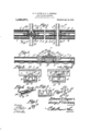
- Figure 1 is a plan view of a portion of a tie, parts being broken away, there being rails in position on the tie.
- Fig. 2 is an enlarged vertical longitudinal section through one end portion of the tie.
- Fig. 3 is an enlarged section on line A-B Fig. 1.
- Fig. 41- is a section on line CD Fig. 1.
- Fig. 5 is a section on line E-F Fig. 1.
- Fig. 6 is a perspective view of one of the rail fastening members.
- Fig. 7 is a section on line Gr-H Fig. 6.
- Fig. 8 is aperspective view of one of the rail fastening bolts and the parts cooperating therewith.
- FIG. 1 designates the top plate of the tie, the same having pockets 2 pressed downwardly thereinto at distances apart substantially equal to the distance between the rails X.
- Parallel channels 3 are pressed into the top plate 1 between the pockets 2 and additional parallel channels 4 are pressed into the top plate between the pockets 2 and the ends of the t-ie.
- Longitudinal ribs are thus formed along the side edges of the top plate, as indicated at 5, theseribs being depressed at the sides of the pockets 2, as shown at 6, the length of each depression being slightly greater than the width of a railkbase.
- a central rib 6 is formed between the channels 3 and the pockets 2 and an additional rib 7 is formed between the channels et at each end of the tie.
- the ribs6 and 7 aline and are of the same cross sectional contour.
- the side or longitudinal walls of the tie are formed integral with the top plate 1, as shown at 8 andare preferably straight from end to end, the lower portions of the said walls being folded inwardly against the bottom portions of the channels 3 and t so as to form the bottom 9 of the tie.
- These inwardly folded portions lap, as clearly shown in Figs. 3, 41 and 5, and are corrugated transversely, the inner or uppermost portions of the corrugations contacting with the bottoms of the channels 3 and 11 and vof the pockets 2 and thus constituting yielding seats therefor.
- the ends of the top plate 1 are folded downwardly to form end walls 10 the bottom portions of which are bent inwardly under the lapping parts of the bottom 9, as shown at 11.
- each of the pockets 2 is adapted to receive a cushion block 12 of wood or the like, said block having a metal cap 13 upon its upper face and on which the rail X is adapted to bear.
- a slot 1% is formed within each end portion of the rib 6 and has notches 15 in the side walls thereof. Similar slots 16 are formed within the rib 7 close to the pockets 2 and have notches 17 in their side walls. Each slot Hand 16 is adapted to receive a transversely bowed tongue 18 formed at one end of a rail fastening plate 19.
- the plate is adapted to engage a rail X and said plate has a longitudinal slot 2O for the reception of the shank 21 of a fastening bolt the head 22 of which is preferably oblong and is of such size as to be easily inserted into one of the slots 11 and 16 after which, by giving the bolt a one quarter turn, the ends, of the head can be brought into position under the walls of the slot and thus prevent withdrawal of the bolt from the tie.
- the head 22 has angular shoulders 23 upon that face thereof from which the shank 21 extends and these shoulders cooperate to form projections adapted to be seated within opposed notches 15 or 17 when the bolt is adjusted so as to bring the head 22 into contact with the notched walls of the slot 14 or 16.
- Notches 24 are formed in the shank of the bolt close to the projections 23 and are adapted to receive a U-shaped clip 25 which, when in engagement with the shank 21, prevents the bolt from dropping down into the tie.
- two kinds of plates 19 can be used.
- One of these plates has an upstanding head 2G adapted to bear against the web of a rail while the other plate has a fork 27 at one end adapted, when the plate is in position on the base iiange of the rail, to straddle one of the nuts employed for fastening aV fish plate to the rail.
- Forked plates 19 are to be used wherever two rails come together upon a tie but at other points along the track, plates such as shown in Fig. 2 are to be used.
- a metallic railway tie having transverse corrugations in the bottom thereof and longitudinal corrugations in the top thereof and bearing downwardly upon the transverse corrugations.
- a metallic railway tie having up er and lower corrugations extending in di e1'- ent directions respectively and contacting within the tie.
- a metallic railway tie having upper and lower corrugations extending in diiferent directions respectively and contacting within the tie, there being cushion receiving pockets in the top of the tie and bearing downwardly upon certain of the corrugations.
- a metallic railway tie having transverse corrugations in the bottom thereof and longitudinal corrugations in the top of the tie and bearing downwardly upon the transverse corrugations, there being pockets within the top of the tie, the sides of the tie being depressed at the sides of the pockets.
- a metallic railway tie having transverse corrugations in the bottom thereof and longitudinal corrugations in the top of the tie and bearing downwardly upon the transverse corrugations, there being pockets within the top of the tie, the sides of the tie being depressed at the sides of the pockets, cushioning blocks within the pockets, and protecting caps upon said blocks.
- G. lA metallic railway tie having transverse corrugations in the bottom thereof, and longitudinal channels in its top, the bottoms of said channels bearing within the tie upon the corrugations, there being longitudinal ribs between the channels, said ribs being slotted, and means engaging the slotted portions of the ribs for securing rails upon the tie.
- a metallic railway tie having transverse corrugations in the bottom thereof and longitudinal channels in its top bearing as our own, We have lie'eto affixed our signatures in the presence of t-Wo Witnesses.
Landscapes
- Engineering & Computer Science (AREA)
- Architecture (AREA)
- Civil Engineering (AREA)
- Structural Engineering (AREA)
- Road Paving Structures (AREA)
Description
,Eg T. PAYNE a; G. RCOGHRAN..
RAIL TIE AND FASTENER. l APPLICATION FILED NOV, 4, 19.11. I.
1,023,871; Patented A111223, 4191.2.
Z -N f7 .cf/ff jv l l 'lllllllllll/lllllzll Wit-messes v v lnventor by M Attorneys Z//M/ffag//fa UNITED STATES PATENT OFFICE.
EDWARD T. PAYNE AND GEORGE F. COCHRAN, OF ALBUQUERQUE, NEW MEXICO.
RAIL TIE`AND FASTENER.
Specification of Letters Patent.
Application filed November 4, 1911.
Patented Apr. 23, 1912.
Serial No. 658,566.
To all whom t may concern Be it known that we, EDWARD T. PAYNE and GEORGE F. COCHRAN, citizens of the United States, residing at Albuquerque, in the county of Bernalillo, State of New Mexico, have invented a new and useful Rail Tie and Fastener, of which the following is a specification.
This invention relates to metallic railway ties and to rail fasteners for use in connection therewith, the device being, more particularly, an improvement upon the structure disclosed in Patent Number 917,118, issued to us on April 6, 1909.
One of the objects of this invention is to provide an all metal tie desirable for use upon all kinds of railway road beds, the construction of the tie being such as to yieldingly support the rails.
Another object is to provide a metallic railway tie adapted to be stamped from sheet metal and having a novel arrangement of corrugations therein whereby the tie is reinforced throughout its length, one set of corrugations constituting means for preventing the tie from becoming displaced laterally relative to the rails.
A further object is to provide improved means, cooperating with the tie, for securing rails in place, said means being so constructed and mounted as to hold the rails positively in position even though the securing bolts should become broken.
With the foregoing and other objects in view which will appear as the description proceeds, the invention resides in the combination and arrangement'of parts and in the details of construct-ion hereinafter described and claimed, it being understood that changes in the precise embodiment of the invention herein disclosed can be made within the scope of what is claimed, without departing from the spirit of the invention.
In the accompanying drawings, the preferred form of the invention has been shown.
In said drawings Figure 1 is a plan view of a portion of a tie, parts being broken away, there being rails in position on the tie. Fig. 2 is an enlarged vertical longitudinal section through one end portion of the tie. Fig. 3 is an enlarged section on line A-B Fig. 1. Fig. 41- is a section on line CD Fig. 1. Fig. 5 is a section on line E-F Fig. 1. Fig. 6 is a perspective view of one of the rail fastening members. Fig. 7 is a section on line Gr-H Fig. 6. Fig. 8 is aperspective view of one of the rail fastening bolts and the parts cooperating therewith.
Referring to the figures by characters of reference 1 designates the top plate of the tie, the same having pockets 2 pressed downwardly thereinto at distances apart substantially equal to the distance between the rails X. Parallel channels 3 are pressed into the top plate 1 between the pockets 2 and additional parallel channels 4 are pressed into the top plate between the pockets 2 and the ends of the t-ie. Longitudinal ribs are thus formed along the side edges of the top plate, as indicated at 5, theseribs being depressed at the sides of the pockets 2, as shown at 6, the length of each depression being slightly greater than the width of a railkbase. A central rib 6 is formed between the channels 3 and the pockets 2 and an additional rib 7 is formed between the channels et at each end of the tie. The ribs6 and 7 aline and are of the same cross sectional contour.
The side or longitudinal walls of the tie are formed integral with the top plate 1, as shown at 8 andare preferably straight from end to end, the lower portions of the said walls being folded inwardly against the bottom portions of the channels 3 and t so as to form the bottom 9 of the tie. These inwardly folded portions lap, as clearly shown in Figs. 3, 41 and 5, and are corrugated transversely, the inner or uppermost portions of the corrugations contacting with the bottoms of the channels 3 and 11 and vof the pockets 2 and thus constituting yielding seats therefor. The ends of the top plate 1 are folded downwardly to form end walls 10 the bottom portions of which are bent inwardly under the lapping parts of the bottom 9, as shown at 11. By forming the tiewith transverse corrugations it will be apparent that after the tie has once been placed on a road bed, the corrugations will prevent it from creeping longitudinally. Moreover as the corrugations constitute supports for the longitudinally extending channel walls, it will be apparent that the tie can be made of comparatively thin metal, thus providing the necessary elasticity without reducing the eiiiciency of the device. Each of the pockets 2 is adapted to receive a cushion block 12 of wood or the like, said block having a metal cap 13 upon its upper face and on which the rail X is adapted to bear.
A slot 1% is formed within each end portion of the rib 6 and has notches 15 in the side walls thereof. Similar slots 16 are formed within the rib 7 close to the pockets 2 and have notches 17 in their side walls. Each slot Hand 16 is adapted to receive a transversely bowed tongue 18 formed at one end of a rail fastening plate 19. rlhe other end of the plate isadapted to engage a rail X and said plate has a longitudinal slot 2O for the reception of the shank 21 of a fastening bolt the head 22 of which is preferably oblong and is of such size as to be easily inserted into one of the slots 11 and 16 after which, by giving the bolt a one quarter turn, the ends, of the head can be brought into position under the walls of the slot and thus prevent withdrawal of the bolt from the tie. The head 22 has angular shoulders 23 upon that face thereof from which the shank 21 extends and these shoulders cooperate to form projections adapted to be seated within opposed notches 15 or 17 when the bolt is adjusted so as to bring the head 22 into contact with the notched walls of the slot 14 or 16. lVith the projections 23 thus seated in the notches, it will be apparent that the bolt will be held against rotation. Notches 24: are formed in the shank of the bolt close to the projections 23 and are adapted to receive a U-shaped clip 25 which, when in engagement with the shank 21, prevents the bolt from dropping down into the tie.
, As shown particularly in Fig. 1, two kinds of plates 19 can be used. One of these plates has an upstanding head 2G adapted to bear against the web of a rail while the other plate has a fork 27 at one end adapted, when the plate is in position on the base iiange of the rail, to straddle one of the nuts employed for fastening aV fish plate to the rail. Forked plates 19 are to be used wherever two rails come together upon a tie but at other points along the track, plates such as shown in Fig. 2 are to be used. After the tie has been placed in position with the cushion blocks 12 therein and the rails resting on the blocks, bolts are inserted head first into the slots 14 and 1G and the heads are each given a one-quarter turn so as to bring the angular projections 23 into register with opposed notches. The bolts are then drawn upwardly until stopped by the heads coming into contact with the walls of the slots, this movement bringing the projections 23 into the notches. The U-shaped clips 25 are then placed in engagement with the shanks 21, thus supporting the bolts in proper position. After the bolts have thus been positioned, the tongues 1S of the plates 19 are inserted into the slots so as to engage the walls of opposed notches, it being understood that the Shanks 21 of the bolts extend through the slots 20. The plates 19 are to be adjusted so as to it snugly against the rails after which by tightening nuts upon the shanks 21, the parts will be held securely together.
It will be apparent that the rail fastening means herein described can be easily adjusted so as to hold rails at any desired distances apart and, should any one of the bolts become broken, the fastening plates 19 will prevent the rails from spreading because the tongues 1S continue to engage the notched walls of the slots.
that is claimed is z 1. A metallic railway tie having transverse corrugations in the bottom thereof and longitudinal corrugations in the top thereof and bearing downwardly upon the transverse corrugations.
2. A metallic railway tie having up er and lower corrugations extending in di e1'- ent directions respectively and contacting within the tie.
3. A metallic railway tie having upper and lower corrugations extending in diiferent directions respectively and contacting within the tie, there being cushion receiving pockets in the top of the tie and bearing downwardly upon certain of the corrugations.
11. A metallic railway tie having transverse corrugations in the bottom thereof and longitudinal corrugations in the top of the tie and bearing downwardly upon the transverse corrugations, there being pockets within the top of the tie, the sides of the tie being depressed at the sides of the pockets.
5. A metallic railway tie having transverse corrugations in the bottom thereof and longitudinal corrugations in the top of the tie and bearing downwardly upon the transverse corrugations, there being pockets within the top of the tie, the sides of the tie being depressed at the sides of the pockets, cushioning blocks within the pockets, and protecting caps upon said blocks.
G. lA metallic railway tie having transverse corrugations in the bottom thereof, and longitudinal channels in its top, the bottoms of said channels bearing within the tie upon the corrugations, there being longitudinal ribs between the channels, said ribs being slotted, and means engaging the slotted portions of the ribs for securing rails upon the tie.
7. A metallic railway tie having transverse corrugations in the bottom thereof and longitudinal channels in its top bearing as our own, We have lie'eto affixed our signatures in the presence of t-Wo Witnesses.
EDWARD T. PAYNE. GEORGE F. COCHRAN.
within the tie upon the coriugations, there being longitudinally slotted ribs between the Channels, and means adjustably engaging the slotted portions of the ribs for securing 5 rails upon the tie, said means including nut Witnesses:
holding portions. FRANK Woon, In testimony that We claim the foregoing T. J. BRYANT.
Copies of this patent may be obtained for ve cents each, by addressing the Commissioner of Patents, Washington, D. C.
Priority Applications (1)
| Application Number | Priority Date | Filing Date | Title |
|---|---|---|---|
| US65856611A US1023871A (en) | 1911-11-04 | 1911-11-04 | Rail tie and fastener. |
Applications Claiming Priority (1)
| Application Number | Priority Date | Filing Date | Title |
|---|---|---|---|
| US65856611A US1023871A (en) | 1911-11-04 | 1911-11-04 | Rail tie and fastener. |
Publications (1)
| Publication Number | Publication Date |
|---|---|
| US1023871A true US1023871A (en) | 1912-04-23 |
Family
ID=3092167
Family Applications (1)
| Application Number | Title | Priority Date | Filing Date |
|---|---|---|---|
| US65856611A Expired - Lifetime US1023871A (en) | 1911-11-04 | 1911-11-04 | Rail tie and fastener. |
Country Status (1)
| Country | Link |
|---|---|
| US (1) | US1023871A (en) |
Cited By (3)
| Publication number | Priority date | Publication date | Assignee | Title |
|---|---|---|---|---|
| US2546046A (en) * | 1947-04-25 | 1951-03-20 | Richard T Scholes | Anticreeping device for rail way rails |
| US2600089A (en) * | 1946-10-29 | 1952-06-10 | Arthur | Rail anchor |
| US2628035A (en) * | 1948-06-14 | 1953-02-10 | James M Fawcett | Railway rail fastener |
-
1911
- 1911-11-04 US US65856611A patent/US1023871A/en not_active Expired - Lifetime
Cited By (3)
| Publication number | Priority date | Publication date | Assignee | Title |
|---|---|---|---|---|
| US2600089A (en) * | 1946-10-29 | 1952-06-10 | Arthur | Rail anchor |
| US2546046A (en) * | 1947-04-25 | 1951-03-20 | Richard T Scholes | Anticreeping device for rail way rails |
| US2628035A (en) * | 1948-06-14 | 1953-02-10 | James M Fawcett | Railway rail fastener |
Similar Documents
| Publication | Publication Date | Title |
|---|---|---|
| US1249161A (en) | Rail-fastener. | |
| US971308A (en) | Railroad joint-chair. | |
| US1225503A (en) | Railroad cross-tie. | |
| US862472A (en) | Means for securing rails to railroad-ties. | |
| US1009568A (en) | Spike-holder. | |
| US256199A (en) | Railroad-tie | |
| US1055896A (en) | Tie and rail-fastener. | |
| US839698A (en) | Rail-tie and fastener. | |
| US959065A (en) | Railway-tie. | |
| US1048665A (en) | Rail-fastening. | |
| US1067127A (en) | Rail-tie and rail-fastening. | |
| US1031981A (en) | Railway-tie and fastener. | |
| US1048651A (en) | Rail-fastener. | |
| US1025704A (en) | Metallic tie and rail-fastener. | |
| US410236A (en) | Railway-tie | |
| US893941A (en) | Railway-tie and means for securing rails thereto. | |
| US922835A (en) | Rail-joint. | |
| US1089632A (en) | Railroad angle-bar. | |
| US993254A (en) | Railroad-tie and fastening. | |
| USRE12261E (en) | Reissued aug | |
| US1010589A (en) | Railway-tie and fastener. | |
| US1030157A (en) | Tie and rail-fastener. | |
| US1227811A (en) | Antricreeping means for railway-rails. | |
| US1029426A (en) | Device for securing rails to ties. | |
| US1128599A (en) | Pressed-steel-cap rail carrier and clamp for ties. |