US10227790B2 - Method for mounting internal tower fittings - Google Patents
Method for mounting internal tower fittings Download PDFInfo
- Publication number
- US10227790B2 US10227790B2 US14/915,510 US201414915510A US10227790B2 US 10227790 B2 US10227790 B2 US 10227790B2 US 201414915510 A US201414915510 A US 201414915510A US 10227790 B2 US10227790 B2 US 10227790B2
- Authority
- US
- United States
- Prior art keywords
- supply module
- tower
- separate supply
- wind turbine
- turbine tower
- Prior art date
- Legal status (The legal status is an assumption and is not a legal conclusion. Google has not performed a legal analysis and makes no representation as to the accuracy of the status listed.)
- Active
Links
Images




Classifications
-
- E—FIXED CONSTRUCTIONS
- E04—BUILDING
- E04H—BUILDINGS OR LIKE STRUCTURES FOR PARTICULAR PURPOSES; SWIMMING OR SPLASH BATHS OR POOLS; MASTS; FENCING; TENTS OR CANOPIES, IN GENERAL
- E04H12/00—Towers; Masts or poles; Chimney stacks; Water-towers; Methods of erecting such structures
- E04H12/34—Arrangements for erecting or lowering towers, masts, poles, chimney stacks, or the like
-
- E—FIXED CONSTRUCTIONS
- E04—BUILDING
- E04H—BUILDINGS OR LIKE STRUCTURES FOR PARTICULAR PURPOSES; SWIMMING OR SPLASH BATHS OR POOLS; MASTS; FENCING; TENTS OR CANOPIES, IN GENERAL
- E04H12/00—Towers; Masts or poles; Chimney stacks; Water-towers; Methods of erecting such structures
- E04H12/02—Structures made of specified materials
- E04H12/08—Structures made of specified materials of metal
-
- E—FIXED CONSTRUCTIONS
- E04—BUILDING
- E04H—BUILDINGS OR LIKE STRUCTURES FOR PARTICULAR PURPOSES; SWIMMING OR SPLASH BATHS OR POOLS; MASTS; FENCING; TENTS OR CANOPIES, IN GENERAL
- E04H12/00—Towers; Masts or poles; Chimney stacks; Water-towers; Methods of erecting such structures
- E04H12/02—Structures made of specified materials
- E04H12/12—Structures made of specified materials of concrete or other stone-like material, with or without internal or external reinforcements, e.g. with metal coverings, with permanent form elements
-
- F—MECHANICAL ENGINEERING; LIGHTING; HEATING; WEAPONS; BLASTING
- F03—MACHINES OR ENGINES FOR LIQUIDS; WIND, SPRING, OR WEIGHT MOTORS; PRODUCING MECHANICAL POWER OR A REACTIVE PROPULSIVE THRUST, NOT OTHERWISE PROVIDED FOR
- F03D—WIND MOTORS
- F03D13/00—Assembly, mounting or commissioning of wind motors; Arrangements specially adapted for transporting wind motor components
- F03D13/10—Assembly of wind motors; Arrangements for erecting wind motors
-
- F—MECHANICAL ENGINEERING; LIGHTING; HEATING; WEAPONS; BLASTING
- F03—MACHINES OR ENGINES FOR LIQUIDS; WIND, SPRING, OR WEIGHT MOTORS; PRODUCING MECHANICAL POWER OR A REACTIVE PROPULSIVE THRUST, NOT OTHERWISE PROVIDED FOR
- F03D—WIND MOTORS
- F03D80/00—Details, components or accessories not provided for in groups F03D1/00 - F03D17/00
- F03D80/80—Arrangement of components within nacelles or towers
-
- Y—GENERAL TAGGING OF NEW TECHNOLOGICAL DEVELOPMENTS; GENERAL TAGGING OF CROSS-SECTIONAL TECHNOLOGIES SPANNING OVER SEVERAL SECTIONS OF THE IPC; TECHNICAL SUBJECTS COVERED BY FORMER USPC CROSS-REFERENCE ART COLLECTIONS [XRACs] AND DIGESTS
- Y02—TECHNOLOGIES OR APPLICATIONS FOR MITIGATION OR ADAPTATION AGAINST CLIMATE CHANGE
- Y02E—REDUCTION OF GREENHOUSE GAS [GHG] EMISSIONS, RELATED TO ENERGY GENERATION, TRANSMISSION OR DISTRIBUTION
- Y02E10/00—Energy generation through renewable energy sources
- Y02E10/70—Wind energy
- Y02E10/72—Wind turbines with rotation axis in wind direction
-
- Y—GENERAL TAGGING OF NEW TECHNOLOGICAL DEVELOPMENTS; GENERAL TAGGING OF CROSS-SECTIONAL TECHNOLOGIES SPANNING OVER SEVERAL SECTIONS OF THE IPC; TECHNICAL SUBJECTS COVERED BY FORMER USPC CROSS-REFERENCE ART COLLECTIONS [XRACs] AND DIGESTS
- Y02—TECHNOLOGIES OR APPLICATIONS FOR MITIGATION OR ADAPTATION AGAINST CLIMATE CHANGE
- Y02E—REDUCTION OF GREENHOUSE GAS [GHG] EMISSIONS, RELATED TO ENERGY GENERATION, TRANSMISSION OR DISTRIBUTION
- Y02E10/00—Energy generation through renewable energy sources
- Y02E10/70—Wind energy
- Y02E10/728—Onshore wind turbines
Definitions
- the invention relates to a method for installing tower fittings by introducing at least two separate supply modules into a wind turbine tower, wherein a separate supply module structurally comprises one segment each of at least two system components of the wind turbine tower, and wherein an upper segment end is arranged on an upper edge, and a lower segment end on a lower edge, of the supply module.
- Powerful wind turbines require large rotors and high wind speeds. High wind speeds are found far above the ground.
- the towers of the wind turbines therefore have a very high construction.
- high wind turbine towers permit larger rotors.
- the towers require a sufficiently high degree of stability in order to act as a support structure for the large and therefore also heavy rotors.
- Said towers are constructed locally at the construction site of the wind turbine since said towers are much too large for premanufacturing. It has proven successful to erect the towers from a plurality of concrete tower segments arranged one above another. The tower segments here can be completely or partially produced from semi-finished elements. High towers can thereby be efficiently erected even in remote areas.
- the tower fittings which comprise, for example, conduction means for transmitting the electrical energy generated in the nacelle or for transmitting control signals for operating the wind turbine, or a climbing device for the operating personnel for climbing up the tower.
- the installation of the tower fittings in the erected tower is complicated and hazardous since work at a great height is partly also required.
- DE 10 2010 015 075 A1 discloses segmenting at least two system components of the tower fittings and structurally combining said segments to form separate supply modules.
- the supply modules are preassembled at the construction site or ex works and, for installation, are introduced into the tower interior.
- a supply module is fastened here to the tower inner wall at the designated location.
- the segments of the system components of supply modules adjacent to one another are coupled to one another, for example via series connection devices. Manufacturing-induced tolerances in the tower segments are compensated for here either during the connection of supply modules adjacent to one another or at the supply module which is fastened at the upper end of the wind turbine tower.
- An object on which the invention is based is the provision of a method which further simplifies the installation of the tower fittings and increases the safety of the installation personnel during the installation of the tower fittings.
- a separate supply module structurally comprises one segment each of at least two system components of the wind turbine tower, and wherein an upper segment end is arranged on an upper edge, and a lower segment end on a lower edge, of the supply module
- a system component is understood as meaning components of the wind turbine that are installed in the tower of the wind turbine in order to enable the maintenance and operation thereof.
- Said components can be, for example, power conduction means, signal conduction means, illuminating means or a climbing device for operating personnel.
- An upper edge is understood as meaning that edge of a supply module which, in the fitted position, is aligned with the nacelle of the wind turbine.
- a lower edge is understood as meaning that edge of the supply module which is directed toward the tower base.
- An upper end of the wind turbine tower is understood as meaning a region at the upper end of the tower. Said region does not necessarily have to be arranged directly at the highest point of the wind turbine tower. It may also be arranged a few meters below the highest point. In the case of towers composed of a different material in sections, for example a concrete tower at the bottom and a tubular steel tower placed on at the top, each upper end of a portion is an “upper end” within the meaning of the invention.
- the invention is based on the finding that the separate supply modules can be connected to one another as they are being introduced into the wind turbine tower, before said supply modules are fastened, optionally in their entirety, to the tower inner wall.
- the supply modules are inserted from above, that is to say said supply modules are guided past the upper end of the wind turbine tower.
- the upper edge of the first separate supply module introduced first is arranged there on the lower edge of the second separate supply module to be introduced next.
- the segments of the system components of the two separate supply modules are connected to each other via the segment ends arranged on the edges.
- the separate supply modules which are now connected to each other are then lowered downward until the upper edge of the second supply module is arranged at the upper end of the wind turbine tower.
- the operation is repeated until all of the supply modules which are to be installed have been introduced into the tower interior.
- the separate supply modules which are connected to each other are finally then fastened to the inner wall of the wind turbine tower after the final separate supply module has been arranged at the upper end of the wind turbine tower and the completely assembled supply module has been brought into the final installation position.
- the supply modules are therefore connected successively to one another and lowered into the tower.
- the connecting work for joining together the supply modules can therefore be carried out at a central, stationary work site.
- the installation personnel no longer needs to handle the connecting points between the supply modules along the tower inner wall, but instead the supply modules which are to be installed migrate, as it were, past the stationary work site.
- a stationary working platform for the installation personnel is customarily provided in any case at the upper end of the wind turbine tower, no additional outlay is required.
- said working platform provides greater safety than mobile working devices which would have to be arranged in a vertically movable manner on the tower inner wall.
- connection of the segments of the system components to the upper end of the wind turbine tower are always arranged in a defined position relative to the tip of the tower.
- the position of the lower end of the supply modules which are connected to one another is no longer of importance. Compensating work needs only to be carried out—if at all—at the tower base. Since the work is not carried out there at a great height, the safety of the installation personnel should be ensured in a simple manner. It is now no longer necessary to carry out compensating work on the basis of the tower tolerances at each connecting point between the separate supply modules. This considerably simplifies the installation of the tower fittings.
- the fastening to the tower inner wall in particular prevents the supply module from being displaced in a horizontal plane.
- the main load in terms of weight of the supply module continues to be supported by the suspension at the upper tower end.
- the holding apparatus advantageously comprises at least one connecting device for the connection to a separate supply module.
- the holding apparatus expediently has at least one load ring which is fastened to the tower wall or tower upper edge, wherein the connecting device comprises at least one shackle or a lifting sling.
- the first separate supply module can advantageously therefore be suspended at the upper end of the wind turbine tower before the segments of the system components are connected to those of the second separate supply module.
- the suspended supply module is secured by the holding device at the upper end of the wind turbine tower, and therefore the connection of the system component segments to a supply module arranged above the suspended supply module is further simplified.
- the design of the holding device comprising a load ring and a shackle or a lifting sling, permits a simple connection of the upper edge of the suspended supply module to the holding apparatus.
- the supply module can have a support plate to which the connecting devices are fastened.
- the latter can be fastened to the tower wall or tower upper edge by means of the load ring.
- the support plate can be designed as an angled support plate for fastening the final separate supply module to the tower wall or tower upper edge.
- the final separate supply module can be hung over the tower upper edge and fastened to the tower wall or tower upper edge. The fastening outlay for the final separate supply module to the tower wall or tower upper edge is therefore reduced.
- the holding apparatus can furthermore advantageously comprise at least one support element which is fastened to the tower wall or to the tower upper edge and to which a support module comprising a mounting portion is releasably fastened, wherein the supply module has a mounting element with which the separate supply module, after the arrangement of the upper edge at an upper end of the wind turbine tower, is mounted on the mounting portion of the support module.
- the support module has a mounting portion in which the mounting element can be arranged.
- the mounting element is supported by the mounting portion.
- the support module can be fastened to the tower upper edge even without the use of a support element.
- the supply modules do not require any fastening to the holding apparatus by means of the shackles.
- the shackles can optionally be used for fastening the separate supply modules after the final separate supply module has been introduced into the tower interior.
- the wind turbine tower is advantageously formed from at least two tower segments. Furthermore, it is expedient that the separate supply modules span a plurality of tower segments. A smaller number of separate supply modules than the number of tower segments is therefore required for fitting into the tower interior. This reduces the amount of required connecting work between the supply modules, and further simplifies and accelerates the installation of the tower fittings. To reduce the diversity of variants of the separate supply modules, it is expedient to design both the lowermost supply module in each case and the supply modules in each case lying in between to be identical. A rough adaptation to the respective tower height is achieved via the number of supply modules lying in between and to be mounted. The precise coordination with the ultimately required length of the complete supply module is achieved by adaptation of the uppermost separate supply module.
- the system components expediently comprise power conduction means, signal conduction means, illuminating means and/or a climbing device for operating personnel, wherein the illuminating means comprise lamps arranged discretely or continuously.
- a tubular steel tower can advantageously be installed as an upper part of the wind turbine tower, wherein the lower part is a concrete tower.
- the supply modules are advantageously introduced into the concrete tower prior to the placing-on of a tubular steel tower.
- the system components can be installed in the tubular steel tower ex works, on the construction site or after the tubular steel tower has been erected. By fitting the supply modules as per the method according to the invention before the tubular steel tower is erected, it is ensured that the upper edge of the supply module fitted last in the concrete tower bears against a defined point relative to the upper end of the wind turbine tower.
- the coupling between the system components installed in the tubular steel tower and the system components of the concrete tower can therefore take place without special compensating work.
- a support plate, which is of angled design, of a supply module introduced last can be connected to the tubular steel tower in order to prevent the support plate from slipping off a tower upper edge of a concrete tower.
- fastening apparatus prior to the introduction of the separate supply modules into the wind turbine tower, to fasten at least one fastening apparatus to at least one of the separate supply modules, said fastening apparatus having a clamping element which is connected to the supply module and a guide element, comprising a fastening piece projecting laterally on the supply module, which is arranged between the clamping element and the supply module. Projecting laterally on the supply module is understood as meaning that, when a supply module hangs on the tower inner wall, the fastening piece runs along the wall and the supply module does not cover the fastening piece.
- the fastening apparatuses can therefore be introduced together with the supply modules into the tower interior, which further simplifies the fitting of the separate supply modules.
- the guide element is movable here in a vertical direction along the separate supply module, and therefore the guide element can be arranged flexibly along the separate supply module.
- the fastening pieces can be reached directly from the front because of the lateral projection thereof from the supply modules.
- the installation personnel can therefore easily reach the fastening pieces and in an uncomplicated manner carry out the fastening of the supply modules introduced into the tower interior.
- the supply modules are secured in the horizontal direction.
- a vertical displacement for aligning the supply modules is furthermore permitted until the guide element of the fastening apparatus is clamped by means of the clamping element.
- the guide element is clamped between the clamping element and the separate supply module.
- the clamping can be brought about by fastening elements which press the clamping element onto the supply module.
- the fastening elements can be actuated here from the front side of the supply module.
- the supply module therefore cannot be moved further along the guide element.
- the invention furthermore relates to a wind turbine tower, comprising a holding device for the suspension of a separate supply module at the upper end of a wind turbine tower for carrying out the abovementioned method.
- a wind turbine tower comprising a holding device for the suspension of a separate supply module at the upper end of a wind turbine tower for carrying out the abovementioned method.
- FIG. 1 shows a schematic illustration of a wind turbine with tower fittings
- FIGS. 2 a - d show a schematic illustration of individual method steps
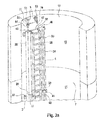
- FIGS. 3 a, b show a schematic illustration of the supply modules suspended in the tower interior on a holding apparatus, with (a) shackles and (b) lifting slings;
- FIG. 4 shows a schematic illustration of a hybrid tower
- FIGS. 5 a, b show a schematic illustration of a supply module, a support module and a support element in the separate state (a) and mounted state (b);
- FIG. 6 shows a schematic illustration of a fastening apparatus arranged on a supply module
- FIG. 7 shows a schematic cross-sectional view of a fastening apparatus arranged on a supply module
- FIG. 8 shows a schematic illustration of the final supply module fastened to an angled support plate.
- the method is carried out for the erection of a wind turbine, denoted in the entirety thereof by the reference number 100 .
- the wind turbine 100 comprises a wind turbine tower 1 which is erected from a plurality of tower segments 10 , 11 , 12 , 13 , 14 , 15 , 16 and is designed as a hybrid tower.
- the lower part of the hybrid tower is a concrete tower 19 and the upper part is a tubular steel tower 18 .
- the wind turbine 100 comprises a nacelle 101 , which is connected to an upper end 17 of the wind turbine tower 1 , and a rotor 102 , which is mounted rotatably on one side of the nacelle 101 .
- the rotor 102 is connected to an electric generator 104 via a shaft 103 .
- the wind turbine 100 comprises an operation controller 105 which is connected to the generator 104 and to the rotor 102 via signal lines.
- the operation controller 105 and the generator 104 are arranged in the nacelle 101 .
- the wind turbine 100 comprises a transformer 106 for connection to the electrical grid.
- the generator 104 and the transformer 106 are connected via power conduction means 33 for transmitting the power generated by the generator 104 to the grid.
- a climbing device 36 which includes illuminating means 35 , for operating personnel is fastened in the interior of the wind turbine tower 1 to the tower inner wall, wherein the illuminating means comprise lamps arranged discretely or continuously.
- signal conduction means 34 are provided in the tower interior.
- the power conduction means 33 , signal conduction means 34 , illuminating means 35 and the climbing device 36 for operating personnel are referred to in summary as system components 33 , 34 , 35 , 36 .
- the system components 33 , 34 , 35 , 36 are divided in each case into individual segments.
- the segments of at least two different system components 33 , 34 , 35 , 36 are structurally combined to form a separate supply module 3 , 4 .
- the structural combining simplifies the fitting of the supply modules 3 , 4 after the wind turbine tower 1 has been erected.
- the supply modules 3 , 4 each have an upper edge 37 , 47 and a lower edge 38 , 48 .
- the upper segment end 30 , 40 of the system components 33 , 34 , 35 , 36 is arranged on the upper edge 37 , 47 .
- the lower segment end 31 , 41 of the system components 33 , 34 , 35 , 36 is arranged on the lower edge 38 , 48 of the separate supply module 3 , 4 .
- the separate supply modules 3 , 4 can be preassembled at the works.
- the separate supply modules 3 , 4 can be assembled at the construction site. The preassembly of the supply modules can take place in the horizontal position.
- the wind turbine tower 1 is erected from the tower segments 10 to 16 .
- a working platform 6 is installed at the upper end 17 of the wind turbine tower 1 after erection.
- the working platform 6 is used for the installation personnel to be on during the erection and installation work on the wind turbine tower 1 .
- the working platform can be used for subsequent maintenance work, in particular at the transition piece to the hybrid tower.
- the working platform 6 can have rails and eyes for safety ropes.
- the working platform 6 can extend over the entire tower inside diameter and can have a suitable cutout for the system components.
- the separate supply modules are then guided downward through the cutout in the working platform 6 .
- Individual supply modules can be provided with additional components (for example feed boxes), as a result of which the cross section of the supply modules is increased.
- the working platform 6 can be equipped with a floor flap, as a result of which the cutout in the working platform can be temporarily enlarged for the passage of said additional components.
- a holding device 5 is fastened to the upper end 17 of the wind turbine tower 1 .
- the holding device 5 comprises two connecting devices 51 , 52 for the connection to a separate supply module 3 , 4 .
- a connecting device 51 , 52 is formed from two shackles, which are coupled to each other and are fastened to a load ring 53 , which is fastened to the tower wall.
- a supply module 3 , 4 can be suspended on the shackles by means of a support plate 54 which has eyes 39 for this purpose.
- the holding device 5 is designed here in such a manner that it can be loaded with the entire weight of all of the separate supply modules 3 , 4 to be fitted.
- the support plate 54 can also be designed as an elbow and, for the temporary suspension of a separate supply module 3 , 4 , can be hung directly over the tower upper edge.
- the support plate 54 is then fastened to the tower upper edge, for example by means of bolts.
- precision bolts may be provided as security against slipping off.
- a support element 55 on which a support module 8 can be mounted, is provided on the holding apparatus 5 .
- the support module 8 has a resting portion 82 which is formed in a complementary manner with respect to the support element 55 and is bordered by a flange 83 .
- the resting portion 82 is arranged on the support element 55 .
- the support module 8 is secured against displacement from the support element 55 by means of the flange 83 .
- the support module 8 furthermore has a mounting portion 81 .
- a mounting element 49 fastened to the separate supply module 3 , 4 can be arranged in the mounting portion 81 .
- the support module 8 can be fastened to the tower upper edge even without the use of a support element 55 .
- the suspension of the supply modules 3 , 4 on the support module 8 can be further simplified.
- the final separate supply module 4 introduced into the wind turbine tower 1 can be fastened to the shackles or to the tower upper edge directly via an angled support plate 54 .
- a fastening apparatus 9 is provided for the final fastening of the separate supply modules 3 , 4 to the tower inner wall 7 .
- the fastening apparatus 9 comprises a clamping element 92 which is fastened to the support module 3 , 4 by means of fastening elements 93 .
- the fastening elements 93 are reachable from the front side of the separate supply modules 3 , 4 and can be actuated from there.
- a guide element 94 is provided between the clamping element 92 and the supply module 3 , 4 .
- the guide element 94 furthermore has spacers 95 , 96 and a fastening piece 91 .
- the fastening piece 91 projects laterally from the supply module. It can easily be reached by the installation personnel for connection to the tower wall.
- the spacer 96 spaces the separate supply module 3 , 4 and the wall.
- the spacer 95 furthermore acts as a resting element and guide element for the clamping element 92 .
- the clamping element 92 By actuation of the fastening elements 93 , the clamping element 92 is pressed against the separate supply module 3 , 4 .
- the clamping element 92 presses here onto the guide element 94 via the spacer 95 .
- the guide element 94 is clamped between the clamping element 92 and the separate supply module 3 , 4 .
- FIG. 2 a illustrates a wind turbine tower 1 with a working platform 6 at the upper end 17 thereof, said wind turbine tower having been erected from the tower segments 10 to 16 .
- the tower segments 10 to 16 form a concrete tower 19 which, in this preferred embodiment, acts as a lower part of a hybrid tower.
- the holding device 5 is installed at the upper end of the wind turbine tower 1 .
- a support module 8 is placed onto the holding device 5 .
- a first separate supply module 3 which in the completely constructed state of the wind turbine 100 is arranged at the base of the wind turbine tower 1 , is disposed onto the upper end 17 of the wind turbine tower 1 with a crane (not illustrated).
- the guide elements 94 of the fastening apparatuses 9 fastened to the separate supply module 3 are still free here and can be moved along the supply module 3 in the vertical direction.
- the installation personnel on the working platform 6 guide the first separate supply module 3 during the subsequent lowering thereof into the interior of the wind turbine tower 1 .
- FIGS. 2 b , 2 c , 2 d , 3 a , 3 d and 8 the wall portions concealing the tower interior have been omitted in FIGS. 2 b , 2 c , 2 d , 3 a , 3 d and 8 such that the tower inner wall 7 is visible.
- the first separate supply module 3 is lowered into the tower interior until the upper edge 37 of the supply module 3 is arranged at the upper end 17 of the wind turbine tower 1 .
- the upper edge is arranged on the working platform 6 in such a manner that the installation personnel can carry out work on the upper edge 37 from the working platform.
- the first separate supply module 3 is hung onto the holding device 5 at the mounting portion 81 of the support module 8 by means of the mounting element 49 .
- the first separate supply module 3 is then released by the crane and hangs with its full weight on the holding device 5 .
- the upper segment ends 30 of the system components 33 , 34 , 35 , 36 are likewise arranged at the upper end 17 of the wind turbine tower 1 .
- the first separate supply module 3 spans a plurality of the tower segments 10 to 16 . That is to say the upper edge 37 of the first separate supply module 3 is arranged on a different tower segment 10 to 16 than the lower edge 38 of the first separate supply module 3 .
- the second separate supply module 4 is raised with the crane and arranged with its lower edge 48 on the upper edge 37 of the first separate supply module 3 .
- the lower segment ends 41 of the system components 33 , 34 , 35 , 36 of the second separate supply module 4 are aligned with the upper segment ends 30 of the system components 33 , 34 , 35 , 36 of the first separate supply module 3 .
- the upper segment ends 30 are connected to the lower segment ends 41 by the installation personnel. The installation personnel can carry this out from the working platform 6 .
- the first separate supply module 3 and the second separate supply module 4 are connected to each other.
- the holding device 5 is released from the first separate supply module 3 .
- the supply module 3 is unhooked from the support module 8 .
- the separate supply modules 3 , 4 which are connected to each other are lowered further into the tower interior by the crane until the upper edge 47 of the second separate supply module 4 is arranged at the upper end of the wind turbine tower 1 .
- the second separate supply module 4 is then hung on the holding device 5 by means of the mounting element 49 , which is fastened to the separate supply module 4 , and the support module 8 , and released from the crane.
- the supply module is hung by means of lifting slings of the holding device 5 .
- the final separate supply module is fastened to the holding device 5 via the connecting devices 52 .
- the connecting devices 52 are guided through the holding eyes 39 of the support plate 54 of the final separate supply module and locked.
- the support plate of the final separate supply module is of angled design.
- the final separate supply module can be hung over the tower upper edge with the aid of the angled support plate 54 and fastened there with bolts.
- the angled support plate 54 can be fastened to a tubular steel tower 18 to be placed onto the concrete tower 19 .
- the first separate supply module 3 is arranged at the tower base and forms the lowermost separate supply module.
- the complete supply module hangs on the holding device 5 .
- the separate supply modules 3 , 4 are connected to the tower inner wall 7 by the fastening pieces 91 being fastened to the tower inner wall 7 .
- the fastening elements 93 are actuated such that the supply modules 3 , 4 can be pulled onto the tower inner wall 7 via the clamping elements 92 and the guide elements 94 .
- a tubular steel tower 18 is placed onto the concrete tower 19 .
- the system components 33 , 34 , 35 , 36 installed in the tubular steel tower 18 are connected to the upper segment ends 40 .
- the lower segment ends 31 of the first separate supply module 3 are optionally likewise connected to the system components 33 , 34 , 35 , 36 installed in the tower base.
Landscapes
- Engineering & Computer Science (AREA)
- Architecture (AREA)
- Life Sciences & Earth Sciences (AREA)
- Chemical & Material Sciences (AREA)
- Civil Engineering (AREA)
- Structural Engineering (AREA)
- Materials Engineering (AREA)
- Wood Science & Technology (AREA)
- Sustainable Development (AREA)
- Sustainable Energy (AREA)
- Combustion & Propulsion (AREA)
- Mechanical Engineering (AREA)
- General Engineering & Computer Science (AREA)
- Wind Motors (AREA)
Applications Claiming Priority (4)
| Application Number | Priority Date | Filing Date | Title |
|---|---|---|---|
| DE102013217088 | 2013-08-27 | ||
| DE102013217088.2A DE102013217088A1 (de) | 2013-08-27 | 2013-08-27 | Verfahren zur Montage von Turmeinbauten |
| DE102013217088.2 | 2013-08-27 | ||
| PCT/EP2014/067894 WO2015028400A1 (de) | 2013-08-27 | 2014-08-22 | Verfahren zur montage von turmeinbauten |
Publications (2)
| Publication Number | Publication Date |
|---|---|
| US20160215520A1 US20160215520A1 (en) | 2016-07-28 |
| US10227790B2 true US10227790B2 (en) | 2019-03-12 |
Family
ID=51417267
Family Applications (1)
| Application Number | Title | Priority Date | Filing Date |
|---|---|---|---|
| US14/915,510 Active US10227790B2 (en) | 2013-08-27 | 2014-08-22 | Method for mounting internal tower fittings |
Country Status (6)
| Country | Link |
|---|---|
| US (1) | US10227790B2 (da) |
| EP (1) | EP3042011B1 (da) |
| DE (1) | DE102013217088A1 (da) |
| DK (1) | DK3042011T3 (da) |
| ES (1) | ES2703206T3 (da) |
| WO (1) | WO2015028400A1 (da) |
Cited By (1)
| Publication number | Priority date | Publication date | Assignee | Title |
|---|---|---|---|---|
| US11905923B2 (en) | 2018-09-17 | 2024-02-20 | Wobben Properties Gmbh | Wind turbine tower segment for a wind turbine tower and method |
Families Citing this family (9)
| Publication number | Priority date | Publication date | Assignee | Title |
|---|---|---|---|---|
| WO2014075686A1 (en) * | 2012-11-15 | 2014-05-22 | Vestas Wind Systems A/S | Method and device for aligning tower sections |
| US10260284B2 (en) | 2015-08-31 | 2019-04-16 | Wind Tower Technologies, Inc. | Ladder installation for equipment tower |
| US10047725B2 (en) * | 2015-10-12 | 2018-08-14 | General Electric Company | Ladder attachment system for a wind turbine |
| US20180080218A1 (en) | 2016-09-21 | 2018-03-22 | Skyrise Global, Llc | Structure and method of making the same |
| ES2982788T3 (es) | 2017-01-10 | 2024-10-17 | Keystone Tower Systems Inc | Accesorio para torre de un aerogenerador |
| DE102017124615A1 (de) * | 2017-10-20 | 2019-04-25 | Max Bögl Wind AG | Verfahren zum Errichten eines Turms, Turmsegments, Versorgungsstruktur sowie Turm |
| CN116263061A (zh) * | 2021-12-14 | 2023-06-16 | 中核第七研究设计院有限公司 | 一种快速装配式塔架风筒 |
| US12529239B2 (en) * | 2022-10-31 | 2026-01-20 | Ge Infrastructure Technology Llc | Wind turbine tower structure with stacked tower sections |
| EP4656876A1 (de) * | 2024-05-28 | 2025-12-03 | Bettels Betonfertigteile GmbH | Im turminneren eines turms einer windenergieanlage aufwärts verlaufende ver-sorgungsstruktur und verfahren zum errichten einer solchen |
Citations (23)
| Publication number | Priority date | Publication date | Assignee | Title |
|---|---|---|---|---|
| US3053398A (en) * | 1958-12-23 | 1962-09-11 | Liebherr Hans | Rotary tower crane |
| US3768016A (en) * | 1972-06-01 | 1973-10-23 | Pittsburgh Des Moines Steel | Modular, prefabricated, integrated communications relay tower |
| US6713891B2 (en) * | 1998-12-17 | 2004-03-30 | Dan-Control Engineering A/S | Wind mill with a suspension for cables and the like, such suspension for cables and the like and a holder for such suspension |
| US20050247008A1 (en) * | 2002-06-05 | 2005-11-10 | Reiki Fujiwara | Scaffolding device for work on inner wall face of tower vessel body, and method of work on inner wall face using the scaffolding device |
| US20070045045A1 (en) * | 2005-08-31 | 2007-03-01 | Deuer Joseph F | Climb assist system |
| US7198134B2 (en) * | 2004-06-14 | 2007-04-03 | General Electric Company | Method and apparatus for assisting multiple climbers |
| US20070296220A1 (en) * | 2004-11-23 | 2007-12-27 | Vestas Wind Systems A/S | Wind Turbine, a Method for Assembling and Handling the Wind Turbine and Uses Hereof |
| US20090031668A1 (en) * | 2005-09-16 | 2009-02-05 | Gamesa Innovation And Technology, S.L. | Method of Mounting Elements Inside a Wind Generator Tower |
| DE202010007565U1 (de) | 2010-06-04 | 2010-09-02 | Zarges Aluminium Systeme Gmbh | Turm, insbesondere Windkraftanlagenturm |
| US20110061314A1 (en) | 2009-09-17 | 2011-03-17 | Muehlhaeuser Markus | Method of installing a cable in the tower of a wind power plant |
| US8011098B2 (en) * | 2008-08-19 | 2011-09-06 | Vorhies Roger W | Wind turbine erector |
| US20110252738A1 (en) * | 2002-02-06 | 2011-10-20 | Vestas Wind Systems A/S | Wind turbine tower suspension means |
| DE102010015075A1 (de) | 2010-04-15 | 2011-10-20 | Repower Systems Ag | Windenergieanlage mit modularem Turmsystem |
| DE202011106727U1 (de) | 2011-10-13 | 2011-10-27 | Kgw Schweriner Maschinen- Und Anlagenbau Gmbh | Versorgungsgerüst für einen Turm |
| DE102010048547A1 (de) | 2010-10-14 | 2012-04-19 | Kgw Schweriner Maschinen- Und Anlagenbau Gmbh | Turm, insbesondere für eine Windkraftanlage und Verfahren zur Herstellung eines Turmes |
| US20120168116A1 (en) * | 2009-03-13 | 2012-07-05 | Xemc Darwind B.V. | Method of constructing a wind turbine and bottom tower section of wind turbine |
| US8413405B2 (en) * | 2008-12-19 | 2013-04-09 | Repower Systems Se | Tower of a wind power plant |
| US8601748B2 (en) * | 2009-09-09 | 2013-12-10 | National Oilwell Varco, L.P. | Method and apparatus for wind turbine erection |
| US20140075860A1 (en) * | 2012-09-14 | 2014-03-20 | General Electric Company | Tower section and method for installing tower for wind turbine |
| US20140237932A1 (en) * | 2013-02-26 | 2014-08-28 | Envision Energy (Denmark) Aps | Tower assembly system for wind turbines and method thereof |
| US20150292263A1 (en) * | 2012-10-16 | 2015-10-15 | Max Bögl Wind AG | Supply Frame for a Tower; Tower with a Supply Frame and Method for Erecting a Supply Frame in the Interior of a Tower |
| US20150345463A1 (en) * | 2012-12-20 | 2015-12-03 | Vestas Wind Systems A/S | A wind turbine tower guide system, and a method for installing an installation unit |
| US9238923B2 (en) * | 2012-12-21 | 2016-01-19 | Acciona Windpower, S.A. | Wind turbine assembly system |
-
2013
- 2013-08-27 DE DE102013217088.2A patent/DE102013217088A1/de not_active Ceased
-
2014
- 2014-08-22 WO PCT/EP2014/067894 patent/WO2015028400A1/de not_active Ceased
- 2014-08-22 EP EP14755808.4A patent/EP3042011B1/de active Active
- 2014-08-22 DK DK14755808.4T patent/DK3042011T3/da active
- 2014-08-22 US US14/915,510 patent/US10227790B2/en active Active
- 2014-08-22 ES ES14755808T patent/ES2703206T3/es active Active
Patent Citations (27)
| Publication number | Priority date | Publication date | Assignee | Title |
|---|---|---|---|---|
| US3053398A (en) * | 1958-12-23 | 1962-09-11 | Liebherr Hans | Rotary tower crane |
| US3768016A (en) * | 1972-06-01 | 1973-10-23 | Pittsburgh Des Moines Steel | Modular, prefabricated, integrated communications relay tower |
| US6713891B2 (en) * | 1998-12-17 | 2004-03-30 | Dan-Control Engineering A/S | Wind mill with a suspension for cables and the like, such suspension for cables and the like and a holder for such suspension |
| US20110252738A1 (en) * | 2002-02-06 | 2011-10-20 | Vestas Wind Systems A/S | Wind turbine tower suspension means |
| US20050247008A1 (en) * | 2002-06-05 | 2005-11-10 | Reiki Fujiwara | Scaffolding device for work on inner wall face of tower vessel body, and method of work on inner wall face using the scaffolding device |
| US7198134B2 (en) * | 2004-06-14 | 2007-04-03 | General Electric Company | Method and apparatus for assisting multiple climbers |
| US20070296220A1 (en) * | 2004-11-23 | 2007-12-27 | Vestas Wind Systems A/S | Wind Turbine, a Method for Assembling and Handling the Wind Turbine and Uses Hereof |
| US20070045045A1 (en) * | 2005-08-31 | 2007-03-01 | Deuer Joseph F | Climb assist system |
| US8033078B2 (en) * | 2005-09-16 | 2011-10-11 | Gamesa Innovation & Technology, S.L. | Method of mounting elements inside a wind generator tower |
| US20090031668A1 (en) * | 2005-09-16 | 2009-02-05 | Gamesa Innovation And Technology, S.L. | Method of Mounting Elements Inside a Wind Generator Tower |
| US8011098B2 (en) * | 2008-08-19 | 2011-09-06 | Vorhies Roger W | Wind turbine erector |
| US8413405B2 (en) * | 2008-12-19 | 2013-04-09 | Repower Systems Se | Tower of a wind power plant |
| US20120168116A1 (en) * | 2009-03-13 | 2012-07-05 | Xemc Darwind B.V. | Method of constructing a wind turbine and bottom tower section of wind turbine |
| US8601748B2 (en) * | 2009-09-09 | 2013-12-10 | National Oilwell Varco, L.P. | Method and apparatus for wind turbine erection |
| US20110061314A1 (en) | 2009-09-17 | 2011-03-17 | Muehlhaeuser Markus | Method of installing a cable in the tower of a wind power plant |
| DE102009041982A1 (de) | 2009-09-17 | 2011-04-14 | Schuler Pressen Gmbh & Co. Kg | Verfahren zur Leitungsmontage im Turm einer Windkraftanlage |
| DE102010015075A1 (de) | 2010-04-15 | 2011-10-20 | Repower Systems Ag | Windenergieanlage mit modularem Turmsystem |
| US8935889B2 (en) * | 2010-04-15 | 2015-01-20 | Senvion Se | Wind power plant with modular tower system |
| US20130034450A1 (en) * | 2010-04-15 | 2013-02-07 | Repower Systems Se | Wind power plant with modular tower system |
| DE202010007565U1 (de) | 2010-06-04 | 2010-09-02 | Zarges Aluminium Systeme Gmbh | Turm, insbesondere Windkraftanlagenturm |
| DE102010048547A1 (de) | 2010-10-14 | 2012-04-19 | Kgw Schweriner Maschinen- Und Anlagenbau Gmbh | Turm, insbesondere für eine Windkraftanlage und Verfahren zur Herstellung eines Turmes |
| DE202011106727U1 (de) | 2011-10-13 | 2011-10-27 | Kgw Schweriner Maschinen- Und Anlagenbau Gmbh | Versorgungsgerüst für einen Turm |
| US20140075860A1 (en) * | 2012-09-14 | 2014-03-20 | General Electric Company | Tower section and method for installing tower for wind turbine |
| US20150292263A1 (en) * | 2012-10-16 | 2015-10-15 | Max Bögl Wind AG | Supply Frame for a Tower; Tower with a Supply Frame and Method for Erecting a Supply Frame in the Interior of a Tower |
| US20150345463A1 (en) * | 2012-12-20 | 2015-12-03 | Vestas Wind Systems A/S | A wind turbine tower guide system, and a method for installing an installation unit |
| US9238923B2 (en) * | 2012-12-21 | 2016-01-19 | Acciona Windpower, S.A. | Wind turbine assembly system |
| US20140237932A1 (en) * | 2013-02-26 | 2014-08-28 | Envision Energy (Denmark) Aps | Tower assembly system for wind turbines and method thereof |
Non-Patent Citations (1)
| Title |
|---|
| International Search Report and Written Opinion dated Nov. 5, 2014, directed to International Application No. PCT/EP2014/067894; 8 pages. |
Cited By (1)
| Publication number | Priority date | Publication date | Assignee | Title |
|---|---|---|---|---|
| US11905923B2 (en) | 2018-09-17 | 2024-02-20 | Wobben Properties Gmbh | Wind turbine tower segment for a wind turbine tower and method |
Also Published As
| Publication number | Publication date |
|---|---|
| WO2015028400A1 (de) | 2015-03-05 |
| US20160215520A1 (en) | 2016-07-28 |
| DK3042011T3 (da) | 2019-02-04 |
| EP3042011A1 (de) | 2016-07-13 |
| DE102013217088A1 (de) | 2015-03-05 |
| EP3042011B1 (de) | 2018-10-10 |
| ES2703206T3 (es) | 2019-03-07 |
Similar Documents
| Publication | Publication Date | Title |
|---|---|---|
| US10227790B2 (en) | Method for mounting internal tower fittings | |
| AU2009244469B2 (en) | Erection method for solar receiver and support tower | |
| CN104662290B (zh) | 用于塔的供应架、具有供应架的塔以及用于在塔的内部建造供应架的方法 | |
| AU2013261673B2 (en) | Self-climbing telescopic crane and method for mounting pre-fabricated concrete towers | |
| US9682846B2 (en) | Wind turbine tower with an elevator system | |
| US20040045226A1 (en) | Self-erecting tower and method for raising the tower | |
| US10119523B2 (en) | Method for moving wind turbine components and a transport system for moving wind turbine components | |
| US10252895B2 (en) | Solar array lifter and method | |
| US11300260B2 (en) | Elevated structure-mounted lighting system | |
| DK3014117T3 (da) | Transformerskiftesystem | |
| US20240052807A1 (en) | Installing equipment in offshore monopile foundations | |
| US10976016B2 (en) | Elevated structure-mounted lighting system | |
| CN107217993B (zh) | 塔架 | |
| CN110080949A (zh) | 风机起升安装方法及系统 | |
| CN114180467B (zh) | 一种拼装式起吊装置 | |
| CN203383993U (zh) | 风电直驱发电机运输底座 | |
| CN208364305U (zh) | 一种风电机组自提升吊装设备 | |
| CN106044564A (zh) | 盲穿安装导向结构的安装方法 | |
| JP2024543162A (ja) | 風力タービンブレード設置システム及び関連する方法 | |
| CN106115506B (zh) | 攀爬平台和攀爬装置 | |
| CA3092801C (en) | Elevated structure-mounted lighting system | |
| RU107248U1 (ru) | Мачта сборно-разборной конструкции | |
| CN106049970A (zh) | 高耸贵金属塔桅无触点吊具系统的安装方法 |
Legal Events
| Date | Code | Title | Description |
|---|---|---|---|
| AS | Assignment |
Owner name: SENVION GMBH, GERMANY Free format text: ASSIGNMENT OF ASSIGNORS INTEREST;ASSIGNOR:SAMUELSEN, OLAF;REEL/FRAME:039257/0777 Effective date: 20160306 |
|
| STCF | Information on status: patent grant |
Free format text: PATENTED CASE |
|
| MAFP | Maintenance fee payment |
Free format text: PAYMENT OF MAINTENANCE FEE, 4TH YEAR, LARGE ENTITY (ORIGINAL EVENT CODE: M1551); ENTITY STATUS OF PATENT OWNER: LARGE ENTITY Year of fee payment: 4 |
|
| AS | Assignment |
Owner name: SENVION DEUTSCHLAND GMBH, GERMANY Free format text: CHANGE OF NAME;ASSIGNOR:SENVION GMBH;REEL/FRAME:061462/0567 Effective date: 20190911 |
|
| AS | Assignment |
Owner name: SIEMENS GAMESA RENEWABLE ENERGY SERVICE GMBH, GERMANY Free format text: CHANGE OF NAME;ASSIGNOR:SENVION DEUTSCHLAND GMBH;REEL/FRAME:064371/0624 Effective date: 20200624 |
|
| AS | Assignment |
Owner name: SIEMENS GAMESA RENEWABLE ENERGY SERVICE GMBH, GERMANY Free format text: CHANGE OF ADDRESS;ASSIGNOR:SIEMENS GAMESA RENEWABLE ENERGY SERVICE GMBH;REEL/FRAME:064834/0873 Effective date: 20230831 |