US10224852B2 - Control device of induction motor - Google Patents
Control device of induction motor Download PDFInfo
- Publication number
- US10224852B2 US10224852B2 US15/876,639 US201815876639A US10224852B2 US 10224852 B2 US10224852 B2 US 10224852B2 US 201815876639 A US201815876639 A US 201815876639A US 10224852 B2 US10224852 B2 US 10224852B2
- Authority
- US
- United States
- Prior art keywords
- current command
- maximum value
- value
- induction motor
- excitation current
- Prior art date
- Legal status (The legal status is an assumption and is not a legal conclusion. Google has not performed a legal analysis and makes no representation as to the accuracy of the status listed.)
- Active, expires
Links
- 230000006698 induction Effects 0.000 title claims abstract description 70
- 230000005284 excitation Effects 0.000 claims abstract description 164
- 230000004907 flux Effects 0.000 claims description 71
- 238000001514 detection method Methods 0.000 claims description 2
- 238000010586 diagram Methods 0.000 description 10
- 238000006243 chemical reaction Methods 0.000 description 8
- 230000003247 decreasing effect Effects 0.000 description 5
- 230000005281 excited state Effects 0.000 description 5
- 230000000694 effects Effects 0.000 description 4
- 238000005516 engineering process Methods 0.000 description 3
- 230000006870 function Effects 0.000 description 3
- 230000020169 heat generation Effects 0.000 description 2
- 238000000034 method Methods 0.000 description 2
- 230000008569 process Effects 0.000 description 2
- 230000009467 reduction Effects 0.000 description 2
- 238000004804 winding Methods 0.000 description 2
- 230000008901 benefit Effects 0.000 description 1
- 230000008859 change Effects 0.000 description 1
- 230000017525 heat dissipation Effects 0.000 description 1
- 230000007246 mechanism Effects 0.000 description 1
Images


Classifications
-
- H—ELECTRICITY
- H02—GENERATION; CONVERSION OR DISTRIBUTION OF ELECTRIC POWER
- H02P—CONTROL OR REGULATION OF ELECTRIC MOTORS, ELECTRIC GENERATORS OR DYNAMO-ELECTRIC CONVERTERS; CONTROLLING TRANSFORMERS, REACTORS OR CHOKE COILS
- H02P21/00—Arrangements or methods for the control of electric machines by vector control, e.g. by control of field orientation
- H02P21/24—Vector control not involving the use of rotor position or rotor speed sensors
-
- H—ELECTRICITY
- H02—GENERATION; CONVERSION OR DISTRIBUTION OF ELECTRIC POWER
- H02P—CONTROL OR REGULATION OF ELECTRIC MOTORS, ELECTRIC GENERATORS OR DYNAMO-ELECTRIC CONVERTERS; CONTROLLING TRANSFORMERS, REACTORS OR CHOKE COILS
- H02P21/00—Arrangements or methods for the control of electric machines by vector control, e.g. by control of field orientation
- H02P21/14—Estimation or adaptation of machine parameters, e.g. flux, current or voltage
- H02P21/141—Flux estimation
-
- H—ELECTRICITY
- H02—GENERATION; CONVERSION OR DISTRIBUTION OF ELECTRIC POWER
- H02P—CONTROL OR REGULATION OF ELECTRIC MOTORS, ELECTRIC GENERATORS OR DYNAMO-ELECTRIC CONVERTERS; CONTROLLING TRANSFORMERS, REACTORS OR CHOKE COILS
- H02P21/00—Arrangements or methods for the control of electric machines by vector control, e.g. by control of field orientation
- H02P21/22—Current control, e.g. using a current control loop
-
- H—ELECTRICITY
- H02—GENERATION; CONVERSION OR DISTRIBUTION OF ELECTRIC POWER
- H02P—CONTROL OR REGULATION OF ELECTRIC MOTORS, ELECTRIC GENERATORS OR DYNAMO-ELECTRIC CONVERTERS; CONTROLLING TRANSFORMERS, REACTORS OR CHOKE COILS
- H02P21/00—Arrangements or methods for the control of electric machines by vector control, e.g. by control of field orientation
- H02P21/24—Vector control not involving the use of rotor position or rotor speed sensors
- H02P21/26—Rotor flux based control
Definitions
- the present invention relates to a control device which performs vector control on an induction motor.
- Patent Documents 1 and 2 disclose technologies in which in the control device described above, an excitation current command value for generation of the excitation current and/or a torque current command value for generation of the torque current is changed.
- Patent Document 1 discloses a problem in which when the output voltage of a converter is lowered due to a voltage drop in an alternating current power supply or the like, the excitation current corresponding to the excitation current command value is prevented from being passed through the motor.
- Patent Document 1 discloses a technology in which the torque current command value is limited according to the voltage of the alternating current power supply or the input voltage of an inverter. In this way, even when the voltage supplied to the inverter is lowered, a torque generated in the motor is limited but the excitation current of the motor can be made to follow the command value thereof.
- Patent Document 2 discloses a technology in which the output limit value of a torque current adjustment means is changed according to the direct current intermediate voltage value of the inverter. Specifically, when the direct current intermediate voltage value is lower than a predetermined value, the output limit value of a current control system is decreased whereas when the direct current intermediate voltage value is equal to or lower than the predetermined value, the output limit value of the current control system is increased.
- Patent Document 1 Japanese Unexamined Patent Application, Publication No. S60-200791
- Patent Document 2 Japanese Unexamined Patent Application, Publication No. H02-111282
- An object of the present invention is to provide the control device of an induction motor which can reduce a time necessary to accelerate/decelerate the induction motor.
- a control device of an induction motor (for example, a control device 1 which will be described later) according to the present invention which performs vector control on the induction motor (for example, a motor 2 which will be described later) includes: an excitation current command generation portion (for example, an excitation current command generation portion 212 which will be described later) which generates an excitation current command value based on a magnetic flux command value and which limits the excitation current command value based on an excitation current command maximum value; a torque current command generation portion (for example, a torque current command generation portion 213 which will be described later) which generates a torque current command value based on a torque command value and which limits the torque current command value based on a torque current command maximum value; a drive portion (for example, a drive portion 300 which will be described later) which supplies a drive current to the induction motor based on the excitation current command value and the torque current command value; and a current command maximum value setting portion (for example, a current command maximum value setting portion 218 which will be
- the control device of the induction motor according to (A) may further include: a determination portion (for example, a determination portion 217 which will be described later) which determines whether or not the induction motor is in an accelerated/decelerated state.
- a determination portion for example, a determination portion 217 which will be described later
- the control device of the induction motor according to (B) may further include: a magnetic flux estimation portion (for example, a magnetic flux estimation portion 216 which will be described later) which estimates an amount of magnetic flux of the induction motor from the excitation current command value, a mutual inductance of the induction motor, a time constant of the induction motor and a time which elapses after the determination portion determines that the induction motor is in the accelerated/decelerated state, where the determination portion may determine whether or not the amount of magnetic flux estimated by the magnetic flux estimation portion is lower than the magnetic flux command value, and when the induction motor is in the accelerated/decelerated state, and the amount of magnetic flux estimated by the magnetic flux estimation portion is lower than the magnetic flux command value, the current command maximum value setting portion may change the excitation current command maximum value and the torque current command maximum value.
- a magnetic flux estimation portion for example, a magnetic flux estimation portion 216 which will be described later
- the control device of the induction motor according to (A) may further include: a current frequency computation portion (for example, a current frequency computation portion 215 which will be described later) which computes the current frequency of the drive current from an actual speed value of the induction motor, a number of polar pairs or a number of poles of the induction motor and a slip frequency of the induction motor.
- a current frequency computation portion for example, a current frequency computation portion 215 which will be described later
- the control device of the induction motor according to (A) may further include: a voltage detection portion (for example, a voltage detector 302 which will be described later) which detects the power supply voltage of the drive portion.
- a voltage detection portion for example, a voltage detector 302 which will be described later
- the control device of the induction motor according to (A) may further include: a storage portion which stores the allowable maximum current value of the induction motor or the drive portion and the excitation inductance of the induction motor.
- the constant K related to the vector control may be ⁇ (2).
- the control device of an induction motor which can reduce a time necessary to accelerate/decelerate the induction motor.
- FIG. 1 is a diagram showing the circuit configuration of the control device of an induction motor according to an embodiment of the present invention
- FIG. 2 is a diagram showing the circuit configuration of a current command generation portion in a current control portion of the present embodiment
- FIG. 3 is a diagram showing an example of a predetermined excitation current command maximum value and a predetermined torque current command maximum value for a steady state where the speed of the induction motor is constant;
- FIG. 4 is a diagram showing an example of a first excitation current command maximum value Idmax 1 and a first torque current command maximum value Iqmax 1 (Idmax 1 ⁇ Iqmax 2 ) and a second excitation current command maximum value Idmax 2 and a second torque current command maximum value Iqmax 2 (Idmax 1 >Iqmax 2 ) for an accelerated/decelerated state of the induction motor;
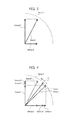
- FIG. 5 is a diagram showing a time variation in magnetic flux when the induction motor is accelerated from a non-excited state.
- FIG. 6 is a flowchart showing an operation of changing the excitation current command maximum value and the torque current command maximum value by the control device of the induction motor according to the embodiment of the present invention.
- FIG. 1 is a diagram showing the circuit configuration of the control device of an induction motor according to an embodiment of the present invention.
- the control device 1 shown in FIG. 1 is a device for driving the induction motor (hereinafter referred to as a “motor”) 2 which drives and rotates the spindle of a machine tool such as a spindle machine.
- the control device 1 performs vector control in which the primary current of the motor 2 , that is, a drive current is divided into an excitation (d phase) current for generation of a magnetic flux and a secondary current, that is, a torque (q phase) current and is controlled.
- the control device 1 includes a speed control portion 100 , a current control portion 200 and a drive portion 300 .
- the speed control portion 100 and the current control portion 200 are so-called numerical control devices which are formed with, for example, a computation processor such as a DSP (Digital Signal Processor) or an FPGA (Field-Programmable Gate Array).
- the functions of the speed control portion 100 and the current control portion 200 are realized by performing predetermined software (programs) stored in a storage portion (for example, a storage portion 214 which will be described later).
- the functions of the speed control portion 100 and the current control portion 200 may be realized by cooperation of hardware and software or may be realized only by hardware (electronic circuit).
- the speed control portion 100 reads a speed command value vcmd from a machining program stored in the storage portion (for example, the storage portion 214 which will be described later), and inputs the actual speed value va of the motor 2 which is detected by a speed detector 3 provided in the motor 2 .
- the speed control portion 100 generates a torque command value Tcmd based on a difference between the speed command value vcmd and the actual speed value va.
- the current control portion 200 inputs the torque command value Tcmd, the actual speed value va of the motor 2 , the output currents of the drive portion 300 which are detected by a current detector 301 provided in the drive portion 300 , that is, actual current values (drive currents) Iu, Iv and Iw for driving the motor 2 and the power supply voltage V of the drive portion 300 which is detected by a voltage detector 302 provided in the drive portion 300 .
- the current control portion 200 generates, based on the torque command value Tcmd, the actual speed value va, the actual. current values Iu, Iv and Iw and the power supply voltage V, voltage command values Vu, Vv and Vw for driving the drive portion 300 .
- the current control portion 200 includes a current command generation portion 210 , an excitation current control portion 221 , a torque current control portion 222 , a dq-uvw conversion portion 223 and a dq-uvw conversion portion 224 .
- the current command generation portion 210 generates an excitation current command value Idcmd and a torque current command value Iqcmd mainly based on the torque command value Tcmd. The details of the current command generation portion 210 will be described later.
- the excitation current control portion 221 generates a d phase voltage command value Vdcmd based on a difference between the excitation current command value Idcmd and a d phase actual current value Ida obtained by converting the actual current values Iu, Iv and Iw with the dq-uvw conversion portion 224 .
- the torque current control portion 222 generates a q phase voltage command value Vqcmd based on a difference between the torque current command value Iqcmd and a q phase actual current value Iqa obtained by converting the actual current values Iu, Iv and Iw with the dq-uvw conversion portion 224 .
- the dq-uvw conversion portion 223 converts the d phase voltage command value Vdcmd and the g phase voltage command value Vqcmd into the voltage command values Vu, Vv and Vw of the u, v and w phases.
- the dq-uvw conversion portion 224 converts the actual current values Iu, Iv and Iw of the u, v and w phases into the d phase actual current value Ida and the q phase actual current value Iqa.
- the drive portion 300 generates the actual current values (drive currents) Iu, Iv and Iw for driving the motor 2 based on the voltage command values Vu, Vv and Vw.
- the drive portion 300 is formed with a converter which converts commercial three phase alternating-current power into direct-current power and an inverter which converts the direct-current power from the converter into the three phase alternating-current power.
- the voltage command values Vu, Vv and Vw are used as control voltages for the inverter.
- the voltage detector 302 described previously may detect, as the power supply voltage V, for example, a direct-current voltage in a DC between the converter and the inverter.
- FIG. 2 is a diagram showing the circuit configuration of the current command generation portion 210 .
- the current command generation portion 210 shown in FIG. 2 includes a magnetic flux command computation portion 211 , an excitation current command generation portion 212 , a torque current command generation portion 213 , the storage portion 214 , a current frequency computation portion 215 , a magnetic flux estimation portion 216 , a determination portion 217 and a current command maximum value setting portion 218 .
- the magnetic flux command computation portion 211 generates a magnetic flux command value ⁇ cmd for generation of the magnetic flux of the motor 2 based on the torque command value Tcmd and the actual speed value va of the motor 2 .
- the excitation current command generation portion 212 generates the excitation current command value Idcmd based on the magnetic flux command value ⁇ cmd. When the generated excitation current command value Idcmd is higher than an excitation current command maximum value Idmax set by the current command maximum value setting portion 218 , the excitation current command generation portion 212 limits the excitation current command value Idcmd to the excitation current command maximum value Idmax.
- the torque current command generation portion 213 generates the torque current command value Iqcmd based on the torque command value Tcmd. When the generated torque current command value Iqcmd is higher than a torque current command maximum value Iqmax set by the current command maximum value setting portion 218 , the torque current command generation portion 213 limits the torque current command value Iqcmd to the torque current command maximum value Iqmax.
- the storage portion 214 stores a predetermined excitation current command maximum value Idmax 0 for a steady state where the speed of the motor 2 is constant and a predetermined torque current command maximum value Iqmax 0 .
- the storage portion 214 also stores various types of parameters such as an allowable maximum current value Imax 1 of the drive portion 300 , an excitation inductance L of the motor 2 , a mutual inductance M of the primary winding and the secondary winding of the motor 2 , a slip constant (slip coefficient) Ks of the motor 2 , the number P of polar pairs of the motor 2 , a time constant ⁇ which is determined by the circuit constant of the motor 2 and a constant K related to the vector control.
- the storage portion 214 may store the predetermined software (programs) for realizing the various types of functions of the speed control portion 100 and the current control portion 200 or may store the machining program including the speed command value vcmd.
- the storage portion 214 is a rewritable memory such as an EEPROM.
- the current frequency computation portion 215 determines a slip frequency fs [Hz] by formula (4) below based on the excitation current command value Idcmd, the torque current command value Iqcmd and the slip constant (slip coefficient) Ks of the motor 2 stored in the storage portion 214 .
- fs Iqcmd/Idcmd ⁇ Ks (4)
- the current frequency computation portion 215 determines a current frequency f [Hz] of the drive current of the motor 2 by formula (5) below based on the slip frequency fs, the actual speed value va [rpm] of the motor 2 and the number P of polar pairs of the motor 2 stored in the storage portion 214 .
- f va/ 60 ⁇ P+fs (5)
- the magnetic flux estimation portion 216 estimates the current amount ⁇ of magnetic flux by formula (6) below based on the excitation current command value Idcmd, the mutual inductance M of the motor 2 stored in the storage portion 214 , the time constant ⁇ determined by the circuit constant of the motor 2 and an elapsed time t after the determination portion 217 determines that the motor 2 is in an accelerated state.
- ⁇ M ⁇ Idcmd ⁇ (1 ⁇ e ⁇ t/ ⁇ ) (6)
- the determination portion 217 determines, based on a variation in the speed command value vcmd in the machining program stored in the storage portion 214 , whether the motor 2 is in an accelerated/decelerated state or in the steady state where the speed is constant. The determination portion 217 determines whether or not the current amount ⁇ of magnetic flux estimated by the magnetic flux estimation portion 216 reaches the magnetic flux command value ⁇ cmd.
- the current command maximum value setting portion 218 sets, based on the result of the determination by the determination portion 217 , the predetermined excitation current command maximum value Idmax 0 and the predetermined torque current command maximum value Iqmax 0 stored in the storage portion 214 to the excitation current command maximum value Idmax and the torque current command maximum value Iqmax, respectively.
- FIG. 3 is a diagram showing an example of the predetermined excitation current command maximum value Idmax 0 and the predetermined torque current command maximum value Iqmax 0 for the steady state where the speed of the motor 2 is constant.
- the predetermined excitation current command maximum value Idmax 0 and the predetermined torque current command maximum value Iqmax 0 are set such that the drive current value Imax 0 of the motor 2 is lower than the allowable maximum current value Imax 1 of the drive portion 300 .
- the predetermined torque current command maximum value Iqmax 0 is set to, for example, about twice to three times the predetermined excitation current command maximum value Idmax 0 .
- the current command maximum value setting portion 218 changes, based on the result of the determination by the determination portion 217 , instead of the predetermined excitation current command maximum value Idmax 0 , the excitation current command maximum value Idmax to a first excitation current command maximum value Idmax 1 or a second excitation current command maximum value Idmax 2 which will be described later.
- the current command maximum value setting portion 218 determines the first excitation current command maximum value Tdmax 1 by formula (1) below based on the allowable maximum current value Imax 1 of the drive portion 300 and the constant K related to the vector control stored in the storage portion 214 .
- Idmax1 Imax1/ K (1)
- the constant K related to the vector control is set to ⁇ (2) such that the torque of the motor 2 is maximized.
- the constant K is not limited to the present embodiment, and may be an arbitrary value.
- the current command maximum value setting portion 218 determines a second excitation current command maximum value Idmax 2 by formula (2) below based on the current frequency f computed by the current frequency computation portion 215 , the power supply voltage V detected by the voltage detector 302 and the excitation inductance L of the motor 2 stored in the storage portion 214 .
- Idmax2 V /(2 ⁇ f ⁇ L ) (2)
- the second excitation current command maximum value Idmax 2 is an upper limit for preventing voltage saturation where the power supply voltage V of the drive portion 300 is insufficient when the current frequency f of the drive current of the motor 2 is high, that is, when the motor 2 is operated at high speed.
- the current command maximum value setting portion 218 determines, as the excitation current command maximum value Idmax, which one of the first excitation current command maximum value Idmax 1 and the second excitation current command maximum value Idmax 2 is lower.
- FIG. 4 is a diagram showing an example of the first excitation current command maximum value Idmax 1 and a first torque current command maximum value Iqmax 1 (when Idmax 1 ⁇ Iqmax 2 ) and the second excitation current command maximum value Idmax 2 and a second torque current command maximum value Iqmax 2 (when Idmax 1 >Iqmax 2 ) for the accelerated/decelerated state of the motor 2 .
- the first excitation current command maximum value Idmax 1 and the second excitation current command maximum value Idmax 2 are higher than the Predetermined excitation current command maximum value Idmax 0 .
- the current command maximum value setting portion 218 determines the torque current command maximum value Iqmax by formula (3) below based on the excitation current command maximum value Idmax and the allowable maximum current value Imax 1 which are determined.
- Iqmax ⁇ ((Imax 1 2 ⁇ Idmax 2 ) (3) Specifically, as shown in FIG. 4 , when the excitation current command maximum value Idmax is set to the first excitation current command maximum value Idmax 1 , the torque current command maximum value Iqmax is set to the first torque current command maximum value Iqmax 1 whereas when the excitation current command maximum value Idmax is set to the second excitation current command maximum value Idmax 2 , the torque current command maximum value Iqmax is set to the second torque current command maximum value Iqmax 2 .
- upper limits are set for the excitation current command value and the torque current command value (for example, the predetermined excitation current command maximum value Idmax 0 and the predetermined torque current command maximum value Iqmax 0 described above).
- these maximum values are set such that the drive current of the motor (for example, Imax 0 in FIG. 3 ) is lower than the allowable maximum current value of the drive portion (for example, Imax 1 in FIG. 3 ).
- FIG. 5 is a diagram showing a time variation in the amount ⁇ of magnetic flux when the motor 2 is accelerated from a non-excited state.
- the magnetic flux rises at the time constant ⁇ determined by the circuit constant of the motor 2 (see formula (6) described previously).
- the rise of the magnetic flux until the magnetic flux reaches the desired amount ⁇ cmd of magnetic flux after the start of flow of the excitation current is slow.
- the excitation current command value Idcmd is limited to the predetermined excitation current command maximum value Idmax 0 , as shown in the curve A of FIG. 5 , the rise of the magnetic flux is slower.
- a time necessary to accelerate/decelerate the motor 2 is disadvantageously long.
- the excitation current command maximum value Idmax is changed to the first excitation current command maximum value Idmax 1 or the second excitation current command maximum value Idmax 2 which is higher than the predetermined excitation current command maximum value Idmax 0 .
- the rise of the magnetic flux can be speeded up, and thus it is possible to reduce the time necessary to accelerate/decelerate the motor 2 .
- FIG. 6 is a flowchart showing the operation of changing the excitation current command maximum value Idmax and the torque current command maximum value Iqmax by the control device 1 .
- the current frequency computation portion 215 first computes the current frequency f of the current drive current of the motor 2 by formulas (4) and (5) described previously (S 1 ).
- the voltage detector 302 detects the current power supply voltage V (S 1 ).
- the magnetic flux estimation portion 216 estimates the current amount ⁇ of magnetic flux by formula (6) described previously (S 1 ).
- the determination portion 217 determines, based on a variation in the speed command value vcmd, whether or not the motor 2 in the accelerated state (S 2 ).
- the determination portion 217 determines whether or not the current amount ⁇ of magnetic flux estimated by the magnetic flux estimation portion 216 is lower than the magnetic flux command value ⁇ cmd (S 3 ).
- the current command maximum value setting portion 218 sets the predetermined excitation current command maximum value Idmax 0 and the predetermined torque current command maximum value Iqmax 0 to the excitation current command maximum value Idmax and the torque current command maximum value Iqmax, respectively (S 4 ). Thereafter, the process returns to step S 1 .
- the current command maximum value setting portion 218 changes, instead of the predetermined excitation current command maximum value Idmax 0 , the excitation current command maximum value Idmax to the first excitation current command maximum value Idmax 1 or the second excitation current command maximum value Idmax 2 .
- the current command maximum value setting portion 218 determines, based on the allowable maximum current value Imax 1 of the drive portion 300 , the first excitation current command maximum value Idmax 1 by formula (1) described previously.
- the current command maximum value setting portion 218 also determines the second excitation current command maximum value Idmax 2 by formula (2) described previously based on the current frequency f of the drive current of the motor 2 , the power supply voltage V of the drive portion 300 and the excitation inductance L of the motor 2 .
- the current command maximum value setting portion 218 determines, as the excitation current command maximum value Idmax, which one of the first excitation current command maximum value Idmax 1 and the second excitation current command maximum value Idmax 2 is lower (S 5 ).
- the current command maximum value setting portion 218 determines the torque current command maximum value Iqmax by formula (3) described previously based on the excitation current command maximum value Idmax which are determined and the allowable maximum current value Imax 1 . Thereafter, the process returns to step S 1 .
- steps S 1 to S 6 are repeatedly performed, for example, at predetermined time intervals. In this way, the excitation current command maximum value Idmax and the torque current command maximum value Iqmax are adjusted sequentially.
- the second excitation current command maximum value Idmax 2 is varied depending on (in inverse proportion to) the current frequency f, that is, the actual speed value va of the motor 2 (see formulas (2) and (5) described previously), and thus when the speed of the motor 2 is low, Idmax 1 ⁇ Idmax 2 whereas when the speed of the motor 2 is high, Idmax 1 >Idmax 2 .
- the excitation current command maximum value Idmax is set to the first excitation current command maximum value Idmax 1 .
- the excitation current command maximum value Idmax is changed to the first excitation current command maximum value Idmax 1 higher than the predetermined excitation current command maximum value Idmax 0 .
- the rise of the magnetic flux can be speeded up.
- the torque current command maximum value Iqmax is changed to the first torque current command maximum value Iqmax 1 lower than the predetermined torque current command maximum value Iqmax 0 so as not to exceed the allowable maximum current value Imax 1 of the drive portion 300 .
- the rise of the magnetic flux can be speeded up while preventing the allowable maximum current value Imax 1 of the drive portion 300 from being exceeded, and thus it is possible to reduce the time until the desired amount ⁇ cmd of magnetic flux is generated.
- the excitation current command maximum value Idmax is set to the second excitation current command maximum value Idmax 2 .
- the second excitation current command maximum value Idmax 2 is gradually decreased as the speed of the motor 2 is raised as described previously (a direction D 1 indicated by an arrow of FIG. 4 , and thus the excitation current command maximum value Idmax is set lower gradually as the speed of the motor 2 is raised.
- the excitation current command maximum value Idmax is changed to the second excitation current command maximum value Idmax 2 to be gradually decreased, with the result that the amount ⁇ of magnetic flux can be made to converge to the desired amount ⁇ cmd of magnetic flux (a direction D 2 indicated by an arrow of FIG. 5 ).
- the torque current command maximum value Iqmax is set higher gradually as the speed of the motor 2 is raised so as not to exceed the allowable maximum current value Imax 1 of the drive portion 300 (the direction D 1 indicated by the arrow of FIG. 4 ).
- the increased excitation current command maximum value Idmax is returned so as to be gradually decreased
- the decreased torque current command maximum value Iqmax is returned so as to be gradually increased and thus it is possible to reduce the time until the desired torque is generated while preventing the allowable maximum current value Imax 1 of the drive portion 300 from being exceeded and preventing voltage saturation when the motor 2 operated at high speed.
- the distribution of the excitation current command maximum value Idmax and the torque current command maximum value Iqmax in the accelerated state of the motor 2 is changed sequentially to the distribution thereof in the steady state where the speed is constant, and thus it is possible to reduce the time until the desired amount ⁇ cmd of magnetic flux is generated and to reduce the time until the desired torque is generated. Consequently, it is possible to reduce the time necessary to accelerate/decelerate the motor 2 .
- steps S 2 and S 3 and S 5 and S 6 of FIG. 6 the operation when the motor 2 in the accelerated state is illustrated, the same is true for an operation when the motor 2 is in the decelerated state.
- the excitation current command maximum value Idmax is changed to the first excitation current command maximum value Idmax 1 based on the allowable maximum current value Imax 1 of the drive portion 300 or the second excitation current command maximum value Idmax 2 based on the power supply voltage V of the drive portion 300 , the current frequency f of the drive current of the motor 2 and the excitation inductance L of the motor 2 , and thus it is possible to increase the excitation current command maximum value Idmax as compared with the steady state where the speed is constant. In this way, it is possible to speed up the rise of the magnetic flux and to reduce the time necessary to accelerate/decelerate the motor 2 .
- the excitation current command maximum value Idmax is changed to which one of the first excitation current command maximum value Idmax 1 and the second excitation current command maximum value Idmax 2 is lower.
- the first excitation current command maximum value Idmax 1 is based on the allowable maximum current value Imax 1 of the drive portion 300 .
- the second excitation current command maximum value Idmax 2 is the upper limit for voltage saturation when the motor 2 is operated at high speed.
- the torque current command maximum value Iqmax is changed to the first torque current command maximum value Iqmax 1 or the second torque current command maximum value Iqmax 2 so as not to exceed the allowable maximum current value Imax 1 of the drive portion 300 . In this way, it is possible to speed up the rise of the magnetic flux while preventing the allowable maximum current value Imax 1 of the drive portion 300 from being exceeded and preventing voltage saturation when the motor 2 is operated at high speed.
- control device 1 of the present embodiment has the effects even when the motor is accelerated/decelerated from the state where the magnetic flux is low as described above. In other words, in the control device 1 of the present embodiment, it is possible to realize both the reduction of the heat generation of the motor 2 at the time of a light load and the reduction of the time necessary to accelerate/decelerate the motor 2 .
- the present invention is not limited to the embodiment described above.
- the effects described in the present embodiment are simply a list of the most preferred effects produced from the present invention, and the effects of the present invention are not limited to those described in the present embodiment.
- the first excitation current command maximum value Idmax 1 is determined based on the allowable maximum current value Imax 1 of the drive portion 300
- the first excitation current command maximum value Idmax 1 may be determined based on which one of the allowable maximum current value of the drive portion 300 and the allowable maximum current value of the motor 2 is lower.
- the allowable maximum current value of the motor 2 can be increased by a heat dissipation mechanism, and thus the allowable maximum current value of the drive portion 300 is often lower than the allowable maximum current value of the motor 2 .
- the current frequency f of the drive current of the motor 2 is determined based on the number P of polar pairs of the motor 2 (formula (5) described previously), instead of the number P of polar pairs, twice the value of the number of poles of the motor 2 may be used.
Landscapes
- Engineering & Computer Science (AREA)
- Power Engineering (AREA)
- Control Of Ac Motors In General (AREA)
- Inverter Devices (AREA)
Abstract
Description
Idmax1=Imax1×K (1),
may determine the second excitation current command maximum value Idmax2 by formula (2) below based on the power supply voltage V, the current frequency f and the excitation inductance L,
Idmax2=V/(2πf×L) (2),
may determine, as the excitation current command maximum value Idmax, which one of the first excitation current command maximum value Idmax1 and the second excitation current command maximum value Idmax2 is lower and may determine the torque current command maximum value Iqmax by formula (3) below based on the excitation current command maximum value Idmax which are determined and the allowable maximum current value Imax1,
Iqmax=√(Imax12−Idmax2) (3).
fs=Iqcmd/Idcmd×Ks (4)
The current
f=va/60×P+fs (5)
[Math. 1]
Φ=M×Idcmd×(1−e −t/τ) (6)
Idmax1=Imax1/K (1)
In the present embodiment, the constant K related to the vector control is set to √(2) such that the torque of the
Idmax2=V/(2πf×L) (2)
The second excitation current command maximum value Idmax2 is an upper limit for preventing voltage saturation where the power supply voltage V of the
Iqmax=√((Imax1 2−Idmax2) (3)
Specifically, as shown in
Claims (8)
Idmax1=Imax1×K (1),
Idmax2=V/(2πf×L) (2),
Iqmax=√(Imax12−Idmax2) (3).
Applications Claiming Priority (2)
| Application Number | Priority Date | Filing Date | Title |
|---|---|---|---|
| JP2017011170A JP6334017B1 (en) | 2017-01-25 | 2017-01-25 | Induction motor control device |
| JP2017-011170 | 2017-01-25 |
Publications (2)
| Publication Number | Publication Date |
|---|---|
| US20180212543A1 US20180212543A1 (en) | 2018-07-26 |
| US10224852B2 true US10224852B2 (en) | 2019-03-05 |
Family
ID=62238911
Family Applications (1)
| Application Number | Title | Priority Date | Filing Date |
|---|---|---|---|
| US15/876,639 Active 2038-04-10 US10224852B2 (en) | 2017-01-25 | 2018-01-22 | Control device of induction motor |
Country Status (4)
| Country | Link |
|---|---|
| US (1) | US10224852B2 (en) |
| JP (1) | JP6334017B1 (en) |
| CN (1) | CN108347208B (en) |
| DE (1) | DE102018200961A1 (en) |
Families Citing this family (2)
| Publication number | Priority date | Publication date | Assignee | Title |
|---|---|---|---|---|
| JP6949814B2 (en) * | 2018-12-20 | 2021-10-13 | ファナック株式会社 | Parameter determination support device, parameter determination support method, and program |
| US10938332B1 (en) * | 2019-10-07 | 2021-03-02 | Caterpillar Inc. | Modified flux observer for switched reluctance machines |
Citations (7)
| Publication number | Priority date | Publication date | Assignee | Title |
|---|---|---|---|---|
| JPS60200791A (en) | 1984-03-26 | 1985-10-11 | Mitsubishi Electric Corp | Induction motor speed control device |
| JPH02111282A (en) | 1988-10-19 | 1990-04-24 | Fuji Electric Co Ltd | Controller of induction motor |
| US5446363A (en) * | 1993-02-05 | 1995-08-29 | Kabushiki Kaisha Toshiba | Method of controlling induction motor |
| US5475293A (en) * | 1992-09-16 | 1995-12-12 | Hitachi, Ltd. | Method for measuring characteristic constants of alternating current motor and controller thereof based on said method |
| US5629598A (en) * | 1993-05-21 | 1997-05-13 | Wilkerson; Alan W. | Speed control for induction motor having improved sensing of motor operative conditions |
| US20080303476A1 (en) * | 2007-06-05 | 2008-12-11 | Fanuc Ltd | Electric motor control device |
| US20110204831A1 (en) * | 2010-02-25 | 2011-08-25 | Hitachi, Ltd. | Drive device for alternating current motor and electric motor vehicle |
Family Cites Families (7)
| Publication number | Priority date | Publication date | Assignee | Title |
|---|---|---|---|---|
| JP2646633B2 (en) * | 1988-03-26 | 1997-08-27 | 株式会社安川電機 | Calculation method of magnetic flux of induction motor |
| JPH08130900A (en) * | 1994-11-01 | 1996-05-21 | Fanuc Ltd | Method and device for controlling induction motor |
| JP4553434B2 (en) * | 2000-01-17 | 2010-09-29 | 東洋電機製造株式会社 | Inverter device with constant measurement setting function |
| GB2426581A (en) * | 2005-05-27 | 2006-11-29 | Univ Nottingham | Immunoassay methods |
| CN101989831B (en) * | 2009-07-31 | 2012-07-11 | 上海三菱电梯有限公司 | Induction motor control device and its application |
| JP5516087B2 (en) * | 2010-06-01 | 2014-06-11 | 富士電機株式会社 | Induction motor control method |
| JP5842487B2 (en) * | 2011-09-08 | 2016-01-13 | 日産自動車株式会社 | Motor control device |
-
2017
- 2017-01-25 JP JP2017011170A patent/JP6334017B1/en active Active
-
2018
- 2018-01-22 US US15/876,639 patent/US10224852B2/en active Active
- 2018-01-22 CN CN201810058500.9A patent/CN108347208B/en active Active
- 2018-01-23 DE DE102018200961.9A patent/DE102018200961A1/en active Pending
Patent Citations (7)
| Publication number | Priority date | Publication date | Assignee | Title |
|---|---|---|---|---|
| JPS60200791A (en) | 1984-03-26 | 1985-10-11 | Mitsubishi Electric Corp | Induction motor speed control device |
| JPH02111282A (en) | 1988-10-19 | 1990-04-24 | Fuji Electric Co Ltd | Controller of induction motor |
| US5475293A (en) * | 1992-09-16 | 1995-12-12 | Hitachi, Ltd. | Method for measuring characteristic constants of alternating current motor and controller thereof based on said method |
| US5446363A (en) * | 1993-02-05 | 1995-08-29 | Kabushiki Kaisha Toshiba | Method of controlling induction motor |
| US5629598A (en) * | 1993-05-21 | 1997-05-13 | Wilkerson; Alan W. | Speed control for induction motor having improved sensing of motor operative conditions |
| US20080303476A1 (en) * | 2007-06-05 | 2008-12-11 | Fanuc Ltd | Electric motor control device |
| US20110204831A1 (en) * | 2010-02-25 | 2011-08-25 | Hitachi, Ltd. | Drive device for alternating current motor and electric motor vehicle |
Also Published As
| Publication number | Publication date |
|---|---|
| CN108347208B (en) | 2019-04-19 |
| US20180212543A1 (en) | 2018-07-26 |
| CN108347208A (en) | 2018-07-31 |
| DE102018200961A1 (en) | 2018-07-26 |
| JP2018121437A (en) | 2018-08-02 |
| JP6334017B1 (en) | 2018-05-30 |
Similar Documents
| Publication | Publication Date | Title |
|---|---|---|
| JP5084973B1 (en) | Motor control device | |
| JP6143984B1 (en) | Inverter device | |
| CN109687793B (en) | Motor control device | |
| US20190238079A1 (en) | Motor controller | |
| US10224852B2 (en) | Control device of induction motor | |
| Sergaki et al. | Online search based fuzzy optimum efficiency operation in steady and transient states for DC and AC vector controlled motors | |
| Popov et al. | Dynamic operation of FOC induction machines under current and voltage constraints | |
| JP6681653B2 (en) | Synchronous motor controller | |
| CN109687794B (en) | Motor control device | |
| EP1594220A1 (en) | Ac motor control method and control device | |
| JP5932136B2 (en) | Motor control device | |
| US8466643B2 (en) | Motor drive device, and motor drive method | |
| US20150194921A1 (en) | Motor control device capable of switching between application and non-application of magnetic flux control | |
| Ammar et al. | Implementation of sliding mode based-direct flux and torque control for induction motor drive with efficiency optimization | |
| JP2007049798A (en) | Power conversion equipment | |
| JPH06253575A (en) | Vector control inverter device for induction motor | |
| JP4027760B2 (en) | Inverter control device | |
| US11296625B2 (en) | Control device and control method for synchronous electric motor | |
| JP6737720B2 (en) | Induction motor speed controller | |
| JP4061517B2 (en) | AC motor variable speed controller | |
| JPH07163188A (en) | Torque boost controller for induction motor | |
| Yoo et al. | Sensorless torque control of induction machine in low speed and low torque region | |
| WO2025099907A1 (en) | Machine tool control device | |
| JP2005295800A (en) | Control system for induction motor | |
| JP2005348551A (en) | Induction motor speed control device |
Legal Events
| Date | Code | Title | Description |
|---|---|---|---|
| AS | Assignment |
Owner name: FANUC CORPORATION, JAPAN Free format text: ASSIGNMENT OF ASSIGNORS INTEREST;ASSIGNOR:MORITA, YUUKI;REEL/FRAME:044690/0475 Effective date: 20180119 |
|
| FEPP | Fee payment procedure |
Free format text: ENTITY STATUS SET TO UNDISCOUNTED (ORIGINAL EVENT CODE: BIG.); ENTITY STATUS OF PATENT OWNER: LARGE ENTITY |
|
| STCF | Information on status: patent grant |
Free format text: PATENTED CASE |
|
| MAFP | Maintenance fee payment |
Free format text: PAYMENT OF MAINTENANCE FEE, 4TH YEAR, LARGE ENTITY (ORIGINAL EVENT CODE: M1551); ENTITY STATUS OF PATENT OWNER: LARGE ENTITY Year of fee payment: 4 |