US1022093A - Machine for artificially lengthening the barbs of ornamental feathers. - Google Patents
Machine for artificially lengthening the barbs of ornamental feathers. Download PDFInfo
- Publication number
- US1022093A US1022093A US61031611A US1911610316A US1022093A US 1022093 A US1022093 A US 1022093A US 61031611 A US61031611 A US 61031611A US 1911610316 A US1911610316 A US 1911610316A US 1022093 A US1022093 A US 1022093A
- Authority
- US
- United States
- Prior art keywords
- barbs
- machine
- cylinder
- feathers
- lever
- Prior art date
- Legal status (The legal status is an assumption and is not a legal conclusion. Google has not performed a legal analysis and makes no representation as to the accuracy of the status listed.)
- Expired - Lifetime
Links
- 210000003746 feather Anatomy 0.000 title description 14
- 101100001672 Emericella variicolor andG gene Proteins 0.000 description 1
- 241000272534 Struthio camelus Species 0.000 description 1
- 230000002708 enhancing effect Effects 0.000 description 1
- 238000000034 method Methods 0.000 description 1
- 230000007306 turnover Effects 0.000 description 1
Images


Classifications
-
- A—HUMAN NECESSITIES
- A41—WEARING APPAREL
- A41G—ARTIFICIAL FLOWERS; WIGS; MASKS; FEATHERS
- A41G9/00—Adornments of natural feathers; Working natural feathers
-
- B—PERFORMING OPERATIONS; TRANSPORTING
- B65—CONVEYING; PACKING; STORING; HANDLING THIN OR FILAMENTARY MATERIAL
- B65H—HANDLING THIN OR FILAMENTARY MATERIAL, e.g. SHEETS, WEBS, CABLES
- B65H2701/00—Handled material; Storage means
- B65H2701/30—Handled filamentary material
- B65H2701/31—Textiles threads or artificial strands of filaments
Definitions
- the present invention relates to a machine for lengthening the barbs of ornamental feathers, as for instance ostrich feathers by connecting others to them with a view to enhancing their decorative appearance.
- the machine is adapted to do the work previously done by hand, which is extremely laborious and difiicult owing to the delicate material, and to do it more rapidly and uniformly by curling the barbs of the feathers into loops which are then pulled into a knot by hand.
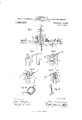
- FIG. 1 is a side view
- Fig. 2 a plan
- Fig. 3 shows the driving mechanism
- Fig. 4t is a front view, showing especially the mechanism for forming the loop.
- Figs. 5 and 6 show details of the latter, partly in section.
- Fig. 7 is a side view similar to Fig. 1 with the actuating device in working position.
- Figs. 8 to 11 illustrate various positions of the loop-forming device, and Figs. 12 and 13 show the loop and the tied knot respectively.
- a slide 6 Arranged on a base plate 1, having a slot 2, is a slide 6 movable between guides 3, 4: and acted on by the spring 5; this slide is connected to a driving cord 8 running over a pulley 7.
- the slide 6 (Fig. 3) has at its front end a movable lever 9 projecting through the slot in the base plate, and it is provided centrally with a stepped rack 10 and carries at its rear end a wiper 11 and a bearing block 12 to which is secured a pivoted lever 13 and a striker 1 1.
- a stop 15 having a padded surface is provided at both ends of the base plate 1 for the purpose of limiting the movement of the slide (5.
- the loop by means of which the two feather barbs are knotted together is formed by the rotatable and vertically moving hollow body 16 with which is connected a clamp 17 which with the aid of the clamping device 18, opposite the cylinder 16, is adapted to hold the barbs while the loop is being formed.
- the hollow body 16 (see Fig. 5) is arranged on a hollow shaft 19 fixed to the base plate 1.
- a helmet shaped head provided with a longitudinal slot 20, (Figs. 8 to 11) and keyed to its lower end is a toothed wheel 22 which is adapted to be rotated by the stepped rack 10 on the slide 6.
- this toothed wheel At a suitable distance above this toothed wheel is a cup shaped disk 23 which serves to lift the cylinder 16 by acting as a tappet for the bent lever 25 secured to the bearing block 24 on the base plate 1 (see Figs. 1 and 7), said lever 25 being actuated by the lever 13 when the slide 6 moves forward.
- a spring 26 engages the disk 23 and is provided with a boss at its free end adapted to engage a depression in the disk 23 when the cylinder 16 is in its raised position, whereby the cylinder is prevented from turning back.
- the clamp 17 at the side of the hollow body is a spring-actuated bell-crank lever, the lower arm 27 of which has an inclined surface adapted to be engaged by the wiper 14 on the slide 6.
- a reciprocating pin 28 which carries, at the end passing through the base plate 1, a projection 29 which is engaged by the slanting spring actuated lever 30, the upper part of which is pivoted near the base plate 1 to the plate 31.
- the pin 28 is operated by the lever 9 striking the lever 30 when the slide 6 is in motion (Fig. 7
- the holding device 18 (Figs. 41 andG) comprises a clamp with spring-pressed arms 32, 33. The first of these arms is connected with a movable lever 35 which is influenced by the spring 3 1-. This lever projects through the plate 1 and is pivoted to a plate 36.
- the other arm 33 is angular and carries at its lower end a roller 37 which is adapted, by running on the wiper 11, to open the clamp and thereby release the barbs of the feather.
- the feathers which are to be lengthened can be held during the looping process by a suitable holding device fitted upon the machine, which is not shown on the drawing.
- the loops, by means of which the barbs are tied together, are formed in the following manner. The two ends of the barbs a and Z) to be tied together are on the one hand clamped in the clamp 18 and on the other hand in the clamp 17 secured to the cylinder 16 (see Figs. 1 and 8).
- This machine which may be used anywhere where it is desired to tie the ends of barbs together, is fastened on a table. It is covered by a case in such manner that when working only the upper part of the clamp 18 and the head of the cylinder 16 is visible,
- a machine for tying additional barb lengths to the barbs of ornamental feathers characterized by a rotating and vertically moving hollow cylinder with a head provided on one side with a longitudinal slot, in combination with a pin capable of sliding axially therein.
- a machine for tying additional barb lengths to the barbs of ornamental feathers characterized by a rotating and vertically moving hollow cylinder with a head provided on one side with a longitudinal slot in combination with a pin capable of sliding axially therein and a holding device for the ends of the barbs, comprising a bell-crank lever secured to a hollow cylinder and a shearlike clamp opposite the cylinder and adapted to move toward the latter.
- a machine for tying additional barb lengths to the barbs of ornamental feathers characterized by a rotating and vertically moving hollow cylinder with a head provided on one side with a longitudinal slot in combination with a pin capable of sliding axially therein and holding devices for the ends of the barbs, a lever to move the cylinder and the pin vertically and a longitudinal sliding spring operated slide provided with a stepped rack adapted to turn the cylinder and provided with wipers adapted to strike and actuate said lever to move the cylinder and pin vertically.
- a machine for tying additional barb lengths to the barbs of ornamental feathers characterized by a rotating and vertically moving hollow cylinder with a head provided on one side with a longitudinal slot in combination with a pin capable of sliding axially therein, holding devices comprising a lever mounted on the cylinder and a clamp for the ends of the barbs and a longitudinally sliding spring operated slide, said slide being provided with stepped rack to rotate the cylinder, wipers to rotate the cylinder and adapted to actuate said lever on the cylinder and to actuate said clamp to cause said lever and said clamp to open and release the ends of the barbs.
Landscapes
- Engineering & Computer Science (AREA)
- Textile Engineering (AREA)
- Basic Packing Technique (AREA)
Description
H. KRIEGSMANN.
MACHINE FOR ARTIPIGI ALLY LENGTHBNING THE BARBS 0F ORNAMENTAL FEATHERS. APPLIOATION FILED mums, 1911.
1,022,093, Patented Apr. 2, 1912.
3 SHEETS-SHEET 1.
common Pummlmvn CUuWASHINIITU-N, n. c.
H. KRIBGSMANN. MACHINE FOR ARTIFIGIALLY LENGTHENING THE BARBS 0F ORNAMENTAL FEATHEBS. APPLICATION FILED IEB.23, 1911.
1,022,093, Patented Apr. 2, 1912.
\ wvemroR I I M Ma W COLUMBIA PLANOORAPII CO.,WASN1NOTON, I). C.
H. KRIEGSMANN. MACHINE FOR ARTIFICIALLY LENGTHENING THE BARBS 0F ORNAMBNTAL FEATHERS..
APPLIOATION IILED PEB.23, 1911.
Patented Apr. 2, 1912.
3 SHEETS-SHEET 3.
WITNESSES! HANS KR IEGSMANN, OF LEIPZIGANGER, GERMANY.
MACHINE FOR ARTIFICIALLY LENGTHENING THE BARBS OF ORNAMENTAL FEATHERS.
Application filed February 23, 1911.
Specification of Letters Patent.
Patented Apr. 2, 1912-.
Serial No. 610,316.
To all whom it may concern:
Be it known that I, Hans KRInosMANN, merchant, subject of the King of Saxony, residing at 10 \Vurzenerstrasse, Leipzig-Anger, Germany, have invented new and useful Improvements in Machines for Artificially Lengthening the Barbs of Ornamental Feathers, of which the following is a specification.
The present invention relates to a machine for lengthening the barbs of ornamental feathers, as for instance ostrich feathers by connecting others to them with a view to enhancing their decorative appearance.
The machine is adapted to do the work previously done by hand, which is extremely laborious and difiicult owing to the delicate material, and to do it more rapidly and uniformly by curling the barbs of the feathers into loops which are then pulled into a knot by hand.
The machine is illustrated in the accompanying drawings in which Figure 1 is a side view, and Fig. 2 a plan. Fig. 3 shows the driving mechanism. Fig. 4t is a front view, showing especially the mechanism for forming the loop. Figs. 5 and 6 show details of the latter, partly in section. Fig. 7 is a side view similar to Fig. 1 with the actuating device in working position. Figs. 8 to 11 illustrate various positions of the loop-forming device, and Figs. 12 and 13 show the loop and the tied knot respectively.
Arranged on a base plate 1, having a slot 2, is a slide 6 movable between guides 3, 4: and acted on by the spring 5; this slide is connected to a driving cord 8 running over a pulley 7. The slide 6 (Fig. 3) has at its front end a movable lever 9 projecting through the slot in the base plate, and it is provided centrally with a stepped rack 10 and carries at its rear end a wiper 11 and a bearing block 12 to which is secured a pivoted lever 13 and a striker 1 1. A stop 15 having a padded surface is provided at both ends of the base plate 1 for the purpose of limiting the movement of the slide (5.
The loop by means of which the two feather barbs are knotted together is formed by the rotatable and vertically moving hollow body 16 with which is connected a clamp 17 which with the aid of the clamping device 18, opposite the cylinder 16, is adapted to hold the barbs while the loop is being formed. The hollow body 16 (see Fig. 5) is arranged on a hollow shaft 19 fixed to the base plate 1. At the top said body 16 is a helmet shaped head provided with a longitudinal slot 20, (Figs. 8 to 11) and keyed to its lower end is a toothed wheel 22 which is adapted to be rotated by the stepped rack 10 on the slide 6. At a suitable distance above this toothed wheel is a cup shaped disk 23 which serves to lift the cylinder 16 by acting as a tappet for the bent lever 25 secured to the bearing block 24 on the base plate 1 (see Figs. 1 and 7), said lever 25 being actuated by the lever 13 when the slide 6 moves forward. A spring 26 engages the disk 23 and is provided with a boss at its free end adapted to engage a depression in the disk 23 when the cylinder 16 is in its raised position, whereby the cylinder is prevented from turning back. The clamp 17 at the side of the hollow body is a spring-actuated bell-crank lever, the lower arm 27 of which has an inclined surface adapted to be engaged by the wiper 14 on the slide 6. Inside the hollow shaft 19 is a reciprocating pin 28 which carries, at the end passing through the base plate 1, a projection 29 which is engaged by the slanting spring actuated lever 30, the upper part of which is pivoted near the base plate 1 to the plate 31. The pin 28 is operated by the lever 9 striking the lever 30 when the slide 6 is in motion (Fig. 7 The holding device 18 (Figs. 41 andG) comprises a clamp with spring-pressed arms 32, 33. The first of these arms is connected with a movable lever 35 which is influenced by the spring 3 1-. This lever projects through the plate 1 and is pivoted to a plate 36. The other arm 33 is angular and carries at its lower end a roller 37 which is adapted, by running on the wiper 11, to open the clamp and thereby release the barbs of the feather. The feathers which are to be lengthened can be held during the looping process by a suitable holding device fitted upon the machine, which is not shown on the drawing. The loops, by means of which the barbs are tied together, are formed in the following manner. The two ends of the barbs a and Z) to be tied together are on the one hand clamped in the clamp 18 and on the other hand in the clamp 17 secured to the cylinder 16 (see Figs. 1 and 8). Then the cord 8 is pulled in the direction of the arrow by means of a pedal, not shown in the drawings whereby the slide 6 is moved forward 1 between the guide bars 3 and 1. During this movement the first step of the rack 10 engages the pinion 22 on the cylinder 16, this causing the latter to rotate around the hollow shaft 19. This rotation causes the clamped feather barbs to curl around the thinnest part of the cap 21, whereby the clamp 18 is pulled toward the cylinder 16 (see Fig. 9). The lever 13 on the slide 6 having participated in the movement of the latter moves farther forward and striking the curved lever 25 presses it against the disk 28 in the cylinder, whereby the latter is lifted (see Figs. 7 and 4). As the cylinder is further rotated by the second step of the rack 10, the next turn in the barb is placed in the recess underneath the cap 21 (see Figs. 5 and 10). The last teeth of the rack have now passed beyond the pinion 22 and the cylinder 16 is held fast by the spring 26 (see Figs. 1 and 3) which always rests on the disk 23. As the slide 6 continues to move forward in the direction indicated by the arrow the lever 9 (see Fig. 7) and the wiper 11 which are also secured to the slide 6 now come into operation. The lever 9 strikes the rear part of the spring influenced lever 30 and pressing the latter upward also raises the pin 28, sliding vertically in the hollow shaft 19 (see Figs. 5 and 7). As the pin 28 rises it pushes up the ends of the barbs which lie in the recess underneath the cap 21 (see Fig. 11) and are released at this moment by the clamp 18 owing to the roller 37 on the arm 83 running on the surface 11. The operator attending the machine takes hold of these ends a and 6 (see Fig. 12) and in pulling them away knots the loop formed thereby (see Fig. 18). The ends of the barbs which have been pushed up by the pin 28 are withdrawn from the cap 21 by passing through the slot 20. Now the clamp 17 is opened by the wiper 14 on the bearing block 12 pulling down the horizontal arm 27 of the clamp. If the pedal is now released the slide 6 is pulled back by the spring 5 put under tension in the first instance by the depression of the pedal. During this rearward movement the levers 9 and 18 turn over into their sliding off position and release the parts adapted to be operated by them. The rack 10 again engages the pinion 22 and turns the cylinder back to its position of rest. The plate 11 is simultaneously pulled back from underneath the roller 37 and the clamping mechanism is pulled back by the spring 34 into its original position.
This machine, which may be used anywhere where it is desired to tie the ends of barbs together, is fastened on a table. It is covered by a case in such manner that when working only the upper part of the clamp 18 and the head of the cylinder 16 is visible,
which parts may, however, also be covered when the machine is not in use.
Having now particularly described and ascertained the nature of my said invention and in what manner the same is to be performed, I declare that what I claim is:
1. A machine for tying additional barb lengths to the barbs of ornamental feathers characterized by a rotating and vertically moving hollow cylinder with a head provided on one side with a longitudinal slot, in combination with a pin capable of sliding axially therein.
2. A machine for tying additional barb lengths to the barbs of ornamental feathers characterized by a rotating and vertically moving hollow cylinder with a head provided on one side with a longitudinal slot in combination with a pin capable of sliding axially therein and a holding device for the ends of the barbs, comprising a bell-crank lever secured to a hollow cylinder and a shearlike clamp opposite the cylinder and adapted to move toward the latter.
3. A machine for tying additional barb lengths to the barbs of ornamental feathers characterized by a rotating and vertically moving hollow cylinder with a head provided on one side with a longitudinal slot in combination with a pin capable of sliding axially therein and holding devices for the ends of the barbs, a lever to move the cylinder and the pin vertically and a longitudinal sliding spring operated slide provided with a stepped rack adapted to turn the cylinder and provided with wipers adapted to strike and actuate said lever to move the cylinder and pin vertically.
4. A machine for tying additional barb lengths to the barbs of ornamental feathers characterized by a rotating and vertically moving hollow cylinder with a head provided on one side with a longitudinal slot in combination with a pin capable of sliding axially therein, holding devices comprising a lever mounted on the cylinder and a clamp for the ends of the barbs and a longitudinally sliding spring operated slide, said slide being provided with stepped rack to rotate the cylinder, wipers to rotate the cylinder and adapted to actuate said lever on the cylinder and to actuate said clamp to cause said lever and said clamp to open and release the ends of the barbs.
In testimony whereof I have signed my name to this specification in the presence of two subscribing witnesses.
HANS KRIEGSMANN.
lVitnesses ALBERT R. MoRAWETZ, RUDOLPH FRIoKn.
Copies of this patent may be obtained for five cents each, by addressing the Commissioner of Patents, Washington, D. G.
Priority Applications (1)
| Application Number | Priority Date | Filing Date | Title |
|---|---|---|---|
| US61031611A US1022093A (en) | 1911-02-23 | 1911-02-23 | Machine for artificially lengthening the barbs of ornamental feathers. |
Applications Claiming Priority (1)
| Application Number | Priority Date | Filing Date | Title |
|---|---|---|---|
| US61031611A US1022093A (en) | 1911-02-23 | 1911-02-23 | Machine for artificially lengthening the barbs of ornamental feathers. |
Publications (1)
| Publication Number | Publication Date |
|---|---|
| US1022093A true US1022093A (en) | 1912-04-02 |
Family
ID=3090390
Family Applications (1)
| Application Number | Title | Priority Date | Filing Date |
|---|---|---|---|
| US61031611A Expired - Lifetime US1022093A (en) | 1911-02-23 | 1911-02-23 | Machine for artificially lengthening the barbs of ornamental feathers. |
Country Status (1)
| Country | Link |
|---|---|
| US (1) | US1022093A (en) |
-
1911
- 1911-02-23 US US61031611A patent/US1022093A/en not_active Expired - Lifetime
Similar Documents
| Publication | Publication Date | Title |
|---|---|---|
| US2346786A (en) | Tying machine | |
| US1839854A (en) | Automatic operator for sewing machines | |
| US642870A (en) | Tag-machine. | |
| US329521A (en) | Shoe tying and knotting machine | |
| US1175290A (en) | Broom-sewing machine. | |
| US188629A (en) | Improvement in grain-binders | |
| US365651A (en) | Office | |
| US950667A (en) | Machine for cording shipping-tags. | |
| US174255A (en) | Improvement in grain-binders | |
| US515143A (en) | Tying machine | |
| US1594934A (en) | Tying-in machine | |
| US1065058A (en) | Machine for sewing linings to articles of clothing. | |
| US1190392A (en) | Vegetable-binder. | |
| US1219997A (en) | Book-sewing machine. | |
| US438448A (en) | Ors to f | |
| US662469A (en) | Machine for making card-clothing. | |
| US1929347A (en) | Automatic fastening apparatus which tautens, fastens, and cuts the wire in one sole operation | |
| US1098308A (en) | Apparatus for piecing warp-threads. | |
| GB191102631A (en) | A Machine for Artificially Lengthening the Barbs of Ornamental Feathers. | |
| US1167713A (en) | Broom-sewing machine. | |
| US1239793A (en) | Knot-tying device for grain-binders. | |
| US761231A (en) | Bale-tie machine. | |
| US139745A (en) | Improvement in sewing-machines | |
| US6099A (en) | Improvement in sewing-machines | |
| US468465A (en) | Machine for knotting the ends of spiral springs |