US10220249B1 - Treadmill with a track-type walking belt - Google Patents
Treadmill with a track-type walking belt Download PDFInfo
- Publication number
- US10220249B1 US10220249B1 US15/784,244 US201715784244A US10220249B1 US 10220249 B1 US10220249 B1 US 10220249B1 US 201715784244 A US201715784244 A US 201715784244A US 10220249 B1 US10220249 B1 US 10220249B1
- Authority
- US
- United States
- Prior art keywords
- chains
- treadmill
- inner plates
- connecting member
- slide rails
- Prior art date
- Legal status (The legal status is an assumption and is not a legal conclusion. Google has not performed a legal analysis and makes no representation as to the accuracy of the status listed.)
- Expired - Fee Related
Links
Images

Classifications
-
- A—HUMAN NECESSITIES
- A63—SPORTS; GAMES; AMUSEMENTS
- A63B—APPARATUS FOR PHYSICAL TRAINING, GYMNASTICS, SWIMMING, CLIMBING, OR FENCING; BALL GAMES; TRAINING EQUIPMENT
- A63B22/00—Exercising apparatus specially adapted for conditioning the cardio-vascular system, for training agility or co-ordination of movements
- A63B22/02—Exercising apparatus specially adapted for conditioning the cardio-vascular system, for training agility or co-ordination of movements with movable endless bands, e.g. treadmills
- A63B22/0285—Physical characteristics of the belt, e.g. material, surface, indicia
-
- A—HUMAN NECESSITIES
- A63—SPORTS; GAMES; AMUSEMENTS
- A63B—APPARATUS FOR PHYSICAL TRAINING, GYMNASTICS, SWIMMING, CLIMBING, OR FENCING; BALL GAMES; TRAINING EQUIPMENT
- A63B22/00—Exercising apparatus specially adapted for conditioning the cardio-vascular system, for training agility or co-ordination of movements
- A63B22/02—Exercising apparatus specially adapted for conditioning the cardio-vascular system, for training agility or co-ordination of movements with movable endless bands, e.g. treadmills
- A63B2022/0278—Exercising apparatus specially adapted for conditioning the cardio-vascular system, for training agility or co-ordination of movements with movable endless bands, e.g. treadmills with reversible direction of the running surface
-
- B—PERFORMING OPERATIONS; TRANSPORTING
- B65—CONVEYING; PACKING; STORING; HANDLING THIN OR FILAMENTARY MATERIAL
- B65G—TRANSPORT OR STORAGE DEVICES, e.g. CONVEYORS FOR LOADING OR TIPPING, SHOP CONVEYOR SYSTEMS OR PNEUMATIC TUBE CONVEYORS
- B65G17/00—Conveyors having an endless traction element, e.g. a chain, transmitting movement to a continuous or substantially-continuous load-carrying surface or to a series of individual load-carriers; Endless-chain conveyors in which the chains form the load-carrying surface
- B65G17/06—Conveyors having an endless traction element, e.g. a chain, transmitting movement to a continuous or substantially-continuous load-carrying surface or to a series of individual load-carriers; Endless-chain conveyors in which the chains form the load-carrying surface having a load-carrying surface formed by a series of interconnected, e.g. longitudinal, links, plates, or platforms
- B65G17/067—Conveyors having an endless traction element, e.g. a chain, transmitting movement to a continuous or substantially-continuous load-carrying surface or to a series of individual load-carriers; Endless-chain conveyors in which the chains form the load-carrying surface having a load-carrying surface formed by a series of interconnected, e.g. longitudinal, links, plates, or platforms the load carrying surface being formed by plates or platforms attached to more than one traction element
-
- B—PERFORMING OPERATIONS; TRANSPORTING
- B65—CONVEYING; PACKING; STORING; HANDLING THIN OR FILAMENTARY MATERIAL
- B65G—TRANSPORT OR STORAGE DEVICES, e.g. CONVEYORS FOR LOADING OR TIPPING, SHOP CONVEYOR SYSTEMS OR PNEUMATIC TUBE CONVEYORS
- B65G17/00—Conveyors having an endless traction element, e.g. a chain, transmitting movement to a continuous or substantially-continuous load-carrying surface or to a series of individual load-carriers; Endless-chain conveyors in which the chains form the load-carrying surface
- B65G17/30—Details; Auxiliary devices
- B65G17/38—Chains or like traction elements; Connections between traction elements and load-carriers
- B65G17/42—Attaching load carriers to traction elements
-
- B—PERFORMING OPERATIONS; TRANSPORTING
- B65—CONVEYING; PACKING; STORING; HANDLING THIN OR FILAMENTARY MATERIAL
- B65G—TRANSPORT OR STORAGE DEVICES, e.g. CONVEYORS FOR LOADING OR TIPPING, SHOP CONVEYOR SYSTEMS OR PNEUMATIC TUBE CONVEYORS
- B65G23/00—Driving gear for endless conveyors; Belt- or chain-tensioning arrangements
- B65G23/02—Belt- or chain-engaging elements
- B65G23/04—Drums, rollers, or wheels
- B65G23/06—Drums, rollers, or wheels with projections engaging abutments on belts or chains, e.g. sprocket wheels
Definitions
- the present invention relates to an exercising device and, more particularly, to a treadmill.
- a conventional treadmill comprises a track-type walking belt and a transmission mechanism for driving and rotating the walking belt.
- the transmission mechanism includes a plurality of rolling members located at two sides of the walking belt.
- the transmission mechanism further includes a pair of front rotation members and a pair of rear rotation members mounted on two opposite ends of a support rack.
- the walking belt is mounted around the front rotation members and the rear rotation members to rotate in an endless manner.
- Each of the front rotation members has a periphery provided with a plurality of recessed portions.
- Each of the recessed portions has an outside provided with an opening with a diameter smaller than that of each of the recessed portions.
- Each of the rolling members is received in one of the recessed portions and has a screwing member with a head received in the respective opening.
- each of the rolling members is a ball bearing made of iron, thereby increasing the cost of fabrication.
- each of the front rotation members is formed with the recessed portions and the openings by a lathe working procedure, thereby increasing the working cost.
- the primary objective of the present invention is to provide a treadmill with a track-type walking belt.
- a treadmill comprising a frame having two sides each provided with two sprockets, two slide rails mounted on the two sides of the frame, two chains engaging with the two sprockets at the two sides of the frame respectively and corresponding to the two slide rails respectively, a plurality of elongate board mounted between the two chains, and a plurality of rollers mounted on each of the two chains.
- Each of the elongate board has two ends each provided with a connecting member connected with one of the two chains. The rollers on each of the two chains rest on one of the two slide rails. When the two chains are rotated, the rollers on each of the two chains slide on one of the two slide rails.
- Each of the two chains includes a plurality of chain sets.
- Each of the chain sets includes two first inner plates mounted on the respective connecting member of one of the elongate board, two second inner plates spaced from the two first inner plates, two reinforcing spacers each mounted between one of the two first inner plates and one of the two second inner plates, an outer plate linking the two second inner plates, and two shafts each extending through the outer plate, one of the two second inner plates, one of the two reinforcing spacers, one of the two first inner plates and the respective connecting member of one of the elongate board.
- the two chains engage with the two sprockets at the two sides of the frame respectively, while the rollers are mounted on each of the two chains and slide on one of the two slide rails, so that the treadmill has a track-type walking belt that has rotation and transmission of high precision and stability.
- each of the two chains has a stabilized structure and is not worn out easily during a long-term utilization, thereby enhancing the lifetime of the treadmill, and thereby reducing the cost of maintenance.
- the sprockets are manufactured by stamping easily and simply, without needing a lathe working of a high price, thereby greatly decreasing the cost of fabrication.
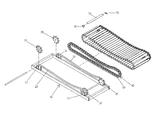
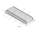
- FIG. 1 is a perspective view of a treadmill in accordance with the preferred embodiment of the present invention.
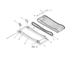
- FIG. 2 is an exploded perspective view of the treadmill in accordance with the preferred embodiment of the present invention.
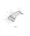
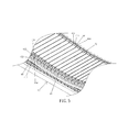
- FIG. 3 is a locally enlarged view of the treadmill as shown in FIG. 1 .
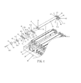
- FIG. 4 is an exploded perspective view of the treadmill as shown in FIG. 3 .
- FIG. 5 is a locally enlarged view of the treadmill as shown in FIG. 1 .
- FIG. 6 is a perspective view of a treadmill in accordance with another preferred embodiment of the present invention.
- a treadmill in accordance with the preferred embodiment of the present invention comprises a frame 10 having two sides each provided with two sprockets 30 , two slide rails 20 mounted on the two sides of the frame 10 , two chains 40 engaging with the two sprockets 30 at the two sides of the frame 10 respectively and corresponding to the two slide rails 20 respectively, a plurality of elongate board 70 mounted between the two chains 40 , and a plurality of rollers 60 mounted on each of the two chains 40 .
- the two arcuate slide rails 20 are parallel with each other. Each of the two slide rails 20 has an arcuate shape. Each of the two sprockets 30 at the two sides of the frame 10 is mounted on and supported by a pivot ear 11 which is secured on the frame 10 .
- the two chains 40 are mounted around the two sprockets 30 at the two sides of the frame 10 respectively. Each of the two chains 40 has an endless shape.
- Each of the elongate board 70 has two ends each provided with a connecting member 50 connected with one of the two chains 40 . Preferably, each of the elongate board 70 has a surface provided with a plurality of nonslip lines to provide an antiskid effect.
- the rollers 60 on each of the two chains 40 rest on one of the two slide rails 20 . When the two chains 40 are rotated, the rollers 60 on each of the two chains 40 slide on one of the two slide rails 20 .
- Each of the two chains 40 includes a plurality of chain sets 41 .
- Each of the chain sets 41 includes two first inner plates 412 mounted on the respective connecting member 50 of one of the elongate board 70 , two second inner plates 411 spaced from the two first inner plates 412 , two reinforcing spacers 413 and 414 each mounted between one of the two first inner plates 412 and one of the two second inner plates 411 , an outer plate 417 linking the two second inner plates 411 , and two shafts 415 and 416 each extending through the outer plate 417 , one of the two second inner plates 411 , one of the two reinforcing spacers 413 and 414 , one of the two first inner plates 412 and the respective connecting member 50 of one of the elongate board 70 , to combine the outer plate 417 , the two second inner plates 411 , the two reinforcing spacers 413 and 414 , the two first inner plates 412 and the respective connecting member 50 of one of the elongate board 70
- the two second inner plates 411 and the two first inner plates 412 are parallel with each other.
- Each of the outer plate 417 , the two second inner plates 411 , the two reinforcing spacers 413 and 414 and the two first inner plates 412 is provided with at least one shaft hole 42 allowing passage of the two shafts 415 and 416 .
- the connecting member 50 of each of the elongate board 70 is substantially L-shaped and has a side provided with two through holes 52 allowing passage of the two shafts 415 and 416 of one of the chain sets 41 .
- the connecting member 50 is connected with each of the elongate board 70 by riveting or screwing.
- Each of the rollers 60 is mounted on one of the two shafts 415 and 416 and rests on the outer plate 417 of one of the chain sets 41 .
- Each of the rollers 60 has a pivot hole 61 mounted on one of the two shafts 415 and 416 of one of the chain sets 41 .
- each of the two slide rails 20 is located at a horizontal linear state.
- the two chains 40 engage with the two sprockets 30 at the two sides of the frame 10 respectively, while the rollers 60 are mounted on each of the two chains 40 and slide on one of the two slide rails 20 , so that the treadmill has a track-type walking belt that has rotation and transmission of high precision and stability.
- each of the two chains 40 has a stabilized structure and is not worn out easily during a long-term utilization, thereby enhancing the lifetime of the treadmill, and thereby reducing the cost of maintenance.
- the sprockets 30 are manufactured by stamping easily and simply, without needing a lathe working of a high price, thereby greatly decreasing the cost of fabrication.
Landscapes
- Health & Medical Sciences (AREA)
- Cardiology (AREA)
- Vascular Medicine (AREA)
- General Health & Medical Sciences (AREA)
- Physical Education & Sports Medicine (AREA)
- Rehabilitation Tools (AREA)
Abstract
Description
Claims (10)
Priority Applications (1)
| Application Number | Priority Date | Filing Date | Title |
|---|---|---|---|
| US15/784,244 US10220249B1 (en) | 2017-10-16 | 2017-10-16 | Treadmill with a track-type walking belt |
Applications Claiming Priority (1)
| Application Number | Priority Date | Filing Date | Title |
|---|---|---|---|
| US15/784,244 US10220249B1 (en) | 2017-10-16 | 2017-10-16 | Treadmill with a track-type walking belt |
Publications (1)
| Publication Number | Publication Date |
|---|---|
| US10220249B1 true US10220249B1 (en) | 2019-03-05 |
Family
ID=65495808
Family Applications (1)
| Application Number | Title | Priority Date | Filing Date |
|---|---|---|---|
| US15/784,244 Expired - Fee Related US10220249B1 (en) | 2017-10-16 | 2017-10-16 | Treadmill with a track-type walking belt |
Country Status (1)
| Country | Link |
|---|---|
| US (1) | US10220249B1 (en) |
Cited By (5)
| Publication number | Priority date | Publication date | Assignee | Title |
|---|---|---|---|---|
| US20190314674A1 (en) * | 2018-04-13 | 2019-10-17 | Yi-Tzu Chen | Treadmill |
| CN110395540A (en) * | 2019-07-29 | 2019-11-01 | 瑞安市智造科技有限公司 | A kind of chain-type material collecting device of Printing Chamber |
| CN110451169A (en) * | 2019-08-14 | 2019-11-15 | 无锡雪浪环境科技股份有限公司 | A kind of hopper anti-rock structure |
| US20220194712A1 (en) * | 2019-05-29 | 2022-06-23 | Laitram, L.L.C. | Modular slat conveyor belt |
| US20240058645A1 (en) * | 2022-08-22 | 2024-02-22 | Tung Keng Enterprise Co., Ltd. | Treadmill |
Citations (9)
| Publication number | Priority date | Publication date | Assignee | Title |
|---|---|---|---|---|
| US4205628A (en) * | 1978-10-24 | 1980-06-03 | Null Robert L | Animal conditioner |
| US4361115A (en) * | 1980-11-17 | 1982-11-30 | Pike Wendell A | Horse exerciser |
| US4687195A (en) * | 1984-02-06 | 1987-08-18 | Tri-Tech, Inc. | Treadmill exerciser |
| US6042514A (en) * | 1998-05-30 | 2000-03-28 | Abelbeck; Kevin G. | Moving surface exercise device |
| US7510511B2 (en) * | 2005-07-11 | 2009-03-31 | Von Detten Volker | Exercise treadmill having a simulated cobblestone running surface |
| US7780573B1 (en) * | 2006-01-31 | 2010-08-24 | Carmein David E E | Omni-directional treadmill with applications |
| US7976437B1 (en) * | 2010-04-30 | 2011-07-12 | Von Detten Volker | Exercise treadmill having a simulated cobblestone running surface |
| US8734301B2 (en) * | 2011-01-06 | 2014-05-27 | Jebb G. Remelius | Particulate material treadmill |
| US9833657B2 (en) * | 2015-03-10 | 2017-12-05 | Christopher Wagner | Stationary manual exercise sled |
-
2017
- 2017-10-16 US US15/784,244 patent/US10220249B1/en not_active Expired - Fee Related
Patent Citations (9)
| Publication number | Priority date | Publication date | Assignee | Title |
|---|---|---|---|---|
| US4205628A (en) * | 1978-10-24 | 1980-06-03 | Null Robert L | Animal conditioner |
| US4361115A (en) * | 1980-11-17 | 1982-11-30 | Pike Wendell A | Horse exerciser |
| US4687195A (en) * | 1984-02-06 | 1987-08-18 | Tri-Tech, Inc. | Treadmill exerciser |
| US6042514A (en) * | 1998-05-30 | 2000-03-28 | Abelbeck; Kevin G. | Moving surface exercise device |
| US7510511B2 (en) * | 2005-07-11 | 2009-03-31 | Von Detten Volker | Exercise treadmill having a simulated cobblestone running surface |
| US7780573B1 (en) * | 2006-01-31 | 2010-08-24 | Carmein David E E | Omni-directional treadmill with applications |
| US7976437B1 (en) * | 2010-04-30 | 2011-07-12 | Von Detten Volker | Exercise treadmill having a simulated cobblestone running surface |
| US8734301B2 (en) * | 2011-01-06 | 2014-05-27 | Jebb G. Remelius | Particulate material treadmill |
| US9833657B2 (en) * | 2015-03-10 | 2017-12-05 | Christopher Wagner | Stationary manual exercise sled |
Cited By (8)
| Publication number | Priority date | Publication date | Assignee | Title |
|---|---|---|---|---|
| US20190314674A1 (en) * | 2018-04-13 | 2019-10-17 | Yi-Tzu Chen | Treadmill |
| US10632339B2 (en) * | 2018-04-13 | 2020-04-28 | Yi-Tzu Chen | Treadmill |
| US20220194712A1 (en) * | 2019-05-29 | 2022-06-23 | Laitram, L.L.C. | Modular slat conveyor belt |
| US11724884B2 (en) * | 2019-05-29 | 2023-08-15 | Laitram, L.L.C. | Modular slat conveyor belt |
| CN110395540A (en) * | 2019-07-29 | 2019-11-01 | 瑞安市智造科技有限公司 | A kind of chain-type material collecting device of Printing Chamber |
| CN110451169A (en) * | 2019-08-14 | 2019-11-15 | 无锡雪浪环境科技股份有限公司 | A kind of hopper anti-rock structure |
| CN110451169B (en) * | 2019-08-14 | 2024-01-19 | 无锡雪浪环境科技股份有限公司 | Anti-shaking structure for hopper |
| US20240058645A1 (en) * | 2022-08-22 | 2024-02-22 | Tung Keng Enterprise Co., Ltd. | Treadmill |
Similar Documents
| Publication | Publication Date | Title |
|---|---|---|
| US10220249B1 (en) | Treadmill with a track-type walking belt | |
| US8801582B2 (en) | Treadmill | |
| US9227816B2 (en) | Vertical support structure and lifting device having the same | |
| US20030185470A1 (en) | Linear motion guide device having two offset ball rows | |
| TWI262886B (en) | Bicycle drive chain | |
| US5441458A (en) | Grooved roller chain idler | |
| US20190105531A1 (en) | Treadmill | |
| US20180201341A1 (en) | Chain | |
| JP6190743B2 (en) | Link plate chain for continuously variable transmission | |
| US6443795B1 (en) | Transmission chain for toys | |
| US20070034488A1 (en) | Roller-type conveying machine | |
| US20200009418A1 (en) | Caterpillar treadmill | |
| US1582516A (en) | Belt tightener and guide | |
| US20070026986A1 (en) | Tensioning device | |
| WO2015146753A1 (en) | Running device | |
| PH12020050382A1 (en) | Manufacturing method of body frame | |
| US10173098B1 (en) | Treadmill with arcuate walking board | |
| PL2042450T3 (en) | Transport device in a profile coating machine | |
| US8973737B2 (en) | Conveying apparatus | |
| JP5975139B1 (en) | Profile plate chain | |
| TW201912211A (en) | Continuous track type belt structure of treadmill capable of reducing friction, noise, maintenance cost, and production cost | |
| CN105947549A (en) | Conveying device | |
| CN101586621A (en) | Spherical roller bearing with wide outer ring | |
| TWI648197B (en) | Tensioning device for chain | |
| FR2875143B1 (en) | SKATE WHEEL WITH RECYCLABLE HUB WITH BALL BEARING |
Legal Events
| Date | Code | Title | Description |
|---|---|---|---|
| FEPP | Fee payment procedure |
Free format text: ENTITY STATUS SET TO UNDISCOUNTED (ORIGINAL EVENT CODE: BIG.); ENTITY STATUS OF PATENT OWNER: SMALL ENTITY |
|
| FEPP | Fee payment procedure |
Free format text: ENTITY STATUS SET TO SMALL (ORIGINAL EVENT CODE: SMAL); ENTITY STATUS OF PATENT OWNER: SMALL ENTITY |
|
| STCF | Information on status: patent grant |
Free format text: PATENTED CASE |
|
| FEPP | Fee payment procedure |
Free format text: MAINTENANCE FEE REMINDER MAILED (ORIGINAL EVENT CODE: REM.); ENTITY STATUS OF PATENT OWNER: SMALL ENTITY |
|
| LAPS | Lapse for failure to pay maintenance fees |
Free format text: PATENT EXPIRED FOR FAILURE TO PAY MAINTENANCE FEES (ORIGINAL EVENT CODE: EXP.); ENTITY STATUS OF PATENT OWNER: SMALL ENTITY |
|
| STCH | Information on status: patent discontinuation |
Free format text: PATENT EXPIRED DUE TO NONPAYMENT OF MAINTENANCE FEES UNDER 37 CFR 1.362 |
|
| FP | Lapsed due to failure to pay maintenance fee |
Effective date: 20230305 |