US10212337B2 - Camera augmented reality based activity history tracking - Google Patents
Camera augmented reality based activity history tracking Download PDFInfo
- Publication number
- US10212337B2 US10212337B2 US15/289,698 US201615289698A US10212337B2 US 10212337 B2 US10212337 B2 US 10212337B2 US 201615289698 A US201615289698 A US 201615289698A US 10212337 B2 US10212337 B2 US 10212337B2
- Authority
- US
- United States
- Prior art keywords
- camera
- digital image
- orientation
- user
- location
- Prior art date
- Legal status (The legal status is an assumption and is not a legal conclusion. Google has not performed a legal analysis and makes no representation as to the accuracy of the status listed.)
- Active
Links
Images


Classifications
-
- H04N5/23222—
-
- H—ELECTRICITY
- H04—ELECTRIC COMMUNICATION TECHNIQUE
- H04N—PICTORIAL COMMUNICATION, e.g. TELEVISION
- H04N1/00—Scanning, transmission or reproduction of documents or the like, e.g. facsimile transmission; Details thereof
- H04N1/00127—Connection or combination of a still picture apparatus with another apparatus, e.g. for storage, processing or transmission of still picture signals or of information associated with a still picture
- H04N1/00132—Connection or combination of a still picture apparatus with another apparatus, e.g. for storage, processing or transmission of still picture signals or of information associated with a still picture in a digital photofinishing system, i.e. a system where digital photographic images undergo typical photofinishing processing, e.g. printing ordering
- H04N1/00183—Photography assistance, e.g. displaying suggestions to the user
-
- H—ELECTRICITY
- H04—ELECTRIC COMMUNICATION TECHNIQUE
- H04N—PICTORIAL COMMUNICATION, e.g. TELEVISION
- H04N23/00—Cameras or camera modules comprising electronic image sensors; Control thereof
- H04N23/60—Control of cameras or camera modules
- H04N23/63—Control of cameras or camera modules by using electronic viewfinders
- H04N23/633—Control of cameras or camera modules by using electronic viewfinders for displaying additional information relating to control or operation of the camera
- H04N23/635—Region indicators; Field of view indicators
-
- H—ELECTRICITY
- H04—ELECTRIC COMMUNICATION TECHNIQUE
- H04N—PICTORIAL COMMUNICATION, e.g. TELEVISION
- H04N23/00—Cameras or camera modules comprising electronic image sensors; Control thereof
- H04N23/60—Control of cameras or camera modules
- H04N23/64—Computer-aided capture of images, e.g. transfer from script file into camera, check of taken image quality, advice or proposal for image composition or decision on when to take image
-
- H04N5/23293—
-
- G—PHYSICS
- G06—COMPUTING; CALCULATING OR COUNTING
- G06F—ELECTRIC DIGITAL DATA PROCESSING
- G06F16/00—Information retrieval; Database structures therefor; File system structures therefor
- G06F16/20—Information retrieval; Database structures therefor; File system structures therefor of structured data, e.g. relational data
- G06F16/29—Geographical information databases
-
- G06F17/30241—
Definitions
- the present invention relates to a system and method for visual media systems, and, in particular embodiments, to techniques for camera augmented reality based activity history tracking.
- Various factors and/or settings can influence image quality when taking pictures or videos with modern digital cameras. Indeed, some features and settings may be adjusted by the user to enhance image quality. For instance, exposure related parameters (e.g., aperture, shutter speed, ISO speed, etc.) may be optimized for various lighting conditions. Further, a camera position can be shifted to improve image quality, as may be the case when a shadow or glare produces an image artifact. Novice users may lack the advanced knowledge/skill required to effectively manipulate camera settings and/or camera positioning to achieve optimal image quality. Accordingly, mechanisms for directing users to adjust camera settings and/or camera positioning are desired.
- exposure related parameters e.g., aperture, shutter speed, ISO speed, etc.
- a camera position can be shifted to improve image quality, as may be the case when a shadow or glare produces an image artifact.
- Novice users may lack the advanced knowledge/skill required to effectively manipulate camera settings and/or camera positioning to achieve optimal image quality. Accordingly, mechanisms for directing users to adjust camera settings and/or camera
- a method for operating a camera comprises taking a picture with a camera to capture a first digital image, and detecting a position of the camera when capturing the first digital image.
- the position of the camera is associated with the first digital image in a histogram file.
- the method further includes monitoring an active position of the camera after capturing the first digital image, and displaying the first digital image on a viewfinder of the camera when the active position of the camera is within a threshold of the position specified by the histogram file.
- An apparatus for performing this method is also provided.
- a method for correcting image quality in digital photography comprises taking a picture using a camera to obtain a first digital image, detecting an image quality problem in the first digital image, determining that the image quality problem is at least partially attributable to a configuration of the camera, instructing the user to reconfigure the camera via augmented reality, and re-taking the picture following re-configuration of the camera to obtain a second digital image.
- the image quality problem is at least partially corrected in the second digital image.
- An apparatus for performing this method is also provided.
- FIG. 1 illustrates a block diagram of a camera
- FIG. 2 illustrates a graph of a three dimensional map of camera activity
- FIG. 3 illustrates a diagram of an activity history map
- FIGS. 4A-4E illustrate diagrams of embodiment viewfinder images used to guide a user to re-align a camera prior to re-taking a picture
- FIG. 5 illustrates a flowchart of an embodiment method for using augmented reality to display a transparent version of a digital image on a viewfinder of a camera as the camera is returned to a position from which the digital image was captured;
- FIG. 6 illustrates a diagram of another embodiment viewfinder image used to guide a user to re-align a camera prior to re-taking a picture via augmented reality;
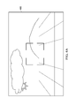
- FIG. 7 illustrates a diagram of yet another embodiment viewfinder image used to guide a user to correct an image quality issue via augmented reality
- FIG. 8 illustrates a flowchart of an embodiment method for correcting image quality problems via augmented reality
- FIG. 9 illustrates a diagram of an embodiment viewfinder image of a histogram file that associates a sequence of locations with a sequence of digital images
- FIG. 10 illustrates a diagram of yet another embodiment viewfinder image that allows a user to cycle through a sequence of digital images
- FIG. 11 illustrates a flowchart of an embodiment method for displaying digital images as a user re-traces locations in which those digital images were previously captured.
- FIG. 12 illustrates an embodiment of a block diagram of a processing system that may be used for implementing the devices and methods disclosed herein.
- aspects of this disclosure use augmented reality to display previously captured images on a viewfinder of a camera as the camera's active position nears a position from which the picture was originally taken.
- positional information e.g., coordinates, etc.
- the positional information may include a spatial location of the camera (e.g., GPS coordinates, etc.) as well as an orientation of the camera (e.g., yaw, pitch, roll, etc.).
- an orientation of the camera e.g., yaw, pitch, roll, etc.
- augmented reality is used to guide the user to configure/re-configure the camera in order to correct (or avoid) an image quality issue/defect when taking/re-taking a picture.
- an indication may be displayed on the viewfinder of the camera that instructs the user re-configure the camera.
- the indication may instruct the user to re-align the camera, to adjust a camera setting (e.g., to change aperture/shutter setting, etc.), or to take the picture under different lighting conditions.
- FIG. 1 illustrates a camera 100 comprising a user interface 110 , an optical instrument module 120 , and a sensors module 130 .
- the user interface 110 includes a viewfinder 112 and an input module 114 .
- the viewfinder 112 may be any component that allows the user to view a picture scene when composing a picture.
- the viewfinder 112 may be an LCD display on a camera phone.
- the input module 114 may be any component that allows the user to manipulate the camera 100 , such as a key pad or touchscreen.
- the optical instrument module 120 may include any collection of components used to capture, process, and store a digital image.
- the optical instrument module 120 may include a central processing unit (CPU) 122 , a memory 124 , a graphics processing unite (GPU) 126 , a camera subsystem 128 , and a sensors subsystem 130 .
- the CPU 122 may be any component capable of performing computations and/or other processing related tasks
- the memory 124 may be any component capable of storing programming and/or instructions for the CPU 122 .
- the GPU 126 may be any component or collection of components configured to create an image in a memory buffer for output to a display, e.g., the viewfinder 112 , etc.
- the camera subsystem 128 may include any component or collection of components used to capture a digital image, e.g., electronic sensor, shutter, etc.
- the sensors module 130 may include any component or collection of components used to detect or monitor a camera position (e.g., location, orientation, etc.) or environmental condition (e.g., lighting, etc.).
- the sensor module 130 may include a gyroscope and/or accelerometer for detecting an orientation (e.g., yaw, pitch, roll, etc.) of the camera 100 , a global positioning system (GPS) for detecting a spatial location of the camera 100 , and a metering system (e.g., ambient light sensor) for detecting environmental/lighting information.
- GPS global positioning system
- the GPS may be a micro or indoor GPS capable of providing precise camera location, e.g., three dimensional coordinate information.
- FIG. 2 illustrates a graph depicting a position of a camera 280 .
- the camera 280 has a spatial location (x, y, z) as well as a spatial orientation (roll, yaw, and pitch).
- roll, yaw, and pitch are used loosely in this disclosure, and may correspond to elemental rotations, e.g., Euler angles ( ⁇ , ⁇ , ⁇ ) about axes of a fixed or rotating coordinate system.
- camera positions are associated with digital images in an activity history map stored in a histogram file.
- FIG. 3 Illustrates an activity history map 300 associating sequence of digital images 301 - 308 with vectors along a coordinate plane.
- each vector represents the spatial location (e.g., x, y, z) of the camera when the corresponding digital image was captured, while the arrow head represents the orientation of the camera when the corresponding digital image was captured.
- the digital images 303 - 305 were captured in the same (or similar) spatial location, but at different camera orientations.
- FIGS. 4A-4E illustrate how digital images 410 - 460 are displayed on a viewfinder 400 of a camera using augmented reality.
- FIG. 4A illustrates a viewfinder 400 of the camera before any images are displayed.
- FIG. 4B illustrates how a transparent version of a digital image 410 is displayed on the viewfinder 400 as an active position of the camera nears a position associated with the digital image 410 in a histogram file.
- FIG. 4C illustrates how a transparent version of a digital image 420 is displayed on the viewfinder 400 as an orientation of the camera nears a spatial orientation associated with the digital image 420 .
- the camera may include components (e.g., micro GPS, etc.) that are capable of detecting the location and/or orientation of the camera with high precision.
- the transparent version of the digital images 410 , 420 may move gradually over the viewfinder 400 as the active position of the camera changes in relation to the position stored in the histogram file. For example, a difference or shift (e.g., ⁇ y, ⁇ x) between the digital image 410 and a live picture/scene displayed on the viewfinder 400 may decrease as the active location of the camera approaches the location stored in the histogram file. As another example, an angular difference (e.g., ⁇ ) between the digital image 420 and a live picture/scene displayed on the viewfinder 400 may decrease as the active orientation of the camera approaches the orientation associated with the digital image 420 in the histogram file.
- transparent versions of multiple digital images may be displayed on the viewfinder if the digital images were captured in relatively close proximity to one another.
- FIG. 4D illustrates how transparent versions of digital images 430 , 440 are displayed on the viewfinder 400 as a position of the camera nears positions associated with the digital images 430 , 440 .
- FIG. 4E illustrates how transparent versions of digital images 450 , 460 are displayed on the viewfinder 400 as a position of the camera nears positions associated with the digital images 450 , 460
- FIG. 5 illustrates a method 500 for using augmented reality to display a transparent version of a digital image on a viewfinder of a camera as the camera's position nears a position associated with the digital image.
- the method 500 begins with step 510 , where the camera takes a picture to capture a digital image.
- the method 500 proceeds to step 520 , where a sensory module detects a position of the camera when capturing the digital image.
- the method 500 proceeds to step 530 , where the detected camera position is associated with the digital image in a histogram file.
- the method 500 proceeds to step 540 , where an active position of the camera is monitored.
- step 550 it is detected that the active position of the camera is within a threshold of the camera position specified by the histogram file.
- step 560 a transparent version of the digital image is displayed on the viewfinder of the camera.
- aspects of this disclosure also use augmented reality to guide a user to re-configure a camera to correct or avoid image detects in a digital images.
- an instruction may be displayed on the viewfinder to reduce the flash or to re-align the camera to avoid a shadow.
- the instructions may be determined in accordance with a quality analysis of a previous picture or image.
- the camera may determine that a defect in a picture (e.g., shadow, etc.) could have been avoided had the camera position been shifted slightly, and thereafter instruct the user to shift the camera when retaking taking the picture.
- a real-time quality analysis may be performed on a picture scene displayed on the viewfinder to avoid the image quality problem before the picture is ever taken.
- FIG. 6 illustrates how augmented reality can be used to guide a user in re-aligning a camera.
- a transparent version of a digital image 610 is displayed on a viewfinder 600 along with indications 620 , 625 that guide the user to re-align a live scene in relation to the digital image 610 .
- the indications 620 , 625 may instruct the user to align the camera to fix an image quality issue in the digital image 610 .
- the indications 620 , 625 may instruct the user to align the camera in accordance with the “rule of thirds” so that a horizon is positioned on or around the bottom third of the photo.
- the rule of thirds is a general image composition principles dictating that a horizon should be aligned at a line bisecting the lower third of the photo from the upper two-thirds.
- Other image composition principles may be used as a basis for re-aligning the camera, such as principles related to headroom guidance, lead room guidance, diagonal rule guidance, the golden ratio and others.
- FIG. 7 illustrates how augmented reality can be used to guide a user in re-configuring a camera.
- a transparent version of a digital image 710 is displayed on a viewfinder 700 along with an indication 715 that the digital image 710 was underexposed.
- the indication 715 could instruct the user to change any camera setting, such as the camera mode information (e.g., M, Av, Tv, P, Auto, Portrait, Macro, Sports, Night, Camera, etc.) aperture/shutter settings, blown out highlights, dominant blacks, and others.
- FIG. 8 illustrates a method 800 for using augmented reality to guide a user to re-configure a camera to fix an image quality problem in a digital image.
- the method 800 begins with step 810 , where the camera takes a picture to obtain a first digital image.
- the method 800 proceeds to step 820 , where an image quality problem is detected in the first digital image.
- the method 800 begins with step 830 , where it is determined that the image quality problem is at least partially attributable to configuration of the camera.
- the method 800 begins with step 840 , where the user is instructed via augmented reality to reconfigure the camera to fix or mitigate the image quality problem.
- the method 800 proceeds to step 850 , where the camera re-takes the picture to obtain a second digital image.
- the activity tracking function may allow a history of images to be displayed via augmented reality. For instance, a user may take a sequence of pictures at a corresponding sequence of locations, and thereafter view the sequence of pictures via the camera's display while re-visiting the sequence of locations.
- the activity tracking history function may include a feature for analyzing the quality of previously taken photos. For instance, history can be dynamically analyzed for photo quality, and the results can be depicted using augmented reality.
- An activity history map may be used to create a 3D model that the user can view using augmented reality.
- the model is mapped to a three dimensional perspective projection that is overlaid onto a viewfinder.
- FIG. 9 illustrates how a 3D model of an activity history map 900 can be overlaid onto a viewfinder.
- the sequence of digital images 910 - 970 are associated with positions on the activity history map.
- a user may use this 3D rendering as a guide when re-positioning the camera to view a previously captured digital image. For example, the user may move from one location to another to view the images in a sequence.
- users may remove the events from the history by swiping the overlay using one or two of their fingers, as shown in FIG. 10 .
- FIG. 11 illustrates a method 1100 for performing an activity tracking function to allow a history of images to be displayed via augmented reality.
- the method 1100 begins at step 1110 , where a camera takes pictures at a sequence of location to obtain a sequence of digital images. Thereafter, the method 1100 proceeds to step 1120 , where the camera detects coordinates for each location in the sequence of locations. The coordinates may relate to spatial locations and orientations of the camera when the sequence of digital images where captured. Subsequently, the method 1100 proceeds to step 1130 , where the camera associates the coordinates with the sequence of digital images in a histogram file.
- step 1140 the camera monitors a position of the camera as the user retraces locations in the sequence of locations.
- step 1150 the camera displays the sequence of digital images on a viewfinder of the camera in accordance with the position of the camera.
- aspects of this disclosure display a sequence of digital images in an activity history map via augmented reality.
- the user may begin by launching the camera viewfinder with no history, and then capturing an image or video.
- the history may begin with the first captured image/video.
- Previously captured images/videos may be overlaid onto viewfinder with transparency as the images are captured.
- the overlays appear sequentially on the viewfinder, with newly captured images/videos being added to the history as well as to the augmented reality experience. For instance, a one finger swipe may remove the item at the top of the stack, while a two finger swipe may remove the entire stack.
- aspects of this disclosure provide a next generation camera user interface, which may make the camera more user-friendly.
- the next generation interface may include an interface for viewing captured history.
- aspects of this disclosure provide merged gallery playback with camera viewfinder experience.
- captured images are displayed immediately in three dimensional space.
- aspects of this disclosure may support panorama and photo stitching without changing camera mode.
- FIG. 12 is a block diagram of a processing system that may be used for implementing the devices and methods disclosed herein. Specific devices may utilize all of the components shown, or only a subset of the components, and levels of integration may vary from device to device. Furthermore, a device may contain multiple instances of a component, such as multiple processing units, processors, memories, transmitters, receivers, etc.
- the processing system may comprise a processing unit equipped with one or more input/output devices, such as a speaker, microphone, mouse, touchscreen, keypad, keyboard, printer, display, and the like.
- the processing unit may include a central processing unit (CPU), memory, a mass storage device, a video adapter, and an I/O interface connected to a bus.
- CPU central processing unit
- the bus may be one or more of any type of several bus architectures including a memory bus or memory controller, a peripheral bus, video bus, or the like.
- the CPU may comprise any type of electronic data processor.
- the memory may comprise any type of system memory such as static random access memory (SRAM), dynamic random access memory (DRAM), synchronous DRAM (SDRAM), read-only memory (ROM), a combination thereof, or the like.
- SRAM static random access memory
- DRAM dynamic random access memory
- SDRAM synchronous DRAM
- ROM read-only memory
- the memory may include ROM for use at boot-up, and DRAM for program and data storage for use while executing programs.
- the mass storage device may comprise any type of storage device configured to store data, programs, and other information and to make the data, programs, and other information accessible via the bus.
- the mass storage device may comprise, for example, one or more of a solid state drive, hard disk drive, a magnetic disk drive, an optical disk drive, or the like.
- the video adapter and the I/O interface provide interfaces to couple external input and output devices to the processing unit.
- input and output devices include the display coupled to the video adapter and the mouse/keyboard/printer coupled to the I/O interface.
- Other devices may be coupled to the processing unit, and additional or fewer interface cards may be utilized.
- a serial interface card (not shown) may be used to provide a serial interface for a printer.
- the processing unit also includes one or more network interfaces, which may comprise wired links, such as an Ethernet cable or the like, and/or wireless links to access nodes or different networks.
- the network interface allows the processing unit to communicate with remote units via the networks.
- the network interface may provide wireless communication via one or more transmitters/transmit antennas and one or more receivers/receive antennas.
- the processing unit is coupled to a local-area network or a wide-area network for data processing and communications with remote devices, such as other processing units, the Internet, remote storage facilities, or the like.
Abstract
Augmented reality can be used to display previously captured images on a viewfinder of a camera as the camera's active position nears a position from which the picture was originally taken. A histogram file may associate the original image with positional information of the camera when the image was captured. When the cameras active position nears those coordinates, a transparent version of the digital image is displayed on the viewfinder of the camera. The positional information may include a spatial location of the camera (e.g., GPS coordinates, etc.) as well as an orientation of the camera (e.g., yaw, pitch, roll, etc.). Augmented reality can be used to guide the user to configure/re-configure the camera in order to correct (or avoid) an image quality issue/defect when re-taking a picture.
Description
This patent application is a continuation of U.S. Non-Provisional application Ser. No. 14/212,157 filed on Mar. 14, 2014 and entitled “Camera Augmented Reality Based Activity History Tracking,” which claims priority to U.S. Provisional Application No. 61/784,667, filed on Mar. 14, 2013 and entitled “Camera Augmented Reality Based Activity History Tracking,” both of which are hereby incorporated by reference herein as if reproduced in their entireties.
The present invention relates to a system and method for visual media systems, and, in particular embodiments, to techniques for camera augmented reality based activity history tracking.
Various factors and/or settings can influence image quality when taking pictures or videos with modern digital cameras. Indeed, some features and settings may be adjusted by the user to enhance image quality. For instance, exposure related parameters (e.g., aperture, shutter speed, ISO speed, etc.) may be optimized for various lighting conditions. Further, a camera position can be shifted to improve image quality, as may be the case when a shadow or glare produces an image artifact. Novice users may lack the advanced knowledge/skill required to effectively manipulate camera settings and/or camera positioning to achieve optimal image quality. Accordingly, mechanisms for directing users to adjust camera settings and/or camera positioning are desired.
Technical advantages are generally achieved, by embodiments of this disclosure which describe techniques for camera augmented reality based activity history tracking.
In accordance with an embodiment, a method for operating a camera is provided. In this example, the method comprises taking a picture with a camera to capture a first digital image, and detecting a position of the camera when capturing the first digital image. The position of the camera is associated with the first digital image in a histogram file. The method further includes monitoring an active position of the camera after capturing the first digital image, and displaying the first digital image on a viewfinder of the camera when the active position of the camera is within a threshold of the position specified by the histogram file. An apparatus for performing this method is also provided.
In accordance with another embodiment, a method for correcting image quality in digital photography is provided. In this example, the method comprises taking a picture using a camera to obtain a first digital image, detecting an image quality problem in the first digital image, determining that the image quality problem is at least partially attributable to a configuration of the camera, instructing the user to reconfigure the camera via augmented reality, and re-taking the picture following re-configuration of the camera to obtain a second digital image. The image quality problem is at least partially corrected in the second digital image. An apparatus for performing this method is also provided.
For a more complete understanding of the present invention, and the advantages thereof, reference is now made to the following descriptions taken in conjunction with the accompanying drawing, in which:
Corresponding numerals and symbols in the different figures generally refer to corresponding parts unless otherwise indicated. The figures are drawn to clearly illustrate the relevant aspects of the embodiments and are not necessarily drawn to scale.
The making and using of the presently preferred embodiments are discussed in detail below. It should be appreciated, however, that the present invention provides many applicable inventive concepts that can be embodied in a wide variety of specific contexts. The specific embodiments discussed are merely illustrative of specific ways to make and use the invention, and do not limit the scope of the invention.
Aspects of this disclosure use augmented reality to display previously captured images on a viewfinder of a camera as the camera's active position nears a position from which the picture was originally taken. In some embodiments, positional information (e.g., coordinates, etc.) of the camera is associated with a digital image in a histogram file, and a transparent version of the digital image is displayed on the viewfinder of the camera when the camera is returned to that position. The positional information may include a spatial location of the camera (e.g., GPS coordinates, etc.) as well as an orientation of the camera (e.g., yaw, pitch, roll, etc.). Hence, pictures captured at the same location (but different angles) may be distinguished from one another based on the camera's orientation. In some embodiments, augmented reality is used to guide the user to configure/re-configure the camera in order to correct (or avoid) an image quality issue/defect when taking/re-taking a picture. For example, an indication may be displayed on the viewfinder of the camera that instructs the user re-configure the camera. The indication may instruct the user to re-align the camera, to adjust a camera setting (e.g., to change aperture/shutter setting, etc.), or to take the picture under different lighting conditions. These and other aspects are described in greater detail below.
Aspects of this disclosure use augmented reality to display a transparent version of a digital image on the viewfinder of the camera when the camera nears a position from which the digital image was previously captured. FIGS. 4A-4E illustrate how digital images 410-460 are displayed on a viewfinder 400 of a camera using augmented reality. FIG. 4A illustrates a viewfinder 400 of the camera before any images are displayed. FIG. 4B illustrates how a transparent version of a digital image 410 is displayed on the viewfinder 400 as an active position of the camera nears a position associated with the digital image 410 in a histogram file. FIG. 4C illustrates how a transparent version of a digital image 420 is displayed on the viewfinder 400 as an orientation of the camera nears a spatial orientation associated with the digital image 420.
In some embodiments, the camera may include components (e.g., micro GPS, etc.) that are capable of detecting the location and/or orientation of the camera with high precision. In those embodiments, the transparent version of the digital images 410, 420 may move gradually over the viewfinder 400 as the active position of the camera changes in relation to the position stored in the histogram file. For example, a difference or shift (e.g., Δy, Δx) between the digital image 410 and a live picture/scene displayed on the viewfinder 400 may decrease as the active location of the camera approaches the location stored in the histogram file. As another example, an angular difference (e.g., Δθ) between the digital image 420 and a live picture/scene displayed on the viewfinder 400 may decrease as the active orientation of the camera approaches the orientation associated with the digital image 420 in the histogram file.
In some embodiments, transparent versions of multiple digital images may be displayed on the viewfinder if the digital images were captured in relatively close proximity to one another. FIG. 4D illustrates how transparent versions of digital images 430, 440 are displayed on the viewfinder 400 as a position of the camera nears positions associated with the digital images 430, 440. As another example, FIG. 4E illustrates how transparent versions of digital images 450, 460 are displayed on the viewfinder 400 as a position of the camera nears positions associated with the digital images 450, 460
Aspects of this disclosure also use augmented reality to guide a user to re-configure a camera to correct or avoid image detects in a digital images. For instance, an instruction may be displayed on the viewfinder to reduce the flash or to re-align the camera to avoid a shadow. In embodiments, the instructions may be determined in accordance with a quality analysis of a previous picture or image. As an example, the camera may determine that a defect in a picture (e.g., shadow, etc.) could have been avoided had the camera position been shifted slightly, and thereafter instruct the user to shift the camera when retaking taking the picture. In other embodiments, a real-time quality analysis may be performed on a picture scene displayed on the viewfinder to avoid the image quality problem before the picture is ever taken.
Additional aspects of this disclosure provide an activity history tracking function. The activity tracking function may allow a history of images to be displayed via augmented reality. For instance, a user may take a sequence of pictures at a corresponding sequence of locations, and thereafter view the sequence of pictures via the camera's display while re-visiting the sequence of locations. The activity tracking history function may include a feature for analyzing the quality of previously taken photos. For instance, history can be dynamically analyzed for photo quality, and the results can be depicted using augmented reality.
An activity history map may be used to create a 3D model that the user can view using augmented reality. The model is mapped to a three dimensional perspective projection that is overlaid onto a viewfinder. FIG. 9 illustrates how a 3D model of an activity history map 900 can be overlaid onto a viewfinder. As shown, the sequence of digital images 910-970 are associated with positions on the activity history map. A user may use this 3D rendering as a guide when re-positioning the camera to view a previously captured digital image. For example, the user may move from one location to another to view the images in a sequence. In an embodiment, users may remove the events from the history by swiping the overlay using one or two of their fingers, as shown in FIG. 10 .
Aspects of this disclosure display a sequence of digital images in an activity history map via augmented reality. In one example, the user may begin by launching the camera viewfinder with no history, and then capturing an image or video. The history may begin with the first captured image/video. Previously captured images/videos may be overlaid onto viewfinder with transparency as the images are captured. As the camera is pointed in different directions, the overlays appear sequentially on the viewfinder, with newly captured images/videos being added to the history as well as to the augmented reality experience. For instance, a one finger swipe may remove the item at the top of the stack, while a two finger swipe may remove the entire stack.
Aspects of this disclosure provide a next generation camera user interface, which may make the camera more user-friendly. The next generation interface may include an interface for viewing captured history. Further, aspects of this disclosure provide merged gallery playback with camera viewfinder experience. In some embodiments, captured images are displayed immediately in three dimensional space. Aspects of this disclosure may support panorama and photo stitching without changing camera mode.
The bus may be one or more of any type of several bus architectures including a memory bus or memory controller, a peripheral bus, video bus, or the like. The CPU may comprise any type of electronic data processor. The memory may comprise any type of system memory such as static random access memory (SRAM), dynamic random access memory (DRAM), synchronous DRAM (SDRAM), read-only memory (ROM), a combination thereof, or the like. In an embodiment, the memory may include ROM for use at boot-up, and DRAM for program and data storage for use while executing programs.
The mass storage device may comprise any type of storage device configured to store data, programs, and other information and to make the data, programs, and other information accessible via the bus. The mass storage device may comprise, for example, one or more of a solid state drive, hard disk drive, a magnetic disk drive, an optical disk drive, or the like.
The video adapter and the I/O interface provide interfaces to couple external input and output devices to the processing unit. As illustrated, examples of input and output devices include the display coupled to the video adapter and the mouse/keyboard/printer coupled to the I/O interface. Other devices may be coupled to the processing unit, and additional or fewer interface cards may be utilized. For example, a serial interface card (not shown) may be used to provide a serial interface for a printer.
The processing unit also includes one or more network interfaces, which may comprise wired links, such as an Ethernet cable or the like, and/or wireless links to access nodes or different networks. The network interface allows the processing unit to communicate with remote units via the networks. For example, the network interface may provide wireless communication via one or more transmitters/transmit antennas and one or more receivers/receive antennas. In an embodiment, the processing unit is coupled to a local-area network or a wide-area network for data processing and communications with remote devices, such as other processing units, the Internet, remote storage facilities, or the like.
While this invention has been described with reference to illustrative embodiments, this description is not intended to be construed in a limiting sense. Various modifications and combinations of the illustrative embodiments, as well as other embodiments of the invention, will be apparent to persons skilled in the art upon reference to the description. It is therefore intended that the appended claims encompass any such modifications or embodiments.
Claims (20)
1. A method for operating a camera, the method comprising:
monitoring an active location and an active orientation of the camera; and
overlaying an at least partially transparent version of a first digital image over a live scene displayed on a viewfinder of the camera upon detecting that the active location of the camera is within a threshold distance of a pre-defined location and the active orientation of the camera is within a threshold angle of a pre-defined orientation.
2. The method of claim 1 , wherein the pre-defined location and pre-defined orientation are associated with the first digital image in a histogram file.
3. The method of claim 1 , wherein the active orientation includes one or a combination of a yaw, pitch, and roll of the camera.
4. The method of claim 1 , wherein the pre-defined location and the pre-defined orientation correspond to a previous location and orientation from which the first digital image was captured.
5. The method of claim 4 , further comprising:
detecting an image quality problem in the first digital image;
instructing a user to re-configure the camera via augmented reality to at least partially correct the image quality problem; and
re-taking a picture associated with the first digital image after the user re-configures the camera to obtain a second digital image, wherein the image quality problem is at least partially corrected in the second digital image.
6. The method of claim 5 , wherein instructing the user to re-configure the camera via augmented reality comprises:
displaying an indication on the viewfinder of the camera, the indication guiding the user to re-align the camera prior to re-taking the picture.
7. The method of claim 5 , wherein instructing the user to re-configure the camera via augmented reality comprises:
displaying an instruction on the viewfinder, the instruction prompting the user to adjust a camera setting prior to re-taking the picture.
8. The method of claim 5 , wherein instructing the user to re-configure the camera via augmented reality comprises:
displaying an instruction on the viewfinder, the instruction prompting the user to re-take the picture under different lighting conditions.
9. The method of claim 1 , further comprising:
instructing a user to reconfigure the camera via augmented reality by displaying instructions to re-align the camera relative to the at least partially transparent version of the first digital image.
10. A computer program product comprising a non-transitory computer readable storage medium storing programming, the programming including instructions to:
monitor an active location and an active orientation of a camera; and
overlay an at least partially transparent version of a first digital image over a live scene displayed on a viewfinder of the camera upon detecting that the active location of the camera is within a threshold distance of a pre-defined location and the active orientation of the camera is within a threshold angle of a pre-defined orientation.
11. The computer program product of claim 10 , wherein the pre-defined location and pre-defined orientation are associated with the first digital image in a histogram file.
12. The computer program product of claim 11 , wherein the active orientation includes one or a combination of a yaw, pitch, and roll of the camera.
13. The computer program product of claim 11 , wherein the pre-defined location and the pre-defined orientation correspond to a previous location and orientation from which the first digital image was captured.
14. The computer program product of claim 13 , wherein the programming further including instructions to:
detect an image quality problem in the first digital image;
instruct a user to re-configure the camera via augmented reality to at least partially correct the image quality problem; and
instruct the user to re-take the picture after the user re-configures the camera to obtain a second digital image, wherein the image quality problem is at least partially corrected in the second digital image.
15. The computer program product of claim 14 , wherein the instructions to instruct the user to re-configure the camera via augmented reality include instructions to:
display an instruction on the viewfinder, the instruction prompting the user to adjust a camera setting prior to re-taking the picture or to re-take the picture under different lighting conditions.
16. The computer program product of claim 10 , wherein the programming further includes instructions to:
instruct a user to reconfigure the camera via augmented reality by displaying instructions to re-align the camera relative to the at least partially transparent version of the first digital image.
17. An electrical apparatus comprising:
a position sensor configured to monitor an active location and an active orientation of a camera; and
an electronic viewfinder configured to overlay an at least partially transparent version of a first digital image over a live scene displayed on a viewfinder of the camera upon detecting that the active location of the camera is within a threshold of a pre-defined location and the active orientation of the camera is within a threshold angle of a pre-defined orientation.
18. The electrical apparatus of claim 17 , wherein the pre-defined location and pre-defined orientation are associated with the first digital image in a histogram file.
19. The electrical apparatus of claim 17 , wherein the active orientation includes one or a combination of a yaw, pitch, and roll of the camera.
20. The electrical apparatus of claim 17 , wherein the pre-defined location and the pre-defined orientation correspond to a previous location and orientation from which the first digital image was captured.
Priority Applications (2)
| Application Number | Priority Date | Filing Date | Title |
|---|---|---|---|
| US15/289,698 US10212337B2 (en) | 2013-03-14 | 2016-10-10 | Camera augmented reality based activity history tracking |
| US15/689,397 US10129462B2 (en) | 2013-03-14 | 2017-08-29 | Camera augmented reality based activity history tracking |
Applications Claiming Priority (3)
| Application Number | Priority Date | Filing Date | Title |
|---|---|---|---|
| US201361784667P | 2013-03-14 | 2013-03-14 | |
| US14/212,157 US9503634B2 (en) | 2013-03-14 | 2014-03-14 | Camera augmented reality based activity history tracking |
| US15/289,698 US10212337B2 (en) | 2013-03-14 | 2016-10-10 | Camera augmented reality based activity history tracking |
Related Parent Applications (1)
| Application Number | Title | Priority Date | Filing Date |
|---|---|---|---|
| US14/212,157 Continuation US9503634B2 (en) | 2013-03-14 | 2014-03-14 | Camera augmented reality based activity history tracking |
Related Child Applications (1)
| Application Number | Title | Priority Date | Filing Date |
|---|---|---|---|
| US15/689,397 Continuation US10129462B2 (en) | 2013-03-14 | 2017-08-29 | Camera augmented reality based activity history tracking |
Publications (2)
| Publication Number | Publication Date |
|---|---|
| US20170034433A1 US20170034433A1 (en) | 2017-02-02 |
| US10212337B2 true US10212337B2 (en) | 2019-02-19 |
Family
ID=51525747
Family Applications (3)
| Application Number | Title | Priority Date | Filing Date |
|---|---|---|---|
| US14/212,157 Active US9503634B2 (en) | 2013-03-14 | 2014-03-14 | Camera augmented reality based activity history tracking |
| US15/289,698 Active US10212337B2 (en) | 2013-03-14 | 2016-10-10 | Camera augmented reality based activity history tracking |
| US15/689,397 Active US10129462B2 (en) | 2013-03-14 | 2017-08-29 | Camera augmented reality based activity history tracking |
Family Applications Before (1)
| Application Number | Title | Priority Date | Filing Date |
|---|---|---|---|
| US14/212,157 Active US9503634B2 (en) | 2013-03-14 | 2014-03-14 | Camera augmented reality based activity history tracking |
Family Applications After (1)
| Application Number | Title | Priority Date | Filing Date |
|---|---|---|---|
| US15/689,397 Active US10129462B2 (en) | 2013-03-14 | 2017-08-29 | Camera augmented reality based activity history tracking |
Country Status (1)
| Country | Link |
|---|---|
| US (3) | US9503634B2 (en) |
Families Citing this family (51)
| Publication number | Priority date | Publication date | Assignee | Title |
|---|---|---|---|---|
| US9854209B2 (en) | 2011-04-19 | 2017-12-26 | Ford Global Technologies, Llc | Display system utilizing vehicle and trailer dynamics |
| US9708000B2 (en) | 2011-04-19 | 2017-07-18 | Ford Global Technologies, Llc | Trajectory planner for a trailer backup assist system |
| US9500497B2 (en) | 2011-04-19 | 2016-11-22 | Ford Global Technologies, Llc | System and method of inputting an intended backing path |
| US8909426B2 (en) | 2011-04-19 | 2014-12-09 | Ford Global Technologies | Trailer path curvature control for trailer backup assist |
| US8972109B2 (en) | 2011-04-19 | 2015-03-03 | Ford Global Technologies | Rotatable driver interface for trailer backup assist |
| US9290203B2 (en) | 2011-04-19 | 2016-03-22 | Ford Global Technologies, Llc | Trailer length estimation in hitch angle applications |
| US9238483B2 (en) | 2011-04-19 | 2016-01-19 | Ford Global Technologies, Llc | Trailer backup assist system with trajectory planner for multiple waypoints |
| US9517794B2 (en) | 2011-04-19 | 2016-12-13 | Ford Global Technologies, Llc | Offset compensation for trailer backup assist steering input device |
| US9505434B2 (en) | 2011-04-19 | 2016-11-29 | Ford Global Technologies, Llc | Trailer backup assist system with normalized steering input device for different trailers |
| US9555832B2 (en) | 2011-04-19 | 2017-01-31 | Ford Global Technologies, Llc | Display system utilizing vehicle and trailer dynamics |
| US9493187B2 (en) | 2011-04-19 | 2016-11-15 | Ford Global Technologies, Llc | Control for trailer backup assist system |
| US9290204B2 (en) | 2011-04-19 | 2016-03-22 | Ford Global Technologies, Llc | Hitch angle monitoring system and method |
| US9374562B2 (en) | 2011-04-19 | 2016-06-21 | Ford Global Technologies, Llc | System and method for calculating a horizontal camera to target distance |
| US9290202B2 (en) | 2011-04-19 | 2016-03-22 | Ford Global Technologies, Llc | System and method of calibrating a trailer backup assist system |
| US9434414B2 (en) | 2011-04-19 | 2016-09-06 | Ford Global Technologies, Llc | System and method for determining a hitch angle offset |
| US9937953B2 (en) | 2011-04-19 | 2018-04-10 | Ford Global Technologies, Llc | Trailer backup offset determination |
| US9335163B2 (en) | 2011-04-19 | 2016-05-10 | Ford Global Technologies, Llc | Trailer length estimation in hitch angle applications |
| US9513103B2 (en) | 2011-04-19 | 2016-12-06 | Ford Global Technologies, Llc | Hitch angle sensor assembly |
| US9373044B2 (en) | 2011-07-25 | 2016-06-21 | Ford Global Technologies, Llc | Trailer lane departure warning system |
| US9511799B2 (en) | 2013-02-04 | 2016-12-06 | Ford Global Technologies, Llc | Object avoidance for a trailer backup assist system |
| US9592851B2 (en) | 2013-02-04 | 2017-03-14 | Ford Global Technologies, Llc | Control modes for a trailer backup assist system |
| US20150098000A1 (en) * | 2013-10-03 | 2015-04-09 | Futurewei Technologies, Inc. | System and Method for Dynamic Image Composition Guidance in Digital Camera |
| US9623904B2 (en) | 2014-06-03 | 2017-04-18 | Ford Global Technologies, Llc | Trailer curvature control with adaptive trailer length estimation |
| US9540043B2 (en) | 2014-07-30 | 2017-01-10 | Ford Global Technologies, Llc | Trailer backup assist system with active trailer braking for curvature control |
| US9340228B2 (en) | 2014-10-13 | 2016-05-17 | Ford Global Technologies, Llc | Trailer motion and parameter estimation system |
| US9315212B1 (en) | 2014-10-13 | 2016-04-19 | Ford Global Technologies, Llc | Trailer sensor module and associated method of wireless trailer identification and motion estimation |
| US9533683B2 (en) | 2014-12-05 | 2017-01-03 | Ford Global Technologies, Llc | Sensor failure mitigation system and mode management |
| US9522677B2 (en) | 2014-12-05 | 2016-12-20 | Ford Global Technologies, Llc | Mitigation of input device failure and mode management |
| US9522699B2 (en) | 2015-02-05 | 2016-12-20 | Ford Global Technologies, Llc | Trailer backup assist system with adaptive steering angle limits |
| US10286950B2 (en) | 2015-02-10 | 2019-05-14 | Ford Global Technologies, Llc | Speed optimized trajectory control for motor vehicles |
| US9616923B2 (en) | 2015-03-03 | 2017-04-11 | Ford Global Technologies, Llc | Topographical integration for trailer backup assist system |
| US9623859B2 (en) | 2015-04-03 | 2017-04-18 | Ford Global Technologies, Llc | Trailer curvature control and mode management with powertrain and brake support |
| US9744972B2 (en) | 2015-04-09 | 2017-08-29 | Ford Global Technologies, Llc | Trailer backup aid speed limiting via braking |
| US9676377B2 (en) | 2015-06-17 | 2017-06-13 | Ford Global Technologies, Llc | Speed limiting comfort enhancement |
| US9896126B2 (en) | 2015-07-08 | 2018-02-20 | Ford Global Technologies, Llc | Jackknife detection for vehicle reversing a trailer |
| US10023229B2 (en) | 2015-07-30 | 2018-07-17 | Ford Global Technologies, Llc | Multi-mode trailer backup assist interface knob |
| US9714051B2 (en) | 2015-09-21 | 2017-07-25 | Ford Global Technologies, Llc | Parking feature multi-function tilt knob |
| US10104282B2 (en) * | 2015-09-30 | 2018-10-16 | Ricoh Co., Ltd. | Yaw user interface |
| US10144452B2 (en) | 2015-10-08 | 2018-12-04 | Ford Global Technologies, Llc | Active adaptive haptic multi-function knob |
| US9981662B2 (en) | 2015-10-15 | 2018-05-29 | Ford Global Technologies, Llc | Speed limiting comfort enhancement |
| US10536628B2 (en) * | 2015-10-23 | 2020-01-14 | Telefonaktiebolaget Lm Ericsson (Publ) | Providing camera settings from at least one image/video hosting service |
| US9840278B2 (en) | 2015-10-27 | 2017-12-12 | Ford Global Technologies, Llc | Illuminated vehicle control management pushbutton knob |
| TWI581631B (en) * | 2015-11-12 | 2017-05-01 | 群邁通訊股份有限公司 | An Assisting Method for Taking Pictures and An Electronic Device |
| US9895945B2 (en) | 2015-12-08 | 2018-02-20 | Ford Global Technologies, Llc | Trailer backup assist system with hitch assist |
| US10482663B2 (en) * | 2016-03-29 | 2019-11-19 | Microsoft Technology Licensing, Llc | Virtual cues for augmented-reality pose alignment |
| US11493988B2 (en) | 2016-04-29 | 2022-11-08 | Hewlett-Packard Development Company, L.P. | Guidance information relating to a target image |
| CN108989654A (en) * | 2017-06-05 | 2018-12-11 | 中兴通讯股份有限公司 | Shoot guidance method, device and computer readable storage medium |
| US20200342610A1 (en) * | 2019-04-24 | 2020-10-29 | XRSpace CO., LTD. | Method of Pose Change Notification and Related Interactive Image Processing System |
| CN113727012B (en) * | 2020-08-27 | 2022-09-27 | 荣耀终端有限公司 | Shooting method and terminal |
| CN112312111A (en) * | 2020-10-30 | 2021-02-02 | 北京字节跳动网络技术有限公司 | Virtual image display method and device, electronic equipment and storage medium |
| US20240089590A1 (en) * | 2022-09-14 | 2024-03-14 | Lenovo (Singapore) Pte. Ltd. | Production value of a video stream |
Citations (15)
| Publication number | Priority date | Publication date | Assignee | Title |
|---|---|---|---|---|
| US20020026289A1 (en) | 2000-06-30 | 2002-02-28 | Soshiro Kuzunuki | Multimedia information delivery system and mobile information terminal device |
| US6657661B1 (en) | 2000-06-20 | 2003-12-02 | Hewlett-Packard Development Company, L.P. | Digital camera with GPS enabled file management and a device to determine direction |
| US6781713B1 (en) * | 1999-05-20 | 2004-08-24 | Eastman Kodak Company | Correcting exposure in a rendered digital image |
| US6806906B1 (en) | 1999-03-15 | 2004-10-19 | Fuji Photo Film Co., Ltd. | Digital still camera with composition assist function, and method of controlling operation of same |
| US20070165129A1 (en) | 2003-09-04 | 2007-07-19 | Lyndon Hill | Method of and apparatus for selecting a stereoscopic pair of images |
| US20080291293A1 (en) * | 2006-12-01 | 2008-11-27 | Canon Kabushiki Kaisha | Image pickup apparatus and method of controlling the same |
| US20100020970A1 (en) | 2006-11-13 | 2010-01-28 | Xu Liu | System And Method For Camera Imaging Data Channel |
| US20110098083A1 (en) * | 2008-05-19 | 2011-04-28 | Peter Lablans | Large, Ultra-Thin And Ultra-Light Connectable Display For A Computing Device |
| US20110170787A1 (en) | 2010-01-12 | 2011-07-14 | Qualcomm Incorporated | Using a display to select a target object for communication |
| US20110205377A1 (en) | 2000-07-11 | 2011-08-25 | Phase One A/S | Digital camera with integrated accelerometers |
| US20120022546A1 (en) | 2010-06-18 | 2012-01-26 | Vantage Surgical Systems, Inc. | Surgical Procedures Using Instrument to Boundary Spacing Information Extracted from Real-Time Diagnostic Scan Data |
| US20120069233A1 (en) | 2010-09-17 | 2012-03-22 | Osamu Nonaka | Photographing apparatus and photographing method |
| US20120099012A1 (en) * | 2010-10-22 | 2012-04-26 | Ryu Junghak | Image capturing apparatus of mobile terminal and method thereof |
| US20130040700A1 (en) | 2011-08-12 | 2013-02-14 | Sony Corporation | Image capture device and image capture method |
| US20130050507A1 (en) | 2011-08-29 | 2013-02-28 | Panasonic Corporation | Recipe Based Real-time Assistance for Digital Image Capture and Other Consumer Electronics Devices |
-
2014
- 2014-03-14 US US14/212,157 patent/US9503634B2/en active Active
-
2016
- 2016-10-10 US US15/289,698 patent/US10212337B2/en active Active
-
2017
- 2017-08-29 US US15/689,397 patent/US10129462B2/en active Active
Patent Citations (16)
| Publication number | Priority date | Publication date | Assignee | Title |
|---|---|---|---|---|
| US6806906B1 (en) | 1999-03-15 | 2004-10-19 | Fuji Photo Film Co., Ltd. | Digital still camera with composition assist function, and method of controlling operation of same |
| US6781713B1 (en) * | 1999-05-20 | 2004-08-24 | Eastman Kodak Company | Correcting exposure in a rendered digital image |
| US6657661B1 (en) | 2000-06-20 | 2003-12-02 | Hewlett-Packard Development Company, L.P. | Digital camera with GPS enabled file management and a device to determine direction |
| US20020026289A1 (en) | 2000-06-30 | 2002-02-28 | Soshiro Kuzunuki | Multimedia information delivery system and mobile information terminal device |
| US20110205377A1 (en) | 2000-07-11 | 2011-08-25 | Phase One A/S | Digital camera with integrated accelerometers |
| US20070165129A1 (en) | 2003-09-04 | 2007-07-19 | Lyndon Hill | Method of and apparatus for selecting a stereoscopic pair of images |
| US20100020970A1 (en) | 2006-11-13 | 2010-01-28 | Xu Liu | System And Method For Camera Imaging Data Channel |
| US20080291293A1 (en) * | 2006-12-01 | 2008-11-27 | Canon Kabushiki Kaisha | Image pickup apparatus and method of controlling the same |
| US7920203B2 (en) | 2006-12-01 | 2011-04-05 | Canon Kabushiki Kaisha | Image pickup apparatus and method of controlling the same |
| US20110098083A1 (en) * | 2008-05-19 | 2011-04-28 | Peter Lablans | Large, Ultra-Thin And Ultra-Light Connectable Display For A Computing Device |
| US20110170787A1 (en) | 2010-01-12 | 2011-07-14 | Qualcomm Incorporated | Using a display to select a target object for communication |
| US20120022546A1 (en) | 2010-06-18 | 2012-01-26 | Vantage Surgical Systems, Inc. | Surgical Procedures Using Instrument to Boundary Spacing Information Extracted from Real-Time Diagnostic Scan Data |
| US20120069233A1 (en) | 2010-09-17 | 2012-03-22 | Osamu Nonaka | Photographing apparatus and photographing method |
| US20120099012A1 (en) * | 2010-10-22 | 2012-04-26 | Ryu Junghak | Image capturing apparatus of mobile terminal and method thereof |
| US20130040700A1 (en) | 2011-08-12 | 2013-02-14 | Sony Corporation | Image capture device and image capture method |
| US20130050507A1 (en) | 2011-08-29 | 2013-02-28 | Panasonic Corporation | Recipe Based Real-time Assistance for Digital Image Capture and Other Consumer Electronics Devices |
Also Published As
| Publication number | Publication date |
|---|---|
| US9503634B2 (en) | 2016-11-22 |
| US20140267868A1 (en) | 2014-09-18 |
| US20180020158A1 (en) | 2018-01-18 |
| US20170034433A1 (en) | 2017-02-02 |
| US10129462B2 (en) | 2018-11-13 |
Similar Documents
| Publication | Publication Date | Title |
|---|---|---|
| US10129462B2 (en) | Camera augmented reality based activity history tracking | |
| US10250800B2 (en) | Computing device having an interactive method for sharing events | |
| CN107646126B (en) | Camera pose estimation for mobile devices | |
| US10332237B2 (en) | Equatorial stitching of hemispherical images in a spherical image capture system | |
| US9516214B2 (en) | Information processing device and information processing method | |
| US10200613B2 (en) | Video stabilization for mobile devices | |
| US20200213515A1 (en) | Electronic apparatus and method for controlling electronic apparatus thereof | |
| US9742995B2 (en) | Receiver-controlled panoramic view video share | |
| EP3007038A2 (en) | Interaction with three-dimensional video | |
| US20160065856A1 (en) | Photographing method and electronic device | |
| US20150215532A1 (en) | Panoramic image capture | |
| KR20200123223A (en) | Display adaptation method and apparatus, device, and storage medium for applications | |
| US20150098000A1 (en) | System and Method for Dynamic Image Composition Guidance in Digital Camera | |
| US20140098296A1 (en) | Method and apparatus for changing a perspective of a video | |
| JP6720966B2 (en) | Information processing apparatus, information processing method, and program | |
| JP2010072813A (en) | Image processing device and image processing program | |
| JP5439474B2 (en) | Image display control device, image display control method, and integrated circuit | |
| US20140267806A1 (en) | Device and method for processing video content | |
| US20220279128A1 (en) | Systems and methods for horizon leveling videos | |
| US20180376130A1 (en) | Image processing apparatus, image processing method, and image processing system | |
| US10051192B1 (en) | System and apparatus for adjusting luminance levels of multiple channels of panoramic video signals | |
| KR20190061165A (en) | System and method for generating 360 degree video including advertisement | |
| JP6103942B2 (en) | Image data processing apparatus and image data processing program | |
| TW201640471A (en) | Method for displaying video frames on a portable video capturing device and corresponding device | |
| CN115499594B (en) | Panoramic image generation method and computer-readable storage medium |
Legal Events
| Date | Code | Title | Description |
|---|---|---|---|
| STCF | Information on status: patent grant |
Free format text: PATENTED CASE |
|
| MAFP | Maintenance fee payment |
Free format text: PAYMENT OF MAINTENANCE FEE, 4TH YEAR, LARGE ENTITY (ORIGINAL EVENT CODE: M1551); ENTITY STATUS OF PATENT OWNER: LARGE ENTITY Year of fee payment: 4 |