US10210844B2 - Holographic near-eye display - Google Patents
Holographic near-eye display Download PDFInfo
- Publication number
- US10210844B2 US10210844B2 US14/754,451 US201514754451A US10210844B2 US 10210844 B2 US10210844 B2 US 10210844B2 US 201514754451 A US201514754451 A US 201514754451A US 10210844 B2 US10210844 B2 US 10210844B2
- Authority
- US
- United States
- Prior art keywords
- image
- display device
- phase modulating
- light
- holograms
- Prior art date
- Legal status (The legal status is an assumption and is not a legal conclusion. Google has not performed a legal analysis and makes no representation as to the accuracy of the status listed.)
- Active, expires
Links
Images


Classifications
-
- G—PHYSICS
- G09—EDUCATION; CRYPTOGRAPHY; DISPLAY; ADVERTISING; SEALS
- G09G—ARRANGEMENTS OR CIRCUITS FOR CONTROL OF INDICATING DEVICES USING STATIC MEANS TO PRESENT VARIABLE INFORMATION
- G09G5/00—Control arrangements or circuits for visual indicators common to cathode-ray tube indicators and other visual indicators
- G09G5/36—Control arrangements or circuits for visual indicators common to cathode-ray tube indicators and other visual indicators characterised by the display of a graphic pattern, e.g. using an all-points-addressable [APA] memory
- G09G5/39—Control of the bit-mapped memory
- G09G5/391—Resolution modifying circuits, e.g. variable screen formats
-
- G—PHYSICS
- G02—OPTICS
- G02B—OPTICAL ELEMENTS, SYSTEMS OR APPARATUS
- G02B27/00—Optical systems or apparatus not provided for by any of the groups G02B1/00 - G02B26/00, G02B30/00
- G02B27/0093—Optical systems or apparatus not provided for by any of the groups G02B1/00 - G02B26/00, G02B30/00 with means for monitoring data relating to the user, e.g. head-tracking, eye-tracking
-
- G—PHYSICS
- G02—OPTICS
- G02B—OPTICAL ELEMENTS, SYSTEMS OR APPARATUS
- G02B27/00—Optical systems or apparatus not provided for by any of the groups G02B1/00 - G02B26/00, G02B30/00
- G02B27/01—Head-up displays
- G02B27/017—Head mounted
- G02B27/0172—Head mounted characterised by optical features
-
- G—PHYSICS
- G03—PHOTOGRAPHY; CINEMATOGRAPHY; ANALOGOUS TECHNIQUES USING WAVES OTHER THAN OPTICAL WAVES; ELECTROGRAPHY; HOLOGRAPHY
- G03H—HOLOGRAPHIC PROCESSES OR APPARATUS
- G03H1/00—Holographic processes or apparatus using light, infrared or ultraviolet waves for obtaining holograms or for obtaining an image from them; Details peculiar thereto
- G03H1/0005—Adaptation of holography to specific applications
-
- G—PHYSICS
- G03—PHOTOGRAPHY; CINEMATOGRAPHY; ANALOGOUS TECHNIQUES USING WAVES OTHER THAN OPTICAL WAVES; ELECTROGRAPHY; HOLOGRAPHY
- G03H—HOLOGRAPHIC PROCESSES OR APPARATUS
- G03H1/00—Holographic processes or apparatus using light, infrared or ultraviolet waves for obtaining holograms or for obtaining an image from them; Details peculiar thereto
- G03H1/22—Processes or apparatus for obtaining an optical image from holograms
- G03H1/2294—Addressing the hologram to an active spatial light modulator
-
- G—PHYSICS
- G06—COMPUTING OR CALCULATING; COUNTING
- G06T—IMAGE DATA PROCESSING OR GENERATION, IN GENERAL
- G06T3/00—Geometric image transformations in the plane of the image
- G06T3/40—Scaling of whole images or parts thereof, e.g. expanding or contracting
- G06T3/4038—Image mosaicing, e.g. composing plane images from plane sub-images
-
- G—PHYSICS
- G02—OPTICS
- G02B—OPTICAL ELEMENTS, SYSTEMS OR APPARATUS
- G02B27/00—Optical systems or apparatus not provided for by any of the groups G02B1/00 - G02B26/00, G02B30/00
- G02B27/01—Head-up displays
- G02B27/0101—Head-up displays characterised by optical features
- G02B2027/0123—Head-up displays characterised by optical features comprising devices increasing the field of view
-
- G—PHYSICS
- G02—OPTICS
- G02B—OPTICAL ELEMENTS, SYSTEMS OR APPARATUS
- G02B27/00—Optical systems or apparatus not provided for by any of the groups G02B1/00 - G02B26/00, G02B30/00
- G02B27/01—Head-up displays
- G02B27/017—Head mounted
- G02B27/0172—Head mounted characterised by optical features
- G02B2027/0174—Head mounted characterised by optical features holographic
-
- G—PHYSICS
- G02—OPTICS
- G02B—OPTICAL ELEMENTS, SYSTEMS OR APPARATUS
- G02B27/00—Optical systems or apparatus not provided for by any of the groups G02B1/00 - G02B26/00, G02B30/00
- G02B27/01—Head-up displays
- G02B27/017—Head mounted
- G02B2027/0178—Eyeglass type
-
- G—PHYSICS
- G03—PHOTOGRAPHY; CINEMATOGRAPHY; ANALOGOUS TECHNIQUES USING WAVES OTHER THAN OPTICAL WAVES; ELECTROGRAPHY; HOLOGRAPHY
- G03H—HOLOGRAPHIC PROCESSES OR APPARATUS
- G03H2225/00—Active addressable light modulator
- G03H2225/30—Modulation
- G03H2225/32—Phase only
-
- G—PHYSICS
- G03—PHOTOGRAPHY; CINEMATOGRAPHY; ANALOGOUS TECHNIQUES USING WAVES OTHER THAN OPTICAL WAVES; ELECTROGRAPHY; HOLOGRAPHY
- G03H—HOLOGRAPHIC PROCESSES OR APPARATUS
- G03H2225/00—Active addressable light modulator
- G03H2225/52—Reflective modulator
-
- G—PHYSICS
- G03—PHOTOGRAPHY; CINEMATOGRAPHY; ANALOGOUS TECHNIQUES USING WAVES OTHER THAN OPTICAL WAVES; ELECTROGRAPHY; HOLOGRAPHY
- G03H—HOLOGRAPHIC PROCESSES OR APPARATUS
- G03H2225/00—Active addressable light modulator
- G03H2225/60—Multiple SLMs
-
- G—PHYSICS
- G03—PHOTOGRAPHY; CINEMATOGRAPHY; ANALOGOUS TECHNIQUES USING WAVES OTHER THAN OPTICAL WAVES; ELECTROGRAPHY; HOLOGRAPHY
- G03H—HOLOGRAPHIC PROCESSES OR APPARATUS
- G03H2226/00—Electro-optic or electronic components relating to digital holography
- G03H2226/05—Means for tracking the observer
-
- G—PHYSICS
- G03—PHOTOGRAPHY; CINEMATOGRAPHY; ANALOGOUS TECHNIQUES USING WAVES OTHER THAN OPTICAL WAVES; ELECTROGRAPHY; HOLOGRAPHY
- G03H—HOLOGRAPHIC PROCESSES OR APPARATUS
- G03H2227/00—Mechanical components or mechanical aspects not otherwise provided for
- G03H2227/02—Handheld portable device, e.g. holographic camera, mobile holographic display
-
- G—PHYSICS
- G03—PHOTOGRAPHY; CINEMATOGRAPHY; ANALOGOUS TECHNIQUES USING WAVES OTHER THAN OPTICAL WAVES; ELECTROGRAPHY; HOLOGRAPHY
- G03H—HOLOGRAPHIC PROCESSES OR APPARATUS
- G03H2270/00—Substrate bearing the hologram
- G03H2270/55—Substrate bearing the hologram being an optical element, e.g. spectacles
-
- G—PHYSICS
- G09—EDUCATION; CRYPTOGRAPHY; DISPLAY; ADVERTISING; SEALS
- G09G—ARRANGEMENTS OR CIRCUITS FOR CONTROL OF INDICATING DEVICES USING STATIC MEANS TO PRESENT VARIABLE INFORMATION
- G09G2340/00—Aspects of display data processing
- G09G2340/04—Changes in size, position or resolution of an image
- G09G2340/0407—Resolution change, inclusive of the use of different resolutions for different screen areas
-
- G—PHYSICS
- G09—EDUCATION; CRYPTOGRAPHY; DISPLAY; ADVERTISING; SEALS
- G09G—ARRANGEMENTS OR CIRCUITS FOR CONTROL OF INDICATING DEVICES USING STATIC MEANS TO PRESENT VARIABLE INFORMATION
- G09G2354/00—Aspects of interface with display user
Definitions
- a near-eye display device may be implemented as a head-mounted display system that allows users to view holographically-generated images as an immersive experience. Images displayed/projected by a near-eye display device may be produced in various manners. For example, near-eye reality display devices may utilize display panels positioned within a user's field of view, while others may utilize waveguides to deliver to a user's eyes imagery produced elsewhere in the system.
- Examples are disclosed that relate to holographic near-eye display systems.
- One example provides a display device including a phase modulating image producing panel, and a holographic optical element configured to receive collimated light and to output converging light toward the phase modulating image producing panel, the phase modulating image producing panel being configured to use at least a portion of the converging light to produce an image with collimated or diverging light.
- FIG. 1 shows an example near-eye display device.
- FIG. 2 shows an example optical system for a near-eye display device.
- FIG. 3 shows a schematic depiction of a phase modulating image producing panel arranged as a plurality of tiled holograms.
- FIGS. 4A and 4B illustrate modifying the resolution of tiled holograms based on a gaze direction.
- FIG. 5 shows another example optical system for a near-eye a display device.
- FIG. 6 shows a flow chart illustrating an example method of producing images.
- FIG. 7 shows a block diagram of an example computing system.
- HMDs head-mounted display
- Optical systems for near-eye display systems may suffer from various drawbacks.
- HMDs that utilize conventional optics may provide a wide field of view and a large eyebox in which imagery is viewable, but also may be bulky and heavy.
- HMDs that utilize waveguide optics to deliver to a user's eye an image produced by a panel located out of the user's field of view may allow the use of a relatively thin lens, but can have a small field of view for virtual image display, and can also be heavy.
- the waveguide has to be of high manufacturing fidelity.
- Scanning mirror or scanning fiber devices in which the direction of projected light can be mechanically controlled to produce a scanned image, may be lightweight and compact, but the eyebox and the field of view of such devices each may be smaller than those of waveguide or conventional optical systems.
- a near-eye display device may utilize a holographic optical element that receives collimated light from a light source and outputs converging light toward a phase modulating image producing panel, such as a phase modulating LCOS (liquid crystal on silicon) panel.
- the phase modulating image producing panel may be controlled to form a hologram that produces an image with collimated or diverging (e.g., weakly diverging) light for display to a user.
- the image producing panel may be effectively divided into a plurality of holograms (“tiled holograms”), each of which collimates the converging light from the holographic optical element and contributes to the creation of the image.
- the image producing panel is able to compensate for the lens effect of the holographic optical element.
- the use of converging light incident on the LCOS allows the resolution to be reduced for the holograms of the LCOS, as less resolution is spent bending the light toward the eye than if the hologram were illuminated with parallel light.
- color filters may be placed on top of hologram pixels for achieving non-sequential color operation.
- a foveated image display may be used to display higher resolution imagery adjacent to the gaze direction of a user, and lower resolution imagery peripheral to the gaze direction.
- Foveation of displayed imagery may be accomplished in various manners. For example, where tiled holograms are used, the resolution of each hologram may be controlled based upon a determined gaze direction of a user, such that a resolution may be increased for hologram tiles closer to a user's gaze direction and decreased for hologram tiles that are peripheral to the gaze direction.
- the resolution of the projected image is controlled by the size of the tile while the angular extend of the image is determined by the pixel spacing, which is the same for all the tiled holograms irrespective of their size.
- phase modulating image producing panel e.g. light that is not diffracted but is merely reflected or collimated by the phase modulating image producing panel
- a second image producing panel such as an amplitude modulating panel
- the second display panel also may be used for modifying the image displayed by the first image producing panel, e.g., to correct aberrations in the image or to mask unwanted artifacts.
- the near-eye display may avoid the use of curved refractive optics, thereby allowing the optical system to achieve a compact profile.
- FIG. 1 shows an example near-eye display device that may include one or more of the example optical systems described herein. More particularly, FIG. 1 shows an example head-mounted display (HMD) device 100 in the form of a pair of wearable glasses with a near-eye display 102 . While disclosed herein in the form of an occluding, virtual reality system, the concepts disclosed herein also may be used with an augmented reality system utilizing see-through display to enable viewing of displayed imagery in combination with a real-world background.
- a near-eye display device may take any other suitable form than the example shown.
- the HMD device 100 includes a controller 104 configured to control operation of the display 102 . Control of operation of the display 102 may be additionally or alternatively controlled by one or more computing devices (e.g., remote from the HMD device 100 ) in communication with the HMD device 100 .
- the controller 104 may include a logic device and a storage device, as discussed in more detail below with respect to FIG. 7 .
- the logic device and storage device may be in communication with various sensors and display system components of the HMD device 100 .
- the HMD device 100 also includes a holographic display system 106 controlled by the controller.
- Example display systems for use as holographic display system 106 are described in more detail below.
- the HMD device 100 further may include various sensors and related systems to provide information to the controller 104 .
- sensors may include, but are not limited to, a microphone array, one or more outward facing image sensors 108 , one or more inward facing image sensors 109 , and an inertial measurement unit (IMU) 110 .
- IMU inertial measurement unit
- the one or more outward facing image sensors 108 may be configured to capture visual data of the physical environment in which the HMD device 100 is located. Such visual data of the physical environment may be used to provide video-based augmented reality display data to the holographic display system 106 . In this way, a live or semi-live video/image feed of the user's real-world environment, as imaged by the outward facing image sensors 108 , may be displayed via the holographic display system 106 to simulate a see-through display system. Virtual objects may be displayed over the images of the real-world environment to present an augmented reality scene to the user.
- the one or more inward facing image sensors 109 may be configured to capture visual data corresponding to a user of the HMD device 100 .
- the one or more inward facing image sensors 109 may be included in an eye tracking system to capture image data of a user's eye for determining a user's gaze direction.
- the determined gaze direction may be utilized to determine an intersection between the user's gaze direction and the display device (e.g., the image producing display panel), and thus to determine which region of the display panel is within a foveal region of the user's field of view and which region of the display panel the user is viewing within a peripheral region of the user's field of view.
- the HMD device 100 may further include speakers 114 and 116 configured to output sound to the wearer of the HMD device.
- the speakers 114 and 116 may be positioned on each side frame portion of the HMD device proximate to the wearer's ears.
- FIG. 2 shows an example optical system 200 that may be used as holographic display system 106 for HMD device 100 of FIG. 1 , or any other suitable near-eye display.
- the optical system includes optical elements arranged in front of or near an eye 203 of a user of the display device.
- Optical system 200 includes a light source 202 configured to output spatially coherent light toward a waveguide 204 (e.g., via input coupling prism 206 , embossed grating, volume hologram, slanted diffraction grating, or other coupling grating or hologram), which illuminates a holographic optical element 208 .
- a waveguide 204 e.g., via input coupling prism 206 , embossed grating, volume hologram, slanted diffraction grating, or other coupling grating or hologram
- phase modulating image producing panel 210 may be effectively broken into a plurality of digital holograms (e.g., hologram 210 a ), which will be described in more detail below with respect to FIGS. 3, 4A, and 4B .
- Each digital hologram may be responsible for forming part of the image using the light diffracted by the phase modulating image producing panel 210 .
- the phase modulating image producing panel 210 may form the plurality of digital holograms by dividing up a single image producing panel into multiple logical regions and/or by providing multiple separate image producing panels.
- phase modulating image display panel 210 produces a viewable image typically via first order diffracted light. Some implementations of the display system may be configured to use other orders of diffracted light. Further, the phase modulating display panel 210 also may be controlled to convert the converging light from the holographic optical element 208 back to collimated light. In contrast, the zero order light remains converging, reflected by the phase modulating display panel 210 , will not appear as a bright spot in the users field of view (as it would if collimated), but rather will appear as being substantially uniform in intensity across the eyebox.
- the optical system 200 may optionally include an amplitude modulating spatial light modulator 212 (e.g., an LCD panel) to produce additional imagery via the reflected light from the phase modulating device. Undiffracted light (including the unwanted zero order light) will appear as a uniform brightness image to the user. Turning certain hologram tiles intentionally off or displaying an appropriate phase pattern may create the desired backlight for the amplitude modulating spatial light modulator 212 .
- the spatial light modulator 212 comprises a transmissive LCD
- the optical system further may include polarizers 214 a and 214 b to respectively polarize and filter the light passing through the spatial light modulator 212 in order to achieve amplitude modulation.
- the amplitude modulating spatial light modulator 212 may be used to produce any suitable imagery.
- the spatial light modulator 212 may be controlled to produce an image in a peripheral region of a user's vision. Such an image may be a lower resolution image than the phase modulating image producing panel 210 , and/or may be displayed across a wider field of view than the image from phase modulating image producing panel 210 . This may help to reduce the computational burden compared to presenting peripheral and foveal images via the phase modulating image producing panel 210 .
- the spatial light modulator 212 may be controlled to produce an image within the same field of view as the phase modulating image producing panel 210 to affect the appearance of the image produced by panel 210 .
- the spatial light modulator 212 may be used to attenuate the image from the image producing panel 210 to reduce the intensity of bright spots and/or to perform other image corrections.
- the light reflected and diffracted from the phase modulating image producing panel 210 and/or the light output by the spatial light modulator 212 may be provided to a diffractive optical element 216 (e.g., a fanout grating in one non-limiting example) to replicate the exit pupil of the optical system. This may help to create an effectively larger eyebox.
- the replicated eyeboxes e.g., formed by light rays 218 a and 218 b
- an eye-tracking system may be used to determine or track a pupil position of a user's eye.
- the multiple eyeboxes may be formed by using a lower frequency switchable grating and an adjustable light source controllable to emit light at different angles based on a location of the pupil.
- the light source 202 may be controllable to emit light in a range of angles from ⁇ to + ⁇ , wherein ⁇ may have any suitable value.
- the light source may be controllable from ⁇ 10 to +10 degrees from a center of the angular range, and the eyeboxes produced by the diffractive optical element 216 may be angularly spaced by 20 degrees.
- each hologram pixel of a hologram tile contributes to an entire section of the FOV/image.
- the size of the image e.g., the angular extend of the image
- the pixel density of the image e.g., the angular separation of the image pixels
- the hologram pixels e.g., the hologram tile size. Therefore, it is possible to increase or decrease the angular density of image pixels with a corresponding increase or decrease in the fidelity of the image while keeping the pixel spacing of the hologram and/or phase modulating device constant. It is also possible to create gaps in the hologram.
- gaps are significantly smaller than the pupil of the eye, and the eye is sufficiently close so it cannot focus on these gaps, the eye will not perceive them.
- These gaps may be non-existing pixels, pixels that are not switched on, pixels covered with a color mask, or may take any other suitable form. These gaps may be used for passing the addressing lines and thus improving the scalability of the device.
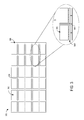
- FIG. 3 shows an example phase modulating image producing panel 300 comprising a plurality of tiled holograms 302 defined by gaps, with addressing lines 304 of a bus 306 located within the gaps.
- the panel may include a large number of smaller panels (e.g., LCoS devices), which may be formed on the same substrate or may each be formed on separate substrates and then integrated on a large substrate, such as a printed circuit board.
- the panel may also be placed on a curved waveguide (e.g. section of a cylinder) and thus increasing the FOV while at the same time operating the phase modulating device closer to normal incidence.
- the digital holograms do not interface directly with any lenses, which allows the display panel to maintain a flat and thin configuration without bulky curved components. Such features may help to reduce the overall depth of the optical system to maintain a compact configuration.
- hologram-to-gap sizing may include a hologram that has a length of 5.4 mm and a height of 3 mm, separated from adjacent holograms via a gap that is approximately 0.5 mm in width or height.
- Such an aspect ratio of the hologram may correspond to a high resolution image of 1920 pixels by 1080 pixels with a 2.79 ⁇ m pixel pitch.
- the elements described above are presented for example, and other sizes, numbers, and/or arrangements of holograms may be utilized in a tiled phase modulating image producing panel system. For example, to produce 720p images, each hologram may be sized to accommodate a maximum of 1280 ⁇ 720 pixels.
- Gaps in the panel may enable more effective addressing schemes than panels without gaps between holograms. For example, the addressing limitations of an N ⁇ N device with 2N external connections are reduced if the device is divided into four smaller ones of N/2 ⁇ N/2 pixel devices.
- addressing lines can be placed between them and electronics to convert serial data into parallel that will then drive the device. As shown in the detail view A of FIG. 3 , the addressing lines may be connected to each corresponding hologram via a demultiplexer 308 .
- the bus 306 may provide all display data to all holograms in parallel as multiplexed information, and the demultiplexer 308 may provide the relevant data to an associated hologram.
- the data distributed by bus 306 above may instead be provided by an h-tree, a routed on-chip interconnect, a pipelined distribution tree, or any other suitable interconnect.
- the total amount of information transmitted to the panel may be reduced relative to panels without individually addressable holograms.
- the amount of data associated with an image portion presented by that hologram may be controlled to effectively increase or reduce the resolution of that portion of the image.
- portions of the image in a central (e.g., foveal) region of the user's vision may display a larger hologram that increases the image resolution relative to portions of the image outside of the foveal region.
- a central region of the user's vision may display a larger hologram that increases the image resolution relative to portions of the image outside of the foveal region.
- FIGS. 4A-4B illustrate modifying tiled hologram sizes (and the subsequent increase or decrease of the image resolution) based upon gaze direction.
- an amount of visual detail encoded in each hologram tile is represented by a size of boxed regions in the tile, wherein a larger number of smaller boxes represents less visual information, and a smaller number of larger boxes represents more visual information.
- the number of boxes represents the amount of duplicated information in the form of repeated holograms in that tile.
- larger holograms with less duplicated information may be used for the foveal viewing region while smaller holograms with more duplicated information may be used for the peripheral view.
- the bus or other data interconnect sends all the information to all the sub-pixel blocks and each block reads the information it utilizes (e.g., the information addressed to that block).
- the bus may contain significantly less information than if each pixel was individually addressed, the bandwidth of the device may be reduced.
- a user's visual field is represented by the three circles in FIG. 4A .
- the user's visual field may be centered at an intersection between a gaze direction and the display device/display panel, and regions of the visual field may be selected based on a calibration or a default setting indicating typical edges of vision range (e.g., a region in which a user is able to focus most clearly, out to a peripheral region of the user's vision).
- a calibration or a default setting indicating typical edges of vision range e.g., a region in which a user is able to focus most clearly, out to a peripheral region of the user's vision.
- an area inside innermost circle 404 a may correspond to a central or foveal region of the user's vision.
- An area inside middle circle 406 a but outside of innermost circle 404 a may correspond to an intermediate region of the user's vision.
- An area inside outermost circle 408 a but outside of innermost circle 404 a and middle circle 406 a may correspond to a peripheral region of the user's vision.
- the granularity, shape, and size of the depicted visual regions is presented for example and is not intended to be limiting in any manner. Further, the description of the areas as corresponding to foveal, intermediate, and peripheral regions is illustrative, and hologram areas may not correspond anatomically to these visual regions in various examples.
- holograms that fall within the foveal visual region are controlled to produce image portions having a relatively higher resolution.
- the resolution of that hologram declines.
- holograms outside of the outermost circle 408 a are controlled to produce image portions having a relatively lower resolution (e.g., the lowest resolution of the holograms and/or a minimum resolution of the panel).
- some holograms may overlap intersections between visual regions.
- the resolution of each tiled hologram is based on the closest region to the foveal region in which that hologram is located.
- the hologram is used to produce an image portion having a resolution associated with the foveal region (e.g., a high resolution).
- a resolution associated with the foveal region e.g., a high resolution
- the resolution may be based on the furthest region to the foveal region in which the hologram is located.
- FIG. 4B illustrates movement of a location of intersection between the user's gaze direction and the display device/panel 400 .
- the resolution of hologram tiles changes to move the foveal/intermediate/peripheral regions, and thereby increase or decrease the resolutions of the hologram tiles accordingly.
- the system maintains the higher resolution imagery in the foveal area of the holograms, while decreasing resolution outside of this area to reduce computational resource usage.
- Phase modulating liquid crystal (LC) devices are typically slower than similar amplitude modulating devices, as a ⁇ 2 ⁇ phase delay is encountered for phase modulation in contrast to ⁇ for polarization (and thus amplitude) modulation.
- speed reduces, making color sequential displays potentially more difficult to achieve.
- One approach into solving this issue is to use color filters on top of each hologram pixel.
- the red, green, and blue filters may not be placed on a regular array, as placing color filters on a regular array may effectively reduce the spatial frequency of the hologram and therefore its deflection angle.
- any additional repetitive patterns will introduce persistent unwanted artifacts in the image.
- filters may be arranged in a pseudo-random way on the display device so they can still access all the angles.
- a 3 megapixel (MPix) device can have 1Mpix red, 1Mpix green and 1Mpix blue filters.
- efficiency is reduced as, at any moment, only one third of the light is transmitted through the color filters.
- another possible way to display color images may be to use many smaller blocks of pixels, where each block is illuminated by a single color. This may help to avoid a loss in efficiency, but may pose challenges in light of the potentially sub-mm size of the blocks.
- FIG. 5 shows an example optical system 500 that utilizes a volume hologram to deliver light to a phase modulating image panel.
- Optical system 500 also may be utilized with the display device of FIG. 1 .
- Optical system 500 includes a coherent illumination source 502 comprising a red laser 502 R, a green laser 502 G, and a blue laser 502 B. More generally, coherent light may be emitted from a number of sources including single mode lasers, multimode lasers, superluminescent diodes (SLDs) and even certain LEDs.
- SLDs superluminescent diodes
- Fully coherent light may not be used in all cases, but the spatial and temporal coherence may be controlled such that light can be diffracted and form an image.
- the beams from each laser are combined in beam-conditioning optic 504 , which aligns the beams along the same optical axis and adjusts the exit pupil of the aligned beams to the desired geometry.
- the beam may be relatively long and narrow—e.g., 20 ⁇ 2 millimeters (mm) in cross section—with the long edge parallel to the illuminated face of a volume hologram 506 and to the illuminated face of the image-forming optic 508 .
- the short edge of the beam may be normal to the illuminated face of the image-forming optic, though other geometries are contemplated as well.
- the coherent illumination source may include a single laser.
- the coherent illumination source may include lasers of any suitable wavelength (infrared, near-infrared, ultraviolet) and provide a substantially flat wave front for each wavelength.
- the volume hologram 506 is configured to receive coherent incident light 510 and to redirect the coherent light into the image-forming optic 508 .
- at least some image content may be encoded in incident light 510 that illuminates image-forming optic 508 .
- the role of the image-forming optic may be to change some property of the encoded image—its position, focal plane, orientation, brightness, polarization state, or correct for optical aberrations, etc.
- the incident light may provide neutral (e.g., non-image carrying) illumination of the image-forming optic, whose role is to form the desired image by releasing an engineered or controlled reflection.
- the volume hologram 506 may take any suitable arrangement.
- the volume hologram 506 may include a plurality (e.g., three) of different Bragg gratings arranged in parallel layers (e.g., each Bragg grating diffracting a different wavelength of light, such as the red, green, and blue light from the associated lasers 502 R/G/B).
- Each Bragg grating may include a series of substantially planar regions of a first refractive index, arranged in parallel in a substrate material of a second refractive index, higher or lower than the first.
- Each Bragg grating may efficiently reflecting light of a narrow range of wavelengths when such light is received over a narrow range of incidence angles.
- the wavelength and incidence-angle ranges are selectable, being determined by the orientation and pitch of planar regions, which are ‘burned in’ during recording of the volume hologram.
- the angle of release of the diffracted rays is determined by the period of the Bragg grating, while the angle of the rays that will excite the grating is determined by the direction of the grating vector.
- angular selectivity increases with the thickness of the Bragg grating; a thickness of 25-100 microns may provide an angular sensitivity of one degree.
- each Bragg grating may be transparent to light outside of its selected wavelength range.
- equivalent incidence and reflection angles may be selected for all Bragg gratings (e.g., all three Bragg gratings), so that the stack of Bragg gratings can receive red, green, and blue light in the same beam and reflect all three colors in the same direction, to illuminate the image-forming optic at the same near-normal incidence.
- different Bragg gratings may be configured to receive light at different incidence angles and to illuminate the image-forming optic at the same or different incidence angles.
- each Bragg grating redirects the incident beam by an angle determined by its grating period. Therefore, rays may be incident on the image-forming optic at normal or near-normal incidence even though the volume hologram is not oriented 45 degrees to an exit pupil, as a conventional beam splitter would be. This feature may help to reduce the depth of the optical system, potentially by orders of magnitude, relative to other optical systems.
- volume hologram 506 may include a single Bragg grating for that color.
- other types of volume holographic structures besides Bragg gratings may be used to achieve analogous results. Examples include configurations where the volume hologram incorporates a holographic lens to focus or defocus the incoming or reflected beam.
- the Bragg gratings of the volume hologram 506 may be transparent outside of the narrow range of angles in which incident light is diffracted.
- the narrow range may be centered on an optical axis, where the incidence and observation angles are equal. Accordingly, an exit pupil of the image-forming optic 508 will appear unobstructed to the observer, except in the neighborhood of a central optical axis, and parallel observation axes, where the volume hologram diverts the reflected image light back in the direction of coherent illumination source 502 .
- image rays may be rejected over a small range of angles, both horizontal and vertical, relative to the incidence angle or over a large range of angles.
- the phase-modulating display panel 508 may be configured to encode a Fresnel lens or other aberration.
- an effect of the aberration is to shift the focal plane of the formed image.
- such an optic will release numerous rays parallel to the zero-order component, all rejected by volume hologram 506 , the rejected rays will now originate from all portions of the image, instead of one cluster in the middle of the image.
- the image content is protected at the expense of a minor reduction in brightness and contrast.
- the zero-order component experiences none of the phase modulation induced by the image-forming optic, and therefore is not diverted by a holographic Fresnel lens or other aberration.
- removal of the unwanted zero-order illumination reflection remains efficient.
- FIG. 5 also shows that the volume hologram may be sandwiched between a pair of thin-layer prisms 512 .
- the prisms may be index-matched to the grating material to avoid Fresnel reflections from substrate material of the volume hologram.
- the volume hologram may include an antireflective coating—e.g., an interference filter.
- a physical lens 514 e.g., a refractive or diffractive lens
- the physical lens depending on its focal length and other properties, may be configured to shift the focal plane of the formed image back to its original position, or to shift it further in the same direction as the encoded Fresnel lens.
- physical lens 514 , the sandwiched volume hologram 506 , and image-forming optic 508 may be integrated into the same optical component.
- the above example of an optical system including a holographic optical element is exemplary in nature, and any suitable holographic optical element and associated optical configurations may be utilized.
- FIG. 6 is a flow chart illustrating an example method 600 of displaying images via a holographic near-eye display device, such as an HMD device utilizing optical system 200 of FIG. 2 .
- method 600 includes displaying an image via a phase modulating image producing panel configured as a plurality of tiled holograms.
- method 600 includes tracking a gaze direction of a user, for example, via an eye-tracking system of an HMD device, and at 606 , determining if the gaze direction has changed (e.g., by a threshold amount from a last measured gaze direction). For example, it may be determined whether a location of gaze intersection between the gaze direction and the display (e.g., the tiled holograms), has changed.
- method 600 comprises one or more of maintaining, at 608 , a resolution of the holograms and/or maintaining, at 610 , a direction at which light is emitted from a directable light source to maintain a location of higher resolution imagery and/or an eyebox.
- method 600 comprises one or more of selectively changing, at 612 , a resolution of holograms based on the location of the holograms relative to the gaze direction and/or adjusting, at 614 , a direction of the light source to adjust a location at which the image is viewable, respectively.
- the methods and processes described herein may be tied to a computing system of one or more computing devices.
- such methods and processes may be implemented as a computer-application program or service, an application-programming interface (API), a library, and/or other computer-program product.
- API application-programming interface
- FIG. 7 schematically shows a non-limiting embodiment of a computing system 700 that can enact one or more of the methods and processes described above.
- Computing system 700 is shown in simplified form.
- Computing system 700 may take the form of one or more wearable devices (e.g., near-eye display devices and/or head-mounted display devices such as HMD 100 of FIG. 1 , etc.), personal computers, server computers, tablet computers, home-entertainment computers, network computing devices, gaming devices, mobile computing devices, mobile communication devices (e.g., smart phone), and/or other computing devices.
- wearable devices e.g., near-eye display devices and/or head-mounted display devices such as HMD 100 of FIG. 1 , etc.
- personal computers server computers, tablet computers, home-entertainment computers
- network computing devices e.g., gaming devices, mobile computing devices, mobile communication devices (e.g., smart phone), and/or other computing devices.
- gaming devices e.g., gaming devices, mobile computing devices, mobile
- Computing system 700 includes a logic device 702 and a storage device 704 .
- Computing system 700 may optionally include a display subsystem 706 , input subsystem 708 , communication subsystem 710 , and/or other components not shown in FIG. 7 .
- Logic device 702 includes one or more physical devices configured to execute instructions.
- the logic device may be configured to execute instructions that are part of one or more applications, services, programs, routines, libraries, objects, components, data structures, or other logical constructs.
- Such instructions may be implemented to perform a task, implement a data type, transform the state of one or more components, achieve a technical effect, or otherwise arrive at a desired result.
- the logic device may include one or more processors configured to execute software instructions. Additionally or alternatively, the logic device may include one or more hardware or firmware logic devices configured to execute hardware or firmware instructions. Processors of the logic device may be single-core or multi-core, and the instructions executed thereon may be configured for sequential, parallel, and/or distributed processing. Individual components of the logic device optionally may be distributed among two or more separate devices, which may be remotely located and/or configured for coordinated processing. Aspects of the logic device may be virtualized and executed by remotely accessible, networked computing devices configured in a cloud-computing configuration.
- Storage device 704 includes one or more physical devices configured to hold instructions executable by the logic device to implement the methods and processes described herein. When such methods and processes are implemented, the state of storage device 704 may be transformed—e.g., to hold different data.
- Storage device 704 may include removable and/or built-in devices.
- Storage device 704 may include optical memory (e.g., CD, DVD, HD-DVD, Blu-Ray Disc, etc.), semiconductor memory (e.g., RAM, EPROM, EEPROM, etc.), and/or magnetic memory (e.g., hard-disk drive, floppy-disk drive, tape drive, MRAM, etc.), among others.
- Storage device 704 may include volatile, non-volatile, dynamic, static, read/write, read-only, random-access, sequential-access, location-addressable, file-addressable, and/or content-addressable devices.
- storage device 704 includes one or more physical devices.
- aspects of the instructions described herein alternatively may be propagated by a communication medium (e.g., an electromagnetic signal, an optical signal, etc.) that is not held by a physical device for a finite duration.
- a communication medium e.g., an electromagnetic signal, an optical signal, etc.
- logic device 702 and storage device 704 may be integrated together into one or more hardware-logic components.
- Such hardware-logic components may include field-programmable gate arrays (FPGAs), program- and application-specific integrated circuits (PASIC/ASICs), program- and application-specific standard products (PSSP/ASSPs), system-on-a-chip (SOC), and complex programmable logic devices (CPLDs), for example.
- FPGAs field-programmable gate arrays
- PASIC/ASICs program- and application-specific integrated circuits
- PSSP/ASSPs program- and application-specific standard products
- SOC system-on-a-chip
- CPLDs complex programmable logic devices
- Display subsystem 706 may be used to present a visual representation of data held by storage device 704 .
- This visual representation may take the form of a graphical user interface (GUI).
- GUI graphical user interface
- the state of display subsystem 706 may likewise be transformed to visually represent changes in the underlying data.
- Display subsystem 706 may include one or more display devices utilizing virtually any type of technology. Such display devices may be combined with logic device 702 and/or storage device 704 in a shared enclosure, or such display devices may be peripheral display devices.
- Input subsystem 708 may comprise or interface with one or more user-input devices such as a keyboard, mouse, touch screen, or game controller.
- the input subsystem may comprise or interface with selected natural user input (NUI) componentry.
- NUI natural user input
- Such componentry may be integrated or peripheral, and the transduction and/or processing of input actions may be handled on- or off-board.
- NUI componentry may include a microphone for speech and/or voice recognition; an infrared, color, stereoscopic, and/or depth camera for device vision and/or gesture recognition; a head tracker, eye tracker, accelerometer, and/or gyroscope for motion detection and/or intent recognition; as well as electric-field sensing componentry for assessing brain activity.
- Communication subsystem 710 may be configured to communicatively couple computing system 700 with one or more other computing devices.
- Communication subsystem 710 may include wired and/or wireless communication devices compatible with one or more different communication protocols.
- the communication subsystem may be configured for communication via a wireless telephone network, or a wired or wireless local- or wide-area network.
- the communication subsystem may allow computing system 700 to send and/or receive messages to and/or from other devices via a network such as the Internet.
- a display device including a phase modulating image producing panel, and a holographic optical element configured to receive collimated light and to output converging light toward the phase modulating image producing panel, the phase modulating image producing panel being configured to use at least a portion of the converging light to produce an image with collimated or diverging light.
- the display device may additionally or alternatively further include an eye-tracking system configured to track a gaze direction of a user of the display device.
- the display device may additionally or alternatively further include a directable light source controllable to direct light in a direction based upon the gaze direction to adjust a location at which the image is viewable.
- the display device may additionally or alternatively further include a diffractive optical element configured to form a plurality of spatially separated eyeboxes in which the image is viewable.
- the phase modulating image producing panel may additionally or alternatively be further controllable to modify a resolution of each of a plurality of portions of the image based on the gaze direction.
- the phase modulating image producing panel may additionally or alternatively be controllable to produce the image via an array of tiled holograms.
- Each of the tiled holograms may additionally or alternatively be individually-addressable via addressing lines of a bus, an h-tree interconnect, a routed on-chip interconnect, or a pipelined distribution tree interconnect, and controlling the resolution of each of the tiled holograms may additionally or alternatively include sending higher resolution data to tiled holograms in a foveal vision region than to tiled holograms in another vision region of the display.
- the array of tiled holograms may additionally or alternatively be formed by providing multiple separate image producing panels that are spaced from one another.
- the display device may additionally or alternatively further include a spatial light modulator, and the phase modulating image producing panel may additionally or alternatively be configured to reflect converging light of a zero order toward the spatial light modulator for image production.
- the spatial light modulator may additionally or alternatively be controllable to produce one or more peripheral images configured to surround the image and a correction image configured to selectively attenuate the image. Any or all of the above-described examples may be combined in any suitable manner in various implementations.
- an example display device including a light source, a phase modulating image producing panel configured to produce a holographic image via light from the light source, an eye-tracking system, a processor configured to execute computer-readable instructions, and a storage device comprising instructions stored thereon that are executable by the processor to track, via the eye-tracking system, a gaze intersection with the display device, control the phase modulating image producing panel to produce an image via an array of tiled holograms formed via the phase modulating image producing panel, the array of tiled holograms comprising a region of higher resolution tiled holograms closer to a gaze intersection and a region of lower resolution tiled holograms farther from the gaze intersection, detect, via the eye-tracking system, a change in the gaze intersection, and control the phase modulating image producing panel to increase a resolution of the region of lower resolution tiled holograms and to decrease a resolution of the region of higher resolution tiled holograms based upon the change in the gaze intersection.
- Each of the tiled holograms may additionally or alternatively be individually-addressable. Decreasing the image resolution of the region of lower resolution tiled holograms may additionally or alternatively include sending a larger number of replicated copies of smaller tiled holograms in the region of lower resolution holograms.
- the display device may additionally or alternatively further include a plurality of phase modulating image display panels configured to form the tiled holograms, and each phase modulating image panel may additionally or alternatively be spaced from adjacent phase modulating image display panels.
- the display device may additionally or alternatively further include a spatial light modulator, and the phase modulating image producing panel may additionally or alternatively be configured to reflect converging light of a zero order toward the spatial light modulator for production of a different image than the image produced by the tiled holograms.
- the different image may additionally or alternatively include one or more of a peripheral image configured to surround the image produced by the tiled holograms and a correction image configured to selectively attenuate the image produced by the tiled holograms. Any or all of the above-described examples may be combined in any suitable manner in various implementations.
- an example display device including a light source, a phase modulating image producing panel, a spatial light modulator, and a holographic optical element
- the holographic optical element may additionally or alternatively be configured to receive collimated light from the light source and to output converging light toward the phase modulating image producing panel
- the phase modulating image producing panel may additionally or alternatively be configured to form a foveal holographic image from one or more orders of diffracted light and to reflect converging light of a zero order toward the spatial light modulator for production of a different image.
- the display device may additionally or alternatively include an eye-tracking system configured to track a gaze direction of a user of the display device, and the phase modulating image producing panel may additionally or alternatively be further controllable to modify a resolution of each of a plurality of portions of the foveal image based on the gaze direction.
- the phase modulating image producing panel may additionally or alternatively be controllable to produce the foveal image via an array of tiled holograms, each of the tiled holograms may additionally or alternatively be individually-addressable, and controlling the resolution of each of the tiled holograms may additionally or alternatively include sending higher resolution data to tiled holograms in the center of the foveal vision region than to tiled holograms in another vision region of the display.
- the display device may additionally or alternatively further include a plurality of phase modulating image display panels configured to form the tiled holograms, and each tiled hologram may additionally or alternatively be spaced from adjacent tiled holograms.
- the light source may additionally or alternatively include a directable light source controllable to direct light in a direction based upon the gaze direction to adjust a location at which the foveal image is viewable, and the display device may additionally or alternatively further include a diffractive optical element configured to form a plurality of spatially separated eyeboxes in which the foveal and surround images are viewable.
- the spatial light modulator may additionally or alternatively be further configured to selectively attenuate the foveal image displayed by the phase modulating image producing panel.
- the different image may additionally or alternatively include one or more of a peripheral image configured to surround the foveal image and a correction image configured to selectively attenuate the foveal image. Any or all of the above-described examples may be combined in any suitable manner in various implementations.
Landscapes
- Physics & Mathematics (AREA)
- General Physics & Mathematics (AREA)
- Engineering & Computer Science (AREA)
- Optics & Photonics (AREA)
- Theoretical Computer Science (AREA)
- Computer Hardware Design (AREA)
- Holo Graphy (AREA)
- Diffracting Gratings Or Hologram Optical Elements (AREA)
Abstract
Embodiments are disclosed for display devices including holographic optical elements for directing light toward image producing panels. An example display device includes a phase modulating image producing panel, and a holographic optical element configured to receive collimated light and to output converging light toward the phase modulating image producing panel, the phase modulating image producing panel being configured to use at least a portion of the converging light to produce an image with collimated or diverging light.
Description
A near-eye display device may be implemented as a head-mounted display system that allows users to view holographically-generated images as an immersive experience. Images displayed/projected by a near-eye display device may be produced in various manners. For example, near-eye reality display devices may utilize display panels positioned within a user's field of view, while others may utilize waveguides to deliver to a user's eyes imagery produced elsewhere in the system.
Examples are disclosed that relate to holographic near-eye display systems. One example provides a display device including a phase modulating image producing panel, and a holographic optical element configured to receive collimated light and to output converging light toward the phase modulating image producing panel, the phase modulating image producing panel being configured to use at least a portion of the converging light to produce an image with collimated or diverging light.
This Summary is provided to introduce a selection of concepts in a simplified form that are further described below in the Detailed Description. This Summary is not intended to identify key features or essential features of the claimed subject matter, nor is it intended to be used to limit the scope of the claimed subject matter. Furthermore, the claimed subject matter is not limited to implementations that solve any or all disadvantages noted in any part of this disclosure.
Optical systems for near-eye display systems, such as head-mounted display (HMD) devices, may suffer from various drawbacks. For example, HMDs that utilize conventional optics may provide a wide field of view and a large eyebox in which imagery is viewable, but also may be bulky and heavy. HMDs that utilize waveguide optics to deliver to a user's eye an image produced by a panel located out of the user's field of view may allow the use of a relatively thin lens, but can have a small field of view for virtual image display, and can also be heavy. Also, as the light bounces in the waveguide many times, the waveguide has to be of high manufacturing fidelity. Scanning mirror or scanning fiber devices, in which the direction of projected light can be mechanically controlled to produce a scanned image, may be lightweight and compact, but the eyebox and the field of view of such devices each may be smaller than those of waveguide or conventional optical systems.
Accordingly, examples of near eye displays of compact size that may display virtual imagery with a wide field of view and a wide effective eyebox are disclosed herein. Briefly, a near-eye display device may utilize a holographic optical element that receives collimated light from a light source and outputs converging light toward a phase modulating image producing panel, such as a phase modulating LCOS (liquid crystal on silicon) panel. The phase modulating image producing panel may be controlled to form a hologram that produces an image with collimated or diverging (e.g., weakly diverging) light for display to a user. In some examples, to reduce a data processing load, the image producing panel may be effectively divided into a plurality of holograms (“tiled holograms”), each of which collimates the converging light from the holographic optical element and contributes to the creation of the image. By returning the light to parallel rays, the image producing panel is able to compensate for the lens effect of the holographic optical element. The use of converging light incident on the LCOS allows the resolution to be reduced for the holograms of the LCOS, as less resolution is spent bending the light toward the eye than if the hologram were illuminated with parallel light. In some examples, color filters may be placed on top of hologram pixels for achieving non-sequential color operation.
Further, to conserve computing device resources, a foveated image display may be used to display higher resolution imagery adjacent to the gaze direction of a user, and lower resolution imagery peripheral to the gaze direction. Foveation of displayed imagery may be accomplished in various manners. For example, where tiled holograms are used, the resolution of each hologram may be controlled based upon a determined gaze direction of a user, such that a resolution may be increased for hologram tiles closer to a user's gaze direction and decreased for hologram tiles that are peripheral to the gaze direction. The resolution of the projected image is controlled by the size of the tile while the angular extend of the image is determined by the pixel spacing, which is the same for all the tiled holograms irrespective of their size.
Alternatively or additionally, light output by the phase modulating image producing panel (e.g. light that is not diffracted but is merely reflected or collimated by the phase modulating image producing panel) may be used to illuminate a second image producing panel, such as an amplitude modulating panel, to display additional imagery. The second display panel also may be used for modifying the image displayed by the first image producing panel, e.g., to correct aberrations in the image or to mask unwanted artifacts. In this way, the near-eye display may avoid the use of curved refractive optics, thereby allowing the optical system to achieve a compact profile. The above-described features, as well as others, are described in greater detail below.
The HMD device 100 includes a controller 104 configured to control operation of the display 102. Control of operation of the display 102 may be additionally or alternatively controlled by one or more computing devices (e.g., remote from the HMD device 100) in communication with the HMD device 100. The controller 104 may include a logic device and a storage device, as discussed in more detail below with respect to FIG. 7 . The logic device and storage device may be in communication with various sensors and display system components of the HMD device 100.
The HMD device 100 also includes a holographic display system 106 controlled by the controller. Example display systems for use as holographic display system 106 are described in more detail below.
The HMD device 100 further may include various sensors and related systems to provide information to the controller 104. Such sensors may include, but are not limited to, a microphone array, one or more outward facing image sensors 108, one or more inward facing image sensors 109, and an inertial measurement unit (IMU) 110.
The one or more outward facing image sensors 108 may be configured to capture visual data of the physical environment in which the HMD device 100 is located. Such visual data of the physical environment may be used to provide video-based augmented reality display data to the holographic display system 106. In this way, a live or semi-live video/image feed of the user's real-world environment, as imaged by the outward facing image sensors 108, may be displayed via the holographic display system 106 to simulate a see-through display system. Virtual objects may be displayed over the images of the real-world environment to present an augmented reality scene to the user.
The one or more inward facing image sensors 109 may be configured to capture visual data corresponding to a user of the HMD device 100. For example, the one or more inward facing image sensors 109 may be included in an eye tracking system to capture image data of a user's eye for determining a user's gaze direction. The determined gaze direction may be utilized to determine an intersection between the user's gaze direction and the display device (e.g., the image producing display panel), and thus to determine which region of the display panel is within a foveal region of the user's field of view and which region of the display panel the user is viewing within a peripheral region of the user's field of view.
The HMD device 100 may further include speakers 114 and 116 configured to output sound to the wearer of the HMD device. The speakers 114 and 116 may be positioned on each side frame portion of the HMD device proximate to the wearer's ears.
Light is reflected (zero order) and diffracted (first order and higher orders) from the phase modulating image producing panel 210 and transmitted through the holographic optical element 208. The phase modulating image display panel 210 produces a viewable image typically via first order diffracted light. Some implementations of the display system may be configured to use other orders of diffracted light. Further, the phase modulating display panel 210 also may be controlled to convert the converging light from the holographic optical element 208 back to collimated light. In contrast, the zero order light remains converging, reflected by the phase modulating display panel 210, will not appear as a bright spot in the users field of view (as it would if collimated), but rather will appear as being substantially uniform in intensity across the eyebox.
In view of this, the optical system 200 may optionally include an amplitude modulating spatial light modulator 212 (e.g., an LCD panel) to produce additional imagery via the reflected light from the phase modulating device. Undiffracted light (including the unwanted zero order light) will appear as a uniform brightness image to the user. Turning certain hologram tiles intentionally off or displaying an appropriate phase pattern may create the desired backlight for the amplitude modulating spatial light modulator 212. Where the spatial light modulator 212 comprises a transmissive LCD, the optical system further may include polarizers 214 a and 214 b to respectively polarize and filter the light passing through the spatial light modulator 212 in order to achieve amplitude modulation.
The amplitude modulating spatial light modulator 212 may be used to produce any suitable imagery. For example, the spatial light modulator 212 may be controlled to produce an image in a peripheral region of a user's vision. Such an image may be a lower resolution image than the phase modulating image producing panel 210, and/or may be displayed across a wider field of view than the image from phase modulating image producing panel 210. This may help to reduce the computational burden compared to presenting peripheral and foveal images via the phase modulating image producing panel 210. In other examples, the spatial light modulator 212 may be controlled to produce an image within the same field of view as the phase modulating image producing panel 210 to affect the appearance of the image produced by panel 210. For example, the spatial light modulator 212 may be used to attenuate the image from the image producing panel 210 to reduce the intensity of bright spots and/or to perform other image corrections.
In some examples, the light reflected and diffracted from the phase modulating image producing panel 210 and/or the light output by the spatial light modulator 212 may be provided to a diffractive optical element 216 (e.g., a fanout grating in one non-limiting example) to replicate the exit pupil of the optical system. This may help to create an effectively larger eyebox. The replicated eyeboxes (e.g., formed by light rays 218 a and 218 b) may be spatially separated from the original eyebox (e.g., formed by light rays 218 c) in order to ensure that a user views a single eyebox at a given eye position/gaze direction.
In some examples, an eye-tracking system may be used to determine or track a pupil position of a user's eye. In such examples, the multiple eyeboxes may be formed by using a lower frequency switchable grating and an adjustable light source controllable to emit light at different angles based on a location of the pupil. For example, as illustrated in FIG. 2 , the light source 202 may be controllable to emit light in a range of angles from −α to +α, wherein α may have any suitable value. As one non-limiting example, the light source may be controllable from −10 to +10 degrees from a center of the angular range, and the eyeboxes produced by the diffractive optical element 216 may be angularly spaced by 20 degrees.
Because a hologram encodes information in the frequency domain, each hologram pixel of a hologram tile contributes to an entire section of the FOV/image. The size of the image (e.g., the angular extend of the image) depends on the pixel spacing and the encoded lens in the holographic optical element. The pixel density of the image (e.g., the angular separation of the image pixels) depends on the hologram pixels (e.g., the hologram tile size). Therefore, it is possible to increase or decrease the angular density of image pixels with a corresponding increase or decrease in the fidelity of the image while keeping the pixel spacing of the hologram and/or phase modulating device constant. It is also possible to create gaps in the hologram. As long as the gaps are significantly smaller than the pupil of the eye, and the eye is sufficiently close so it cannot focus on these gaps, the eye will not perceive them. These gaps may be non-existing pixels, pixels that are not switched on, pixels covered with a color mask, or may take any other suitable form. These gaps may be used for passing the addressing lines and thus improving the scalability of the device.
Accordingly, FIG. 3 shows an example phase modulating image producing panel 300 comprising a plurality of tiled holograms 302 defined by gaps, with addressing lines 304 of a bus 306 located within the gaps. The panel may include a large number of smaller panels (e.g., LCoS devices), which may be formed on the same substrate or may each be formed on separate substrates and then integrated on a large substrate, such as a printed circuit board. The panel may also be placed on a curved waveguide (e.g. section of a cylinder) and thus increasing the FOV while at the same time operating the phase modulating device closer to normal incidence. Because the Fourier domain or conjugate plane of an image may be created without the use of additional optics, the digital holograms do not interface directly with any lenses, which allows the display panel to maintain a flat and thin configuration without bulky curved components. Such features may help to reduce the overall depth of the optical system to maintain a compact configuration.
Providing addressing lines within the gaps may enable the device to be scalable to accommodate additional or fewer holograms. A non-limiting example of hologram-to-gap sizing may include a hologram that has a length of 5.4 mm and a height of 3 mm, separated from adjacent holograms via a gap that is approximately 0.5 mm in width or height. Such an aspect ratio of the hologram may correspond to a high resolution image of 1920 pixels by 1080 pixels with a 2.79 μm pixel pitch. The elements described above are presented for example, and other sizes, numbers, and/or arrangements of holograms may be utilized in a tiled phase modulating image producing panel system. For example, to produce 720p images, each hologram may be sized to accommodate a maximum of 1280×720 pixels.
Gaps in the panel may enable more effective addressing schemes than panels without gaps between holograms. For example, the addressing limitations of an N×N device with 2N external connections are reduced if the device is divided into four smaller ones of N/2×N/2 pixel devices. As mentioned above, by creating gaps between groups of pixels, addressing lines can be placed between them and electronics to convert serial data into parallel that will then drive the device. As shown in the detail view A of FIG. 3 , the addressing lines may be connected to each corresponding hologram via a demultiplexer 308. The bus 306 may provide all display data to all holograms in parallel as multiplexed information, and the demultiplexer 308 may provide the relevant data to an associated hologram. In other examples, the data distributed by bus 306 above may instead be provided by an h-tree, a routed on-chip interconnect, a pipelined distribution tree, or any other suitable interconnect. In either case, the total amount of information transmitted to the panel may be reduced relative to panels without individually addressable holograms. By individually addressing each hologram, the amount of data associated with an image portion presented by that hologram may be controlled to effectively increase or reduce the resolution of that portion of the image. For example, as an eye of a user of the display device moves around to focus on different parts of a produced image, portions of the image in a central (e.g., foveal) region of the user's vision may display a larger hologram that increases the image resolution relative to portions of the image outside of the foveal region. In this way, by increasing or decreasing the size of each hologram tile, the resolution of the portion of the image presented at each angle by each hologram may be dynamically controlled.
A user's visual field is represented by the three circles in FIG. 4A . The user's visual field may be centered at an intersection between a gaze direction and the display device/display panel, and regions of the visual field may be selected based on a calibration or a default setting indicating typical edges of vision range (e.g., a region in which a user is able to focus most clearly, out to a peripheral region of the user's vision). For example, an area inside innermost circle 404 a may correspond to a central or foveal region of the user's vision. An area inside middle circle 406 a but outside of innermost circle 404 a may correspond to an intermediate region of the user's vision. An area inside outermost circle 408 a but outside of innermost circle 404 a and middle circle 406 a may correspond to a peripheral region of the user's vision. The granularity, shape, and size of the depicted visual regions is presented for example and is not intended to be limiting in any manner. Further, the description of the areas as corresponding to foveal, intermediate, and peripheral regions is illustrative, and hologram areas may not correspond anatomically to these visual regions in various examples.
As illustrated in FIG. 4A , holograms that fall within the foveal visual region are controlled to produce image portions having a relatively higher resolution. As the distance between a given hologram and the central/foveal visual region grows, the resolution of that hologram declines. For example, holograms outside of the outermost circle 408 a are controlled to produce image portions having a relatively lower resolution (e.g., the lowest resolution of the holograms and/or a minimum resolution of the panel). As illustrated, some holograms may overlap intersections between visual regions. In the illustrated example, the resolution of each tiled hologram is based on the closest region to the foveal region in which that hologram is located. Accordingly, if a hologram is located in both the foveal region and the intermediate region, the hologram is used to produce an image portion having a resolution associated with the foveal region (e.g., a high resolution). However, in other examples, the resolution may be based on the furthest region to the foveal region in which the hologram is located.
As the eye moves, the resolution provided by the different holograms may change if the visual region in which that hologram is located changes. FIG. 4B illustrates movement of a location of intersection between the user's gaze direction and the display device/panel 400. In response to the movement, the resolution of hologram tiles changes to move the foveal/intermediate/peripheral regions, and thereby increase or decrease the resolutions of the hologram tiles accordingly. In this manner, the system maintains the higher resolution imagery in the foveal area of the holograms, while decreasing resolution outside of this area to reduce computational resource usage.
Phase modulating liquid crystal (LC) devices are typically slower than similar amplitude modulating devices, as a ˜2π phase delay is encountered for phase modulation in contrast to ˜π for polarization (and thus amplitude) modulation. As the thickness of an optical system increases, speed reduces, making color sequential displays potentially more difficult to achieve. One approach into solving this issue is to use color filters on top of each hologram pixel. However, unlike conventional display devices, the red, green, and blue filters may not be placed on a regular array, as placing color filters on a regular array may effectively reduce the spatial frequency of the hologram and therefore its deflection angle. Furthermore, any additional repetitive patterns will introduce persistent unwanted artifacts in the image. Instead, filters may be arranged in a pseudo-random way on the display device so they can still access all the angles. For example a 3 megapixel (MPix) device can have 1Mpix red, 1Mpix green and 1Mpix blue filters. In this case, efficiency is reduced as, at any moment, only one third of the light is transmitted through the color filters. Thus, another possible way to display color images may be to use many smaller blocks of pixels, where each block is illuminated by a single color. This may help to avoid a loss in efficiency, but may pose challenges in light of the potentially sub-mm size of the blocks.
The use of tiled hologram resolution control to display foveated images can be used with any suitable optical system other than that of FIG. 3 . FIG. 5 shows an example optical system 500 that utilizes a volume hologram to deliver light to a phase modulating image panel. Optical system 500 also may be utilized with the display device of FIG. 1 . Optical system 500 includes a coherent illumination source 502 comprising a red laser 502R, a green laser 502G, and a blue laser 502B. More generally, coherent light may be emitted from a number of sources including single mode lasers, multimode lasers, superluminescent diodes (SLDs) and even certain LEDs. Fully coherent light may not be used in all cases, but the spatial and temporal coherence may be controlled such that light can be diffracted and form an image. The beams from each laser are combined in beam-conditioning optic 504, which aligns the beams along the same optical axis and adjusts the exit pupil of the aligned beams to the desired geometry. In one implementation, the beam may be relatively long and narrow—e.g., 20×2 millimeters (mm) in cross section—with the long edge parallel to the illuminated face of a volume hologram 506 and to the illuminated face of the image-forming optic 508. In one implementation, the short edge of the beam may be normal to the illuminated face of the image-forming optic, though other geometries are contemplated as well. Combined use of red, green, and blue lasers in the coherent illumination source enables a color image to be formed at image-forming optic 508. In other implementations, a monochromatic image may be desired. As such, the coherent illumination source may include a single laser. In general, the coherent illumination source may include lasers of any suitable wavelength (infrared, near-infrared, ultraviolet) and provide a substantially flat wave front for each wavelength.
The volume hologram 506 is configured to receive coherent incident light 510 and to redirect the coherent light into the image-forming optic 508. In some examples, at least some image content may be encoded in incident light 510 that illuminates image-forming optic 508. There, the role of the image-forming optic may be to change some property of the encoded image—its position, focal plane, orientation, brightness, polarization state, or correct for optical aberrations, etc. In other examples, the incident light may provide neutral (e.g., non-image carrying) illumination of the image-forming optic, whose role is to form the desired image by releasing an engineered or controlled reflection.
The volume hologram 506 may take any suitable arrangement. In one example, the volume hologram 506 may include a plurality (e.g., three) of different Bragg gratings arranged in parallel layers (e.g., each Bragg grating diffracting a different wavelength of light, such as the red, green, and blue light from the associated lasers 502R/G/B). Each Bragg grating may include a series of substantially planar regions of a first refractive index, arranged in parallel in a substrate material of a second refractive index, higher or lower than the first. Each Bragg grating may efficiently reflecting light of a narrow range of wavelengths when such light is received over a narrow range of incidence angles. Light received outside of the narrow wavelength and incidence-angle ranges is transmitted with high efficiency. Moreover, the wavelength and incidence-angle ranges are selectable, being determined by the orientation and pitch of planar regions, which are ‘burned in’ during recording of the volume hologram. In particular, the angle of release of the diffracted rays is determined by the period of the Bragg grating, while the angle of the rays that will excite the grating is determined by the direction of the grating vector. Furthermore, angular selectivity increases with the thickness of the Bragg grating; a thickness of 25-100 microns may provide an angular sensitivity of one degree.
The fact that each Bragg grating may be transparent to light outside of its selected wavelength range makes it possible to combine two, three, or more Bragg gratings in a stacked configuration. In practice, equivalent incidence and reflection angles may be selected for all Bragg gratings (e.g., all three Bragg gratings), so that the stack of Bragg gratings can receive red, green, and blue light in the same beam and reflect all three colors in the same direction, to illuminate the image-forming optic at the same near-normal incidence. In other implementations, different Bragg gratings may be configured to receive light at different incidence angles and to illuminate the image-forming optic at the same or different incidence angles.
As noted above, each Bragg grating redirects the incident beam by an angle determined by its grating period. Therefore, rays may be incident on the image-forming optic at normal or near-normal incidence even though the volume hologram is not oriented 45 degrees to an exit pupil, as a conventional beam splitter would be. This feature may help to reduce the depth of the optical system, potentially by orders of magnitude, relative to other optical systems.
While the stacked Bragg-grating configuration described above may be used in some implementations, it is also possible to record two, three, or more Bragg gratings superposed in the same volume, using light of different wavelengths in concurrent or sequential exposures of the photopolymer. In such a hologram, the three superposed Bragg gratings still function independently. Naturally, if a monochromatic image is desired, volume hologram 506 may include a single Bragg grating for that color. Furthermore, other types of volume holographic structures besides Bragg gratings may be used to achieve analogous results. Examples include configurations where the volume hologram incorporates a holographic lens to focus or defocus the incoming or reflected beam.
The Bragg gratings of the volume hologram 506 may be transparent outside of the narrow range of angles in which incident light is diffracted. For the light reflecting from image-forming optic 508, the narrow range may be centered on an optical axis, where the incidence and observation angles are equal. Accordingly, an exit pupil of the image-forming optic 508 will appear unobstructed to the observer, except in the neighborhood of a central optical axis, and parallel observation axes, where the volume hologram diverts the reflected image light back in the direction of coherent illumination source 502. In practice, image rays may be rejected over a small range of angles, both horizontal and vertical, relative to the incidence angle or over a large range of angles.
Diversion of the reflected image light provides an efficient and highly selective mechanism to separate the zero order diffraction component of an image formed by a holographic image source, but also may create a small dark spot in the middle of the image. To remedy such issues, the phase-modulating display panel 508 may be configured to encode a Fresnel lens or other aberration. In some examples, an effect of the aberration is to shift the focal plane of the formed image. Although such an optic will release numerous rays parallel to the zero-order component, all rejected by volume hologram 506, the rejected rays will now originate from all portions of the image, instead of one cluster in the middle of the image. Thus, the image content is protected at the expense of a minor reduction in brightness and contrast. By definition, the zero-order component experiences none of the phase modulation induced by the image-forming optic, and therefore is not diverted by a holographic Fresnel lens or other aberration. Thus, removal of the unwanted zero-order illumination reflection remains efficient.
If the gaze direction has not changed (e.g. more than a threshold amount), then method 600 comprises one or more of maintaining, at 608, a resolution of the holograms and/or maintaining, at 610, a direction at which light is emitted from a directable light source to maintain a location of higher resolution imagery and/or an eyebox. On the other hand, if the gaze direction has changed (e.g., more than a threshold amount), then method 600 comprises one or more of selectively changing, at 612, a resolution of holograms based on the location of the holograms relative to the gaze direction and/or adjusting, at 614, a direction of the light source to adjust a location at which the image is viewable, respectively.
In some embodiments, the methods and processes described herein may be tied to a computing system of one or more computing devices. In particular, such methods and processes may be implemented as a computer-application program or service, an application-programming interface (API), a library, and/or other computer-program product.
The logic device may include one or more processors configured to execute software instructions. Additionally or alternatively, the logic device may include one or more hardware or firmware logic devices configured to execute hardware or firmware instructions. Processors of the logic device may be single-core or multi-core, and the instructions executed thereon may be configured for sequential, parallel, and/or distributed processing. Individual components of the logic device optionally may be distributed among two or more separate devices, which may be remotely located and/or configured for coordinated processing. Aspects of the logic device may be virtualized and executed by remotely accessible, networked computing devices configured in a cloud-computing configuration.
It will be appreciated that storage device 704 includes one or more physical devices. However, aspects of the instructions described herein alternatively may be propagated by a communication medium (e.g., an electromagnetic signal, an optical signal, etc.) that is not held by a physical device for a finite duration.
Aspects of logic device 702 and storage device 704 may be integrated together into one or more hardware-logic components. Such hardware-logic components may include field-programmable gate arrays (FPGAs), program- and application-specific integrated circuits (PASIC/ASICs), program- and application-specific standard products (PSSP/ASSPs), system-on-a-chip (SOC), and complex programmable logic devices (CPLDs), for example.
Another example provides a display device including a phase modulating image producing panel, and a holographic optical element configured to receive collimated light and to output converging light toward the phase modulating image producing panel, the phase modulating image producing panel being configured to use at least a portion of the converging light to produce an image with collimated or diverging light. The display device may additionally or alternatively further include an eye-tracking system configured to track a gaze direction of a user of the display device. The display device may additionally or alternatively further include a directable light source controllable to direct light in a direction based upon the gaze direction to adjust a location at which the image is viewable. The display device may additionally or alternatively further include a diffractive optical element configured to form a plurality of spatially separated eyeboxes in which the image is viewable. The phase modulating image producing panel may additionally or alternatively be further controllable to modify a resolution of each of a plurality of portions of the image based on the gaze direction. The phase modulating image producing panel may additionally or alternatively be controllable to produce the image via an array of tiled holograms. Each of the tiled holograms may additionally or alternatively be individually-addressable via addressing lines of a bus, an h-tree interconnect, a routed on-chip interconnect, or a pipelined distribution tree interconnect, and controlling the resolution of each of the tiled holograms may additionally or alternatively include sending higher resolution data to tiled holograms in a foveal vision region than to tiled holograms in another vision region of the display. The array of tiled holograms may additionally or alternatively be formed by providing multiple separate image producing panels that are spaced from one another. The display device may additionally or alternatively further include a spatial light modulator, and the phase modulating image producing panel may additionally or alternatively be configured to reflect converging light of a zero order toward the spatial light modulator for image production. In this example display device, the spatial light modulator may additionally or alternatively be controllable to produce one or more peripheral images configured to surround the image and a correction image configured to selectively attenuate the image. Any or all of the above-described examples may be combined in any suitable manner in various implementations.
Another example provides an example display device including a light source, a phase modulating image producing panel configured to produce a holographic image via light from the light source, an eye-tracking system, a processor configured to execute computer-readable instructions, and a storage device comprising instructions stored thereon that are executable by the processor to track, via the eye-tracking system, a gaze intersection with the display device, control the phase modulating image producing panel to produce an image via an array of tiled holograms formed via the phase modulating image producing panel, the array of tiled holograms comprising a region of higher resolution tiled holograms closer to a gaze intersection and a region of lower resolution tiled holograms farther from the gaze intersection, detect, via the eye-tracking system, a change in the gaze intersection, and control the phase modulating image producing panel to increase a resolution of the region of lower resolution tiled holograms and to decrease a resolution of the region of higher resolution tiled holograms based upon the change in the gaze intersection. Each of the tiled holograms may additionally or alternatively be individually-addressable. Decreasing the image resolution of the region of lower resolution tiled holograms may additionally or alternatively include sending a larger number of replicated copies of smaller tiled holograms in the region of lower resolution holograms. The display device may additionally or alternatively further include a plurality of phase modulating image display panels configured to form the tiled holograms, and each phase modulating image panel may additionally or alternatively be spaced from adjacent phase modulating image display panels. The display device may additionally or alternatively further include a spatial light modulator, and the phase modulating image producing panel may additionally or alternatively be configured to reflect converging light of a zero order toward the spatial light modulator for production of a different image than the image produced by the tiled holograms. The different image may additionally or alternatively include one or more of a peripheral image configured to surround the image produced by the tiled holograms and a correction image configured to selectively attenuate the image produced by the tiled holograms. Any or all of the above-described examples may be combined in any suitable manner in various implementations.
Another example provides an example display device including a light source, a phase modulating image producing panel, a spatial light modulator, and a holographic optical element, and the holographic optical element may additionally or alternatively be configured to receive collimated light from the light source and to output converging light toward the phase modulating image producing panel, and the phase modulating image producing panel may additionally or alternatively be configured to form a foveal holographic image from one or more orders of diffracted light and to reflect converging light of a zero order toward the spatial light modulator for production of a different image. The display device may additionally or alternatively include an eye-tracking system configured to track a gaze direction of a user of the display device, and the phase modulating image producing panel may additionally or alternatively be further controllable to modify a resolution of each of a plurality of portions of the foveal image based on the gaze direction. The phase modulating image producing panel may additionally or alternatively be controllable to produce the foveal image via an array of tiled holograms, each of the tiled holograms may additionally or alternatively be individually-addressable, and controlling the resolution of each of the tiled holograms may additionally or alternatively include sending higher resolution data to tiled holograms in the center of the foveal vision region than to tiled holograms in another vision region of the display. The display device may additionally or alternatively further include a plurality of phase modulating image display panels configured to form the tiled holograms, and each tiled hologram may additionally or alternatively be spaced from adjacent tiled holograms. The light source may additionally or alternatively include a directable light source controllable to direct light in a direction based upon the gaze direction to adjust a location at which the foveal image is viewable, and the display device may additionally or alternatively further include a diffractive optical element configured to form a plurality of spatially separated eyeboxes in which the foveal and surround images are viewable. The spatial light modulator may additionally or alternatively be further configured to selectively attenuate the foveal image displayed by the phase modulating image producing panel. The different image may additionally or alternatively include one or more of a peripheral image configured to surround the foveal image and a correction image configured to selectively attenuate the foveal image. Any or all of the above-described examples may be combined in any suitable manner in various implementations.
It will be understood that the configurations and/or approaches described herein are exemplary in nature, and that these specific embodiments or examples are not to be considered in a limiting sense, because numerous variations are possible. The specific routines or methods described herein may represent one or more of any number of processing strategies. As such, various acts illustrated and/or described may be performed in the sequence illustrated and/or described, in other sequences, in parallel, or omitted. Likewise, the order of the above-described processes may be changed.
The subject matter of the present disclosure includes all novel and non-obvious combinations and sub-combinations of the various processes, systems and configurations, and other features, functions, acts, and/or properties disclosed herein, as well as any and all equivalents thereof.
Claims (22)
1. A display device comprising:
a phase modulating image producing panel; and
a holographic optical element configured to receive collimated light and to output converging light toward the phase modulating image producing panel, the phase modulating image producing panel being configured to diffract a portion of the converging light output by the holographic optical element to produce an image with the portion of the converging light diffracted and change the portion of the converging light to collimated or diverging light such that zero-order undiffracted light reflected by the phase modulating image producing panel remains converging.
2. The display device of claim 1 , further comprising an eye-tracking system configured to track a gaze direction of a user of the display device.
3. The display device of claim 2 , further comprising a directable light source controllable to direct light in a direction based upon the gaze direction to adjust a location at which the image is viewable.
4. The display device of claim 2 , further comprising a diffractive optical element configured to form a plurality of spatially separated eyeboxes in which the image is viewable.
5. The display device of claim 2 , wherein the phase modulating image producing panel is further controllable to modify a resolution of each of a plurality of portions of the image based on the gaze direction.
6. The display device of claim 5 , wherein the phase modulating image producing panel is controllable to produce the image via an array of tiled holograms.
7. The display device of claim 6 , wherein each of the tiled holograms is individually-addressable via addressing lines of a bus, an h-tree interconnect, a routed on-chip interconnect, or a pipelined distribution tree interconnect, wherein controlling the resolution of each of the tiled holograms comprises sending higher resolution data to tiled holograms in a foveal vision region than to tiled holograms in another vision region of the display.
8. The display device of claim 6 , wherein the array of tiled holograms is formed by providing multiple separate image producing panels that are spaced from one another.
9. The display device of claim 1 , further comprising a spatial light modulator, wherein the phase modulating image producing panel is configured to reflect converging zero order undiffracted light toward the spatial light modulator for image production.
10. The display device of claim 9 , wherein the spatial light modulator is controllable to produce one or more peripheral images configured to surround the image and a correction image configured to selectively attenuate the image.
11. A display device, comprising:
a light source;
a phase modulating image producing panel configured to produce a holographic image via light from the light source;
an eye-tracking system;
a processor configured to execute computer-readable instructions; and
a storage device comprising instructions stored thereon that are executable by the processor to
track, via the eye-tracking system, a gaze intersection with the display device,
control the phase modulating image producing panel to produce an image via an array of tiled holograms formed via the phase modulating image producing panel, the array of tiled holograms comprising a region of higher resolution tiled holograms closer to a gaze intersection and a region of lower resolution tiled holograms farther from the gaze intersection,
detect, via the eye-tracking system, a change in the gaze intersection, and
control the phase modulating image producing panel to increase a resolution of the region of lower resolution tiled holograms and to decrease a resolution of the region of higher resolution tiled holograms based upon the change in the gaze intersection.
12. The display device of claim 11 , wherein each of the tiled holograms is individually-addressable, and wherein decreasing the image resolution of the region of lower resolution tiled holograms comprises sending a larger number of replicated copies of smaller tiled holograms in the region of lower resolution holograms.
13. The display device of claim 12 , further comprising a plurality of phase modulating image display panels configured to form the tiled holograms, and wherein each phase modulating image panel is spaced from adjacent phase modulating image display panels.
14. The display device of claim 11 , further comprising a spatial light modulator, wherein the phase modulating image producing panel is configured to reflect converging light of a zero order toward the spatial light modulator for production of a different image than the image produced by the tiled holograms.
15. The display device of claim 14 , wherein the different image comprises one or more of a peripheral image configured to surround the image produced by the tiled holograms and a correction image configured to selectively attenuate the image produced by the tiled holograms.
16. A display device comprising:
a light source;
a phase modulating image producing panel;
a spatial light modulator; and
a holographic optical element,
wherein the holographic optical element is configured to receive collimated light from the light source and to output converging light toward the phase modulating image producing panel,
and wherein the phase modulating image producing panel is configured to form a foveal holographic image from one or more orders of diffracted light and to reflect converging light of a zero order toward the spatial light modulator for production of a different image.
17. The display device of claim 16 , further comprising an eye-tracking system configured to track a gaze direction of a user of the display device, wherein the phase modulating image producing panel is further controllable to modify a resolution of each of a plurality of portions of the foveal image based on the gaze direction.
18. The display device of claim 17 , wherein the phase modulating image producing panel is controllable to produce the foveal image via an array of tiled holograms, wherein each of the tiled holograms is individually-addressable, and wherein controlling the resolution of each of the tiled holograms comprises sending higher resolution data to tiled holograms in the center of the foveal vision region than to tiled holograms in another vision region of the display.
19. The display device of claim 18 , further comprising a plurality of phase modulating image display panels configured to form the tiled holograms, and wherein each tiled hologram is spaced from adjacent tiled holograms.
20. The display device of claim 16 , wherein the light source comprises a directable light source controllable to direct light in a direction based upon the gaze direction to adjust a location at which the foveal image is viewable, the display device further comprising a diffractive optical element configured to form a plurality of spatially separated eyeboxes in which the foveal and surround images are viewable.
21. The display device of claim 16 , wherein the spatial light modulator is further configured to selectively attenuate the foveal image displayed by the phase modulating image producing panel.
22. The display device of claim 16 , wherein the different image comprises one or more of a peripheral image configured to surround the foveal image and a correction image configured to selectively attenuate the foveal image.
Priority Applications (4)
| Application Number | Priority Date | Filing Date | Title |
|---|---|---|---|
| US14/754,451 US10210844B2 (en) | 2015-06-29 | 2015-06-29 | Holographic near-eye display |
| CN201680038268.1A CN107850780B (en) | 2015-06-29 | 2016-06-24 | Holographic near-eye display |
| EP16745234.1A EP3314324B1 (en) | 2015-06-29 | 2016-06-24 | Holographic near-eye display |
| PCT/US2016/039142 WO2017003832A1 (en) | 2015-06-29 | 2016-06-24 | Holographic near-eye display |
Applications Claiming Priority (1)
| Application Number | Priority Date | Filing Date | Title |
|---|---|---|---|
| US14/754,451 US10210844B2 (en) | 2015-06-29 | 2015-06-29 | Holographic near-eye display |
Publications (2)
| Publication Number | Publication Date |
|---|---|
| US20160379606A1 US20160379606A1 (en) | 2016-12-29 |
| US10210844B2 true US10210844B2 (en) | 2019-02-19 |
Family
ID=56555725
Family Applications (1)
| Application Number | Title | Priority Date | Filing Date |
|---|---|---|---|
| US14/754,451 Active 2035-07-05 US10210844B2 (en) | 2015-06-29 | 2015-06-29 | Holographic near-eye display |
Country Status (4)
| Country | Link |
|---|---|
| US (1) | US10210844B2 (en) |
| EP (1) | EP3314324B1 (en) |
| CN (1) | CN107850780B (en) |
| WO (1) | WO2017003832A1 (en) |
Cited By (7)
| Publication number | Priority date | Publication date | Assignee | Title |
|---|---|---|---|---|
| US20190206315A1 (en) * | 2017-12-29 | 2019-07-04 | Lg Display Co., Ltd. | Compensation Method of Display Device and Display Device Having Compensation Value Storage Unit |
| US11054661B2 (en) | 2018-05-10 | 2021-07-06 | Boe Technology Group Co., Ltd. | Near-eye display device and near-eye display method |
| US11435583B1 (en) * | 2018-01-17 | 2022-09-06 | Apple Inc. | Electronic device with back-to-back displays |
| US11493773B2 (en) | 2021-06-07 | 2022-11-08 | Panamorph, Inc. | Near-eye display system |
| US11947114B2 (en) | 2020-12-02 | 2024-04-02 | Samsung Electronics Co., Ltd. | Holographic lens and apparatus including the same |
| US12204096B2 (en) | 2021-06-07 | 2025-01-21 | Panamorph, Inc. | Near-eye display system |
| US12284466B2 (en) * | 2021-03-22 | 2025-04-22 | Nec Corporation | Projection device, control method, and recording medium |
Families Citing this family (123)
| Publication number | Priority date | Publication date | Assignee | Title |
|---|---|---|---|---|
| US11714487B2 (en) * | 2013-03-04 | 2023-08-01 | Tobii Ab | Gaze and smooth pursuit based continuous foveal adjustment |
| US10048647B2 (en) | 2014-03-27 | 2018-08-14 | Microsoft Technology Licensing, Llc | Optical waveguide including spatially-varying volume hologram |
| US10210844B2 (en) | 2015-06-29 | 2019-02-19 | Microsoft Technology Licensing, Llc | Holographic near-eye display |
| US11108670B2 (en) | 2015-09-09 | 2021-08-31 | Vantrix Corporation | Streaming network adapted to content selection |
| US11287653B2 (en) | 2015-09-09 | 2022-03-29 | Vantrix Corporation | Method and system for selective content processing based on a panoramic camera and a virtual-reality headset |
| US12063380B2 (en) | 2015-09-09 | 2024-08-13 | Vantrix Corporation | Method and system for panoramic multimedia streaming enabling view-region selection |
| US10694249B2 (en) * | 2015-09-09 | 2020-06-23 | Vantrix Corporation | Method and system for selective content processing based on a panoramic camera and a virtual-reality headset |
| US10419770B2 (en) | 2015-09-09 | 2019-09-17 | Vantrix Corporation | Method and system for panoramic multimedia streaming |
| US12332439B2 (en) | 2015-09-09 | 2025-06-17 | 3649954 Canada Inc. | Method and system for filtering a panoramic video signal using visual fixation |
| KR102439768B1 (en) * | 2016-01-07 | 2022-09-01 | 매직 립, 인코포레이티드 | Virtual and augmented reality systems and methods with an unequal number of component color images distributed across depth planes |
| EP3420414B1 (en) | 2016-02-22 | 2025-01-01 | Real View Imaging Ltd. | Holographic display |
| WO2017145158A1 (en) | 2016-02-22 | 2017-08-31 | Real View Imaging Ltd. | Zero order blocking and diverging for holographic imaging |
| US10795316B2 (en) | 2016-02-22 | 2020-10-06 | Real View Imaging Ltd. | Wide field of view hybrid holographic display |
| US11663937B2 (en) | 2016-02-22 | 2023-05-30 | Real View Imaging Ltd. | Pupil tracking in an image display system |
| EP3420413A1 (en) | 2016-02-22 | 2019-01-02 | Real View Imaging Ltd. | A method and system for displaying holographic images within a real object |
| US10310335B2 (en) | 2016-02-29 | 2019-06-04 | Microsoft Technology Licensing, Llc | Reducing orders of diffraction patterns |
| WO2018003205A1 (en) * | 2016-06-27 | 2018-01-04 | 富士フイルム株式会社 | Spectacles with image display function |
| US10373592B2 (en) | 2016-08-01 | 2019-08-06 | Facebook Technologies, Llc | Adaptive parameters in image regions based on eye tracking information |
| US10930219B2 (en) | 2016-08-15 | 2021-02-23 | Apple Inc. | Foveated display |
| US10254542B2 (en) | 2016-11-01 | 2019-04-09 | Microsoft Technology Licensing, Llc | Holographic projector for a waveguide display |
| CN108107572B (en) * | 2016-11-25 | 2020-07-14 | 中强光电股份有限公司 | near-eye display device |
| US10664049B2 (en) | 2016-12-09 | 2020-05-26 | Nvidia Corporation | Systems and methods for gaze tracking |
| US11222397B2 (en) * | 2016-12-23 | 2022-01-11 | Qualcomm Incorporated | Foveated rendering in tiled architectures |
| US11022939B2 (en) | 2017-01-03 | 2021-06-01 | Microsoft Technology Licensing, Llc | Reduced bandwidth holographic near-eye display |
| CN110214349B (en) * | 2017-01-25 | 2022-10-04 | 苹果公司 | Electronic device with central concave display system |
| US10904514B2 (en) | 2017-02-09 | 2021-01-26 | Facebook Technologies, Llc | Polarization illumination using acousto-optic structured light in 3D depth sensing |
| US10534185B1 (en) | 2017-02-14 | 2020-01-14 | Facebook Technologies, Llc | Multi-planar display with waveguide and lens stacks |
| US10690919B1 (en) | 2017-02-17 | 2020-06-23 | Facebook Technologies, Llc | Superluminous LED array for waveguide display |
| IL307602A (en) * | 2017-02-23 | 2023-12-01 | Magic Leap Inc | Variable-focus virtual image devices based on polarization conversion |
| US10838110B2 (en) * | 2017-03-03 | 2020-11-17 | Microsoft Technology Licensing, Llc | Metasurface optical coupling elements for a display waveguide |
| EP3603058B1 (en) * | 2017-03-22 | 2024-07-03 | Magic Leap, Inc. | Depth based foveated rendering for display systems |
| CA3057878A1 (en) | 2017-03-27 | 2018-10-04 | Avegant Corp. | Steerable foveal display |
| US10185393B2 (en) * | 2017-04-03 | 2019-01-22 | Facebook Technologies, Llc | Waveguide display with spatially switchable grating |
| US10546518B2 (en) * | 2017-05-15 | 2020-01-28 | Google Llc | Near-eye display with extended effective eyebox via eye tracking |
| US10613413B1 (en) | 2017-05-31 | 2020-04-07 | Facebook Technologies, Llc | Ultra-wide field-of-view scanning devices for depth sensing |
| US10634921B2 (en) | 2017-06-01 | 2020-04-28 | NewSight Reality, Inc. | See-through near eye optical display |
| US10885607B2 (en) | 2017-06-01 | 2021-01-05 | Qualcomm Incorporated | Storage for foveated rendering |
| US10712567B2 (en) | 2017-06-15 | 2020-07-14 | Microsoft Technology Licensing, Llc | Holographic display system |
| US10629105B2 (en) | 2017-06-15 | 2020-04-21 | Google Llc | Near-eye display with frame rendering based on reflected wavefront analysis for eye characterization |
| US10181200B1 (en) | 2017-06-28 | 2019-01-15 | Facebook Technologies, Llc | Circularly polarized illumination and detection for depth sensing |
| FR3068489B1 (en) * | 2017-06-29 | 2019-08-02 | B<>Com | METHOD FOR DIGITALLY GENERATING A HOLOGRAM, DEVICE, TERMINAL EQUIPMENT, SYSTEM AND COMPUTER PROGRAM THEREOF |
| US10895746B1 (en) | 2017-08-07 | 2021-01-19 | Facebook Technologies, Llc | Expanding field-of-view in direct projection augmented reality and virtual reality systems |
| US10534209B1 (en) * | 2017-08-21 | 2020-01-14 | Facebook Technologies, Llc | Liquid crystal structure for controlling brightness uniformity in a waveguide display |
| CN107505824B (en) * | 2017-08-30 | 2020-12-01 | 京东方科技集团股份有限公司 | Optical modulation method and device, and holographic display device |
| US10574973B2 (en) * | 2017-09-06 | 2020-02-25 | Facebook Technologies, Llc | Non-mechanical beam steering for depth sensing |
| GB201715369D0 (en) * | 2017-09-22 | 2017-11-08 | Ceres Imaging Ltd | Pseudo-collimated illumination derived from and array of light sources |
| US11231581B2 (en) | 2017-09-27 | 2022-01-25 | Magic Leap, Inc. | Near eye 3D display with separate phase and amplitude modulators |
| US11347052B2 (en) * | 2017-10-23 | 2022-05-31 | Sony Corporation | Display control apparatus, head mounted display, and display control method |
| KR102547943B1 (en) | 2018-01-05 | 2023-06-26 | 삼성디스플레이 주식회사 | Head-mounted display device |
| KR20250002804A (en) | 2018-01-16 | 2025-01-07 | 퍼시픽 라이트 앤드 홀로그램 인크. | Three-dimensional displays using electromagnetic field computations |
| WO2019160955A1 (en) | 2018-02-13 | 2019-08-22 | SentiAR, Inc. | Augmented reality display sharing |
| US10613332B1 (en) | 2018-02-15 | 2020-04-07 | Facebook Technologies, Llc | Near-eye display assembly with enhanced display resolution |
| EP3765943B1 (en) | 2018-03-16 | 2025-11-05 | Magic Leap, Inc. | Depth based foveated rendering for display systems |
| US10775616B1 (en) | 2018-03-21 | 2020-09-15 | Facebook Technologies, Llc | Lenses integrated with micro-light emitting diodes |
| US10877214B2 (en) * | 2018-05-04 | 2020-12-29 | Facebook Technologies, Llc | Diffraction gratings for beam redirection |
| US11250819B2 (en) * | 2018-05-24 | 2022-02-15 | Lockheed Martin Corporation | Foveated imaging system |
| US10567780B2 (en) | 2018-06-14 | 2020-02-18 | Telefonaktiebolaget Lm Ericsson (Publ) | System and method for encoding 360° immersive video |
| US10623736B2 (en) | 2018-06-14 | 2020-04-14 | Telefonaktiebolaget Lm Ericsson (Publ) | Tile selection and bandwidth optimization for providing 360° immersive video |
| US10419738B1 (en) | 2018-06-14 | 2019-09-17 | Telefonaktiebolaget Lm Ericsson (Publ) | System and method for providing 360° immersive video based on gaze vector information |
| US10546523B2 (en) * | 2018-06-22 | 2020-01-28 | Microsoft Technology Licensing, Llc | Display system with a single plate optical waveguide and independently adjustable micro display arrays |
| EP3588249A1 (en) * | 2018-06-26 | 2020-01-01 | Koninklijke Philips N.V. | Apparatus and method for generating images of a scene |
| WO2020009819A1 (en) * | 2018-07-05 | 2020-01-09 | NewSight Reality, Inc. | See-through near eye optical display |
| US10841662B2 (en) | 2018-07-27 | 2020-11-17 | Telefonaktiebolaget Lm Ericsson (Publ) | System and method for inserting advertisement content in 360° immersive video |
| US11423814B2 (en) * | 2018-08-02 | 2022-08-23 | Meta Platforms Technologies, Llc | Wearable display with coherent replication |
| US10942349B2 (en) | 2018-08-21 | 2021-03-09 | Facebook Technologies, Llc | Illumination assembly with in-field micro devices |
| JP7227989B2 (en) * | 2018-08-21 | 2023-02-22 | メタ プラットフォームズ テクノロジーズ, リミテッド ライアビリティ カンパニー | Illumination assembly with in-field microdevices |
| US11347056B2 (en) * | 2018-08-22 | 2022-05-31 | Microsoft Technology Licensing, Llc | Foveated color correction to improve color uniformity of head-mounted displays |
| JP7157600B2 (en) * | 2018-09-05 | 2022-10-20 | 株式会社日立エルジーデータストレージ | Light guide plate, light guide plate manufacturing method, and image display device using the same |
| US10757389B2 (en) | 2018-10-01 | 2020-08-25 | Telefonaktiebolaget Lm Ericsson (Publ) | Client optimization for providing quality control in 360° immersive video during pause |
| US10440416B1 (en) | 2018-10-01 | 2019-10-08 | Telefonaktiebolaget Lm Ericsson (Publ) | System and method for providing quality control in 360° immersive video during pause |
| GB2578769B (en) | 2018-11-07 | 2022-07-20 | Advanced Risc Mach Ltd | Data processing systems |
| KR102848817B1 (en) * | 2018-11-08 | 2025-08-20 | 삼성전자주식회사 | backlight unit and holographic display apparatus including the same |
| GB2578785C (en) * | 2018-11-09 | 2023-08-09 | Dualitas Ltd | Pixel mapping onto a display device for holographic projection |
| CA3122089A1 (en) | 2018-12-07 | 2020-06-11 | Avegant Corp. | Steerable positioning element |
| US11069368B2 (en) * | 2018-12-18 | 2021-07-20 | Colquitt Partners, Ltd. | Glasses with closed captioning, voice recognition, volume of speech detection, and translation capabilities |
| KR102726102B1 (en) * | 2018-12-20 | 2024-11-06 | 레이아 인코포레이티드 | Static multiview display and method having multiview regions |
| WO2020146288A1 (en) | 2019-01-07 | 2020-07-16 | Avegant Corp. | Control system and rendering pipeline |
| WO2020146546A1 (en) * | 2019-01-08 | 2020-07-16 | Avegant Corp. | Sensor-based eye-tracking using a holographic optical element |
| US10764567B2 (en) | 2019-01-22 | 2020-09-01 | Varjo Technologies Oy | Display apparatus and method of displaying |
| GB2583061B (en) * | 2019-02-12 | 2023-03-15 | Advanced Risc Mach Ltd | Data processing systems |
| US11068052B2 (en) | 2019-03-15 | 2021-07-20 | Microsoft Technology Licensing, Llc | Holographic image generated based on eye position |
| GB2582370B (en) | 2019-03-22 | 2022-11-02 | Dualitas Ltd | Holographic projector |
| WO2020205784A1 (en) | 2019-03-29 | 2020-10-08 | Avegant Corp. | Steerable hybrid display using a waveguide |
| KR102732451B1 (en) * | 2019-04-01 | 2024-11-21 | 삼성전자주식회사 | Apparatus and method for processing hologram image data |
| US11025871B1 (en) * | 2019-04-04 | 2021-06-01 | Facebook Technologies, Llc | Driving scanning projector display with pulses shorter than pixel duration |
| EP3911992A4 (en) * | 2019-04-11 | 2022-03-23 | Samsung Electronics Co., Ltd. | VISUAL HEAD DEVICE AND METHOD OF OPERATION |
| US10867586B1 (en) * | 2019-05-17 | 2020-12-15 | Edgar Radjabli | Virtual reality streaming media system and method of use |
| JP7392105B2 (en) * | 2019-07-28 | 2023-12-05 | グーグル エルエルシー | Methods, systems, and media for rendering immersive video content using foveated meshes |
| GB2586511B (en) * | 2019-08-23 | 2021-12-01 | Dualitas Ltd | Holographic projector |
| US11662581B2 (en) * | 2019-11-13 | 2023-05-30 | Google Llc | Head mounted display with lightguide and holographic element |
| CN113966482B (en) * | 2019-11-22 | 2025-03-25 | 苹果公司 | Display system with multiple light paths for performing concave |
| KR102735397B1 (en) | 2020-01-06 | 2024-11-27 | 아브간트 코포레이션 | Head-mounted system using color-specific modulation |
| CN111880390B (en) * | 2020-03-04 | 2021-06-04 | 北京航空航天大学 | A color holographic 3D display system based on white light illumination |
| WO2022015647A2 (en) * | 2020-07-13 | 2022-01-20 | Perdix Systems Llc | Optical systems with multiple light engines for foveation |
| CN116034311A (en) * | 2020-09-17 | 2023-04-28 | 太平洋灯光全息图公司 | Suppress display of zero order light in object reconstruction |
| EP4214555A4 (en) * | 2020-09-17 | 2024-10-23 | Pacific Light&Hologram, Inc. | DISPLAYING THREE-DIMENSIONAL OBJECTS |
| US11762333B2 (en) | 2020-09-17 | 2023-09-19 | Pacific Light & Hologram, Inc. | Reconstructing objects with display zero order light suppression |
| GB2603911B (en) * | 2021-02-17 | 2023-06-07 | Advanced Risc Mach Ltd | Foveation for a holographic imaging system |
| JP7509510B2 (en) * | 2021-07-01 | 2024-07-02 | Kddi株式会社 | Computer generated hologram generating device, method and program |
| KR20230040438A (en) * | 2021-09-15 | 2023-03-23 | 삼성디스플레이 주식회사 | Display device |
| KR20230065769A (en) * | 2021-11-05 | 2023-05-12 | 삼성전자주식회사 | Display apparatus providing expanded eye box |
| KR20230118439A (en) * | 2022-02-04 | 2023-08-11 | 삼성전자주식회사 | Complex light modulator, holographic display device, and see-through display device |
| US11892649B2 (en) * | 2022-04-07 | 2024-02-06 | Google Llc | Passive world-referenced eye tracking for smartglasses |
| US12011999B2 (en) * | 2022-07-25 | 2024-06-18 | GM Global Technology Operations LLC | Holographic display calibration by holographic phase modulation |
| US20240095879A1 (en) * | 2022-09-20 | 2024-03-21 | Apple Inc. | Image Generation with Resolution Constraints |
| US12603023B2 (en) * | 2023-04-28 | 2026-04-14 | Meta Platforms Technologies, Llc | Light modulation for foveated display |
| US12300132B2 (en) | 2023-05-12 | 2025-05-13 | Pacific Light & Hologram, Inc. | Holographically displaying three-dimensional objects |
| US12266280B2 (en) | 2023-05-12 | 2025-04-01 | Pacific Light & Hologram, Inc. | Holographically displaying three-dimensional objects |
| US12266279B2 (en) | 2023-05-12 | 2025-04-01 | Pacific Light & Hologram, Inc. | Holographically displaying three-dimensional objects with optical devices having in-coupling and out-coupling diffractive structures |
| US12288490B2 (en) | 2023-05-12 | 2025-04-29 | Pacific Light & Hologram, Inc. | Holographically displaying three-dimensional objects |
| US12254798B2 (en) | 2023-05-12 | 2025-03-18 | Pacific Light & Hologram, Inc. | Holographically displaying three-dimensional objects |
| US12236816B2 (en) | 2023-05-12 | 2025-02-25 | Pacific Light & Hologram, Inc. | Holographically displaying live scenes including three-dimensional objects |
| US12374247B2 (en) | 2023-05-12 | 2025-07-29 | Pacific Light & Hologram, Inc. | Holographically displaying live scenes including three-dimensional objects |
| US12315403B2 (en) | 2023-05-12 | 2025-05-27 | Pacific Light & Hologram, Inc. | Holographically displaying three-dimensional objects |
| US12230176B2 (en) | 2023-05-12 | 2025-02-18 | Pacific Light & Hologram, Inc. | Holographically displaying three-dimensional objects |
| US11900842B1 (en) | 2023-05-12 | 2024-02-13 | Pacific Light & Hologram, Inc. | Irregular devices |
| US12243453B2 (en) | 2023-05-12 | 2025-03-04 | Pacific Light & Hologram, Inc. | Holographically displaying three-dimensional objects |
| US12293687B2 (en) | 2023-05-12 | 2025-05-06 | Pacific Light & Hologram, Inc. | Holographically displaying live scenes including three-dimensional objects |
| US12272279B2 (en) | 2023-05-12 | 2025-04-08 | Pacific Light & Hologram, Inc. | Holographically displaying three-dimensional objects |
| US12254797B2 (en) | 2023-05-12 | 2025-03-18 | Pacific Light & Hologram, Inc. | Holographically displaying live scenes including three-dimensional objects |
| US20250095232A1 (en) * | 2023-09-15 | 2025-03-20 | University Of Rochester | Human color discrimination for memory-efficient encoding in extended reality |
| US12281984B1 (en) | 2023-12-21 | 2025-04-22 | Pacific Light & Hologram, Inc. | Optical measurements |
| CN121142794A (en) * | 2025-01-20 | 2025-12-16 | 马楠 | Image generation systems, methods and apparatus |
Citations (104)
| Publication number | Priority date | Publication date | Assignee | Title |
|---|---|---|---|---|
| US4012119A (en) | 1975-12-12 | 1977-03-15 | Xerox Corporation | Direct current liquid crystal display with highly reflecting dielectric mirror |
| US4826300A (en) | 1987-07-30 | 1989-05-02 | Hughes Aircraft Company | Silicon-on-sapphire liquid crystal light valve and method |
| US5198653A (en) | 1992-05-04 | 1993-03-30 | Hughes Aircraft Company | Wide FOV retro-null outgoing wavefront sensor |
| GB2260203A (en) | 1991-10-04 | 1993-04-07 | Marconi Gec Ltd | Transmissive colour display system illuminated using a holographic element |
| US5331446A (en) | 1992-06-10 | 1994-07-19 | Ag Technology Co., Ltd. | Liquid crystal optical element and a laser projection apparatus using polymer dispersed liquid crystal |
| WO1997035223A1 (en) | 1996-03-15 | 1997-09-25 | Retinal Display Cayman Limited | Method of and apparatus for viewing an image |
| US5715337A (en) | 1996-09-19 | 1998-02-03 | The Mirco Optical Corporation | Compact display system |
| WO1998021612A1 (en) | 1996-11-12 | 1998-05-22 | Planop - Planar Optics Ltd | Optical system for alternative or simultaneous direction of light originating from two scenes to the eye of a viewer |
| US5815222A (en) | 1994-03-18 | 1998-09-29 | Fujitsu Limited | Apparatus for deflecting light, device for scanning light, device for reading information and device for stereoscopic display |
| US5907416A (en) | 1997-01-27 | 1999-05-25 | Raytheon Company | Wide FOV simulator heads-up display with selective holographic reflector combined |
| US6043910A (en) | 1996-05-30 | 2000-03-28 | The Secretary Of State For Defence In Her Britannic Majesty's Government Of The United Kingdom Of Great Britain And Northern Ireland | Multiple active computer generated hologram |
| US6075512A (en) | 1997-02-05 | 2000-06-13 | Tellium, Inc. | Temperature compensation of a wedge-shaped liquid-crystal cell |
| WO2001072037A1 (en) | 2000-03-20 | 2001-09-27 | Cambridge 3D Display Ltd. | Waveguide display |
| US6404538B1 (en) | 1998-04-08 | 2002-06-11 | Corning Applied Technologies Corporation | High-speed electro-optic modulator |
| US6480307B1 (en) | 1919-07-02 | 2002-11-12 | Keun-Chang Yang | Plane light source unit and method for manufacturing holographic light-guide used for the same |
| US6512566B1 (en) | 1997-10-24 | 2003-01-28 | Canon Kabushiki Kaisha | Matrix substrate, liquid crystal display device using it, and method for producing the matrix substrate |
| US6512560B2 (en) | 2000-05-24 | 2003-01-28 | Kabushiki Kaisha Toshiba | Half-transmissive liquid crystal display element |
| US20030067760A1 (en) | 2001-09-26 | 2003-04-10 | Jagt Hendrik Johannes Boudewijn | Waveguide, edge-lit illumination arrangement and display comprising such |
| US6690447B1 (en) | 2001-07-26 | 2004-02-10 | Eastman Kodak Company | Liquid-crystal display comprising a dielectric layer between electrodes and methods for making the same |
| US20040108971A1 (en) | 1998-04-09 | 2004-06-10 | Digilens, Inc. | Method of and apparatus for viewing an image |
| US6760135B1 (en) | 1999-06-09 | 2004-07-06 | Holographic Imaging Llc | Holographic displays |
| US20040227703A1 (en) | 2003-05-13 | 2004-11-18 | Mcnc Research And Development Institute | Visual display with increased field of view |
| US20050243258A1 (en) | 2004-04-29 | 2005-11-03 | L.G.Philips Lcd Co., Ltd. | Display device with piezoelectric material and method for fabricating the same |
| US20060028400A1 (en) | 2004-08-03 | 2006-02-09 | Silverbrook Research Pty Ltd | Head mounted display with wave front modulator |
| US7068910B2 (en) | 2002-09-18 | 2006-06-27 | Koninklijke Philips Electronics N.V. | Light generating device having polarized light emitting waveguide plate |
| US20070019264A1 (en) | 2005-07-25 | 2007-01-25 | Konica Minolta Photo Imaging, Inc. | Optical device, image display device and head mounted display |
| US7253799B2 (en) | 2001-06-30 | 2007-08-07 | Samsung Electronics Co., Ltd. | Backlight using planar hologram for flat display device |
| US20080049450A1 (en) | 2006-08-28 | 2008-02-28 | Sampsell Jeffrey B | Angle sweeping holographic illuminator |
| WO2008046057A2 (en) | 2006-10-13 | 2008-04-17 | Apple Inc. | Enhanced image display in head-mounted displays |
| WO2008049917A1 (en) | 2006-10-26 | 2008-05-02 | Seereal Technologies S.A. | Holographic display device comprising magneto-optical spatial light modulator |
| WO2008155563A1 (en) | 2007-06-21 | 2008-12-24 | Cambridge Enterprise Limited | Liquid crystal lens devices based on carbon nanotubes and their manufacturing method |
| US20090244415A1 (en) | 2006-11-15 | 2009-10-01 | Citizen Holdings Co., Ltd. | Liquid crystal optical modulation element, liquid crystal optical modulation device and method for driving liquid crystal optical modulation element |
| GB2461294A (en) | 2008-06-26 | 2009-12-30 | Light Blue Optics Ltd | Holographic image display systems |
| US20100027289A1 (en) | 2008-08-01 | 2010-02-04 | Sony Corporation | Illumination optical device and virtual image display |
| US20100056274A1 (en) * | 2008-08-28 | 2010-03-04 | Nokia Corporation | Visual cognition aware display and visual data transmission architecture |
| US20100053771A1 (en) | 2008-09-03 | 2010-03-04 | Microsoft Corporation | Flat panel lens |
| US20100073744A1 (en) | 2006-09-01 | 2010-03-25 | Seereal Technologies S.A. | Method for Generating Video Holograms in Real Time by Means of Subholograms |
| US20100103485A1 (en) | 2006-10-26 | 2010-04-29 | Seereal Technologies S.A. | Holographic display device |
| US20100149073A1 (en) | 2008-11-02 | 2010-06-17 | David Chaum | Near to Eye Display System and Appliance |
| US20100157399A1 (en) | 2007-05-16 | 2010-06-24 | Seereal Technologies S. A. | Holographic Display |
| US20100186818A1 (en) | 2009-01-26 | 2010-07-29 | The Aerospace Corporation | Holographic solar concentrator |
| US7876405B2 (en) | 2007-12-05 | 2011-01-25 | Hamamatsu Photonics K.K. | Reflective spatial light modulator |
| US7976208B2 (en) | 2005-02-05 | 2011-07-12 | Microsoft Corporation | Flat panel lens |
| US20120013988A1 (en) | 2010-07-16 | 2012-01-19 | Hutchin Richard A | Head mounted display having a panoramic field of view |
| US20120062850A1 (en) | 2010-09-15 | 2012-03-15 | Microsoft Corporation | Laser-scanning virtual image display |
| US20120088478A1 (en) | 2010-10-11 | 2012-04-12 | Samsung Electronics Co., Ltd. | Apparatus and method for controlling application in wireless terminal |
| EP2447787A1 (en) | 2010-10-27 | 2012-05-02 | BAE Systems PLC | Holographic projection apparatus |
| US20120105765A1 (en) | 2010-10-29 | 2012-05-03 | Noriaki Kawai | Backlight device and display apparatus |
| US20120105310A1 (en) | 2010-11-03 | 2012-05-03 | Trex Enterprises Corporation | Dynamic foveal vision display |
| US20120120467A1 (en) | 2010-11-17 | 2012-05-17 | Qualcomm Mems Technologies, Inc. | Hybrid light guide with faceted and holographic light turning features |
| WO2012088478A1 (en) | 2010-12-24 | 2012-06-28 | Chunyu Gao | An ergonomic head mounted display device and optical system |
| US20120188791A1 (en) | 2010-12-31 | 2012-07-26 | Luminit LLC. | Substrate-guided holographic diffuser |
| US8233204B1 (en) | 2009-09-30 | 2012-07-31 | Rockwell Collins, Inc. | Optical displays |
| WO2012103559A1 (en) | 2011-01-31 | 2012-08-09 | "Yerevan State University" State Not Commercial Organization | Method and device for controlling of switching and phase modulation of a liquid crystal cell |
| DE102012100201A1 (en) | 2011-03-25 | 2012-09-27 | Seereal Technologies S.A. | Holographic display for TV, realizes anamorphic divergence of light wave field, when light wave field interacts with volume hologram |
| US20130022222A1 (en) | 2010-04-01 | 2013-01-24 | Seereal Technologies S.A. | Method and device for encoding three-dimensional scenes which include transparent objects in a holographic system |
| US20130050186A1 (en) | 2011-08-29 | 2013-02-28 | Microsoft Corporation | Virtual image display device |
| US20130051730A1 (en) | 2011-08-23 | 2013-02-28 | Vuzix Corporation | Dynamic apertured waveguide for near-eye display |
| US8477425B2 (en) | 2010-02-28 | 2013-07-02 | Osterhout Group, Inc. | See-through near-eye display glasses including a partially reflective, partially transmitting optical element |
| US8487980B2 (en) | 2007-05-16 | 2013-07-16 | Seereal Technologies S.A. | Holographic display with communications |
| US20130181888A1 (en) | 2012-01-18 | 2013-07-18 | Sony Corporation | Head-mounted display |
| US20130201094A1 (en) | 2012-02-07 | 2013-08-08 | Microsoft Corporation | Virtual image device |
| US20130202297A1 (en) * | 2012-02-07 | 2013-08-08 | Massimo Martinelli | Multicast optical switch |
| US20130222384A1 (en) | 2010-11-08 | 2013-08-29 | Seereal Technologies S.A. | Display device, in particular a head-mounted display, based on temporal and spatial multiplexing of hologram tiles |
| US8547615B2 (en) | 2006-12-12 | 2013-10-01 | Seereal Technologies S.A. | Head-mounted display device for generating reconstructions of three-dimensional representations |
| US8553302B2 (en) | 2008-03-11 | 2013-10-08 | Seereal Technologies S.A. | Method for encoding computer-generated holograms using a correction function |
| GB2501754A (en) | 2012-05-03 | 2013-11-06 | Harman Technology Ltd | Luminaire |
| US20130329301A1 (en) | 2012-06-12 | 2013-12-12 | Microsoft Corporation | Wide field-of-view virtual image projector |
| US8625183B2 (en) | 2008-03-07 | 2014-01-07 | Javid Khan | Three dimensional holographic volumetric display |
| US20140033052A1 (en) | 2008-07-10 | 2014-01-30 | Real View Imaging Ltd. | Man machine interface for a 3d display system |
| US20140063054A1 (en) | 2010-02-28 | 2014-03-06 | Osterhout Group, Inc. | Ar glasses specific control interface based on a connected external device type |
| US20140085734A1 (en) | 2011-06-21 | 2014-03-27 | Fujifilm Corporation | Zoom lens and imaging apparatus |
| US8698705B2 (en) | 2009-12-04 | 2014-04-15 | Vuzix Corporation | Compact near eye display with scanned image generation |
| US20140104618A1 (en) | 2012-10-12 | 2014-04-17 | Thorlabs, Inc. | Compact, low dispersion, and low aberration adaptive optics scanning system |
| US20140104665A1 (en) | 2012-04-25 | 2014-04-17 | Milan Momcilo Popovich | Holographic wide angle display |
| US20140104664A1 (en) | 2012-10-16 | 2014-04-17 | Cambridge Enterprise Limited | Optically addressable spatial light modulator divided into plurality of segments, and holographic three-dimensional image display apparatus and method using the light modulator |
| US20140140654A1 (en) | 2012-11-16 | 2014-05-22 | Sbg Labs, Inc. | Transparent waveguide display |
| US20140140653A1 (en) | 2012-11-16 | 2014-05-22 | Rockwell Collins, Inc. | Transparent waveguide display |
| US20140146394A1 (en) | 2012-11-28 | 2014-05-29 | Nigel David Tout | Peripheral display for a near-eye display device |
| US20140168735A1 (en) | 2012-12-19 | 2014-06-19 | Sheng Yuan | Multiplexed hologram tiling in a waveguide display |
| US8810913B2 (en) | 2010-01-25 | 2014-08-19 | Bae Systems Plc | Projection display |
| WO2014151877A1 (en) | 2013-03-14 | 2014-09-25 | The Board Of Trustees Of The Leland Stanford Junior University | Holographic head-mounted display |
| WO2014167290A1 (en) | 2013-04-12 | 2014-10-16 | Two Trees Photonics Limited | Near-eye device |
| US20150016777A1 (en) | 2012-06-11 | 2015-01-15 | Magic Leap, Inc. | Planar waveguide apparatus with diffraction element(s) and system employing same |
| US20150036199A1 (en) | 2004-12-23 | 2015-02-05 | Seereal Technologies Gmbh | Method of computing a hologram |
| WO2015032828A1 (en) | 2013-09-04 | 2015-03-12 | Essilor International (Compagnie Generale D'optique) | Methods and systems for augmented reality |
| US20150085331A1 (en) | 2013-09-23 | 2015-03-26 | Electronics And Telecommunications Research Institute | Wide-viewing angle holographic display apparatus |
| US20150235448A1 (en) | 2013-11-27 | 2015-08-20 | Magic Leap, Inc. | Using multiple exit pupils to transmit light into a user's pupil for augmented or virtual reality |
| US9122244B2 (en) | 2011-11-24 | 2015-09-01 | Samsung Electronics Co., Ltd. | Holography devices, three-dimensional image display apparatuses including the same, and methods of processing holography images |
| US20150277375A1 (en) | 2014-03-27 | 2015-10-01 | Microsoft Corporation | Optical waveguide including spatially-varying volume hologram |
| US9179841B2 (en) | 2010-11-24 | 2015-11-10 | University Of South Florida | Adaptive optics ophthalmic imager without wavefront sensor or wavefront corrector |
| US20150378080A1 (en) | 2014-06-30 | 2015-12-31 | Microsoft Corporation | Volume hologram for optic illumination |
| US9232172B2 (en) | 2013-11-04 | 2016-01-05 | Christie Digital Systems Usa, Inc. | Two-stage light modulation for high dynamic range |
| US9256007B2 (en) | 2009-04-21 | 2016-02-09 | Svv Technology Innovations, Inc. | Light collection and illumination systems employing planar waveguide |
| US20160041393A1 (en) | 2013-03-26 | 2016-02-11 | Konica Minolta, Inc. | Video Display Device And Head-Mounted Display |
| US20160077338A1 (en) | 2014-09-16 | 2016-03-17 | Steven John Robbins | Compact Projection Light Engine For A Diffractive Waveguide Display |
| US9335604B2 (en) | 2013-12-11 | 2016-05-10 | Milan Momcilo Popovich | Holographic waveguide display |
| US20160139402A1 (en) | 2012-08-04 | 2016-05-19 | Paul Lapstun | Shuttered Waveguide Light Field Display |
| US20160170372A1 (en) | 2013-10-31 | 2016-06-16 | Disney Enterprises, Inc. | Scalable and tileable holographic displays |
| WO2016105285A1 (en) | 2014-12-26 | 2016-06-30 | Koc University | Near-to-eye display device with variable resolution |
| US20160195720A1 (en) | 2015-01-05 | 2016-07-07 | Microsoft Technology Licensing, Llc | Virtual Image Display with Curved Light Path |
| US20160379606A1 (en) | 2015-06-29 | 2016-12-29 | Microsoft Technology Licensing, Llc | Holographic near-eye display |
| US20170078652A1 (en) | 2014-03-05 | 2017-03-16 | The Arizona Board Of Regents On Behalf Of The University Of Arizona | A wearable 3d augmented reality display |
| US20180003981A1 (en) * | 2014-12-26 | 2018-01-04 | Cy Vision Inc. | Near-to-eye display device with spatial light modulator and pupil tracker |
Family Cites Families (5)
| Publication number | Priority date | Publication date | Assignee | Title |
|---|---|---|---|---|
| US6816290B2 (en) * | 2000-07-05 | 2004-11-09 | Sony Corporation | Image display element, and image display device |
| HUP0401338A2 (en) * | 2004-06-29 | 2006-02-28 | Optimal Optik Kft | Optical mead and multiplexing methods for reflection type holographic storage |
| CN102109680A (en) * | 2011-01-07 | 2011-06-29 | 深圳大学 | A method and device for generating arbitrary order non-diffracting Bessel beam arrays based on phase holograms |
| CN103955127A (en) * | 2014-04-17 | 2014-07-30 | 中国人民解放军装甲兵工程学院 | Phase modulation full-parallax holographic stereogram implementation method |
| JP5866644B1 (en) * | 2014-12-26 | 2016-02-17 | パナソニックIpマネジメント株式会社 | Head-up display and moving body with head-up display |
-
2015
- 2015-06-29 US US14/754,451 patent/US10210844B2/en active Active
-
2016
- 2016-06-24 CN CN201680038268.1A patent/CN107850780B/en active Active
- 2016-06-24 EP EP16745234.1A patent/EP3314324B1/en active Active
- 2016-06-24 WO PCT/US2016/039142 patent/WO2017003832A1/en not_active Ceased
Patent Citations (112)
| Publication number | Priority date | Publication date | Assignee | Title |
|---|---|---|---|---|
| US6480307B1 (en) | 1919-07-02 | 2002-11-12 | Keun-Chang Yang | Plane light source unit and method for manufacturing holographic light-guide used for the same |
| US4012119A (en) | 1975-12-12 | 1977-03-15 | Xerox Corporation | Direct current liquid crystal display with highly reflecting dielectric mirror |
| US4826300A (en) | 1987-07-30 | 1989-05-02 | Hughes Aircraft Company | Silicon-on-sapphire liquid crystal light valve and method |
| GB2260203A (en) | 1991-10-04 | 1993-04-07 | Marconi Gec Ltd | Transmissive colour display system illuminated using a holographic element |
| US5198653A (en) | 1992-05-04 | 1993-03-30 | Hughes Aircraft Company | Wide FOV retro-null outgoing wavefront sensor |
| US5331446A (en) | 1992-06-10 | 1994-07-19 | Ag Technology Co., Ltd. | Liquid crystal optical element and a laser projection apparatus using polymer dispersed liquid crystal |
| US5815222A (en) | 1994-03-18 | 1998-09-29 | Fujitsu Limited | Apparatus for deflecting light, device for scanning light, device for reading information and device for stereoscopic display |
| WO1997035223A1 (en) | 1996-03-15 | 1997-09-25 | Retinal Display Cayman Limited | Method of and apparatus for viewing an image |
| US6043910A (en) | 1996-05-30 | 2000-03-28 | The Secretary Of State For Defence In Her Britannic Majesty's Government Of The United Kingdom Of Great Britain And Northern Ireland | Multiple active computer generated hologram |
| US5715337A (en) | 1996-09-19 | 1998-02-03 | The Mirco Optical Corporation | Compact display system |
| WO1998021612A1 (en) | 1996-11-12 | 1998-05-22 | Planop - Planar Optics Ltd | Optical system for alternative or simultaneous direction of light originating from two scenes to the eye of a viewer |
| US5907416A (en) | 1997-01-27 | 1999-05-25 | Raytheon Company | Wide FOV simulator heads-up display with selective holographic reflector combined |
| US6075512A (en) | 1997-02-05 | 2000-06-13 | Tellium, Inc. | Temperature compensation of a wedge-shaped liquid-crystal cell |
| US6512566B1 (en) | 1997-10-24 | 2003-01-28 | Canon Kabushiki Kaisha | Matrix substrate, liquid crystal display device using it, and method for producing the matrix substrate |
| US6404538B1 (en) | 1998-04-08 | 2002-06-11 | Corning Applied Technologies Corporation | High-speed electro-optic modulator |
| US20040108971A1 (en) | 1998-04-09 | 2004-06-10 | Digilens, Inc. | Method of and apparatus for viewing an image |
| US6760135B1 (en) | 1999-06-09 | 2004-07-06 | Holographic Imaging Llc | Holographic displays |
| WO2001072037A1 (en) | 2000-03-20 | 2001-09-27 | Cambridge 3D Display Ltd. | Waveguide display |
| US6512560B2 (en) | 2000-05-24 | 2003-01-28 | Kabushiki Kaisha Toshiba | Half-transmissive liquid crystal display element |
| US7253799B2 (en) | 2001-06-30 | 2007-08-07 | Samsung Electronics Co., Ltd. | Backlight using planar hologram for flat display device |
| US6690447B1 (en) | 2001-07-26 | 2004-02-10 | Eastman Kodak Company | Liquid-crystal display comprising a dielectric layer between electrodes and methods for making the same |
| US20030067760A1 (en) | 2001-09-26 | 2003-04-10 | Jagt Hendrik Johannes Boudewijn | Waveguide, edge-lit illumination arrangement and display comprising such |
| US7068910B2 (en) | 2002-09-18 | 2006-06-27 | Koninklijke Philips Electronics N.V. | Light generating device having polarized light emitting waveguide plate |
| US20040227703A1 (en) | 2003-05-13 | 2004-11-18 | Mcnc Research And Development Institute | Visual display with increased field of view |
| US20050243258A1 (en) | 2004-04-29 | 2005-11-03 | L.G.Philips Lcd Co., Ltd. | Display device with piezoelectric material and method for fabricating the same |
| US20060028400A1 (en) | 2004-08-03 | 2006-02-09 | Silverbrook Research Pty Ltd | Head mounted display with wave front modulator |
| US20150036199A1 (en) | 2004-12-23 | 2015-02-05 | Seereal Technologies Gmbh | Method of computing a hologram |
| US7976208B2 (en) | 2005-02-05 | 2011-07-12 | Microsoft Corporation | Flat panel lens |
| US20070019264A1 (en) | 2005-07-25 | 2007-01-25 | Konica Minolta Photo Imaging, Inc. | Optical device, image display device and head mounted display |
| US20080049450A1 (en) | 2006-08-28 | 2008-02-28 | Sampsell Jeffrey B | Angle sweeping holographic illuminator |
| US7845841B2 (en) | 2006-08-28 | 2010-12-07 | Qualcomm Mems Technologies, Inc. | Angle sweeping holographic illuminator |
| US20100073744A1 (en) | 2006-09-01 | 2010-03-25 | Seereal Technologies S.A. | Method for Generating Video Holograms in Real Time by Means of Subholograms |
| WO2008046057A2 (en) | 2006-10-13 | 2008-04-17 | Apple Inc. | Enhanced image display in head-mounted displays |
| WO2008049917A1 (en) | 2006-10-26 | 2008-05-02 | Seereal Technologies S.A. | Holographic display device comprising magneto-optical spatial light modulator |
| US20100103485A1 (en) | 2006-10-26 | 2010-04-29 | Seereal Technologies S.A. | Holographic display device |
| US20090244415A1 (en) | 2006-11-15 | 2009-10-01 | Citizen Holdings Co., Ltd. | Liquid crystal optical modulation element, liquid crystal optical modulation device and method for driving liquid crystal optical modulation element |
| US8547615B2 (en) | 2006-12-12 | 2013-10-01 | Seereal Technologies S.A. | Head-mounted display device for generating reconstructions of three-dimensional representations |
| US20100157399A1 (en) | 2007-05-16 | 2010-06-24 | Seereal Technologies S. A. | Holographic Display |
| US8487980B2 (en) | 2007-05-16 | 2013-07-16 | Seereal Technologies S.A. | Holographic display with communications |
| US8218211B2 (en) | 2007-05-16 | 2012-07-10 | Seereal Technologies S.A. | Holographic display with a variable beam deflection |
| WO2008155563A1 (en) | 2007-06-21 | 2008-12-24 | Cambridge Enterprise Limited | Liquid crystal lens devices based on carbon nanotubes and their manufacturing method |
| US7876405B2 (en) | 2007-12-05 | 2011-01-25 | Hamamatsu Photonics K.K. | Reflective spatial light modulator |
| US8625183B2 (en) | 2008-03-07 | 2014-01-07 | Javid Khan | Three dimensional holographic volumetric display |
| US8553302B2 (en) | 2008-03-11 | 2013-10-08 | Seereal Technologies S.A. | Method for encoding computer-generated holograms using a correction function |
| US20150277123A1 (en) | 2008-04-06 | 2015-10-01 | David Chaum | Near to eye display and appliance |
| GB2461294A (en) | 2008-06-26 | 2009-12-30 | Light Blue Optics Ltd | Holographic image display systems |
| US20140033052A1 (en) | 2008-07-10 | 2014-01-30 | Real View Imaging Ltd. | Man machine interface for a 3d display system |
| US20100027289A1 (en) | 2008-08-01 | 2010-02-04 | Sony Corporation | Illumination optical device and virtual image display |
| US20100056274A1 (en) * | 2008-08-28 | 2010-03-04 | Nokia Corporation | Visual cognition aware display and visual data transmission architecture |
| US20100053771A1 (en) | 2008-09-03 | 2010-03-04 | Microsoft Corporation | Flat panel lens |
| US20100149073A1 (en) | 2008-11-02 | 2010-06-17 | David Chaum | Near to Eye Display System and Appliance |
| US20100186818A1 (en) | 2009-01-26 | 2010-07-29 | The Aerospace Corporation | Holographic solar concentrator |
| US9256007B2 (en) | 2009-04-21 | 2016-02-09 | Svv Technology Innovations, Inc. | Light collection and illumination systems employing planar waveguide |
| US8233204B1 (en) | 2009-09-30 | 2012-07-31 | Rockwell Collins, Inc. | Optical displays |
| US8698705B2 (en) | 2009-12-04 | 2014-04-15 | Vuzix Corporation | Compact near eye display with scanned image generation |
| US8810913B2 (en) | 2010-01-25 | 2014-08-19 | Bae Systems Plc | Projection display |
| US20140063054A1 (en) | 2010-02-28 | 2014-03-06 | Osterhout Group, Inc. | Ar glasses specific control interface based on a connected external device type |
| US8477425B2 (en) | 2010-02-28 | 2013-07-02 | Osterhout Group, Inc. | See-through near-eye display glasses including a partially reflective, partially transmitting optical element |
| US20130022222A1 (en) | 2010-04-01 | 2013-01-24 | Seereal Technologies S.A. | Method and device for encoding three-dimensional scenes which include transparent objects in a holographic system |
| US20120013988A1 (en) | 2010-07-16 | 2012-01-19 | Hutchin Richard A | Head mounted display having a panoramic field of view |
| US20120062850A1 (en) | 2010-09-15 | 2012-03-15 | Microsoft Corporation | Laser-scanning virtual image display |
| US20120088478A1 (en) | 2010-10-11 | 2012-04-12 | Samsung Electronics Co., Ltd. | Apparatus and method for controlling application in wireless terminal |
| EP2447787A1 (en) | 2010-10-27 | 2012-05-02 | BAE Systems PLC | Holographic projection apparatus |
| US20120105765A1 (en) | 2010-10-29 | 2012-05-03 | Noriaki Kawai | Backlight device and display apparatus |
| US20120105310A1 (en) | 2010-11-03 | 2012-05-03 | Trex Enterprises Corporation | Dynamic foveal vision display |
| US9406166B2 (en) | 2010-11-08 | 2016-08-02 | Seereal Technologies S.A. | Display device, in particular a head-mounted display, based on temporal and spatial multiplexing of hologram tiles |
| US20130222384A1 (en) | 2010-11-08 | 2013-08-29 | Seereal Technologies S.A. | Display device, in particular a head-mounted display, based on temporal and spatial multiplexing of hologram tiles |
| US20120120467A1 (en) | 2010-11-17 | 2012-05-17 | Qualcomm Mems Technologies, Inc. | Hybrid light guide with faceted and holographic light turning features |
| US9179841B2 (en) | 2010-11-24 | 2015-11-10 | University Of South Florida | Adaptive optics ophthalmic imager without wavefront sensor or wavefront corrector |
| WO2012088478A1 (en) | 2010-12-24 | 2012-06-28 | Chunyu Gao | An ergonomic head mounted display device and optical system |
| US20120188791A1 (en) | 2010-12-31 | 2012-07-26 | Luminit LLC. | Substrate-guided holographic diffuser |
| WO2012103559A1 (en) | 2011-01-31 | 2012-08-09 | "Yerevan State University" State Not Commercial Organization | Method and device for controlling of switching and phase modulation of a liquid crystal cell |
| DE102012100201A1 (en) | 2011-03-25 | 2012-09-27 | Seereal Technologies S.A. | Holographic display for TV, realizes anamorphic divergence of light wave field, when light wave field interacts with volume hologram |
| US20140085734A1 (en) | 2011-06-21 | 2014-03-27 | Fujifilm Corporation | Zoom lens and imaging apparatus |
| WO2013028687A2 (en) | 2011-08-23 | 2013-02-28 | Vuzix Corporation | Dynamic apertured waveguide for near-eye display |
| US20130051730A1 (en) | 2011-08-23 | 2013-02-28 | Vuzix Corporation | Dynamic apertured waveguide for near-eye display |
| US20130050186A1 (en) | 2011-08-29 | 2013-02-28 | Microsoft Corporation | Virtual image display device |
| US9122244B2 (en) | 2011-11-24 | 2015-09-01 | Samsung Electronics Co., Ltd. | Holography devices, three-dimensional image display apparatuses including the same, and methods of processing holography images |
| US20130181888A1 (en) | 2012-01-18 | 2013-07-18 | Sony Corporation | Head-mounted display |
| US20130202297A1 (en) * | 2012-02-07 | 2013-08-08 | Massimo Martinelli | Multicast optical switch |
| US20130201094A1 (en) | 2012-02-07 | 2013-08-08 | Microsoft Corporation | Virtual image device |
| US20140104665A1 (en) | 2012-04-25 | 2014-04-17 | Milan Momcilo Popovich | Holographic wide angle display |
| US9341846B2 (en) | 2012-04-25 | 2016-05-17 | Rockwell Collins Inc. | Holographic wide angle display |
| GB2501754A (en) | 2012-05-03 | 2013-11-06 | Harman Technology Ltd | Luminaire |
| US20150016777A1 (en) | 2012-06-11 | 2015-01-15 | Magic Leap, Inc. | Planar waveguide apparatus with diffraction element(s) and system employing same |
| US20130329301A1 (en) | 2012-06-12 | 2013-12-12 | Microsoft Corporation | Wide field-of-view virtual image projector |
| US20160139402A1 (en) | 2012-08-04 | 2016-05-19 | Paul Lapstun | Shuttered Waveguide Light Field Display |
| US20140104618A1 (en) | 2012-10-12 | 2014-04-17 | Thorlabs, Inc. | Compact, low dispersion, and low aberration adaptive optics scanning system |
| US20140104664A1 (en) | 2012-10-16 | 2014-04-17 | Cambridge Enterprise Limited | Optically addressable spatial light modulator divided into plurality of segments, and holographic three-dimensional image display apparatus and method using the light modulator |
| US20140140653A1 (en) | 2012-11-16 | 2014-05-22 | Rockwell Collins, Inc. | Transparent waveguide display |
| US20140140654A1 (en) | 2012-11-16 | 2014-05-22 | Sbg Labs, Inc. | Transparent waveguide display |
| WO2014085734A1 (en) | 2012-11-28 | 2014-06-05 | Microsoft Corporation | Peripheral display for a near-eye display device |
| US20140146394A1 (en) | 2012-11-28 | 2014-05-29 | Nigel David Tout | Peripheral display for a near-eye display device |
| US20140168735A1 (en) | 2012-12-19 | 2014-06-19 | Sheng Yuan | Multiplexed hologram tiling in a waveguide display |
| WO2014151877A1 (en) | 2013-03-14 | 2014-09-25 | The Board Of Trustees Of The Leland Stanford Junior University | Holographic head-mounted display |
| US20160041393A1 (en) | 2013-03-26 | 2016-02-11 | Konica Minolta, Inc. | Video Display Device And Head-Mounted Display |
| WO2014167290A1 (en) | 2013-04-12 | 2014-10-16 | Two Trees Photonics Limited | Near-eye device |
| US20160077339A1 (en) | 2013-04-12 | 2016-03-17 | Two Trees Photonics Limited | Near-eye device |
| WO2015032828A1 (en) | 2013-09-04 | 2015-03-12 | Essilor International (Compagnie Generale D'optique) | Methods and systems for augmented reality |
| US20150085331A1 (en) | 2013-09-23 | 2015-03-26 | Electronics And Telecommunications Research Institute | Wide-viewing angle holographic display apparatus |
| US20160170372A1 (en) | 2013-10-31 | 2016-06-16 | Disney Enterprises, Inc. | Scalable and tileable holographic displays |
| US9232172B2 (en) | 2013-11-04 | 2016-01-05 | Christie Digital Systems Usa, Inc. | Two-stage light modulation for high dynamic range |
| US20150235448A1 (en) | 2013-11-27 | 2015-08-20 | Magic Leap, Inc. | Using multiple exit pupils to transmit light into a user's pupil for augmented or virtual reality |
| US9335604B2 (en) | 2013-12-11 | 2016-05-10 | Milan Momcilo Popovich | Holographic waveguide display |
| US20170078652A1 (en) | 2014-03-05 | 2017-03-16 | The Arizona Board Of Regents On Behalf Of The University Of Arizona | A wearable 3d augmented reality display |
| US20150277375A1 (en) | 2014-03-27 | 2015-10-01 | Microsoft Corporation | Optical waveguide including spatially-varying volume hologram |
| US20150378080A1 (en) | 2014-06-30 | 2015-12-31 | Microsoft Corporation | Volume hologram for optic illumination |
| US20160077338A1 (en) | 2014-09-16 | 2016-03-17 | Steven John Robbins | Compact Projection Light Engine For A Diffractive Waveguide Display |
| WO2016105285A1 (en) | 2014-12-26 | 2016-06-30 | Koc University | Near-to-eye display device with variable resolution |
| US20180003981A1 (en) * | 2014-12-26 | 2018-01-04 | Cy Vision Inc. | Near-to-eye display device with spatial light modulator and pupil tracker |
| US20160195720A1 (en) | 2015-01-05 | 2016-07-07 | Microsoft Technology Licensing, Llc | Virtual Image Display with Curved Light Path |
| US20160379606A1 (en) | 2015-06-29 | 2016-12-29 | Microsoft Technology Licensing, Llc | Holographic near-eye display |
Non-Patent Citations (59)
| Title |
|---|
| "100% Fill Factor White Paper", Boulder Nonlinear Systems, Inc., Available Online at http://www.auniontech.com/uploadfile/2014/01/100%20Fill%20Factor%20White%20Paper.pdf, Jan. 2008, 2 Pages. |
| "Application as Filed in U.S. Appl. No. 15/268,269", filed Sep. 16, 2016, 40 Pages. |
| "Composyt Light Labs", Retrieved from <<https://web.archive.org/web/20140102025940/http://composyt.com/>>, Retrieved on: Jan. 2, 2014, 1 Page. |
| "Final Office Action Issued in U.S. Appl. No. 14/227,834", dated Nov. 3, 2016, 8 Pages. |
| "Final Office Action Issued in U.S. Appl. No. 14/227,834", dated Sep. 20, 2017, 9 Pages. |
| "Final Office Action Issued in U.S. Appl. No. 14/589,513", dated Oct. 3, 2016, 24 pages. |
| "International Preliminary Report Issued in PCT Application No. PCT/US2015/068208", dated Mar. 22, 2017, 7 Pages. |
| "International Preliminary Report on Patentability Issued in PCT Application No. PCT/US2016/039142", dated Oct. 16, 2017, 12 Pages. |
| "International Search Report and Written Opinion Issued in PCT Application No. PCT/US2015/021922", dated Jun. 2, 2015, 10 Pages. |
| "International Search Report and Written Opinion Issued in PCT Application No. PCT/US2015/068208", dated May 17, 2016, 13 Pages. |
| "Lunar EVA Holographic Display (LEVAD)", Retrieved from <<https://web.archive.org/web/20151012021706/http://www.luminitrd.com/NASA.html>>, Retrieved on: Oct. 12, 2015, 4 Pages. |
| "Non-Final Office Action Issued in U.S. Appl. No. 14/227,834", dated Feb. 27, 2017, 8 Pages. |
| "Non-Final Office Action Issued in U.S. Appl. No. 14/227,834", dated Nov. 9, 2015, 10 Pages. |
| "Non-Final Office Action Issued in U.S. Appl. No. 14/589,513", dated Apr. 22, 2016, 20 Pages. |
| "Notice of Allowance Issued in U.S. Appl. No. 14/589,513", dated Apr. 27, 2017, 9 Pages. |
| "Notice of Allowance Issued in U.S. Appl. No. 14/589,513", dated Aug. 7, 2017, 2 Pages. |
| "Notice of Allowance Issued in U.S. Appl. No. 14/589,513", dated Jan. 11, 2017, 7 Pages. |
| "Notice of Allowance Issued in U.S. Appl. No. 14/589,513", dated Mar. 23, 2017, 2 Pages. |
| "SBG Labs Holographic Eye Adaptive Display (HEAD) Technology", Retrieved from <<https://www.youtube.com/watch?V=XkmqKeGn4yo>, Mar. 11, 2012, 1 Page. |
| "Second Written Opinion Issued in PCT Application No. PCT/US2015/068208", dated Dec. 14, 2016, 4 Pages. |
| "Spatial Light Modulators-XY Series", Boulder Nonlinear Systems website, Available at: http://bnonlinear.com/pdf/XYSeriesDS0909.pdf, Available as early as Jul. 20, 2014, Retrieved on: Feb. 23, 2016, 12 pages. |
| "Stacked Flat Type Light Guide Panel", Retrieved from <<http://www.techbriefs.com/component/content/article/14337>>, May 1, 2011, 4 Pages. |
| "Spatial Light Modulators—XY Series", Boulder Nonlinear Systems website, Available at: http://bnonlinear.com/pdf/XYSeriesDS0909.pdf, Available as early as Jul. 20, 2014, Retrieved on: Feb. 23, 2016, 12 pages. |
| Bleha, et al., "Binocular Holographic Waveguide Visor Display", in SID Symposium Digest of Technical Papers, vol. 45, Issue 01, Jun. 2014, 4 Pages. |
| Burt, Jeff, "Intel Buys Smart Eyewear Maker Composyt", Retrieved from <<http://www.eweek.com/blogs/first-read/intel-buys-smart-eyewear-maker-composyt>>, Jan. 21, 2015, 4 Pages. |
| Chuan, et al., "Holographic Projection Using Converging Spherical Wave Illumination", In Proceedings of Seventh International Conference on Image and Graphics, Jul. 26, 2013, pp. 761-765. |
| Goetz, et al., "Holographic Display System for Restoration of Sight to the Blind", In Journal of Neural Engineering, vol. 10, Issue 5, Oct. 2013, 23 Pages. |
| Guenter, et al., "Foveated 3D Graphics", In Journal of ACM Transactions on Graphics, vol. 31, Issue 6, Nov. 2012, 10 Pages. |
| Huebschman, et al., "Dynamic Holographic 3-D Image Projection", In Journal of Optics Express, vol. 11, Issue 5, Mar. 10, 2003, 9 Pages. |
| IPEA European Patent Office, Second Written Opinion Issued in PCT Application No. PCT/US2016/039142, dated Mar. 31, 2017, WIPO, 7 pages. |
| ISA European Patent Office, International Search Report and Written Opinion issued in PCT Application No. PCT/US2016/039142, dated Dec. 9, 2016, WIPO, 17 pages. |
| ISA European Patent Office, International Search Report and Written Opinion Issued in PCT Application No. PCT/US2017/019231, dated May 26, 2017, WIPO, 14 Pages. |
| Kaczoroski, et al., "Adaptive, Spatially-Varying Aberration Correction for Real-Time Holographic Projectors", In Journal of Optics Express, vol. 24, Issue 14, Jul. 5, 2016, 15 Pages. |
| Kessler, Dave, "Optics of Near to Eye Displays (NEDs)", Retrieved from <<http://www.kessleroptics.com/wp-content/pdfs/Optics-of-Near-to-Eye-Displays.pdf>>, Feb. 19, 2013, 37 Pages. |
| Khorasaninejad, et al., "Metalenses at Visible Wavelengths: Diffraction-Limited Focusing and Subwavelength", Retrieved from <<http://projects.iq.harvard.edu/files/muri_metasurfaces/files/1190.full_pdf>>, Jun. 3, 2016, 6 Pages. |
| Kress, et al., "A Review of Head-Mounted Displays Technologies and Applications for Consumer Electronics", In Proceedings of SPIE-The International Society for Optical Engineering, May 2013, 13 Pages. |
| Kress, et al., "A Review of Head-Mounted Displays Technologies and Applications for Consumer Electronics", In Proceedings of SPIE—The International Society for Optical Engineering, May 2013, 13 Pages. |
| Laing, Roger, "Glass, What Glass? Intel Snaps up Swiss Eyewear Startup", Retrieved From: <<http://www.zdnet.com/article/glass-what-glass-intel-snaps-up-swiss-eyewear-startup/>>, Jan. 21, 2015, 4 Pages. |
| Lanman, et al., "Near-Eye Light Field Displays", In ACM SIGGRAPH Emerging Technologies, Article No. 11, Jul. 21, 2013, 10 Pages. |
| Lee, et al., "See-Through Light Field Displays for Augmented Reality", In Proceedings of the SIGGRAPH ASIA Virtual Reality Meets Physical Reality: Modeling and Simulating Virtual Humans and Environments; Article No. 3, Dec. 5, 2016, 2 Pages. |
| Li, et al., "Holographic Display for See-Through Augmented Reality Using Mirror-Lens Holographic Optical Element", In Optics Letter, vol. 41, Issue 11, Jun. 1, 2016, 4 Pages. |
| Mirza, et al., "Key Challenges to Affordable See Through Wearable Displays: The Missing Link for Mobile Ar Mass Deployment",Published on: Jun. 13, 2013 Available at: http://optinvent.com/HUD-HMD-benchmark. |
| Nahar, et al., "Efficient Free-Space Coupling to LMA-PCF by Aberration Correction", In IEEE Transactions on Components, Packaging, and Manufacturing Technology, Oct. 2011, 6 Pages. |
| Oh, et al., "Achromatic Diffraction from Polarization Gratings With High Efficiency", In Optics Letter, vol. 33, Issue 20, Oct. 15, 2008, 3 Pages. |
| Palima, et al., "Wave-Guided Optical Waveguides", In Journal of Optics Express, vol. 20, Issue 3, Jan. 13, 2012, 11 Pages. |
| Paschotta, R., "Volume Bragg Gratings" Encyclopedia of Laser Physics and Technology, vol. 1, Jul. 31, 2016, 3 Pages. |
| Qu, et al., "Image Magnification in Lensless Holographic Projection using Double-Sampling Fresnel Diffraction", In Journal of Applied Optics, vol. 54, Issue 34, Nov. 24, 2015, 4 Pages. |
| Reichelt, et al., "Holographic 3-D Displays-Electro-holography within the Grasp of Commercialization", In Proceedings of Advances in Lasers and Electro Optics, Apr. 1, 2010, 29 pages. |
| Reichelt, et al., "Holographic 3-D Displays—Electro-holography within the Grasp of Commercialization", In Proceedings of Advances in Lasers and Electro Optics, Apr. 1, 2010, 29 pages. |
| Serati, S. et al., "Advances in liquid crystal based devices for wavefront control and beamsteering", In Proceedings of Advanced Wavefront Control: Methods, Devices, and Applications III, SPIE vol. 5894, Sep. 6, 2005, 14 pages. |
| Travis, A., "Holographic Display", U.S. Appl. No. 14/921,864, filed Oct. 23, 2015, 38 pages. |
| U.S. Appl. No. 14/589,513, Travis, et al., "Virtual Image Display with Curved Light Path", filed Jan. 5, 2015. |
| Willekens, O. et al., "Paper No. S1.3: Lead Zirconate Titanate-Based Transmissive Liquid Crystal Lens Approach", In Proceedings of Society for Information Display EuroDisplay 2015, Sep. 21, 2015, Het Pand, Ghent, Belgium, 1 page. |
| Yaras, et al., "State of the Art in Holographic Displays: A Survey", In Journal of Display Technology, vol. 6, Issue 10, Oct. 2010, pp. 443-454. |
| Yeom, et al., "3D Holographic Head Mounted Display using Holographic Optical Elements with Astigmatism Aberration Compensation", In Journal-Optics Express, vol. 23, Issue 25, Dec. 2015, 10 Pages. |
| Yeom, et al., "Design of Holographic Head Mounted Display Using Holographic Optical Element", In Proceedings of the IEEE 11th Conference on Lasers and Electro-Optics Pacific Rim, vol. 3, Aug. 24, 2015, 2 Pages. |
| Yeom, et al., "3D Holographic Head Mounted Display using Holographic Optical Elements with Astigmatism Aberration Compensation", In Journal—Optics Express, vol. 23, Issue 25, Dec. 2015, 10 Pages. |
| Zhang, Z. et al., "Fundamentals of phase-only liquid crystal on silicon (LCOS) devices", Nature.com online journal: Light: Science & Applications (2014) 3, Available at http://www.nature.com/lsa/journal/v3/n10/full/lsa201494a.html, Published online Oct. 24, 2014, 10 pages. |
| Zschau, et al., "Generation, Encoding and Presentation of Content on Holographic Displays in Real Time", In Proceedings of Three-Dimensional Imaging, Visualization, and Display, vol. 7690, May 14, 2010, 14 pages. |
Cited By (13)
| Publication number | Priority date | Publication date | Assignee | Title |
|---|---|---|---|---|
| US20190206315A1 (en) * | 2017-12-29 | 2019-07-04 | Lg Display Co., Ltd. | Compensation Method of Display Device and Display Device Having Compensation Value Storage Unit |
| US10748477B2 (en) * | 2017-12-29 | 2020-08-18 | Lg Display Co., Ltd. | Compensation method of display device and display device having compensation value storage unit |
| US11435583B1 (en) * | 2018-01-17 | 2022-09-06 | Apple Inc. | Electronic device with back-to-back displays |
| US11054661B2 (en) | 2018-05-10 | 2021-07-06 | Boe Technology Group Co., Ltd. | Near-eye display device and near-eye display method |
| US11947114B2 (en) | 2020-12-02 | 2024-04-02 | Samsung Electronics Co., Ltd. | Holographic lens and apparatus including the same |
| US12284466B2 (en) * | 2021-03-22 | 2025-04-22 | Nec Corporation | Projection device, control method, and recording medium |
| US11681150B2 (en) | 2021-06-07 | 2023-06-20 | Panamorph, Inc. | Near-eye display system |
| US11733532B2 (en) | 2021-06-07 | 2023-08-22 | Panamorph, Inc. | Near-eye display system |
| US11663942B1 (en) | 2021-06-07 | 2023-05-30 | Panamorph, Inc. | Near-eye display system |
| US12007575B2 (en) | 2021-06-07 | 2024-06-11 | Panamorph, Inc. | Near-eye display system |
| US12099206B2 (en) | 2021-06-07 | 2024-09-24 | Panamorph, Inc. | Near-eye display system |
| US12204096B2 (en) | 2021-06-07 | 2025-01-21 | Panamorph, Inc. | Near-eye display system |
| US11493773B2 (en) | 2021-06-07 | 2022-11-08 | Panamorph, Inc. | Near-eye display system |
Also Published As
| Publication number | Publication date |
|---|---|
| US20160379606A1 (en) | 2016-12-29 |
| CN107850780B (en) | 2020-08-21 |
| EP3314324A1 (en) | 2018-05-02 |
| WO2017003832A1 (en) | 2017-01-05 |
| EP3314324B1 (en) | 2021-04-07 |
| CN107850780A (en) | 2018-03-27 |
Similar Documents
| Publication | Publication Date | Title |
|---|---|---|
| US10210844B2 (en) | Holographic near-eye display | |
| US11022806B2 (en) | Augmented reality light field head-mounted displays | |
| US10712567B2 (en) | Holographic display system | |
| US10254542B2 (en) | Holographic projector for a waveguide display | |
| EP3867695B1 (en) | Polarization-based dynamic focuser | |
| US10120337B2 (en) | Adjustable scanned beam projector | |
| EP3692417A1 (en) | Variable shear with volume holograms | |
| KR20230098599A (en) | Topological structures on waveguide displays | |
| TW202235939A (en) | Staircase in-coupling for waveguide display | |
| TW202235958A (en) | Waveguide display with multiple monochromatic projectors | |
| US11022939B2 (en) | Reduced bandwidth holographic near-eye display | |
| CN113966482A (en) | Display system having a plurality of light paths for performing a recess | |
| US11487109B2 (en) | Pixel sampling for spatial light modulator | |
| WO2020076486A1 (en) | Holographic display system | |
| US20230314804A1 (en) | Polarization-recycling waveguided illumination system for microdisplay |
Legal Events
| Date | Code | Title | Description |
|---|---|---|---|
| AS | Assignment |
Owner name: MICROSOFT TECHNOLOGY LICENSING, LLC, WASHINGTON Free format text: ASSIGNMENT OF ASSIGNORS INTEREST;ASSIGNORS:KOLLIN, JOEL S.;GEORGIOU, ANDREAS;TRAVIS, ADRIAN;AND OTHERS;SIGNING DATES FROM 20150624 TO 20150627;REEL/FRAME:035998/0935 |
|
| STCF | Information on status: patent grant |
Free format text: PATENTED CASE |
|
| CC | Certificate of correction | ||
| MAFP | Maintenance fee payment |
Free format text: PAYMENT OF MAINTENANCE FEE, 4TH YEAR, LARGE ENTITY (ORIGINAL EVENT CODE: M1551); ENTITY STATUS OF PATENT OWNER: LARGE ENTITY Year of fee payment: 4 |