US10209625B2 - Extreme ultraviolet light generating apparatus - Google Patents
Extreme ultraviolet light generating apparatus Download PDFInfo
- Publication number
- US10209625B2 US10209625B2 US16/001,091 US201816001091A US10209625B2 US 10209625 B2 US10209625 B2 US 10209625B2 US 201816001091 A US201816001091 A US 201816001091A US 10209625 B2 US10209625 B2 US 10209625B2
- Authority
- US
- United States
- Prior art keywords
- control unit
- light
- image
- extreme ultraviolet
- generating apparatus
- Prior art date
- Legal status (The legal status is an assumption and is not a legal conclusion. Google has not performed a legal analysis and makes no representation as to the accuracy of the status listed.)
- Active
Links
Images


Classifications
-
- G—PHYSICS
- G03—PHOTOGRAPHY; CINEMATOGRAPHY; ANALOGOUS TECHNIQUES USING WAVES OTHER THAN OPTICAL WAVES; ELECTROGRAPHY; HOLOGRAPHY
- G03F—PHOTOMECHANICAL PRODUCTION OF TEXTURED OR PATTERNED SURFACES, e.g. FOR PRINTING, FOR PROCESSING OF SEMICONDUCTOR DEVICES; MATERIALS THEREFOR; ORIGINALS THEREFOR; APPARATUS SPECIALLY ADAPTED THEREFOR
- G03F7/00—Photomechanical, e.g. photolithographic, production of textured or patterned surfaces, e.g. printing surfaces; Materials therefor, e.g. comprising photoresists; Apparatus specially adapted therefor
- G03F7/70—Microphotolithographic exposure; Apparatus therefor
- G03F7/70483—Information management; Active and passive control; Testing; Wafer monitoring, e.g. pattern monitoring
- G03F7/7055—Exposure light control in all parts of the microlithographic apparatus, e.g. pulse length control or light interruption
-
- G—PHYSICS
- G03—PHOTOGRAPHY; CINEMATOGRAPHY; ANALOGOUS TECHNIQUES USING WAVES OTHER THAN OPTICAL WAVES; ELECTROGRAPHY; HOLOGRAPHY
- G03F—PHOTOMECHANICAL PRODUCTION OF TEXTURED OR PATTERNED SURFACES, e.g. FOR PRINTING, FOR PROCESSING OF SEMICONDUCTOR DEVICES; MATERIALS THEREFOR; ORIGINALS THEREFOR; APPARATUS SPECIALLY ADAPTED THEREFOR
- G03F7/00—Photomechanical, e.g. photolithographic, production of textured or patterned surfaces, e.g. printing surfaces; Materials therefor, e.g. comprising photoresists; Apparatus specially adapted therefor
- G03F7/20—Exposure; Apparatus therefor
-
- G—PHYSICS
- G03—PHOTOGRAPHY; CINEMATOGRAPHY; ANALOGOUS TECHNIQUES USING WAVES OTHER THAN OPTICAL WAVES; ELECTROGRAPHY; HOLOGRAPHY
- G03F—PHOTOMECHANICAL PRODUCTION OF TEXTURED OR PATTERNED SURFACES, e.g. FOR PRINTING, FOR PROCESSING OF SEMICONDUCTOR DEVICES; MATERIALS THEREFOR; ORIGINALS THEREFOR; APPARATUS SPECIALLY ADAPTED THEREFOR
- G03F7/00—Photomechanical, e.g. photolithographic, production of textured or patterned surfaces, e.g. printing surfaces; Materials therefor, e.g. comprising photoresists; Apparatus specially adapted therefor
- G03F7/70—Microphotolithographic exposure; Apparatus therefor
- G03F7/70008—Production of exposure light, i.e. light sources
- G03F7/70033—Production of exposure light, i.e. light sources by plasma extreme ultraviolet [EUV] sources
-
- H—ELECTRICITY
- H05—ELECTRIC TECHNIQUES NOT OTHERWISE PROVIDED FOR
- H05G—X-RAY TECHNIQUE
- H05G2/00—Apparatus or processes specially adapted for producing X-rays, not involving X-ray tubes, e.g. involving generation of a plasma
-
- H—ELECTRICITY
- H05—ELECTRIC TECHNIQUES NOT OTHERWISE PROVIDED FOR
- H05G—X-RAY TECHNIQUE
- H05G2/00—Apparatus or processes specially adapted for producing X-rays, not involving X-ray tubes, e.g. involving generation of a plasma
- H05G2/001—X-ray radiation generated from plasma
- H05G2/008—X-ray radiation generated from plasma involving a beam of energy, e.g. laser or electron beam in the process of exciting the plasma
Definitions
- the present disclosure is related to an extreme ultraviolet light generating apparatus.
- LPP Laser Produced Plasma
- DPP discharge Produced Plasma
- SR Synchrotron Radiation
- An extreme ultraviolet light generating apparatus may include:
- a chamber within which extreme ultraviolet light is generated from a droplet which is supplied to a predetermined region therein;
- an image forming optical system provided in the chamber, configured to form an image of the droplet which is supplied to the predetermined region
- an imaging element configured to capture the formed image
- a stage configured to move at least a portion of the image forming optical system and/or the imaging element in an optical axis direction of the image forming optical system
- a light energy measuring unit configured to measure light energy which is generated when the extreme ultraviolet light is generated
- control unit configured to control the stage based on a measured value of the light energy measured by the light energy measuring unit such that an image formation plane of the image of the droplet formed by the image forming optical system matches an imaging surface of the imaging element.
- An extreme ultraviolet light generating apparatus may include:
- a chamber within which extreme ultraviolet light is generated from a droplet which is supplied to a predetermined region therein;
- a first image forming optical system configured to form an image of the droplet which is supplied to the predetermined region, provided in the chamber
- an optical shutter having a light receiving surface that detects a formed first image and is configured to output the first image
- an imaging element configured to capture the first image which is output from the optical shutter
- a stage configured to move at least a portion of the first image forming optical system and/or the optical shutter in an optical axis direction of the first image forming optical system
- a light energy measuring unit configured to measure light energy which is generated when the extreme ultraviolet light is generated
- control unit configured to control the stage based on a measured value of the light energy measured by the light energy measuring unit such that an image formation plane of the image of the droplet formed by the first image forming optical system matches the light receiving surface of the optical shutter.
- FIG. 1 is a diagram that schematically illustrates the configuration of an exemplary EUV light generating system of the LPP type.
- FIG. 2 is a diagram for explaining the configuration of the EUV light generating apparatus of the comparative example.
- FIG. 3 is a diagram for explaining a problem of the EUV light generating apparatus of the comparative example.
- FIG. 4 is a diagram for explaining an initial state of an imaging unit of the comparative example.
- FIG. 5 is a diagram that illustrates an image of a droplet which is obtained by the imaging unit in the state illustrated in FIG. 4 .
- FIG. 6 is a diagram for explaining a state in which the focal point of the imaging unit of the comparative example is shifted due to a thermal lens effect and thermal deformation being generated in a window.
- FIG. 7 is a diagram for explaining a state in which the focal point of the imaging unit of the comparative example is shifted due to a thermal lens effect and thermal deformation being generated in an image forming optical system.
- FIG. 8 is a diagram for explaining a state in which the focal point of the imaging unit of the comparative example is shifted due to a thermal lens effect being generated in the environment of the image forming optical system.
- FIG. 9 is a diagram for explaining a state in which the focal point of the imaging unit of the comparative example is shifted due to thermal deformation of a wall of a chamber.
- FIG. 10 is a diagram that illustrates an image of a droplet which is obtained by the imaging unit of the comparative example in the state illustrated in at least one of FIG. 6 through FIG. 9 .
- FIG. 11 is a diagram for explaining the configuration of an EUV light generating apparatus according to a first embodiment.
- FIG. 12 is a diagram for explaining an initial state of an imaging unit of the first embodiment.
- FIG. 13 is a diagram for explaining a state in which the focal point of the imaging unit is shifted when EUV light is generated.
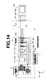
- FIG. 14 is a diagram for explaining a state in which the position of the shifted focal point of the imaging unit is corrected.
- FIG. 15 is a diagram that illustrates a flow chart of processes related to correction of the focal point.
- FIG. 16 is a diagram that illustrates a flow chart of a process that determines an initial position of a stage, denoted as step S 1 in FIG. 15 .
- FIG. 17 is a diagram that illustrates an image which is obtained by the imaging unit when a scan number k is k 0 .
- FIG. 18 is a diagram that illustrates an image which is obtained by the imaging unit when the scan number k is k p .
- FIG. 19 is a diagram that illustrates an image which is obtained by the imaging unit when the scan number k is k max .
- FIG. 20 is a diagram that illustrates an image which is obtained by the imaging unit when the scan number k is k q .
- FIG. 21 is a diagram that illustrates an image which is obtained by the imaging unit when the scan number k is k r .
- FIG. 22 is a diagram for explaining the light intensity of illuminating light, which is detected along a z axis in the image illustrated in FIG. 17 .
- FIG. 23 is a diagram for explaining the light intensity of illuminating light, which is detected along the z axis in the image illustrated in FIG. 18 .
- FIG. 24 is a diagram for explaining the light intensity of illuminating light, which is detected along the z axis in the image illustrated in FIG. 19 .
- FIG. 25 is a diagram for explaining the light intensity of illuminating light, which is detected along the z axis in the image illustrated in FIG. 20 .
- FIG. 26 is a diagram for explaining the light intensity of illuminating light, which is detected along the z axis in the image illustrated in FIG. 21 .
- FIG. 27 is a diagram that illustrates a flow chart of a process that determines a drive amount ⁇ X of a stage, denoted as step S 11 in FIG. 15 .
- FIG. 28 is a diagram for explaining a relationship between an accumulated amount Q of heat energy, which is accumulated within the EUV light generating apparatus, and a position X (Q) of the focal point of the imaging unit.
- FIG. 29 is a diagram for explaining a burst operation, which is performed to obtain a data table that shows a correspondent relationship between accumulated amounts Q i of heat energy and positions X i of the focal point corresponding to the relationship illustrated in FIG. 28 , as well as a discharge time constant ⁇ .
- FIG. 30 is a diagram for explaining an amount of shift ⁇ X sft of the focal point, which shifts due to the burst operation illustrated in FIG. 29 .
- FIG. 31 is a diagram for explaining the data table which is obtained by the burst operation illustrated in FIG. 29 .
- FIG. 32 is a diagram for explaining the configuration of an EUV light generating apparatus according to a third embodiment.
- FIG. 33 is a diagram that illustrates a flow chart of processes related to obtaining the data table illustrated in FIG. 31 and the discharge time constant ⁇ , performed by a control unit.
- FIG. 34 is a diagram that illustrates a flow chart of a process that measures a position X org of a focal point in a state before EUV light is generated, denoted as step S 21 in FIG. 33 .
- FIG. 35 is a diagram that illustrates a flow chart of a process that measures a position X i of a focal point at a power P i , denoted as step S 22 in FIG. 33 .
- FIG. 36 is a diagram that illustrates a flow chart of a process that measures a pulse number N equiv , denoted as step S 224 in FIG. 35 .
- FIG. 37 is a diagram that illustrates a flow chart of a process that confirms whether an amount of shift of a focal point has stabilized, denoted as step S 32 in FIG. 36 .
- FIG. 38 is a diagram that illustrates a flow chart of a process that obtains contrast to measure a position X i , denoted as step S 225 in FIG. 35 .
- FIG. 39 is a diagram that illustrates a flow chart of a process that measures a relaxation time T i , denoted as step S 23 in FIG. 33 .
- FIG. 40 is a diagram that illustrates a flow chart of a process that obtains a contrast and measures a relaxation time T i at a position X i , denoted as step S 235 in FIG. 39 .
- FIG. 41 is a diagram that illustrates a flow chart of a process that obtains the discharge time constant ⁇ , denoted as step S 24 in FIG. 33 .
- FIG. 42 is a diagram for explaining the configurations of the main parts of an EUV light generating apparatus according to a fourth embodiment.
- FIG. 43 is a diagram for explaining the configurations of the main parts of an EUV light generating apparatus according to a fifth embodiment.
- FIG. 44 is a diagram for explaining the configurations of the main parts of an EUV light generating apparatus according to a sixth embodiment.
- FIG. 45 is a diagram for explaining the configurations of the main parts of an EUV light generating apparatus according to a seventh embodiment.
- FIG. 46 is a diagram for explaining the configurations of the main parts of an EUV light generating apparatus according to an eighth embodiment.
- FIG. 47 is a diagram for explaining the configurations of the main parts of an EUV light generating apparatus according to a ninth embodiment.
- FIG. 48 is a block diagram that illustrates the hardware environment of each control unit.
- FIG. 1 is a diagram that schematically illustrates the configuration of an exemplary EUV light generating system of the LPP type.
- An EUV light generating apparatus 1 may be employed with at least one laser apparatus 3 .
- a system that includes the EUV light generating apparatus 1 and the laser apparatus 3 may be referred to as an EUV light generating system 11 .
- the EUV light generating apparatus 1 may include a chamber 2 and a target supply unit 26 .
- the chamber 2 may be capable of being sealed to be gastight.
- the target supply unit 26 may be mounted on the chamber 2 so as to penetrate through a wall of the chamber 2 , for example.
- the material of a target 27 which is supplied by the target supply unit 26 may include, but is not limited to, tin, terbium, gadolinium, lithium, xenon, or any combination of two or more of these substances.
- a wall of the chamber 2 may have at least one aperture penetrating therethrough.
- a window 21 may be provided at the aperture.
- a pulsed laser beam 32 which is output from the laser apparatus 3 may be transmitted through the window 21 .
- An EUV light collecting mirror 23 having a spheroidal reflective surface may be provided in the chamber 2 , for example.
- the EUV light collecting mirror 23 may have a first focal point and a second focal point.
- the surface of the EUV light collecting mirror 23 may have a multi layered reflective film, in which molybdenum layers and silicon layers are alternately laminated, formed thereon, for example.
- the EUV light collecting mirror 23 may be provided such that the first focal point is positioned in a plasma generating region 25 and the second focal point is positioned at an intermediate focal (IF) point 292 , for example.
- the EUV light collecting mirror 23 may have an aperture 24 formed at the center thereof, and a pulsed laser beam 33 may pass through the aperture 24 .
- the EUV light generating apparatus 1 may further include an EUV light generation control unit 5 , a target sensor 4 , etc.
- the target sensor 4 may have an image capturing function and may be configured to detect the presence, the trajectory, the position, the velocity, etc. of the target 27 .
- the EUV light generating apparatus 1 may include a connecting portion 29 that enables the interior of the chamber 2 to be in communication with the interior of an exposure apparatus 6 .
- a wall 291 having an aperture 293 formed therethrough may be provided in the connecting portion 29 .
- the wall 291 may be provided such that the aperture 293 is positioned at the second focal point of the EUV light collecting mirror 23 .
- the EUV light generating apparatus 1 may include a laser beam propagating direction control unit 34 , a laser beam focusing mirror 22 , and a target collector 28 for collecting the target 27 .
- the laser beam propagating direction controlling unit 34 may be equipped with an optical element for regulating the propagating direction of a laser beam, and an actuator for adjusting the position, orientation, etc. of the optical element.
- a pulsed laser beam 31 which is output from the laser apparatus 3 may propagate via the laser beam propagating direction control unit 34 , be transmitted through the window 21 as the pulsed laser beam 32 , and then enter the chamber 2 .
- the pulsed laser beam 32 may propagate through the chamber 2 along at least one laser beam path and be reflected by the laser beam focusing mirror 22 , and at least one target 27 may be irradiated with the laser beam, which is the pulsed laser beam 33 .
- the target supply unit 26 may be configured to output the target 27 toward the plasma generating region 25 in the interior of the chamber 2 .
- the target 27 may be irradiated with at least one pulse which is included in the pulsed laser beam 33 .
- the target 27 which is irradiated with the pulsed laser beam 33 may turn into plasma, and EUV light 251 may be emitted from the plasma along with light having other wavelengths.
- the EUV light 251 may be selectively reflected by the EUV light collecting mirror 23 .
- EUV light 252 which is reflected by the EUV light collecting mirror 23 may be focused at the intermediate focal point 292 , and output to the exposure apparatus 6 .
- a single target 27 may be irradiated with a plurality of pulses which are included in the pulsed laser beam 33 .
- a “target” refers to a substance which is introduced into a chamber and is irradiated with a laser beam.
- the target which is irradiated with the laser beam turns into plasma and emits EUV light.
- a “droplet” refers to one form in which the target is supplied into the chamber.
- a “plasma generating region” refers to a predetermined region within the chamber.
- the plasma generating region is a region in which the target which is output into the chamber is irradiated with the laser beam, and the target turns into plasma.
- a “droplet trajectory” is a path that a droplet which is output to the interior of the chamber travels along.
- the droplet trajectory may intersect the optical path of the laser beam which is introduced to the interior of the chamber, at the plasma generating region.
- An “axis of an optical path” refers to an axis that passes through the center of the cross section of a light beam along the direction in which the light propagates.
- optical path refers to a path through which light passes.
- the optical path may include the axis of the optical path.
- a “Z axis direction” is a direction in which the EUV light generating apparatus outputs EUV light. That is, the Z axis direction is the direction in which EUV light is output from the chamber of the EUV light generating apparatus to the exposure apparatus.
- a “Y axis direction” is a direction in which the target supply unit outputs the target to the interior of the chamber.
- An “X axis direction” is a direction that perpendicularly intersects the Y axis direction and the Z axis direction.
- An EUV light generating apparatus 1 of a comparative example will be described with reference to FIG. 2 through FIG. 10 .
- the EUV light generating apparatus 1 of the comparative example may be an EUV light generating apparatus 1 that includes an image measuring unit 45 .
- FIG. 2 is a diagram for explaining the configuration of the EUV light generating apparatus 1 of the comparative example.
- the chamber 2 may be a container into which a droplet 271 is supplied by the target supply unit 26 and within which the droplet 271 is irradiated with the pulsed laser beam 33 to generate plasma and to generate the EUV light 252 .
- a wall 2 a of the chamber 2 may form an interior space of the chamber 2 and partition the interior space of the chamber 2 from the exterior.
- the laser beam propagating direction control unit 34 may control the propagating direction of the pulsed laser beam 31 such that the pulsed laser beam 31 which is output from the laser apparatus 3 is transmitted through the window 21 as the pulsed laser beam 32 .
- the operation of the laser beam propagating direction control unit 34 may be controlled by the EUV light generation control unit 5 .
- the beam splitter 341 may transmit a portion of the pulsed laser beam 31 toward the second light energy measuring unit 8 , and may reflect another portion of the pulsed laser beam 31 toward the mirror 342 .
- the beam splitter 341 may be included within the laser beam propagating direction control unit 34 .
- the mirror 342 may be provided along the optical path of the pulsed laser beam 31 which is reflected by the beam splitter 341 .
- the mirror 342 may be included within the laser beam propagating direction control unit 34 .
- the laser beam focusing mirror 22 may reflect the pulsed laser beam 32 , which is transmitted through the window 21 , toward the plasma generating region 25 .
- the laser beam focusing mirror 22 may focus the reflected pulsed laser beam 32 in the plasma generating region 25 as the pulsed laser beam 33 .
- the laser beam focusing mirror 22 may be mounted on a stage, which is not illustrated, that adjusts the position and the orientation thereof.
- the target supply unit 26 may be a device that melts the target 27 to be supplied to the interior of the chamber 2 , and outputs the target 27 toward the plasma generating region 25 in the interior of the chamber 2 as the droplet 271 .
- the target supply unit 26 may be a device that outputs the droplet 271 by the so called continuous jet method.
- the target 27 which is supplied by the target supply unit 26 may be formed by a metal material.
- the metal material that forms the target 27 may be tin, terbium, gadolinium, or any combination including two or more thereof.
- the metal material that forms the target 27 may be tin.
- the target supply unit 26 may be provided on the wall 2 a of the chamber 2 .
- the operation of the target supply unit 26 may be controlled by the control unit 51 .
- the target collector 28 may be a device that collects droplets 271 which are not irradiated with the pulsed laser beam 33 , from among the droplets 271 which are output to the interior of the chamber 2 .
- the target collector 28 may be provided on the wall 2 a of the chamber 2 along a line that extends from a droplet trajectory T.
- the droplet detector 41 may be a detector that detects the droplet 271 which is output to the interior of the chamber 2 .
- the droplet detector 41 may be a detector that detects a timing at which the droplet 271 passes through a predetermined detection region R, which is at a predetermined position in the interior of the chamber 2 .
- the predetermined position at which the detection region R is located may be a position along the droplet trajectory T between the target supply unit 26 and the plasma generating region 25 .
- the droplet detector 41 may include an illuminating unit 410 , a light receiving unit 430 , a window 414 , and a window 434 .
- the illuminating unit 410 and the light receiving unit 430 may respectively be connected to the wall 2 a of the chamber 2 via the window 414 and the window 434 .
- the illuminating unit 410 and the light receiving unit 430 may be arranged such that they face each other with the detection region R along the droplet trajectory T interposed therebetween.
- the direction along which the illuminating unit 410 and the light receiving unit 430 face each other may substantially perpendicularly intersect the droplet trajectory T.
- the illuminating unit 410 may output illuminating light to the detection region R in the interior of the chamber 2 .
- the illuminating unit 410 may include a light source 411 , an illuminating optical system 412 , and an optical filter 413 .
- the light source 411 may be a light source that outputs illuminating light so as to illuminate the droplet 271 that passes through the detection region R.
- the light source 411 may be constituted by a light source that outputs continuous light of a single wavelength, such as a CW (Continuous Wave) laser.
- the light source 411 may be constituted by a light source that continuously outputs pulsed light.
- the illuminating optical system 412 may be an optical system that includes a focusing lens and the like.
- the focusing lens may be a cylindrical lens, for example.
- the illuminating optical system 412 may transmit the illuminating light which is output from the light source 411 , and guide the transmitted illuminating light to the optical filter 413 .
- the illuminating optical system 412 may shape and focus the illuminating light, which is output from the light source 411 , at the detection region R, via the optical filter 413 and the window 414 .
- the optical filter 413 may be a bandpass filter having a high transmissivity with respect to the wavelength of the illuminating light which is output from the light source.
- the optical filter 413 may be provided along an optical path of the illuminating light which is transmitted through the illuminating optical system 412 .
- the optical filter 413 may transit the illuminating light, which is transmitted through the illuminating optical system 412 , toward the window 414 .
- the optical filter 413 may prevent the light which is emitted from the plasma from entering the light source 411 via the illuminating optical system 412 .
- the window 414 may transmit the illuminating light, which is transmitted through the optical filter 413 , toward the detection region R.
- the light receiving unit 430 may include a light sensor 431 , a light receiving optical system 432 , an optical filter 433 , and a signal processing unit 435 .
- the window 434 may be provided in the wall 2 a of the chamber 2 .
- the window 434 may be mounted in the wall 2 a via a sealing member, which is not illustrated, such that the pressure in the interior of the chamber 2 is maintained at a pressure approximating a vacuum.
- the window 434 may be arranged to face the detection region R.
- the window 434 may be arranged to face the window 414 with the detection region R interposed therebetween.
- the window 434 may transmit the illuminating light, which is output to the detection region R, toward the optical filter 433 .
- the optical filter 433 may be an optical filter having a high transmissivity with respect to the wavelength of the illuminating light which is output from the light source 411 , and a low transmissivity with respect to many of the wavelengths of light which is emitted from the plasma.
- the optical filter 433 may be a bandpass filter having a high transmissivity with respect to the wavelength of the illuminating light which is output from the light source 411 .
- the optical filter 433 may be provided along an optical path of the illuminating light which is transmitted through the window 434 .
- the light receiving optical system 432 may transmit the illuminating light, which is transmitted through the optical filter 433 , and guide the transmitted illuminating light toward the light sensor 431 .
- the light receiving optical system 432 may shape the illuminating light which is transmitted through the optical filter 433 and guide the shaped illuminating light to a detecting surface of the light sensor 431 .
- the light receiving optical system 432 may form an image of the illuminating light, which is output to the detection region R, at the detection region R, on the detecting surface of the light sensor 431 .
- the light sensor 431 may detect the droplet 271 that passes through the detection region R, by detecting the illuminating light, which is output so as to illuminate the droplet 271 that passes through the detection region R.
- the light sensor 431 may be constituted by including detecting elements such as a photodiode array, a photomultiplier, and a multi pixel photocounter.
- the light sensor 431 may be provided along an optical path of the illuminating light which is transmitted through the light receiving optical system 432 .
- the signal processing unit 435 may generate a droplet detection signal at a timing at which the detection signal from the light sensor 431 becomes lower than a predetermined threshold value.
- the image measuring unit 45 may be a measuring device that captures an image of the droplet 271 which is supplied to the plasma generating region 25 , and measures the state of the droplet 271 supplied to the plasma generating region 25 .
- the image measuring unit 45 may include an illuminating unit 450 , an imaging unit 470 , a window 454 , and a window 474 .
- the illuminating unit 450 and the imaging unit 470 may be arranged such that they face each other with the plasma generating region 25 interposed therebetween.
- the direction along which the illuminating unit 450 and the imaging unit 470 face each other may substantially perpendicularly intersect the droplet trajectory T.
- the illuminating unit 450 may include a light source 451 and an illuminating optical system 452 .
- the light source 451 may be constituted by a light source that outputs pulsed light, such as a flash lamp and a laser.
- the operation of the light source 451 may be controlled by the control unit 51 .
- the imaging unit 470 may capture an image of the plasma generating region 25 .
- the imaging unit 470 may capture an image of the droplet 271 supplied to the plasma generating region 25 .
- the window 474 may be provided in the wall 2 a of the chamber 2 .
- the window 474 may be mounted in the wall 2 a of the chamber 2 via a sealing member, which is not illustrated, such that the pressure in the interior of the chamber 2 is maintained at a pressure approximating a vacuum.
- window 474 may be included in the imaging unit 470 .
- the optical filter 473 may be an optical filter having a high transmissivity with respect to the wavelength of the illuminating light which is output from the light source 451 , and a low transmissivity with respect to many of the wavelengths of light which is emitted from the plasma.
- the optical filter 473 may be a notch filter having a low transmissivity with respect to many of the wavelengths of the light which is emitted from the plasma.
- the optical filter 473 may transmit the illuminating light, which is transmitted through the window 474 , toward the image forming optical system 472 .
- the optical filter 473 may prevent the light which is emitted from the plasma from entering the image sensor 471 via the image forming optical system 472 , the optical shutter 475 , and the transfer optical system 476 .
- the image forming optical system 472 may be constituted by an optical system in which a plurality of lenses is combined.
- the image forming optical system 472 may be provided along an optical path of the illuminating light which is transmitted through the optical filter 473 .
- the image forming optical system 472 may be provided remote from the window 474 .
- the image forming optical system 472 may be arranged such that the focal point of the lens thereof positioned most toward the plasma generating region 25 is at the plasma generating region 25 .
- the image forming optical system 472 may be arranged such that the focal point of a lens thereof positioned at the side of the plasma generating region 25 is at the position of the droplet 271 supplied to the plasma generating region 25 .
- the above focal point will be referred to as focal point F hereinafter.
- the optical shutter 475 may be provided along an optical path of the illuminating light which is transmitted through the image forming optical system 472 .
- the optical shutter 475 may suppress the passage therethrough of the illuminating light, which is transmitted through the image forming optical system 472 .
- the operation of the optical shutter 475 may be controlled by the control unit 51 .
- the transfer optical system 476 may transmit the illuminating light that passes through the optical shutter 475 , and guide the illuminating light to the image sensor 471 .
- the transfer optical system 476 may transfer the image of the illuminating light at the plasma generating region 25 , which is formed on the surface of the optical shutter 475 at the light output side, onto a detecting surface of the image sensor 471 .
- the image sensor 471 may be constituted by including a detecting element such as a CCD (Charge-Coupled Device).
- a detecting element such as a CCD (Charge-Coupled Device).
- the energy of the EUV light 251 which is emitted from the plasma may be light energy which is generated in the EUV light generating apparatus 1 when the EUV light 251 is generated.
- the first light energy measuring unit 7 may include an EUV energy sensor 71 , an optical filter 72 , a mirror 73 , and a pinhole plate 74 .
- the pinhole plate 74 may be arranged to face the plasma generating region 25 .
- the aperture of the pinhole plate 74 may cause the light which is emitted from the plasma to pass therethrough toward the mirror 73 .
- the mirror 73 may be configured to have a high reflectance with respect to the wavelength of the EUV light 251 .
- a reflective surface of the mirror 73 may be formed by a multilayered film formed by molybdenum and silicon.
- the mirror 73 may reflect light that includes the EUV light 251 from the light that passes through the aperture of the pinhole plate 74 toward the optical filter 72 .
- the optical filter 72 may be an optical filter formed by a thin zirconium film or a thin zirconium film that includes silicon.
- the optical filter 72 may transmit the EUV light 251 , which is included in the light reflected by the mirror 73 , toward the EUV energy sensor 71 .
- the optical filter 72 may prevent light included in the light reflected by the mirror 73 having wavelengths different from that of the EUV light 251 from entering the EUV energy sensor 71 .
- the EUV energy sensor 71 may be a light sensor that measures the energy of the EUV light 251 .
- the EUV energy sensor 71 may be provided along an optical path of the EUV light 251 which is transmitted through the optical filter 72 .
- the EUV energy sensor 71 may detect the energy of the EUV light 251 which is transmitted through the optical filter 72 , and estimate the energy of the EUV light 251 which is emitted from the plasma based on the detected value. The EUV energy sensor 71 may designate this estimated value as the measured value of the energy of the EUV light 251 which is emitted from the plasma. The EUV energy sensor 71 may send an EUV energy measurement signal that includes this measured value to the control unit 51 .
- the respective energies of the pulsed laser beams 31 through 33 may be light energy which is generated in the EUV light generating apparatus 1 when the EUV light 251 is generated.
- the laser energy sensor 81 may be constituted by including a detecting element having a high sensitivity with respect to the wavelength of the pulsed laser beam 31 .
- the laser energy sensor 81 may be provided along an optical path of the pulsed laser beam 31 which is transmitted through the beam splitter 341 .
- the laser energy sensor 81 may detect the energy of the pulsed laser beam 31 which is transmitted through the beam splitter 341 , and estimate the energy of the pulsed laser beam 33 with which the droplet 271 is irradiated based on the detected value. The laser energy sensor 81 may designate this estimated value as the measured value of the pulsed laser beam 33 with which the droplet 271 is irradiated. The laser energy sensor 81 may send a laser energy measurement signal that includes this measured value to the control unit 51 .
- the laser energy sensor 81 may detect the energy of one of the pulsed laser beams 31 through 33 .
- the beam splitter 341 may be provided along the optical path of one of the pulsed laser beams 31 through 33 to be detected by the laser energy sensor 81 .
- the EUV light generation control unit 5 may send and receive various signals to and from the exposure apparatus 6 .
- the EUV light generation control unit 5 may totally control the operations of the constituent elements of the EUV light generating system 11 , based on various signals which are received from the exposure apparatus 6 .
- the EUV light generation control unit 5 may send and receive various signals to and from the laser apparatus 3 .
- the EUV light generation control unit 5 may send and receive various signals to and from the laser beam propagating direction control unit 34 as well as to and from the stage on which the laser beam focusing mirror 22 is mounted. Thereby, the EUV light generation control unit 5 may control the propagating directions and the focusing positions of the pulsed laser beams 31 through 33 .
- the EUV light generation control unit 5 may send and receive various signals to and from control unit 51 .
- the EUV light generation control unit 51 may receive signals that include data related to the droplet 271 , the pulsed laser beam 31 , and the EUV light 251 from the control unit 51 .
- the EUV light generation control unit 5 may send signals that include various control commands to the control unit 51 , such that the EUV light 252 is stably output.
- the EUV light generation control unit 5 may indirectly control the operations of the constituent elements which are included in the target supply unit 26 , the droplet detector 41 , the image measuring unit 45 , the first light energy measuring unit 7 , and the second light energy measuring unit 8 .
- the control unit 51 may send and receive various signals to and from the constituent elements of the EUV light generating apparatus 1 .
- the control unit 51 may control the operations of the constituent elements which are included in the droplet detector 41 , the image measuring unit 45 , the first light energy measuring unit 7 , and the second light energy measuring unit 8 , based on control commands received from the EUV light generation control unit 5 .
- the control unit 51 may include a delay circuit 511 for controlling the operational timings of the constituent elements which are included in the image measuring unit 45 and the laser apparatus 3 .
- the target supply unit 26 may output the droplet 271 toward the plasma generating region 25 in the interior of the chamber 2 , according to a control command from the control unit 51 .
- the droplet 271 which is output to the interior of the chamber 2 may travel along the droplet trajectory T, and pass through the detection region R.
- the light source 411 of the droplet detector 41 may output the illuminating light to the detection region R according to a control command from the control unit 51 so as to illuminate the droplet 271 that passes through the detection region R.
- the light sensor 431 may detect the illuminating light which is output to the detection region R.
- a portion of the illuminating light which is output from the light source 411 may be shielded by the droplet 271 that passes through the detection region R.
- the light intensity of the illuminating light which is detected by the light sensor 431 will significantly decrease compared to a case in which the droplet 271 is not passing through the detection region R.
- the light sensor 431 may generate the detection signal corresponding to the change in the light intensity of the detected illuminating light, and may send the detection signal to the signal processing unit 435 .
- the signal processing unit 435 may generate the droplet detection signal based on the detection signal which is sent from the light sensor 431 , and send the droplet detection signal to the control unit 51 .
- the control unit 51 may add a first delay time to a timing at which the droplet detection signal is received by employing the delay circuit 511 .
- the control unit 51 may send an illumination trigger signal to the light source 451 of the image measuring unit 45 at a timing, which is delayed from the timing at which the droplet detection signal is received by the first delay time.
- the illumination trigger signal may be a signal that provides momentum to the light source 451 to output the illuminating light.
- the first delay time may be an amount of time that causes the timing at which the illuminating light from the light source 451 enters the plasma generating region 25 and the timing at which the droplet 271 reaches the plasma generating region 25 to substantially match.
- the control unit 51 may add a second delay time to the timing at which the droplet detection signal is received by employing the delay circuit 511 .
- the control unit 51 may send a shutter trigger signal to the optical shutter 475 of the image measuring unit 45 at a timing, which is delayed from the timing at which the droplet detection signal is received by the second delay time.
- the second delay time may be an amount of time that causes the timing at which the optical shutter 475 transitions to the open state and the timing at which illuminating light from the light source 451 enters the optical shutter 475 to substantially match.
- the control unit 51 may add a third delay time to the timing at which the droplet detection signal is received by employing the delay circuit 511 .
- the control unit 51 may send a measurement trigger signal to the image sensor 471 of the image measuring unit 45 at a timing, which is delayed from the timing at which the droplet detection signal is received by the third delay time.
- the measurement trigger signal may be a signal that provides momentum to the image sensor 471 to be exposed to the illuminating light and to obtain an image thereof.
- the third delay time may be an amount of time that causes the timing at which the image sensor 471 is exposed to the illuminating light and obtains an image thereof, and the timing at which illuminating light from the light source 451 enters the image sensor 471 , to substantially match.
- the control unit 51 may add a fourth delay time to the timing at which the droplet detection signal is received by employing the delay circuit 511 .
- the control unit 51 may send a laser trigger signal to the laser apparatus 3 at a timing, which is delayed from the timing at which the droplet detection signal is received by the fourth delay time.
- the fourth delay time may be an amount of time that causes the timing at which the pulsed laser beam 33 is focused at the plasma generating region 25 and the timing at which the droplet 271 reaches the plasma generating region 25 to substantially match.
- the first through fourth delay times may be stored in the control unit 51 in advance.
- the light source 451 of the image measuring unit 45 may output the illuminating light to the plasma generating region 25 so as to illuminate the droplet 271 supplied to the plasma generating region 25 .
- the optical shutter 475 When the optical shutter 475 receives the shutter trigger signal, the optical shutter 475 may transition to the open state, and pass the illuminating light which is output to the plasma generating region 25 therethrough.
- a portion of the illuminating light which is output to the plasma generating region 25 may be shielded by illuminating the droplet 271 .
- a portion of the image of the illuminating light at the plasma generating region 25 may be transferred to the image sensor 471 as an image of a shadow of the droplet 271 .
- the image of the illuminating light which is obtained by the image sensor 471 may include the image of the shadow of the droplet 271 .
- the image sensor 471 may generate image data corresponding to the obtained image, and send the image measurement signal that includes the generated image data to the control unit 51 .
- the image sensor 471 may measure the state of the droplet 271 from the generated image data, include the measured value in the image measurement signal, and send the image measurement signal to the control unit 51 .
- the laser apparatus 3 may output the pulsed laser beam 31 .
- a portion of the pulsed laser beam 31 which is output from the laser apparatus 3 may be transmitted through the beam splitter 341 and enter the laser energy sensor 81 of the second light energy measuring unit 8 .
- the laser energy sensor 81 may measure the energy of the input pulsed laser beam 31 , and send the laser energy measurement signal that includes the measured value to the control unit 51 .
- pulsed laser beam 31 which is output from the laser apparatus 3 may be reflected by the beam splitter 341 , and enter the interior of the chamber 2 via the mirror 342 and the window 21 as the pulsed laser beam 32 .
- the pulsed laser beam 32 which is introduced to the interior of the chamber 2 may be focused by the laser beam focusing mirror 22 , and be guided to the plasma generating region 25 as the pulsed laser beam 33 .
- the pulsed laser beam 33 may be guided to the plasma generating region 25 at the timing at which the droplet 271 reaches the plasma generating region 25 .
- the EUV energy sensor 71 may measure the energy of the input EUV light 251 , and send the EUV energy measurement signal that includes the measured value to the control unit 51 .
- FIG. 3 is a diagram for explaining a problem of the EUV light generating apparatus 1 of the comparative example.
- the EUV light generating apparatus 1 may generate the EUV light 251 by the droplet 271 supplied to the plasma generating region 25 being irradiated with the pulsed laser beam 33 , thereby turning the droplet 271 into plasma.
- the droplet 271 When the droplet 271 turns into plasma, light having various wavelengths, such as the EUV light 251 , DUV (Deep Ultraviolet) light, UV (Ultraviolet) light, visible light, and infrared light, may be radiated.
- fine particles such as atoms, clusters, and ions of the target 27 may be radiated. Energy is imparted to the fine particles which are emitted from the plasma by the pulsed laser beam 33 , and therefore the fine particles may have a high amount of kinetic energy.
- the light, fine particles, and the like which are emitted from the plasma may enter the wall 2 a of the chamber 2 in the vicinity of the plasma generating region 25 and the image measuring unit 45 , and may heat the wall 2 a of the chamber 2 and the image measuring unit 45 . That is, the energy of the light which is emitted from the plasma is light energy which is generated when the EUV light 251 is generated. The light energy may be converted into heat energy within the EUV light generating apparatus 1 , and heat the EUV light generating apparatus 1 that includes the wall 2 a of the chamber 2 and the image measuring unit 45 . Similarly, the kinetic energy of the fine particles which are emitted from the plasma may be converted into heat energy within the EUV light generating apparatus 1 , and heat the EUV light generating apparatus 1 .
- the imaging unit 470 which is included in the image measuring unit 45 is arranged such that it is capable of obtaining an image of the droplet 271 in focus when the focal point F matches the position of the droplet 271 , as an example.
- this focal point F is the focal point of the lens of the image forming optical system 472 positioned most toward the side of the droplet 271 , as described previously.
- the imaging unit 470 may obtain images which are out of focus. Therefore, there may be cases in which the image measuring unit 45 cannot appropriately measure the state of the droplet 271 supplied to the plasma generating region 25 .
- FIG. 4 is a diagram for explaining an initial state of an imaging unit 470 of the comparative example.
- the initial state may be a state prior to the generation of the EUV light 251 being performed.
- the initial state may be a state prior to the light, the fine particles, etc. which are emitted from the plasma entering the wall 2 a of the chamber 2 and the image measuring unit 45 .
- FIG. 5 is a diagram that illustrates an image of the droplet 271 which is obtained by the imaging unit 470 in the state illustrated in FIG. 4 .
- FIG. 6 is a diagram for explaining a state in which the focal point F of the imaging unit 470 of the comparative example is shifted due to a thermal lens effect and thermal deformation of the window 474 .
- FIG. 7 is a diagram for explaining a state in which the focal point F of the imaging unit 470 of the comparative example is shifted due to a thermal lens effect and thermal deformation of the image forming optical system 472 .
- FIG. 8 is a diagram for explaining a state in which the focal point F of the imaging unit 470 of the comparative example is shifted due to a thermal lens effect being generated in the environment of the image forming optical system 472 .
- FIG. 6 is a diagram for explaining a state in which the focal point F of the imaging unit 470 of the comparative example is shifted due to a thermal lens effect and thermal deformation of the window 474 .
- FIG. 7 is a diagram for explaining a state in which the focal point F of the imaging unit 470 of the comparative example is shifted due to a thermal
- FIG. 9 is a diagram for explaining a state in which the focal point F of the imaging unit 470 of the comparative example is shifted due to thermal deformation of the wall 2 a of the chamber 2 .
- FIG. 10 is a diagram that illustrates an image of the droplet 271 which is obtained by the imaging unit 470 of the comparative example in the state illustrated in at least one of FIG. 6 through FIG. 9 .
- the focal point F of the imaging unit 470 may be adjusted in advance so as to match the position of the droplet 271 supplied to the plasma generating region 25 in the initial state.
- reference numeral 472 a denotes an image formation plane of the image forming optical system 472 that constitutes the imaging unit 470 .
- reference numeral 475 a denotes a light receiving surface of the optical shutter 475
- reference numeral 475 b denotes a reproduction surface of the optical shutter 475
- reference numeral 471 a denotes an imaging surface of the image sensor 471 .
- the image formation plane 472 a of the image forming optical system 472 matches the light receiving surface 475 a of the optical shutter 475 . Therefore, an image of the droplet 271 in focus may be detected by the optical shutter 475 , and the same image may be reproduced and output on the reproduction surface 475 b of the optical shutter 475 .
- the output image may be formed on the imaging surface 471 a of the image sensor 471 by the transfer optical system 476 .
- the image of the droplet 271 in focus may ultimately be captured by the image sensor 471 in this manner.
- the image of the droplet 271 which is obtained by the imaging unit 470 may have high contrast, as illustrated in FIG. 5 .
- high contrast may refer to a level of contrast which is sufficiently high to a degree that enables the outline of the droplet 271 to be specified and the state of the droplet 271 to be appropriately measured.
- Low contrast may refer to a level of contrast which is low to a degree that does not enable the outline of the droplet 271 to be specified and the state of the droplet 271 to be appropriately measured.
- the light, the fine particles, etc. which are emitted from the plasma may enter the wall 2 a of the chamber 2 and the image measuring unit 45 , and heat these components.
- focal point F of the imaging unit 470 shifts due to the phenomena listed under (1) through (4) below occurring either singly or in combination.
- a thermal lens effect and thermal deformation occur at the window 474 , as illustrated in FIG. 6 . That is, a temperature distribution is generated in the window 474 due to being heated, and therefore it may be considered that a refractive index distribution will be generated. In addition, it may be considered that the window 474 undergoes thermal deformation due to being heated, and therefore it may be considered that the length of a path that the illuminating light passes through will change.
- the optical path length of the illuminating light that travels between the plasma generating region 25 and the imaging unit 470 may change.
- the focal length of the imaging unit 470 may be effectively shortened due to being heated.
- the focal point F of the imaging unit 470 may shift from the plasma generating region 25 toward the imaging unit 470 due to being heated.
- the optical path length may be the product of the length and the refractive index of a medium through which light passes.
- FIG. 6 illustrates a state in which the image formation plane 472 a of the image forming optical system 472 for the droplet 271 does not match the light receiving surface 475 a of the optical shutter 475 .
- the image of the droplet 271 which is captured by the mage sensor 471 may be that which is not in focus.
- FIG. 7 illustrates an example of a case in which a thermal lens effect and thermal deformation occur in a lens of the image forming optical system 472 positioned at the side of the plasma generating region 25 . That is, a temperature distribution is generated in the lens of the image forming optical system 472 positioned at the side of the plasma generating region 25 due to being heated, and therefore it may be considered that a refractive index distribution will be generated. In addition, it may be considered that the lens undergoes thermal deformation due to being heated, and therefore it may be considered that the length of a path through which the illuminating light passes will change.
- the optical path length of the illuminating light that travels through the imaging unit 470 may change.
- the focal length of the lens of the image forming optical system 472 positioned at the side of the plasma generating region 25 may be effectively shortened due to being heated.
- the focal point F of the imaging unit 470 may shift from the plasma generating region 25 toward the imaging unit 470 due to being heated.
- thermo lens effect is generated in the environment in the periphery of the image forming optical system 472 , as illustrated in FIG. 8 . That is, a temperature distribution is generated in the gas in the periphery of the image forming optical system 472 due to being heated, and therefore it may be considered that a refractive index distribution will be generated.
- the optical path length of the illuminating light that travels through the imaging unit 470 may change.
- the focal length of the imaging unit 470 may be effectively shortened due to being heated.
- the focal point F of the imaging unit 470 may shift from the plasma generating region 25 toward the imaging unit 470 due to being heated.
- thermal deformation of the wall 2 a of the chamber 2 will occur, as illustrated in FIG. 9 . That is, the wall 2 a of the chamber 2 undergoes thermal deformation due to being heated, and therefore it may be considered that the position of the imaging unit 470 which is provided on the wall 2 a will change. In other words, the wall 2 a undergoes thermal deformation, and therefore it may be considered that the physical distance between the imaging unit 470 which is provided on the wall 2 a via the window 474 and the plasma generating region 25 will change.
- the optical path length of the illuminating light that travels between the plasma generating region 25 and the imaging unit 470 may change.
- the focal length of the imaging unit 470 may be effectively shortened due to being heated.
- the focal point F of the imaging unit 470 may shift from the plasma generating region 25 toward the imaging unit 470 due to being heated.
- the image of the droplet 271 which is obtained by the imaging unit 470 may be an image having low contrast and is out of focus, as illustrated in FIG. 10 .
- the image measuring unit 45 may not be capable of appropriately measuring the state of the droplet 271 supplied to the plasma generating region 25 .
- a technique is desired that enables the state of the droplet 271 supplied to the plasma generating region 25 to be appropriately measured even if the focal point F of the imaging unit 470 shifts when the EUV light 251 is generated.
- An EUV light generating apparatus 1 will be described with reference to FIG. 11 through FIG. 31 .
- the EUV light generating apparatus 1 of the first embodiment may be the EUV light generating apparatus 1 of the comparative example, to which a moving mechanism 48 and a stage driving unit 512 are added.
- FIG. 11 is a diagram for explaining the configuration of an EUV light generating apparatus 1 according to the first embodiment.
- the imaging unit 470 may be mounted on the moving mechanism 48 of the first embodiment.
- the moving mechanism 48 may be a mechanism that moves the position of the imaging unit 470 .
- the moving mechanism 48 may move the imaging unit 470 along the axis of the optical path of the illuminating light which is output to the plasma generating region 25 .
- the moving mechanism 48 may be provided in the interior of an optical path pipe, which is not illustrated, that houses the constituent elements of the imaging unit 470 .
- the moving mechanism 48 may include a holder 481 , a plate 482 , and a stage 483 .
- the holder 481 may hold the imaging unit 470 . Specifically, the holder 481 may hold the image sensor 471 , the image forming optical system 472 , the optical filter 473 , the optical shutter 475 , and the transfer optical system 476 included in the imaging unit 470 , without changing the relative positions among these elements.
- the holder 481 may be fixed on the plate 482 .
- the imaging unit 470 may be mounted on the plate 482 via the holder 481 .
- the plate 482 may be connected to the stage 483 .
- the plate 482 may be configured to be movable by the stage 483 .
- the stage 483 may move the position of the imaging unit 470 , which is mounted on the plate 482 , by moving the position of the plate 482 .
- the stage driving unit 512 may be connected to the stage 483 and the control unit 51 .
- FIG. 12 is a diagram for explaining an initial state of the imaging unit 470 of the first embodiment.
- FIG. 13 is a diagram for explaining a state in which the focal point F of the imaging unit 470 is shifted when EUV light 251 is generated.
- FIG. 14 is a diagram for explaining a state in which the position of the shifted focal point F of the imaging unit is corrected.
- the focal point F of the imaging unit 470 of the first embodiment may be adjusted in advance so as to match the position of the droplet 271 supplied to the plasma generating region 25 in the initial state, in the same manner as the imaging unit 470 of the comparative example.
- the imaging unit 470 which is adjusted in this manner as an example may obtain an image of the droplet 271 which is in focus.
- the wall 2 a of the chamber 2 and the image measuring unit 45 may be heated by light, fine articles, etc. which are emitted from the plasma.
- the focal point F of the imaging unit 470 may shift from the plasma generating region 25 toward the side of the imaging unit 470 due to the phenomena listed above as (1) through (4) occurring either singly or in combination, as illustrated in FIG. 13 .
- the control unit 51 may control the stage 483 such that the focal point F of the imaging unit 470 matches the position of the droplet 271 supplied to the plasma generating region 25 , based on the measured value.
- the control unit 51 may correct the position of the shifted focal point F by controlling the stage 483 via the stage driving unit 512 in this manner.
- Steps S 1 and S 2 may be processes which are performed in a preparatory step prior to the EUV light 251 being generated.
- Steps S 3 through S 15 may be processes which are performed at a step in which the EUV light 251 is being generated.
- control unit 51 may determine an initial position X org of the stage 483 .
- the control unit 51 may determine the initial position X org of the stage 483 such that the focal point F of the imaging unit 470 matches the position of the droplet 271 supplied to the plasma generating region 25 .
- the control period ⁇ t may be a period during which the control unit 51 controls the stage 483 , and may be stored in the control unit 51 in advance.
- control unit 51 may initialize parameters related to control of the stage 483 .
- control unit 51 may initialize a timer T t , a pulse number n, a control number m and an integrated value E s of EUV energy E n as expressed by Formula 1.
- timer T t may measure an amount of time that elapses after the control period ⁇ t is initiated.
- the pulse number n may be the number of times that the EUV light 251 is generated after the control period ⁇ t is initiated.
- the control number m may be the number of times that the stage 483 is controlled.
- the EUV energy E n may be the pulse energy of the n th EUV light 251 which is generated after the control period ⁇ t is initiated.
- the EUV energy E n may be the light energy which is generated within the EUV light generating apparatus 1 when the n th EUV light 251 is generated after the control period ⁇ t is initiated.
- the integrated value E s of EUV energy E n may be a value obtained by integrating the pulse energy of the EUV light 251 which is generated from a point in time at which the control period ⁇ t is initiated to a point in time at which the control period ⁇ t is completed.
- the integrated value E s of EUV energy E n may be the light energy which is generated within the EUV light generating apparatus 1 during the control period ⁇ t.
- control unit 51 may judge whether the EUV light 251 is being generated.
- the control unit 51 may judge that the EUV light 251 is not being generated if the EUV energy measurement signal from the first light energy measuring unit 7 is not received, and the process may proceed to step S 8 . In contrast, if the EUV energy measurement signal is received, the control unit 51 may judge that the EUV light 251 is being generated, and the process may proceed to step S 6 .
- control unit 51 may incrementally increase the pulse number n as expressed by Formula 2.
- n n+ 1 [Formula 2]
- control unit may obtain the EUV energy E n .
- the control unit 51 may obtain the measured value of the energy of the EUV light 251 , which is included in the EUV energy measurement signal received at step S 5 , as the EUV energy E n .
- control unit 51 may judge whether the control period ⁇ t has elapsed by employing Formula 3.
- T t ⁇ t [Formula 3]
- the control unit 51 may judge that the control period ⁇ t has not elapsed if the value of the timer T t is not greater than or equal to the control period ⁇ t, and the process may return to step S 5 . In contrast, the control unit 51 may judge that the control period ⁇ t has elapsed if the value of the timer T t is greater than or equal to the control period ⁇ t, and the process may proceed to step S 9 .
- control unit 51 may cease the measurement of time by the timer T t .
- control unit 51 may employ Formula 4 to calculate the integrated value E s of the EUV energy E n .
- control unit 51 may determine the driving amount ⁇ X of the stage 483 .
- the control unit 51 may drive the stage 483 for the driving amount ⁇ X. Thereby, the control unit 51 may correct a position X of the stage 483 as expressed by Formula 5. As a result, the position of the imaging unit 470 will be corrected, and the position of the focal point F may also be corrected.
- X X+ ⁇ Xl [Formula 5]
- control unit 51 may judge whether the contrast of the image of the droplet 271 is within a predetermined allowable range.
- the control unit 51 may control the image measuring unit 45 so as to capture an image of the droplet 271 supplied to the plasma generating region 25 at the position X of the stage 483 , which was corrected at step S 12 .
- control unit 51 may judge whether the contrast of the image of the droplet 271 is within a predetermined allowable range.
- the allowable range may be a range within which the state of the droplet 271 is capable of being measured from the obtained image of the droplet 271 .
- the control unit 51 may proceed to the process of step S 15 if the contrast is within the allowable range. In contrast, if the contrast is not within the allowable range, the control unit 51 may proceed to the process of step S 14 .
- control unit 51 may incrementally increase the control number m as expressed by Formula 6. Then, the control unit 51 may return to the process of step S 3 .
- m m+ 1 [Formula 6]
- control unit 51 may cease control of the stage 483 , and end the present process.
- FIG. 16 is a diagram that illustrates a flow chart of the process that determines the initial position X org of the stage 483 , denoted as step S 1 in FIG. 15 .
- control unit 51 may set parameters related to determining the initial position X org of the stage 483 .
- control unit 51 may set a maximum value X max and a minimum value X min for the position X of the stage 483 .
- control unit 51 may cause the imaging unit 470 to scan the droplet 271 .
- control unit 51 may drive the stage 483 in small increments and move the position of the imaging unit 470 .
- control unit 51 may cause the imaging unit 470 to capture an image of the droplet 271 at each position to which the imaging unit 470 is moved.
- the scan number k may be the number of times that the imaging unit 470 captures an image of the droplet 271 at each position to which the stage 483 is moved by being driven in small increments.
- control unit 51 may drive the stage 483 such that the position X of the stage 483 becomes the minimum value X min as expressed by Formula 8.
- X X min [Formula 8]
- control unit 51 may cause the imaging unit 470 to capture an image of the droplet 271 supplied to the plasma generating region 25 .
- control unit 51 may obtain a contrast C k of the obtained image of the droplet 271 .
- control unit 51 may employ Formula 9 to judge whether the position X of the stage 483 has reached the maximum value X max .
- X X max [Formula 9]
- control unit 51 may cause the process to proceed to step S 108 . In contrast, if the position X of the stage 483 has not reached the maximum value X max , the control unit 51 may cause the process to proceed to step S 106 .
- the control unit X may drive the stage 483 for a scan step ⁇ x.
- the control unit 51 may correct the position X of the stage 483 as expressed by Formula 10.
- the position of the imaging unit 470 will be corrected, and the position of the focal point F will also be corrected.
- X X+ ⁇ x [Formula 10]
- the scan step ⁇ x may be a driving amount that the stage 483 is driven for, at each scanning operation.
- control unit 51 may incrementally increase the scan number k as expressed by Formula 11. Then, the control unit 51 may cause the process to proceed to step S 103 .
- k k+ 1 [Formula 11]
- control unit 51 may specify a maximum value C kmax from among the obtained contrasts C k .
- control unit 51 may determine the initial position X org of the stage 483 , from the position X of the stage 483 at which the contrast C k became the maximum value C kmax .
- the stage position X at the maximum value C kmax may be expressed as Formula 12.
- X X min +k max ⁇ x [Formula 12]
- k max may be the scan number k in the case that the contrast C k becomes the maximum value C kmax .
- control unit 51 may determine the position X of the stage 483 at which the contrast C k is the maximum value C kmax as the initial position X org of the stage 483 , as expressed by Formula 13.
- X org X [Formula 13]
- control unit 51 may judge that the focal point F matches the position of the droplet 271 supplied to the plasma generating region 25 in the case that the contrast C k becomes the maximum value C kmax . Then, the control unit 51 may determine the position X of the stage 483 at which the focal point F matches the position of the droplet 271 supplied to the plasma generating region 25 as the initial position X org of the stage 483 .
- control unit 51 may end the present process, and cause the process to proceed to step S 1 of FIG. 15 .
- FIG. 17 through FIG. 21 respectively illustrate images obtained by the imaging unit 470 in cases that the scan number k is k 0 , k p , k max , k q , and k r .
- FIG. 22 through FIG. 26 respectively illustrate diagrams for explaining the light intensity of the illuminating light which is detected along a z axis in the images of FIG. 17 through FIG. 21 .
- the z axis may be a coordinate axis which is substantially parallel to the Z axis, and through which the center of the droplet 271 supplied to the plasma generating region 25 may pass.
- the scan numbers k are assumed to sequentially increase in order from k 0 , k p , k max , k q , and k r .
- Cases in which the scan number k is k p and k q are assumed to be cases in which the focal point F matches the position of the droplet 271 supplied to the plasma generating region 25 to a greater degree than the cases in which the scan number k is k 0 and k r .
- the light intensity of the illuminating light which is detected along the z axis may be substantially constant with hardly any change, even if the z axis coordinate changes, as illustrated in FIG. 22 and FIG. 26 .
- the light intensity of the illuminating light which is detected along the z axis at a position where the image of the droplet 271 is present may be lower than the light intensity at a position where the image of the droplet 271 is not present, as illustrated in FIG. 23 and FIG. 25 .
- the light intensity of the illuminating light which is detected along the z axis may be at a local minimum in the vicinity of the center position of the image of the droplet 271 .
- the control unit 51 may assign the difference between the light intensity at the local minimum and the light intensity at the position where the droplet 271 is not present, of the light intensity which is detected along the z axis, as the contrast C k .
- the focal point F may match the position of the droplet 271 supplied to the plasma generating region 25 .
- the light intensity of the illuminating light which is detected along the z axis may be at a local minimum in the vicinity of the center position of the image of the droplet 271 , as illustrated in FIG. 24 .
- the light intensity at the local minimum may be minimal compared to the cases illustrated in FIG. 22 , FIG. 23 , FIG. 25 , and FIG. 26 .
- the control unit 51 may specify the contrast C k for the case illustrated in FIG. 24 which is maximal from among the obtained contrast values C k , as the maximum value C kmax in this manner.
- control unit 51 may determine the initial position X org of the stage 483 from the position X of the stage 483 for the case in which the contrast C k became the maximum value C kmax .
- FIG. 27 is a flow chart that illustrates the process that determines the driving amount ⁇ X of the stage 483 , denoted as step S 11 in FIG. 15 .
- FIG. 28 is a diagram for explaining a relationship between an accumulated amount Q of heat energy, which is accumulated within the EUV light generating apparatus 1 , and a position X(Q) of the focal point F.
- the control unit 51 may determine the driving amount ⁇ X of the stage 483 according to an amount of shift ⁇ X sft of the focal point F which shifts when the EUV light 251 is generated.
- the accumulated amount Q of heat energy may be calculated from a balance of an amount of increase ⁇ Q + of heat energy that increases within the EUV light generating apparatus 1 due to the EUV light 251 being generated and an amount of discharge ⁇ Q ⁇ of heat energy which is discharged to the exterior of the EUV light generating apparatus 1 .
- the amount of shift ⁇ X sft of the focal point F may be considered to change according to the balance of the amount of increase ⁇ Q + of heat energy and the amount of discharge ⁇ Q ⁇ of heat energy.
- control unit 51 may perform the processes of steps S 111 through S 115 below in order to calculate the amount of shift ⁇ sft of the focal point F.
- the accumulated amount Q of heat energy is a virtual amount, and may correspond to the accumulated amount of light energy, which is accumulated within the EUV light generating apparatus 1 due to the EUV light 251 being generated.
- control unit 51 may estimate the amount of increase ⁇ Q + of heat energy that increases within the EUV light generating apparatus 1 during the control period ⁇ t by employing Formula 14.
- the integrated value E s of EUV energy E n may be light energy which is generated within the EUV light generating apparatus 1 during the control period ⁇ t.
- the light energy which is generated within the EUV light generating apparatus 1 may be converted to heat energy within the EUV light generating apparatus 1 , and heat the EUV light generating apparatus 1 .
- the integrated value E s of EUV energy E n may be correlated with the amount of increase ⁇ Q + of heat energy that increases within the EUV light generating apparatus 1 during the control period ⁇ t.
- control unit 51 may estimate the amount of increase ⁇ Q + of heat energy that increases within the EUV light generating apparatus 1 during the control period ⁇ t from the integrated value E s of EUV energy E n which is integrated during the control period ⁇ t.
- control unit 51 may estimate the amount of discharge ⁇ Q ⁇ of heat energy which is discharged to the exterior of the EUV light generating apparatus 1 during the control period ⁇ t by employing Formula 15.
- the accumulated amount Q of heat energy which is accumulated within the EUV light generating apparatus 1 due to the EUV light 251 being generated may be considered to be discharged to the exterior of the EUV light generating apparatus 1 at a predetermined discharge time constant ⁇ .
- the discharge time constant ⁇ is a virtual amount, and may correspond to a time constant when the accumulated amount of light energy, which is accumulated within the EUV light generating apparatus 1 due to the EUV light 251 being generated, is discharged to the exterior of the EUV light generating light apparatus 1 .
- the control unit 51 may store the discharge time constant ⁇ in advance, and to estimate the amount of discharge ⁇ Q ⁇ of heat energy which is discharged to the exterior of the EUV light generating apparatus 1 during the control period ⁇ t by employing the discharge time constant ⁇ .
- control unit 51 may calculate the amount of change ⁇ X + of the focal point F corresponding to the amount of increase ⁇ Q + of heat energy by employing Formula 16.
- control unit 51 may calculate the amount of change ⁇ X ⁇ of the focal point F corresponding to the amount of discharge ⁇ Q ⁇ of heat energy by employing Formula 17.
- the amount of change of the focal point F from X(Q m ) to X(Q m+1 ) may be expressed as in Formula 19.
- the difference ⁇ Q between Q m+1 and Q m may be the amount of increase ⁇ Q + of heat energy.
- the difference between X(Q m+1 ) and X(Q m ) at the left side of Formula 19 may correspond to the amount of change ⁇ X + of the focal point F.
- the difference ⁇ Q between Q m+1 and Q m may be the amount of discharge ⁇ Q ⁇ of heat energy.
- the difference between X(Q m+1 ) and X(Q m ) at the left side of Formula 19 may correspond to the amount of change ⁇ X ⁇ of the focal point F.
- the amounts of change ⁇ X + and ⁇ X ⁇ of the focal point F may be calculated by employing Formula 16 and Formula 17.
- a derivative function of X(Q) may approximate the function as expressed by Formula 20.
- Q m may be expressed to have a relationship of Formula 21 or Formula 22.
- parameter i may be a natural number which is greater than or equal to 0 and less than or equal to n.
- the control unit 51 may store a data table that shows a correspondent relationship between accumulated amounts Q i of heat energy and positions X i of the focal point F in advance, and perform calculation using Formula 20 by referring to the data table.
- the control unit 51 may perform calculation using Formula 16 and 17 that express the amounts of change ⁇ X + and ⁇ X ⁇ of the focal point F in this manner.
- control unit 51 may calculate the amount of shift ⁇ X sft of the focal point F from the balance of the amount of change ⁇ X + of the focal point F and the amount of change ⁇ X ⁇ of the focal point F.
- control unit 51 may calculate the amount of shift ⁇ X sft of the focal point F from a sum of the amount of change ⁇ X + of the focal point F and the amount of change ⁇ X ⁇ of the focal point F, as expressed by Formula 23.
- Formula 23 shows that it is possible for the control unit 51 to calculate the amount of shift ⁇ X sft of the focal point F based on a sum of the amount of increase ⁇ Q + and the amount of discharge ⁇ Q ⁇ of heat energy.
- the control unit 51 may determine the driving amount ⁇ X of the stage 483 according to the amount of shift ⁇ X sft of the focal point F, as expressed by Formula 24.
- ⁇ X ⁇ X sft [Formula 24]
- control unit 51 may end the present process, and cause the process to proceed to step S 11 of FIG. 15 .
- FIG. 29 is a diagram for explaining a burst operation, which is performed to obtain the data table that shows the correspondent relationship between accumulated amounts Q i of heat energy and positions X i of the focal point F corresponding to the relationship illustrated in FIG. 28 , as well as the discharge time constant ⁇ .
- FIG. 30 is a diagram for explaining the amount of shift ⁇ X sft of the focal point F, which shifts due to the burst operation illustrated in FIG. 29 .
- FIG. 31 is a diagram for explaining the data table which is obtained by the burst operation illustrated in FIG. 29 .
- the EUV light generating apparatus 1 may obtain the data table that shows the correspondent relationship between accumulated amounts Q i of heat energy and positions X i of the focal point F corresponding to the relationship illustrated in FIG. 28 , as well as the discharge time constant ⁇ in advance, prior to the process illustrated in FIG. 15 being performed. To this end, the EUV light generating apparatus 1 may perform the following operations.
- the EUV light generating apparatus 1 may measure the position of the focal point F in advance, prior to a state in which the EUV light 251 is generated.
- the EUV light generating apparatus 1 may perform the burst operation.
- the burst operation may be an operation that alternately repeats burst generating periods, during which the EUV light 251 is generated, and burst rest periods, during which the EUV light 251 is not generated, at a predetermined repetition frequency for a predetermined period.
- the EUV light generating apparatus 1 may perform the burst operation while changing a power P i of the EUV light 251 during each burst generating period. For example, the EUV light generating apparatus 1 may perform the burst operation while increasing the power P i of the EUV light 251 during each burst generating period, as illustrated in FIG. 29 . The EUV light generating apparatus 1 may perform the burst operation while increasing the power P i , by setting the length of each burst generating periods to be substantially constant and increasing the pulse energy of the EUV light 251 which is generated during each burst generation period.
- the EUV light generating apparatus 1 may perform the burst operation while securing periods to a degree, which is sufficient for the position of the shifted focal point F to return to the position in the state prior to the generation of the EUV light 251 being performed, as the burst rest periods.
- the amount of shift ⁇ X sft of the focal point F may increase accompanying the initiation of each burst generating period and then eventually become saturated, as illustrated in FIG. 30 . It may be considered that the amount of increase ⁇ Q + of heat energy and the amount of discharge ⁇ Q ⁇ per unit time are in equilibrium during the period in which the amount of shift ⁇ X sft is saturated.
- the saturated amount of shift ⁇ X sft may decrease accompanying the completion of each burst generating period, and then eventually become substantially zero. It may be considered that amount of increase ⁇ Q + of heat energy is substantially zero because the burst generating period is completed, and the amount of shift ⁇ X sft decreases according to the discharge time constant ⁇ during the period in which the amount of shift ⁇ X sft decreases.
- the EUV light generating apparatus 1 may measure a position X i of the focal point F when the EUV light generating apparatus 1 is in a state of thermal equilibrium and the amount of shift ⁇ X sft is saturated and stabilized.
- the EUV light generating apparatus 1 may correlate and store the measured position X i of the focal point F with the power P i of the EUV light 251 during each burst generating period.
- an accumulated amount Q i of heat energy which is accumulated within the EUV light generating apparatus 1 is proportionate to the power P i of the EUV light 251 , because the amount of increase ⁇ Q + of heat energy per unit time and the amount of decrease ⁇ Q ⁇ of heat energy per unit time are in equilibrium. For this reason, the accumulated amount Q i of heat energy may be approximately substituted for the power P i of the EUV light 251 .
- the EUV light generating apparatus 1 may correlate and store the measured position X i of the focal point F with the power P i of the EUV light 251 during each burst generating period, to obtain a data table such as that illustrated in FIG. 31 .
- the EUV light generating apparatus 1 may measure a relaxation time T i , which is an amount of time from a point immediately following the completion of each burst generating period to a point at which the position X i of the focal point F returns to the state prior to the generation of the EUV light 251 .
- the EUV light generating apparatus 1 may measure the relaxation time T i , by measuring the amount of time until the contrast of the image of the droplet 271 returns to a contrast in the state prior to the generation of the EUV light 251 from a contrast immediately following the completion of each burst generating period.
- the EUV light generating apparatus 1 may correlate and store the measured relaxation time T i with the measured position X i of the focal point F and the power P i of the EUV light 251 , to obtain a data table such as that illustrated in FIG. 31 .
- the EUV light generating apparatus 1 may determine the discharge time constant ⁇ from the measured relaxation time T i , and store the determined discharge time constant ⁇ .
- the amount of shift ⁇ X sft may decrease more gradually and the relaxation time T i may become longer as the discharge time constant ⁇ is greater.
- the other operations of the EUV light generating apparatus 1 of the first embodiment may be the same as those of the EUV light generating apparatus 1 of the comparative example.
- the EUV light generating apparatus 1 of the first embodiment is capable of correcting the position of the focal point F by driving the stage 483 for an appropriate driving amount corresponding to the amount of shift of the focal point F, even if the focal point F shifts when the EUV light 251 is generated.
- the EUV light generating apparatus 1 of the first embodiment is capable of preventing out of focus images being obtained by the imaging unit 470 because the focal point F will match the position of the droplet 271 supplied to the plasma generating region 25 , even if the focal point F of the imaging unit 470 shifts.
- the EUV light generating apparatus 1 of the first embodiment is capable of appropriately measuring the state of the droplet 271 supplied to the plasma generating region 25 , and of appropriately controlling the state of the droplet 271 supplied to the plasma generating region 25 .
- the laser apparatus 3 outputs a plurality of pulsed laser beams 31 instead of a single pulsed laser beam 31 to radiate one droplet 271 .
- the laser apparatus 3 outputs three pulsed laser beams 31 , a first pre-pulsed laser beam, a second pre-pulsed laser beam, and a main pulsed laser beam, in this order as the plurality of pulsed laser beams 31 .
- the droplet 271 which is a primary target, may be destroyed when irradiated with the first pre-pulsed laser beam, scatter as fine particles of the target 27 , and change into a secondary target. That is, the secondary target may be the target 27 which changes from the aspect of the droplet 271 by being irradiated with the first pre-pulsed laser beam.
- the secondary target may scatter as a cluster of even finer particles of the target 27 , vapor of the target 27 , and pre-plasma, which is a portion of the secondary target that turns into plasma, and change into a tertiary target. That is, the tertiary target may be the target 27 which changes from the aspect of the secondary target by being irradiated with the second pre-pulsed laser beam.
- the pre-plasma may be the target 27 , which is a portion of the secondary target that turns into plasma and is an aspect that includes ions or neutral particles.
- the tertiary target may improve the generation efficiency of EUV light by the main pulsed laser beam.
- the EUV light generating apparatus 1 of the first embodiment is capable of appropriately controlling the state of the droplet 271 supplied to the plasma generating region 25 . Therefore, it is possible for the states of the secondary target and the tertiary target to be appropriately controlled, and to improve the generation efficiency of EUV light.
- the EUV light generating apparatus 1 of the first embodiment may not only capture an image of the droplet 271 at the plasma generating region 25 , but may also capture images, and measure the sizes, shapes, positions, etc. of the secondary target and the tertiary target as well.
- the position of the focal point F in this case is the position where an image which is formed by the image forming optical system 472 is formed on the light receiving surface 475 a of the optical shutter 475 , and may be read as a position O of a subject.
- FIG. 7 there may be a case in which the lenses of the image forming optical system 472 positioned at the side of the plasma generating region 25 as well as at the side of the optical shutter 475 are heated.
- the position O of the subject for forming an image on the light receiving surface 475 a of the optical shutter 475 may shift somewhat from the position of the focal point F of the lens of the image forming optical system 472 positioned at the side of the plasma generating region 25 .
- a correspondence between the position O of the subject and a position Xi may be stored in a storage means in the form of a look up table, for example. Then, an amount of movement of the position O corresponding to the position Xi may be read out from the storage means, and the stage 483 may be moved for the amount of movement. Note that the above correspondence may be obtained based on experiments or experience.
- the respective energy of the pulsed laser beams 31 through 33 with which the droplet 271 is irradiated may be light energy which is generated in the EUV light generating apparatus 1 when the EUV light 251 is generated.
- the energy of one of the pulsed laser beams 31 through 33 with which the droplet 271 is irradiated may be measured by the second light energy measuring unit 8 .
- the control unit 51 of the second embodiment may receive the laser energy measurement signal from the second light energy measuring unit 8 .
- the control unit 51 of the second embodiment may control the stage 483 such that the focal point F matches the position of the droplet 271 supplied to the plasma generating region 25 , based on the measured value of the energy of one of the pulsed laser beams 31 through 33 , which is included in the laser energy measurement signal.
- control unit 51 of the second embodiment may calculate the amount of shift of the focal point F based on the measured value of the energy of one of the pulsed laser beams 31 through 33 . Then, the control unit 51 of the second embodiment may determine the driving amount of the stage 483 corresponding to the amount of shift of the focal point F.
- the EUV light generating apparatus 1 of the second embodiment is capable of obtaining an image of the droplet 271 in focus by driving the stage 483 for an appropriate driving amount corresponding to the amount of shift of the focal point F, even if the focal point F shifts when the EUV light 251 is generated, in the same manner as the first embodiment.
- the EUV light generating apparatus 1 of the second embodiment is capable of appropriately measuring the state of the droplet 271 supplied to the plasma generating region 25 , and of appropriately controlling the state of the droplet 271 supplied to the plasma generating region 25 .
- An EUV light generating apparatus 1 according to a third embodiment will be described with reference to FIG. 32 .
- FIG. 32 is a diagram for explaining the configuration of the EUV light generating apparatus 1 of the third embodiment.
- the plasma may emit light having various wavelengths, such as DUV light, UV light, visible light, and infrared light, in addition to the EUV light 251 . That is, the light such as DUV light, UV light, visible light, and infrared light, from among the light emitted from the plasma, may be light having wavelengths different from that of the EUV light 251 .
- the energy of the light having wavelengths different from that of the EUV light 251 , from among the light emitted from the plasma may be light energy which is generated in the EUV light generating apparatus 1 when the EUV light 251 is generated.
- the EUV light generating apparatus 1 of the third embodiment may be equipped with a third light energy measuring unit 9 that measures the energy of light having a specific wavelength different from that of the EUV light 251 , from among the light emitted from the plasma.
- the third light energy measuring unit 9 may include a light energy sensor 91 , an optical filter 92 , and a window 93 .
- the window 93 may be provided in the wall 2 a of the chamber 2 .
- the window 93 may be mounted in the wall 2 a of the chamber 2 via a sealing member such that the pressure in the interior of the chamber 2 is maintained at a pressure approximating a vacuum.
- the window 93 may be provided along an optical path of the light which is emitted from the plasma generating region 25 .
- the optical filter 92 may be a bandpass filter having a high transmissivity with respect to the light having the specific wavelength different from that of the EUV light 251 , from among the light emitted from the plasma.
- the optical filter 92 may be provided along an optical path of the light which is transmitted through the window 93 .
- the optical filter 92 may transmit the light having the specific wavelength different from that of the EUV light 251 , from among the light which is transmitted through the window 93 , toward the light energy sensor 91 .
- the optical filter 92 may prevent light other than the light having the specific wavelength from entering the light energy sensor 91 .
- the light energy sensor 91 may be a light sensor that measures the energy of the light having the specific wavelength different from that of the EUV light 251 , from among the light emitted from the plasma.
- the light energy sensor 91 may be constituted by including a detecting element having a high sensitivity with respect to the specific wavelength.
- the light energy sensor 91 may be provided along an optical path of the light which is transmitted through the optical filter 92 .
- the light energy sensor 91 may detect the energy of the light which is transmitted through the optical filter 92 , and estimate the energy of the light having the specific wavelength based on the detected value. The light energy sensor 91 may designate this estimated value as the measured value of the energy of the light having the specific wavelength. The light energy sensor 91 may send a light energy measurement signal that includes this measured value to the control unit 51 .
- the control unit 51 of the third embodiment may receive the light energy measurement signal from the third light energy measuring unit 9 . Then, the control unit 51 of the third embodiment may control the stage 483 such that the focal point F matches the position of the droplet 271 supplied to the plasma generating region 25 , based on the measured value of the light energy, which is included in the light energy measurement signal.
- the other structures and operations of the EUV light generating apparatus 1 of the third embodiment maybe the same as those of the EUV light generating apparatus 1 of the first embodiment.
- the EUV light generating apparatus 1 of the third embodiment is capable of obtaining an image of the droplet 271 in focus by driving the stage 483 for an appropriate driving amount corresponding to the amount of shift of the focal point F, even if the focal point F shifts when the EUV light 251 is generated, in the same manner as the first embodiment.
- the EUV light generating apparatuses 1 of the first through third embodiments may obtain the data table for the accumulated amounts Q i and the positions X i , as well as the discharge time constant ⁇ by employing the techniques which were described with reference to FIG. 29 through FIG. 31 prior to the process illustrated in FIG. 15 being performed.
- control units 51 of the first through third embodiments may perform the following processes.
- FIG. 33 is a diagram that illustrates a flow chart of processes related to obtaining the data table illustrated in FIG. 31 and the discharge time constant ⁇ , performed by the control units 51 .
- the control units 51 will be referred in the singular form to simplify the description, as the processes are the same in the first through third embodiments.
- control unit 51 may measure the position of the focal point F of the imaging unit 470 in the state prior to the generation of the EUV light 251 being performed.
- control unit 51 may measure the position X i of the focal point F at the power P i of the EUV light 251 during each burst generating period.
- a process that measures the position X i of the focal point F at the power P i will be described later with reference to FIG. 35 .
- control unit 51 may measure the relaxation time T i of the position X i of the focal point F.
- control unit 51 may obtain the discharge time constant ⁇ .
- FIG. 34 is a diagram that illustrates a flow chart of the process that measures the position X org of the focal point F in a state before the EUV light 251 is generated, denoted as step S 21 in FIG. 33 .
- X FS may be a parameter related to a movable range of the stage 483 .
- control unit 51 may set the position X of the stage 483 to be at the center position of the movable range as expressed by Formula 26, and then drive the stage 483 .
- X ⁇ 0.5 X FS [Formula 26]
- the control unit 51 may obtain an image of the droplet 271 and a contrast thereof, and set the obtained contrast as a contrast C org . Then, the control unit 51 may set the position X of the stage 483 when the contrast C org is obtained as the position X org , as expressed by Formula 27.
- X org X [Formula 27]
- control unit 51 may set the position X such that the position X of the stage 483 moves for the scan step ⁇ x, as expressed by Formula 28.
- X X+ ⁇ x [Formula 28]
- control unit 51 may drive the stage 483 such that the position of the stage 483 becomes X.
- control unit 51 may obtain an image of the droplet 271 and a contrast C′ thereof.
- the control unit 51 may set the contrast C′ as the contrast C org , as expressed by Formula 30. Then, the control unit 51 may set the position X of the stage 483 when the contrast C org is obtained as the position X org , as expressed by Formula 30.
- control unit 51 may employ Formula 31 to judge whether the movable range of the stage 483 will be exceeded when the position X of the stage 483 is moved for the scan step ⁇ x.
- control unit 51 may cause the process to return to step S 213 .
- control unit 51 may cause the process to proceed to step S 219 .
- control unit 51 may store the position X org and the contrast C org .
- control unit 51 may end the present process, and cause the process to proceed to step S 22 of FIG. 33 .
- FIG. 35 is a diagram that illustrates a flow chart of the process that measures the position X i of the focal point F at the power P i , denoted as step S 22 in FIG. 33 .
- control unit 51 may initialize parameters as expressed by Formula 32.
- P 0 may be a parameter related to the power P i of the EUV light 251 .
- X 0 may be a parameter related to the position of the stage 483 .
- ⁇ P may be a scan step of the power P i when the power P i of the EUV light 251 is scanned to measure the position X i of the focal point F during each burst generating period.
- P max may be an upper limit value of a range within which the power P i is scanned.
- the control unit 51 may set the power P i of the EUV light 251 during each burst generating period, as expressed by Formula 34.
- the control unit 51 may set a pulse energy ⁇ i of the EUV light 251 during each burst generating period, as expressed by Formula 34.
- the control unit 51 may set the position X i of the focal point F to X i-1 , as expressed by Formula 34.
- f may be the repetition frequency of the EUV light 251 .
- control unit 51 may perform a process that measures a pulse number N equiv which is necessary for the EUV light generating apparatus 1 to achieve a state of thermal equilibrium, and the amount of shift of the focal point F becomes saturated and stabilized at the power P i .
- control unit 51 may obtain an image of the droplet 271 and a contrast thereof, and perform a process that measures the position X i of the focal point F in a state in which the amount of shift is stabilized at the power P i .
- control unit 51 may correlate the measured position X i to the power P i and store the correlated measured position X i .
- control unit 51 may cause the process to return to step S 223 .
- the control unit 51 may end the present process.
- control unit 51 may cause the process to proceed to step S 23 of FIG. 33 .
- FIG. 36 is a diagram that illustrates a flow chart of the process that measures the pulse number N equiv , denoted as step S 224 in FIG. 35 .
- control unit 51 may initialize parameters as expressed by Formula 37.
- N 0 10000
- N 1 100 [Formula 37]
- N 0 and N 1 may be parameters related to the pulse number of the EUV light 251 .
- control unit 51 may perform a process that confirms whether the amount of shift of the focal point F at the power P i has stabilized.
- control unit 51 may employ Formula 38 to judge whether the pulse number N equiv is less than N 0 .
- N equiv ⁇ N 0 [Formula 38]
- the control unit 51 may end the present process. Thereafter, the control unit 51 may cause the process to proceed to step S 225 of FIG. 35 . On the other hand, if the pulse number N equiv is not less than N 0 , the control unit 51 may cause the process to proceed to step S 34 .
- control unit 51 may set N 0 to 2N 0 as expressed by Formula 39, and cause the process to return to step S 32 .
- N 0 2 N 0 [Formula 39]
- FIG. 37 is a diagram that illustrates a flow chart of the process that confirms whether the amount of shift of the focal point F has stabilized, denoted as step S 32 in FIG. 36 .
- k and q may be parameters related to the pulse number of the EUV light 251 .
- C 0 maybe a parameter related to the contrast of the image of the droplet 271 .
- control unit 251 may set the pulse energy ⁇ i of the EUV light 251 .
- control unit 51 may prepare to initiate the generation of the N 0 pulse EUV light 251 .
- control unit 51 may judge whether the laser trigger signal has been sent.
- the control unit 51 may be in a standby state until the laser trigger signal is sent. If the laser trigger signal has been sent, the control unit 51 may cause the process to proceed to step S 45 .
- control unit 51 may employ Formula 42 to judge whether the parameter k is greater than or equal to N 0 . k ⁇ N 0 [Formula 42]
- control unit 51 may cause the process to proceed to step S 48 .
- control unit 51 may cause the process to proceed to step S 47 .
- control unit 51 may store the pulse number N equiv . Thereafter, the control unit 51 may cause the process to proceed to step S 33 of FIG. 36 .
- control unit 51 may judge whether the relationship expressed by Formula 43 is established.
- control unit 51 may cause the process to return to step S 44 .
- control unit 51 may cause the process to proceed to step S 49 .
- control unit 51 may obtain an image of the droplet 271 and a contrast C q thereof.
- control unit 51 may judge whether the relationship expressed by Formula 45 is established.
- control unit 51 may cause the process to return to step S 44 .
- control unit 51 may cause the process to proceed to step S 52 .
- control unit may set (q+1)N i as the pulse number N equiv , and cause the process to return to step S 44 .
- N equiv ( q+ 1) N 1 [Formula 46]
- the control unit 51 may confirm whether the EUV light generating apparatus 1 is in a state of thermal equilibrium and the amount of shift of the focal point F has stabilized, by judging whether the amount of variation of the contrast C q of the image of the droplet 271 is less than 5%, in this manner.
- control unit 51 may cause the EUV light 251 to continue to be generated until the variation of the contrast C q becomes less than 5%. Then, if the amount of variation of the contrast C q becomes less than 5%, the control unit 51 may judge that the amount of shift of the focal point F has stabilized, and store the pulse number at that time as N equiv .
- FIG. 38 is a diagram that illustrates a flow chart of the process that obtains contrast to measure the position X i , denoted as step S 22 in FIG. 35 .
- control unit 51 may initialize parameters as expressed by Formula 47.
- J may be a parameter related to the pulse number of the EUV light 251 .
- p may be a parameter relate to a driving direction of the stage 483 .
- control unit 51 may perform processes similar to those of steps S 42 through S 45 of FIG. 37 .
- control unit 51 may cause the process to proceed to step S 70 .
- the control unit 51 may cause the process to proceed to step S 67 .
- control unit 51 may judge whether the relationship expressed by Formula 49 is established.
- control unit 51 may cause the process to proceed to step S 68 .
- control unit 51 may cause the process to proceed to step S 69 .
- control unit 51 may incrementally increase the parameter J related to the pulse number as expressed by Formula 50, and cause the process to return to step S 63 .
- J J+ 1 [Formula 50]
- control unit 51 may store the position X i of the focal point F. Thereafter, the control unit 51 may cause the process to proceed to step S 226 of FIG. 35 .
- control unit 51 may employ Formula 51 to calculate a parameter q′ related to the pulse number.
- control unit 51 may employ Formula 52 to judge whether the parameter q′ is greater than or equal to the parameter q. q′ ⁇ q [Formula 52]
- control unit 51 may cause the process to return to step S 64 .
- control unit 51 may cause the process to proceed to step S 72 .
- control unit 51 may obtain an image of the droplet 271 and the contrast C q thereof.
- control unit 51 may cause the process to proceed to step S 77 .
- control unit 51 may cause the process to proceed to step S 75 .
- control unit 51 may employ Formula 54 to judge whether the contrast C q is greater than a contrast C q-1 .
- C q >C q-1 [Formula 54]
- the control unit 51 may cause the process to proceed to step S 77 .
- the control unit 51 may cause the process to proceed to step S 76 .
- the control unit 51 may set the position X i such that the position X i of the focal point F moves for p ⁇ x, as expressed by Formula 56.
- X i X i +p ⁇ x [Formula 56]
- control unit 51 may drive the stage 483 such that the position of the focal point F becomes X i , and cause the process to return to step S 64 .
- control unit 51 may perform a process similar to that of step S 221 of FIG. 35 .
- control unit 51 may initialize parameters as expressed by Formula 57.
- P may be a parameter related to the power P i of the EUV light 251 .
- control unit 51 may drive the stage such that the position of the focal point F becomes X i .
- control unit 51 may set the relaxation time T i to zero, as expressed by Formula 58.
- T i 0 [Formula 58]
- control unit 51 may obtain an image of the droplet 271 and a contrast thereof, and perform a process that measures the relaxation time T i at the position X i of the focal point F.
- control unit 51 may judge whether the relationship expressed by Formula 59 is established.
- control unit 51 may cause the process to proceed to step S 24 of FIG. 33 .
- T max may be a minimum amount of time required to measure the relaxation time T i .
- control unit 51 may perform processes similar to those of steps S 42 through S 45 of FIG. 37 .
- control unit 51 may cause the process to return to step S 84 .
- control unit 51 may cause the process to proceed to step S 87 .
- control unit 51 may cause the timer T 3 to initiate the measurement of time.
- the control unit 51 may judge whether the value of the timer T 3 is greater than T max by employing Formula 61.
- control unit 51 may cause the process to proceed to step S 91 .
- the control unit 51 may cause the process to proceed to step S 89 .
- control unit 51 may cause the timer T 3 to cease the measurement of time.
- control unit 51 may store the relaxation time T i .
- control unit 51 may obtain an image of the droplet 271 and the contrast C q thereof.
- the control unit 51 may cause the process to return to step S 88 .
- the control unit 51 may cause the process to proceed to step S 93 .
- the control unit 51 may obtain the contrast C q of the image of the droplet 271 while measuring the amount of elapsed time after the amount of shift of the focal point F stabilizes, in this manner. Then, the control unit 51 may measure the relaxation time T i by specifying the amount of elapsed time at which the contrast C q becomes maximal. Next, the control unit 51 may store the measured relaxation time T i , under a condition that the minimum amount of time necessary to measure the relaxation time T i is secured.
- FIG. 41 is a diagram that illustrates a flow chart of the process that obtains the discharge time constant ⁇ , denoted as step S 24 in FIG. 33 .
- control unit 51 may initialize parameters as expressed by Formula 63.
- control unit 51 may perform calculation using Formula 64.
- control unit 51 may perform a process similar to that of step S 227 of FIG. 35 .
- control unit 51 may employ Formula 65 to judge whether the parameter i is greater than i max . i>i max [Formula 65]
- control unit 51 may cause the process to return to step S 242 .
- control unit 51 may cause the process to proceed to step S 245 .
- control unit 51 may determine the discharge time constant ⁇ by the least squares method as expressed by Formula 66, and then store the determined discharge time constant ⁇ .
- the control unit 51 may determine the discharge time constant ⁇ from the power P i of the EUV light 251 and the relaxation time T i by employing the least squares method, and store the determined discharge time constant ⁇ , in this manner.
- control unit 51 may determine the discharge time constant ⁇ by employing a statistical technique different from the least squares method.
- the EUV light generating apparatus of the fourth embodiment may basically differ from the EUV light generating apparatus 1 of the first embodiment illustrated in FIG. 11 in the points that the image forming optical system 472 is held by a combination lens barrel 477 and that the transfer optical system 476 is held by a lens holder 479 .
- the combination lens barrel 477 may be fixed to the plate 482 via two leg portions 484 .
- the optical shutter 475 may be fixed to the plate 482 via a leg portion 485
- the image sensor 471 which is an imaging element may be fixed to the plate 482 via a leg portion 487 .
- the plate 482 is moved by the stage 483 .
- the lens holder 479 is not fixed to the plate 482 , but may be fixed to the optical shutter 475 .
- One relay lens, for example, that constitutes the transfer optical system 476 may be held within the lens holder 479 such that it is movable in the direction of the optical axis, and may be applied for focus adjustment.
- Focus adjustment in this case is focus adjustment for forming an image, which is reproduced and output on the reproduction surface 475 b of the optical shutter 475 , on the imaging surface 471 a of the image sensor 471 .
- the image sensor 471 may be in a state without degrees of rotational freedom about the optical axis with respect to the lens holder 479 , by being fixed to the plate 482 via the leg portion 487 .
- the image forming optical system 472 constitutes the first image forming optical system of the present disclosure
- the transfer optical system 476 constitutes the second image forming optical system of the present disclosure.
- combination lens barrel 477 may be fixed to the plate 482 via one leg portion 484 .
- control for capturing an image of the droplet 271 which is present in the plasma generating region 25 (refer to FIG. 2 ) with the image sensor 471 in a correctly focused state may be exerted in the same manner as in the EUV light generating apparatus 1 of the first embodiment. That is, for example, the EUV energy measurement signal output by the first light energy measuring unit 7 may be sent to the control unit 51 , and the control unit 51 may control the operation of the stage driving unit 512 based on the EUV energy measurement signal.
- the image forming optical system 472 held by the combination lens barrel 477 , the optical shutter 475 , the transfer optical system 476 , and the image sensor 471 may be moved as a whole in the direction of the optical axis of the image forming optical system 472 by the stage 483 , to be in a state in which the position of the light receiving surface 475 a of the optical shutter 475 matches that of the image forming plane 472 a of the image forming optical system 472 .
- the image of the droplet 271 in focus may be detected by the optical shutter 475 as a first image, and the same first image may be reproduced and output at the reproduction surface 475 b of the optical shutter 475 .
- the output first image may be formed as a second image on the imaging surface 471 a of the image sensor 471 as a second image.
- the image of the droplet 271 in focus may ultimately be captured by the image sensor 471 .
- the EUV light generating apparatus of the fourth embodiment basically the same operative effects as those of the EUV light generating apparatus 1 of the first embodiment may be obtained.
- light which is harmful in relation to the image sensor 471 capturing the image of the droplet 271 may be cut off by an optical filter 478 .
- Light which is output from the illuminating unit 410 of the droplet detector 41 illustrated in FIG. 2 may be listed as an example of such harmful light, but the harmful light is not limited thereto.
- the optical filter 478 may be a bandpass filter, a notch filter, a light attenuating filter, etc., but is not limited to these types of filters.
- the optical filter 478 may be directly mounted on the combination lens barrel 477 as illustrated in FIG. 42 , or may be mounted on the combination lens barrel 477 in a state in which it is housed in a dedicated optical filter holder.
- the EUV light generating apparatus of the fifth embodiment may basically differ from the EUV light generating apparatus of the fourth embodiment illustrated in FIG. 42 in the point that the transfer optical system 476 is omitted. That is, the image sensor 471 may be arranged in a state in which the imaging surface 471 a thereof is in close contact with the reproduction surface 475 b of the optical shutter 475 .
- control for capturing an image of the droplet 271 which is present in the plasma generating region 25 (refer to FIG. 2 ) with the image sensor 471 in a correctly focused state may be exerted in the same manner as in the EUV light generating apparatus of the fourth embodiment. That is, for example, the EUV energy measurement signal output by the first light energy measuring unit 7 may be sent to the control unit 51 , and the control unit 51 may control the operation of the stage driving unit 512 based on the EUV energy measurement signal.
- the image forming optical system 472 held by the combination lens barrel 477 , the optical shutter 475 , and the image sensor 471 may be moved as a whole in the direction of the optical axis of the image forming optical system 472 by the stage 483 , to be in a state in which the position of the light receiving surface 475 a of the optical shutter 475 matches that of the image forming plane 472 a of the image forming optical system 472 .
- the image of the droplet 271 in focus may be detected by the optical shutter 475 , the same image may be reproduced and output at the reproduction surface 475 b of the optical shutter 475 , and the output image may be captured by the imaging surface 471 a of the image sensor 471 .
- the image of the droplet 271 in focus may ultimately be captured by the image sensor 471 .
- the EUV light generating apparatus of the fifth embodiment basically the same operative effects as those of the EUV light generating apparatus of the fourth embodiment may be obtained.
- the transfer optical system 476 is omitted, the weight of the elements to be moved by the stage 483 is reduced. As a result, it becomes possible for control exerted by the control unit 51 to be executed at a higher speed.
- the EUV light generating apparatus of the sixth embodiment may basically differ from the EUV light generating apparatus of the fourth embodiment illustrated in FIG. 42 in the point that the optical shutter 475 and the transfer optical system 476 are omitted. That is, the image sensor 471 may be held integrally with the combination lens barrel 477 that holds the image forming optical system 472 .
- control for capturing an image of the droplet 271 which is present in the plasma generating region 25 (refer to FIG. 2 ) with the image sensor 471 in a correctly focused state may be exerted in the same manner as in the EUV light generating apparatus of the fourth embodiment. That is, for example, the EUV energy measurement signal output by the first light energy measuring unit 7 may be sent to the control unit 51 , and the control unit 51 may control the operation of the stage driving unit 512 based on the EUV energy measurement signal.
- the image forming optical system 472 held by the combination lens barrel 477 and the image sensor 471 may be moved as a whole in the direction of the optical axis of the image forming optical system 472 by the stage 483 , to be in a state in which the position of the imaging surface 471 a of the image sensor 471 matches that of the image forming plane 472 a of the image forming optical system 472 .
- the image of the droplet 271 in focus may be formed on the imaging surface 471 a of the image sensor 471 , and may be captured by the image sensor 471 .
- the EUV light generating apparatus of the sixth embodiment basically the same operative effects as those of the EUV light generating apparatus of the fourth embodiment may be obtained.
- the optical shutter 475 and the transfer optical system 476 are omitted, the weight of the elements to be moved by the stage 483 is reduced. As a result, it becomes possible for control exerted by the control unit 51 to be executed at a higher speed.
- a lens for focusing may be arranged between the lens positioned most toward the side of the plasma generating region 25 and the lens positioned most toward the side of the image sensor 471 in the image forming optical system 472 , and only the lens for focusing may be moved.
- focusing may be performed by moving the image sensor 471 in the direction of the optical axis of the image forming optical system 472 instead of or in addition to moving the entirety or a portion of the image forming optical system 472 .
- focusing may be performed by moving the image sensor 471 in the direction of the optical axis of the image forming optical system 472 instead of or in addition to moving the entirety or a portion of the image forming optical system 472 .
- the EUV light generating apparatus of the seventh embodiment may basically differ from the EUV light generating apparatus 1 of the first embodiment illustrated in FIG. 11 in the point that only the image forming optical system 472 is fixed on the plate 482 . That is, optical shutter 475 , the transfer optical system 476 , and the image sensor 471 may be fixed to a bracket 488 which is separate from the plate 482 . Note that the leg portions 484 that fix the image forming optical system 472 to the plate 482 may be similar to the holder 481 illustrated in FIG. 11 .
- leg portion 485 , a leg portion 486 , and the leg portion 487 that respectively fix the optical shutter 475 , the transfer optical system 476 , and the image sensor 471 to the bracket 488 may be similar to the holder 481 .
- the image forming optical system 472 constitutes the first image forming optical system of the present disclosure
- the transfer optical system 476 constitutes the second image forming optical system of the present disclosure.
- control for capturing an image of the droplet 271 which is present in the plasma generating region 25 (refer to FIG. 2 ) with the image sensor 471 in a correctly focused state may be exerted in the same manner as in the EUV light generating apparatus 1 of the first embodiment. That is, for example, the EUV energy measurement signal output by the first light energy measuring unit 7 may be sent to the control unit 51 , and the control unit 51 may control the operation of the stage driving unit 512 based on the EUV energy measurement signal.
- the image forming optical system 472 may be moved as a whole in the direction of the optical axis of the image forming optical system 472 by the stage 483 , to be in a state in which the position of the image forming plane 472 a of the image forming optical system 472 matches that of the light receiving surface 475 a of the optical shutter 475 .
- the image of the droplet 271 in focus may be detected by the optical shutter 475 as a first image, and the same first image may be reproduced and output at the reproduction surface 475 b of the optical shutter 475 .
- the output first image may be formed as a second image on the imaging surface 471 a of the image sensor 471 as a second image.
- the image of the droplet 271 in focus may ultimately be captured by the image sensor 471 .
- the EUV light generating apparatus of the seventh embodiment basically the same operative effects as those of the EUV light generating apparatus 1 of the first embodiment may be obtained.
- only the image forming optical system 472 is moved by the stage 483 in the seventh embodiment. Therefore, it becomes possible for control exerted by the control unit 51 to be executed at a higher speed compared to the first embodiment.
- the EUV light generating apparatus of the eighth embodiment may basically differ from the EUV light generating apparatus of the seventh embodiment illustrated in FIG. 45 in the point that the transfer optical system 476 is omitted. That is, the image sensor 471 may be arranged in a state in which the imaging surface 471 a thereof is in close contact with the reproduction surface 475 b of the optical shutter 475 .
- control for capturing an image of the droplet 271 which is present in the plasma generating region 25 (refer to FIG. 2 ) with the image sensor 471 in a correctly focused state may be exerted in the same manner as in the EUV light generating apparatus of the seventh embodiment. That is, for example, the EUV energy measurement signal output by the first light energy measuring unit 7 may be sent to the control unit 51 , and the control unit 51 may control the operation of the stage driving unit 512 based on the EUV energy measurement signal.
- the image forming optical system 472 may be moved in the direction of the optical axis by the stage 483 , to be in a state in which the position of the image forming plane 472 a of the image forming optical system 472 matches that of the light receiving surface 475 a of the optical shutter 475 .
- the image of the droplet 271 in focus may be detected by the optical shutter 475 , the same image may be reproduced and output at the reproduction surface 475 b of the optical shutter 475 , and the output image may be captured by the imaging surface 471 a of the image sensor 471 .
- the image of the droplet 271 in focus may ultimately be captured by the image sensor 471 .
- the EUV light generating apparatus of the eighth embodiment basically the same operative effects as those of the EUV light generating apparatus of the seventh embodiment may be obtained.
- the EUV light generating apparatus of the ninth embodiment may basically differ from the EUV light generating apparatus of the seventh embodiment illustrated in FIG. 45 in the point that the optical shutter 475 and the transfer optical system 476 are omitted. That is, the image sensor 471 may be fixed to the bracket 488 in a state in which the image sensor 471 directly faces the image forming optical system 472 .
- two lenses of the image forming optical system 472 are moved by the stage 483 in the direction of the optical axis, to bring the image of the droplet 271 into focus.
- the present disclosure is not limited to these embodiments.
- at least one of the two lenses of the image forming optical system 472 may be moved by the stage 483 in the direction of the optical axis, to bring the image of the droplet 271 into focus.
- the optical shutter 475 , the transfer optical system 476 , and the image sensor 471 may be fixed to a single plate and moved in the direction of the optical axis of the image forming optical system 472 without moving the image forming optical system 472 , to bring the image of the droplet 271 into focus.
- the image sensor 471 may be fixed to a single plate and moved in the direction of the optical axis of the image forming optical system 472 without moving the image forming optical system 472 , to bring the image of the droplet 271 into focus.
- the EUV light generating apparatus of the ninth embodiment basically the same operative effects as those of the EUV light generating apparatus of the seventh embodiment may be obtained.
- the matters described above can be executed by combining a general purpose computer or a programmable controller with a program module or a software application.
- the program module will include routines, programs, components, and data structures, etc., for executing the processes described in the present disclosure.
- FIG. 48 is a block diagram that illustrates an exemplary hardware environment in which various aspects of the present disclosure can be implemented.
- the exemplary hardware environment 100 illustrated in FIG. 48 may include a processing unit 1000 , a storage unit 1005 , a user interface 1010 , a parallel I/O controller 1020 , a serial I/O controller 1030 , and an A/D, D/A converter 1040 .
- the configuration of the hardware environment 100 is not limited to that described above.
- the processing unit 1000 may include a central processing unit (CPU) 1001 , a memory 1002 , a timer 1003 , and a graphics processing unit (GPU) 1004 .
- the memory 1002 may include a random access memory (RAM) and a read only memory (ROM).
- the CPU 1001 may be any commercially available processor. A dual microprocessor or any other multiprocessor architecture may be employed as the CPU 1001 .
- FIG. 48 may be interconnected with each other to execute the processes described in the present disclosure.
- the processing unit 1000 may read and execute programs stored in the storage unit 1005 , the processing unit 1000 may read data together with the programs from the storage unit 1005 , and the processing unit 1000 may write data to the storage unit 1005 .
- the CPU 1001 may execute programs read out from the storage unit 1005 .
- the memory 1002 may be a work area in which programs executed by the CPU 1001 and data used in the operation of the CPU 1001 are temporarily stored.
- the timer 1003 may measure temporal intervals and output the results of measurement to the CPU 1001 according to the execution of programs.
- the GPU 1004 may process image data according to programs read from the storage unit 1005 , and output the results of processing to the CPU 1001 .
- the parallel I/O controller 1020 may be connected to parallel I/O devices which are capable of communicating with the processing unit 1000 , such as the EUV light generation control unit 5 , the control unit 51 , and the stage driving unit 512 .
- the parallel I/O controller 1020 may control communications among the processing unit 1000 and the parallel I/O devices.
- the serial I/O controller 1030 may be connected to serial I/O devices which are capable of communicating with the processing unit 1000 , such as the target supply unit 26 , the laser beam propagating direction control unit 34 , the light source 411 , the signal processing unit 435 , the light source 451 , the image sensor 471 , and the stage 483 .
- the serial I/O controller 1030 may control communications among the processing unit 1000 and the serial I/O devices.
- the A/D, D/A converter 1040 may be connected to analog devices such as the target sensor 4 , the light sensor 431 , the EUV energy sensor 71 , the laser energy sensor 81 , and the light energy sensor 91 , via an analog port.
- the A/D, D/A 1040 converter may control communications among the processing unit 1000 and the analog devices, and perform A/D as well as D/A conversion of the contents of the communications.
- the user interface 1010 may display the progress of programs which are being executed by the processing unit 1000 to an operator, such that the operator can command the processing unit 1000 to cease executing programs or to execute interruption routines.
- the exemplary hardware environment 100 may be applied to the configurations of the EUV light generation control unit 5 , the control unit 51 , the stage driving unit 512 , etc. of the present disclosure.
- controllers may also be realized in a distributed computing environment, that is, an environment in which tasks are executed by processing units which are connected to each other via a communications network.
- the EUV light generation control unit 5 , the control unit 51 , the stage driving unit 512 , etc. may be connected to each other via a communications network such as an Ethernet and the Internet.
- program modules may be stored in both local and remote memory storage devices.
Abstract
Description
T t=0,n=0
m=0,E s=0 [Formula 1]
n=n+1 [Formula 2]
T t ≥Δt [Formula 3]
X=X+ΔXl [Formula 5]
m=m+1 [Formula 6]
k=0 [Formula 7]
X=X min [Formula 8]
X=X max [Formula 9]
X=X+Δx [Formula 10]
k=k+1 [Formula 11]
X=X min +k max Δx [Formula 12]
X org =X [Formula 13]
ΔX=ΔX sft [Formula 24]
Δx=0.05 mm
X FS=10 mm
C=0 [Formula 25]
X=−0.5X FS [Formula 26]
X org =X [Formula 27]
X=X+Δx [Formula 28]
C′>C org [Formula 29]
C org =C′
X org =X [Formula 30]
(X+Δx)>0.5X FS [Formula 31]
P 0=0
X 0 =X org [Formula 32]
i=1
ΔP=10W
P max=250W [Formula 33]
i=i+1 [Formula 35]
(P i +ΔP)>P max [Formula 36]
N 0=10000
N 1=100 [Formula 37]
N equiv <N 0 [Formula 38]
N 0=2N 0 [Formula 39]
k=0,q=0
C 0 =C org ,N equiv=0 [Formula 40]
k=k+1 [Formula 41]
k≥N 0 [Formula 42]
q=q+1 [Formula 44]
N equiv=(q+1)N 1 [Formula 46]
k=0,q=0,J=0,p=1
Δx=0.05 mm,N 0=2N equiv ,N 1=100 [Formula 47]
k≥JN 0 [Formula 48]
J=J+1 [Formula 50]
q′≥q [Formula 52]
q′>1 [Formula 53]
C q >C q-1 [Formula 54]
p=−p [Formula 55]
X i =X i +pΔx [Formula 56]
T i=0 [Formula 58]
k=0,q=1
C 0=0,N 0 =N equiv
T 3=0,T max=10 sec [Formula 60]
T 3 >T max [Formula 61]
T i =T 3 [Formula 62]
i>i max [Formula 65]
Claims (15)
Applications Claiming Priority (4)
| Application Number | Priority Date | Filing Date | Title |
|---|---|---|---|
| JPPCT/JP2016/051620 | 2016-01-20 | ||
| PCT/JP2016/051620 WO2017126065A1 (en) | 2016-01-20 | 2016-01-20 | Extreme ultraviolet light generation device |
| WOPCT/JP2016/051620 | 2016-01-20 | ||
| PCT/JP2016/088784 WO2017126301A1 (en) | 2016-01-20 | 2016-12-26 | Extreme ultraviolet light generation device |
Related Parent Applications (1)
| Application Number | Title | Priority Date | Filing Date |
|---|---|---|---|
| PCT/JP2016/088784 Continuation WO2017126301A1 (en) | 2016-01-20 | 2016-12-26 | Extreme ultraviolet light generation device |
Publications (2)
| Publication Number | Publication Date |
|---|---|
| US20180284618A1 US20180284618A1 (en) | 2018-10-04 |
| US10209625B2 true US10209625B2 (en) | 2019-02-19 |
Family
ID=59361734
Family Applications (1)
| Application Number | Title | Priority Date | Filing Date |
|---|---|---|---|
| US16/001,091 Active US10209625B2 (en) | 2016-01-20 | 2018-06-06 | Extreme ultraviolet light generating apparatus |
Country Status (2)
| Country | Link |
|---|---|
| US (1) | US10209625B2 (en) |
| WO (2) | WO2017126065A1 (en) |
Families Citing this family (2)
| Publication number | Priority date | Publication date | Assignee | Title |
|---|---|---|---|---|
| WO2017208340A1 (en) * | 2016-05-31 | 2017-12-07 | ギガフォトン株式会社 | Extreme ultraviolet light generation device and method for controlling extreme ultraviolet light generation device |
| WO2019239458A1 (en) * | 2018-06-11 | 2019-12-19 | ギガフォトン株式会社 | Target image-capture device and extreme-ultraviolet-light generation device |
Citations (13)
| Publication number | Priority date | Publication date | Assignee | Title |
|---|---|---|---|---|
| JP2005310453A (en) | 2004-04-19 | 2005-11-04 | Canon Inc | Light source device and exposure device having the light source device |
| JP2006163060A (en) | 2004-12-08 | 2006-06-22 | Canon Inc | Projection display device and its focus correcting method |
| JP2007109451A (en) | 2005-10-12 | 2007-04-26 | Komatsu Ltd | Initial alignment method of extreme-ultraviolet light source device |
| US20110141865A1 (en) | 2009-12-15 | 2011-06-16 | Cymer Inc. | Metrology for Extreme Ultraviolet Light Source |
| US20120156809A1 (en) | 2010-12-15 | 2012-06-21 | Renesas Electronics Corporation | Manufacturing method of semiconductor device, exposure method, and exposure apparatus |
| JP2012134417A (en) | 2010-12-24 | 2012-07-12 | Panasonic Corp | Tape sticking device and tape sticking method |
| US20120248341A1 (en) | 2011-03-31 | 2012-10-04 | Graham Matthew R | System and method for compensating for thermal effects in an euv light source |
| US20130015319A1 (en) | 2010-11-29 | 2013-01-17 | Gigaphoton Inc | Optical device, laser apparatus including the optical device, and extreme ultraviolet light generation system including the laser apparatus |
| WO2014189055A1 (en) | 2013-05-21 | 2014-11-27 | ギガフォトン株式会社 | Extreme ultraviolet light generating apparatus |
| JP2014232167A (en) | 2013-05-28 | 2014-12-11 | 株式会社リコー | Image projection device and control method of image projection device |
| JP2014534559A (en) | 2011-10-07 | 2014-12-18 | エーエスエムエル ネザーランズ ビー.ブイ. | Radiation source |
| WO2015041260A1 (en) | 2013-09-17 | 2015-03-26 | ギガフォトン株式会社 | Extreme ultraviolet light generation device |
| WO2015047725A1 (en) | 2013-09-26 | 2015-04-02 | Asml Netherlands B.V. | System and method for controlling droplets of target material in an euv light source |
-
2016
- 2016-01-20 WO PCT/JP2016/051620 patent/WO2017126065A1/en active Application Filing
- 2016-12-26 WO PCT/JP2016/088784 patent/WO2017126301A1/en active Application Filing
-
2018
- 2018-06-06 US US16/001,091 patent/US10209625B2/en active Active
Patent Citations (20)
| Publication number | Priority date | Publication date | Assignee | Title |
|---|---|---|---|---|
| US20060192156A1 (en) | 2004-04-19 | 2006-08-31 | Takayuki Hasegawa | Light source apparatus and exposure apparatus having the same |
| JP2005310453A (en) | 2004-04-19 | 2005-11-04 | Canon Inc | Light source device and exposure device having the light source device |
| JP2006163060A (en) | 2004-12-08 | 2006-06-22 | Canon Inc | Projection display device and its focus correcting method |
| JP2007109451A (en) | 2005-10-12 | 2007-04-26 | Komatsu Ltd | Initial alignment method of extreme-ultraviolet light source device |
| US20110141865A1 (en) | 2009-12-15 | 2011-06-16 | Cymer Inc. | Metrology for Extreme Ultraviolet Light Source |
| JP2013513929A (en) | 2009-12-15 | 2013-04-22 | サイマー インコーポレイテッド | Measurement methods for extreme ultraviolet light sources |
| US20130015319A1 (en) | 2010-11-29 | 2013-01-17 | Gigaphoton Inc | Optical device, laser apparatus including the optical device, and extreme ultraviolet light generation system including the laser apparatus |
| US20120156809A1 (en) | 2010-12-15 | 2012-06-21 | Renesas Electronics Corporation | Manufacturing method of semiconductor device, exposure method, and exposure apparatus |
| JP2012129345A (en) | 2010-12-15 | 2012-07-05 | Renesas Electronics Corp | Method of manufacturing semiconductor device, exposure method and exposure device |
| JP2012134417A (en) | 2010-12-24 | 2012-07-12 | Panasonic Corp | Tape sticking device and tape sticking method |
| US20120248341A1 (en) | 2011-03-31 | 2012-10-04 | Graham Matthew R | System and method for compensating for thermal effects in an euv light source |
| JP2014511011A (en) | 2011-03-31 | 2014-05-01 | サイマー リミテッド ライアビリティ カンパニー | System and method for compensating for the thermal effects of an EUV light source |
| JP2014534559A (en) | 2011-10-07 | 2014-12-18 | エーエスエムエル ネザーランズ ビー.ブイ. | Radiation source |
| US20150261095A1 (en) | 2011-10-07 | 2015-09-17 | Asml Netherlands B.V. | Radiation Source |
| WO2014189055A1 (en) | 2013-05-21 | 2014-11-27 | ギガフォトン株式会社 | Extreme ultraviolet light generating apparatus |
| US20160037616A1 (en) | 2013-05-21 | 2016-02-04 | Gigaphoton Inc. | Extreme uv light generation apparatus |
| JP2014232167A (en) | 2013-05-28 | 2014-12-11 | 株式会社リコー | Image projection device and control method of image projection device |
| WO2015041260A1 (en) | 2013-09-17 | 2015-03-26 | ギガフォトン株式会社 | Extreme ultraviolet light generation device |
| US20160234920A1 (en) * | 2013-09-17 | 2016-08-11 | Gigaphoton Inc. | Extreme ultraviolet light generation apparatus |
| WO2015047725A1 (en) | 2013-09-26 | 2015-04-02 | Asml Netherlands B.V. | System and method for controlling droplets of target material in an euv light source |
Non-Patent Citations (4)
| Title |
|---|
| International Search Report issued in PCT/JP2016/051620; dated Apr. 5, 2016. |
| International Search Report issued in PCT/JP2016/088784; dated Apr. 25, 2017. |
| Notification of Transmittal of Translation of the International Preliminary Report on Patentability (Chapter I) and Translation of Written Opinion of the International Searching Authority; PCT/JP2016/051620; dated Jul. 24, 2018. |
| Notification of Transmittal of Translation of the International Preliminary Report on Patentability (Chapter I) and Translation of Written Opinion of the International Searching Authority; PCT/JP2016/088784; dated Jul. 24, 2018. |
Also Published As
| Publication number | Publication date |
|---|---|
| WO2017126301A1 (en) | 2017-07-27 |
| WO2017126065A1 (en) | 2017-07-27 |
| US20180284618A1 (en) | 2018-10-04 |
Similar Documents
| Publication | Publication Date | Title |
|---|---|---|
| US10172225B2 (en) | Extreme ultraviolet light generation apparatus | |
| US9363878B2 (en) | Device for controlling laser beam and apparatus for generating extreme ultraviolet light utilizing wavefront adjusters | |
| US10085334B2 (en) | Extreme ultraviolet light generating system | |
| US9241395B2 (en) | System and method for controlling droplet timing in an LPP EUV light source | |
| JP6689255B2 (en) | Target imaging device, extreme ultraviolet light generation device, and extreme ultraviolet light generation system | |
| JP6952844B2 (en) | Target expansion rate control in extreme ultraviolet light sources | |
| US9167679B2 (en) | Beam position control for an extreme ultraviolet light source | |
| US9386675B2 (en) | Laser beam controlling device and extreme ultraviolet light generating apparatus | |
| CN110431391B (en) | Measurement system for extreme ultraviolet light source | |
| US10531551B2 (en) | Extreme ultraviolet light generating apparatus | |
| WO2015097794A1 (en) | Extreme ultraviolet light generation apparatus | |
| US10054861B2 (en) | Extreme ultraviolet light generating apparatus and method for generating extreme ultraviolet light | |
| US10209625B2 (en) | Extreme ultraviolet light generating apparatus | |
| US9510434B2 (en) | Extreme ultraviolet light generating apparatus, method of generating extreme ultraviolet light, concentrated pulsed laser light beam measuring apparatus, and method of measuring concentrated pulsed laser light beam | |
| JP6374481B2 (en) | System or method for controlling beam position of extreme ultraviolet light source | |
| JP6637155B2 (en) | Extreme ultraviolet light generator | |
| US10111312B2 (en) | Extreme ultraviolet light generation device |
Legal Events
| Date | Code | Title | Description |
|---|---|---|---|
| AS | Assignment |
Owner name: GIGAPHOTON INC., JAPAN Free format text: ASSIGNMENT OF ASSIGNORS INTEREST;ASSIGNOR:HOSODA, HIROKAZU;REEL/FRAME:045998/0379 Effective date: 20180419 |
|
| FEPP | Fee payment procedure |
Free format text: ENTITY STATUS SET TO UNDISCOUNTED (ORIGINAL EVENT CODE: BIG.); ENTITY STATUS OF PATENT OWNER: LARGE ENTITY |
|
| STCF | Information on status: patent grant |
Free format text: PATENTED CASE |
|
| MAFP | Maintenance fee payment |
Free format text: PAYMENT OF MAINTENANCE FEE, 4TH YEAR, LARGE ENTITY (ORIGINAL EVENT CODE: M1551); ENTITY STATUS OF PATENT OWNER: LARGE ENTITY Year of fee payment: 4 |