US1020702A - Surface condenser. - Google Patents
Surface condenser. Download PDFInfo
- Publication number
- US1020702A US1020702A US51677809A US1909516778A US1020702A US 1020702 A US1020702 A US 1020702A US 51677809 A US51677809 A US 51677809A US 1909516778 A US1909516778 A US 1909516778A US 1020702 A US1020702 A US 1020702A
- Authority
- US
- United States
- Prior art keywords
- water
- tank
- pump
- condenser
- throwing
- Prior art date
- Legal status (The legal status is an assumption and is not a legal conclusion. Google has not performed a legal analysis and makes no representation as to the accuracy of the status listed.)
- Expired - Lifetime
Links
- XLYOFNOQVPJJNP-UHFFFAOYSA-N water Substances O XLYOFNOQVPJJNP-UHFFFAOYSA-N 0.000 description 41
- 230000005494 condensation Effects 0.000 description 6
- 238000009833 condensation Methods 0.000 description 6
- 239000007789 gas Substances 0.000 description 6
- 239000000498 cooling water Substances 0.000 description 4
- 238000001816 cooling Methods 0.000 description 1
- 238000007598 dipping method Methods 0.000 description 1
Images
Classifications
-
- F—MECHANICAL ENGINEERING; LIGHTING; HEATING; WEAPONS; BLASTING
- F28—HEAT EXCHANGE IN GENERAL
- F28B—STEAM OR VAPOUR CONDENSERS
- F28B9/00—Auxiliary systems, arrangements, or devices
- F28B9/10—Auxiliary systems, arrangements, or devices for extracting, cooling, and removing non-condensable gases
-
- Y—GENERAL TAGGING OF NEW TECHNOLOGICAL DEVELOPMENTS; GENERAL TAGGING OF CROSS-SECTIONAL TECHNOLOGIES SPANNING OVER SEVERAL SECTIONS OF THE IPC; TECHNICAL SUBJECTS COVERED BY FORMER USPC CROSS-REFERENCE ART COLLECTIONS [XRACs] AND DIGESTS
- Y10—TECHNICAL SUBJECTS COVERED BY FORMER USPC
- Y10S—TECHNICAL SUBJECTS COVERED BY FORMER USPC CROSS-REFERENCE ART COLLECTIONS [XRACs] AND DIGESTS
- Y10S165/00—Heat exchange
- Y10S165/184—Indirect-contact condenser
- Y10S165/187—Indirect-contact condenser having pump downstream of condenser
- Y10S165/188—Pump to remove only uncondensed vapor or air
- Y10S165/191—Pump to remove only uncondensed vapor or air including second-stage direct-contact condenser
Definitions
- This invention relates to apparatusfor condensing steam, and its objectis to return to the boiler the water removed from the condenser by the air pump.
- the invention comprises a pipe entering the upper part of the condenser and also dipping below the surface of the water in the throwing-water tank, with a valve controlled by a float in said tank, so that when the water rises above a predetermined level said valve will be opened and the vacuum in the condenser will draw up the water until its level in the tank has lowered to normal again.
- the condenser 1 is a closed receptacle into which the steam to be condensed is admitted. It is traversed by tubes 2 through which cooling water is circulated by a pump 8. The waterof condensation passes off through the pipe 1.
- the uncondensabie gases are drawn ofl through a pipe 5 by the centrifugal air pump 6, which is of the water- 'throwing type and sucks up its water through a pipe 7 from a tank 8.
- the steam which happens to be drawn out of the c0ndenser at the same time with the uncondensable gases is condensed in the centrifugal ing water through the pipe 9 into the tank 8.
- the suc tion opening of the pipe 12 must be located just below the surface of the water in the tank 8, because the warm water of condensation coming from the centrifugal air If, on the other hand, it is desired to supply cool water to the condenser, the suction opening of the pipe 12 must be farther down: more as shown in the drawing.
- the throwing water it is desirable to keep the throwing water as cool as possible, and this may be accomplished by surrounding the intake pipe 7 with a jacket 1-1 through which flows the cooling water supplied to the condenser by the circulating pump 3. In passing through the air pump the temperature of the throwing water is raised about half a degree, but the withdrawal of the warm water from the upper part of the tank, together with the action of the water in the cooling jacket, results in maintaining an approximately constant temperature for the water supplied to the centrifugal pump.
Landscapes
- Engineering & Computer Science (AREA)
- Mechanical Engineering (AREA)
- General Engineering & Computer Science (AREA)
- Heat-Exchange Devices With Radiators And Conduit Assemblies (AREA)
- Engine Equipment That Uses Special Cycles (AREA)
Description
W. KIESER.
SURFACE CONDENSER.
APPLICATION FILED SEPT. a, 1909.
Patented Mar. 19,1912.
'Mbnesses:
UNITED STATES PATENT OFFICE.
WALTER KIESER, OF BERLIN, GERMANY, ASSIGNOR TO GENERAL ELECTRIC COMPANY, A CORPORATION OF NEW YORK.
SURFACE CONDENSER.
Specification of Letters Patent.
Patented Mar. 19, 1912.
Application filed September 8, 1909. Serial No. 516,778.
To all whom it may concern Be it known that I, lVAL'ruR I{TESER, a citizen of Switzerland, residing at Berlin, Germany, have invented certain new and useful Improvements in Surface Condensers, of which the following is a specification.
This invention relates to apparatusfor condensing steam, and its objectis to return to the boiler the water removed from the condenser by the air pump.
In drawing off the uncondensed gases from a condenser by means of a centrifugal air pump of the water-throwing type, more or less steamis unavoidably carried into the pump where it is condensed by the throwing water and passes off therewith to the tank from which the pump draws its supply. The boiler is thus robbed steadily of its water, while the throwing water is heated by the hot Water of condensation.
Both of these results are objectionable, and the present invention aims to return this excess of Water to the boiler and maintain a constant level in the throwing-water tank. Means are provided also for keeping down the temperature of the throwing water.
The invention comprises a pipe entering the upper part of the condenser and also dipping below the surface of the water in the throwing-water tank, with a valve controlled by a float in said tank, so that when the water rises above a predetermined level said valve will be opened and the vacuum in the condenser will draw up the water until its level in the tank has lowered to normal again.
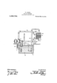
The accompanying. drawing illustrates diagrammatically a system embodying my invention.
The condenser 1 is a closed receptacle into which the steam to be condensed is admitted. It is traversed by tubes 2 through which cooling water is circulated by a pump 8. The waterof condensation passes off through the pipe 1. The uncondensabie gases are drawn ofl through a pipe 5 by the centrifugal air pump 6, which is of the water- 'throwing type and sucks up its water through a pipe 7 from a tank 8. The steam which happens to be drawn out of the c0ndenser at the same time with the uncondensable gases is condensed in the centrifugal ing water through the pipe 9 into the tank 8. By reason of this the water level rises in the tank and gradually lifts a float 10 attached to a valve 11 at the lower end of a pipe 12 which leads from the tank into the upper part of the condenser, where it is prefcra ly provided with a perforated distributer 13. When the valve opens, thevacuum in the condenser sucks u water from the tank until its level sin sto normal again, and the valve closes. The amount of water so drawn off thus corresponds very closely to the amount of steam condensed in the air-pump. This operation is repeated continuously at intervals, so that the loss of boiler water is automatically made up.
If it is deemed important to' keep the throwing water as cool as possible, the suc tion opening of the pipe 12 must be located just below the surface of the water in the tank 8, because the warm water of condensation coming from the centrifugal air If, on the other hand, it is desired to supply cool water to the condenser, the suction opening of the pipe 12 must be farther down: more as shown in the drawing.
It is desirable to keep the throwing water as cool as possible, and this may be accomplished by surrounding the intake pipe 7 with a jacket 1-1 through which flows the cooling water supplied to the condenser by the circulating pump 3. In passing through the air pump the temperature of the throwing water is raised about half a degree, but the withdrawal of the warm water from the upper part of the tank, together with the action of the water in the cooling jacket, results in maintaining an approximately constant temperature for the water supplied to the centrifugal pump.
In accordance with the provisions of the patent statutes, I have described the principle of operation of my invention, together with the apparatus which I now consider to represent the best embodiment thereof; but I desire to have it understood that the apparatus shown is only illustrative, and that the invention can be carried out by other means.
What I claim as new and desire to secure by Letters Patent of the United States, is,
1.. The combination with a surface condenser, of means for circulating cooling water through it, an outlet for condensation &
- pump connected with the steam space therein, said pump acting to raise the pressure of the air and gases received from the condenser to atmospheric pressure, a tank from which said pump draws water and to which the discharge therefrom returns, and means for automatically returning water from said tank to the steam space of said condenser.
3. The combination with a surface condenser, of a'centrifugal water-throwing airpump connected therewith, a tank from which said pump draws water and to which its overflow returns, and means for automatically returning to said condenser from said tank a quantity of water approximately equal to that resulting from the condensation of the steam drawn off by said pump.
4. The combination with a surface condenser, of a centrifugal water-throwing airpump connected therewith, a tank from which said pump draws water and to which its overflow returns, a pipe connecting the water in said tank with the condenser, a valve controlling said pipe, and means for automatically opening said valve when the level of the water rises above normal in said tank.
5. The combination with a surface cone denser, of a centrifugal water-throwing air pump connected therewith, a tank from macros reetly connected to said valve to open the same when the water level rises above normal,
6. The combination with a surface con denser, of a centrifugal water-throwing air pump connected therewith, a tank from which said pump draws its water and to which its overflow returns, a circulating pump connected with said condenser, and means whereby the cooling water supplied to said circulating pump is caused to cool the water supplied to said centrifugal airpump.
7. The combination with a surface con denser,-of a centrifugal water-throwing airpump connected therewith, a tank from which said pump draws water and to which its overflow returns, a jacket surrounding the intake pipe of said pump, and a circulating pump having its supply pipe connect ed with said jacket.
8. The combination with a surface con: denser, of means for circulating water through it to condense the steam, an outlet forthe condensation water, a centrifugal water-throwing air-pump connected with the steam space therein, said pump acting to condense a limited amount of steam and to raise the pressure of air and gas received from the condenser to atmospheric pressure, means permitting air and gas to separate from the discharge of said pump, and means for returning the water caused by the con:
densation of said limited amount of steam by the pump to the steam space of the con denser.
WALTER KIESER.
Witnesses:
OTTO GLowINs, FRIEDRICH SAss.
Copies of this patent may be obtained for five cents each, by addressing the Washington, D. G.
Priority Applications (1)
| Application Number | Priority Date | Filing Date | Title |
|---|---|---|---|
| US51677809A US1020702A (en) | 1909-09-08 | 1909-09-08 | Surface condenser. |
Applications Claiming Priority (1)
| Application Number | Priority Date | Filing Date | Title |
|---|---|---|---|
| US51677809A US1020702A (en) | 1909-09-08 | 1909-09-08 | Surface condenser. |
Publications (1)
| Publication Number | Publication Date |
|---|---|
| US1020702A true US1020702A (en) | 1912-03-19 |
Family
ID=3089000
Family Applications (1)
| Application Number | Title | Priority Date | Filing Date |
|---|---|---|---|
| US51677809A Expired - Lifetime US1020702A (en) | 1909-09-08 | 1909-09-08 | Surface condenser. |
Country Status (1)
| Country | Link |
|---|---|
| US (1) | US1020702A (en) |
-
1909
- 1909-09-08 US US51677809A patent/US1020702A/en not_active Expired - Lifetime
Similar Documents
| Publication | Publication Date | Title |
|---|---|---|
| US2217410A (en) | Heat exchange apparatus | |
| US2570247A (en) | Condenser | |
| US1986165A (en) | Distillation apparatus | |
| US1636361A (en) | Water heating and deaerating | |
| US2023630A (en) | Feed water degassing apparatus | |
| US874113A (en) | Vacuum heating system. | |
| US2168902A (en) | Surface condenser | |
| US1742998A (en) | Method and apparatus for treating liquids | |
| US1575157A (en) | Condenser installation | |
| US927591A (en) | System of heating by aid of vacuum. | |
| US951110A (en) | Apparatus for recovering alcohol from the lining of barrels, &c. | |
| US1966791A (en) | Method of and apparatus for handling heating system returns | |
| US1628471A (en) | Feed-water heater | |
| US1591822A (en) | Heater | |
| US1142785A (en) | Hot-water heating system. | |
| US1542544A (en) | Separation of air and dissolved gases from liquids | |
| US586968A (en) | Arthur graham glasgow | |
| US1145497A (en) | Water-still. | |
| US1130319A (en) | Apparatus relating to the withdrawal of air and water from steam-condensers. | |
| US679107A (en) | Hot-water tank. | |
| US1024547A (en) | Boyers | |
| US1971775A (en) | Vacuum condensation pump | |
| US785614A (en) | Steam-condenser. | |
| US1769746A (en) | Condensing apparatus | |
| US1153217A (en) | Condenser. |