US1020311A - Lathe-center. - Google Patents
Lathe-center. Download PDFInfo
- Publication number
- US1020311A US1020311A US44227508A US1908442275A US1020311A US 1020311 A US1020311 A US 1020311A US 44227508 A US44227508 A US 44227508A US 1908442275 A US1908442275 A US 1908442275A US 1020311 A US1020311 A US 1020311A
- Authority
- US
- United States
- Prior art keywords
- tip
- lathe
- center
- work
- shank
- Prior art date
- Legal status (The legal status is an assumption and is not a legal conclusion. Google has not performed a legal analysis and makes no representation as to the accuracy of the status listed.)
- Expired - Lifetime
Links
- 238000010276 construction Methods 0.000 description 3
- MXCPYJZDGPQDRA-UHFFFAOYSA-N dialuminum;2-acetyloxybenzoic acid;oxygen(2-) Chemical compound [O-2].[O-2].[O-2].[Al+3].[Al+3].CC(=O)OC1=CC=CC=C1C(O)=O MXCPYJZDGPQDRA-UHFFFAOYSA-N 0.000 description 2
- CWYNVVGOOAEACU-UHFFFAOYSA-N Fe2+ Chemical compound [Fe+2] CWYNVVGOOAEACU-UHFFFAOYSA-N 0.000 description 1
- 235000004443 Ricinus communis Nutrition 0.000 description 1
- 229910001315 Tool steel Inorganic materials 0.000 description 1
- 229910000754 Wrought iron Inorganic materials 0.000 description 1
- 230000001050 lubricating effect Effects 0.000 description 1
- 238000000034 method Methods 0.000 description 1
- 239000002245 particle Substances 0.000 description 1
- 238000007790 scraping Methods 0.000 description 1
Images
Classifications
-
- B—PERFORMING OPERATIONS; TRANSPORTING
- B23—MACHINE TOOLS; METAL-WORKING NOT OTHERWISE PROVIDED FOR
- B23B—TURNING; BORING
- B23B23/00—Tailstocks; Centres
- B23B23/04—Live centres
-
- Y—GENERAL TAGGING OF NEW TECHNOLOGICAL DEVELOPMENTS; GENERAL TAGGING OF CROSS-SECTIONAL TECHNOLOGIES SPANNING OVER SEVERAL SECTIONS OF THE IPC; TECHNICAL SUBJECTS COVERED BY FORMER USPC CROSS-REFERENCE ART COLLECTIONS [XRACs] AND DIGESTS
- Y10—TECHNICAL SUBJECTS COVERED BY FORMER USPC
- Y10T—TECHNICAL SUBJECTS COVERED BY FORMER US CLASSIFICATION
- Y10T82/00—Turning
- Y10T82/25—Lathe
- Y10T82/2568—Center
Definitions
- This invention relates to lathes and more particularly to a lathe center having a removable tip.
- the invention has for one of its objects to provide a comparatively simple, inexpensive and reliable lathe center adapted for live or dead heads of the lathe, provision being made on the centers intended for the dead head spindle for lubricating the work.
- Another object of the invention is to so design the center that the body or shank thereof can be used indefinitely while the tips can be renewed as occasion requires.
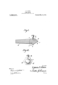
- Figure 1 is a central longitudinal section of the lathe :center intended for the dead head.
- Fig. 2 is an end view.
- A designates the shank or body of the center which is tapered in one direction so as to fit in the sleeve or spindle of the lathe head, and the larger end of the shank has a central bore 1 that is threaded for receiving the tip B.
- the tip shown in Fig. 1 is formed with a rearwardly-extending stud 2 that is threaded to screw into the socket 1, and the tip is provided with a shoulder 3 against which the shank bears when the tip is screwed home, and surrounding the tip is a flange 4 which is of larger diameter than the shank and provided peripherally with a gripping surface to receive a wrench for removing or applying the tip.
- the tip extends outwardly beyond the flange and Its workholding end is of conical shape or formed into a point 5 so as to fit in a center opening in the work.
- the tip has an L-shaped passage 6 that terminates in the surface of the cone at a suitable distance above the apex thereof, and the inner end of the passage turns upwardly at 7 and opens through said flange for receiving anoil cup 8 of any approved construction.
- Qil feeds from the cup downwardly into the passage and discharges from the latter on the cone at the top side thereof so as to run down toward the point and lubricate the work.
- the tips can be used interchangeably and when they become worn or injured, new ones can be substituted without necessitating ,the scraping of the body of the center.
- shank may be fitted to either the live or dead spindle of a lathe, and in either position the required work-holding tip may be fitted thereto best adapted for the particular work in hand.
- shank may he of castor wrought iron and the work-holding Up of tool steel tempered to the desired degree so as to resist wear.
- the work-holding tip comprises a body having essentially three parts, an intermedi;
Landscapes
- Engineering & Computer Science (AREA)
- Mechanical Engineering (AREA)
- Auxiliary Devices For Machine Tools (AREA)
Description
L. S. R'
LATHE. OB
APPLIUATION rum) JULY 7, 190a.
1,020,31 1. Patented Mar.12,1912.
2] n ucnfor. Lyman 5.12101. ym/ Means W 52m -9 61mm;
LYMAN S. RICH, OF BOSTON, MASSACHUSETTS.
LATHE-CENTER.
Specification of Letters Patent;
Patented Mar. 12, 1912.
Application filed July 7, 1908. Serial No. 442,275?
To all whom it may concern:
Be it'known that I, LYMAN S. RICH, a citizen of the United States, residing at Boston, in the county of Suffolk and State of Massachusetts, have invented new and useful Improvements in Lathe-Centers, of which the following is a specification.
This invention relates to lathes and more particularly to a lathe center having a removable tip.
The invention has for one of its objects to provide a comparatively simple, inexpensive and reliable lathe center adapted for live or dead heads of the lathe, provision being made on the centers intended for the dead head spindle for lubricating the work.
Another object of the invention is to so design the center that the body or shank thereof can be used indefinitely while the tips can be renewed as occasion requires.
With these objects in view and others, as will appear as the description proceeds, the invention comprises the various novel features of construction and arrangement of parts which will be more fully described hereinafter and set forth with particularity in the claim appended hereto.
In the accompanying drawing, which illustrates one embodiment of the invention, Figure 1 is a central longitudinal section of the lathe :center intended for the dead head. Fig. 2 is an end view.
Similar reference characters are employed to designate corresponding parts throughout both views.
,Referring to the drawing, A designates the shank or body of the center which is tapered in one direction so as to fit in the sleeve or spindle of the lathe head, and the larger end of the shank has a central bore 1 that is threaded for receiving the tip B. The tip shown in Fig. 1 is formed with a rearwardly-extending stud 2 that is threaded to screw into the socket 1, and the tip is provided with a shoulder 3 against which the shank bears when the tip is screwed home, and surrounding the tip is a flange 4 which is of larger diameter than the shank and provided peripherally with a gripping surface to receive a wrench for removing or applying the tip. The tip extends outwardly beyond the flange and Its workholding end is of conical shape or formed into a point 5 so as to fit in a center opening in the work. The tip has an L-shaped passage 6 that terminates in the surface of the cone at a suitable distance above the apex thereof, and the inner end of the passage turns upwardly at 7 and opens through said flange for receiving anoil cup 8 of any approved construction. Qil feeds from the cup downwardly into the passage and discharges from the latter on the cone at the top side thereof so as to run down toward the point and lubricate the work. The tips can be used interchangeably and when they become worn or injured, new ones can be substituted without necessitating ,the scraping of the body of the center.
From the foregoipg description, taken in connection with the accompanying drawing, the advantages of the construction and of the method of operation will be readily apparent to those skilled in the art to which the invention appertains, and while I have described'the principle of operation of the invention, together with the device which I now consider to be the best embodiment thereof, I desire to have it understood that the device slglown is merely illustrative, and that such 0 anges may be made when desired as are within the scope of the claim appended hereto.
It is further noted that the shank may be fitted to either the live or dead spindle of a lathe, and in either position the required work-holding tip may be fitted thereto best adapted for the particular work in hand.
It is further understood that the shank may he of castor wrought iron and the work-holding Up of tool steel tempered to the desired degree so as to resist wear. It
is not necessary to provide a shank for each work holding tip, hencethe initial cost of providing a number of different centers is materially reduced and the storage space for keeping the same when not in use is but little.
The work-holding tip comprises a body having essentially three parts, an intermedi;
ate annular gripping flange-at, a threaded ment of the work. It is further of advantage because the lateral portion of the oil duct or passage extends through the upper portion of the flange 4:; hence it is elevated and not liable to receive any particles which would tend to clog the opening, and moreover the stem of the oil cup is prevented from being injured by contact of the Work therewith. I consider it of especial advantage also to have the oil passage or duct 6 open directly above the apex of the cone 5 rather than through the point thereof or in any other position. If it opened through the apex of the duct 6 it would destroy the point of the tip, but opening where it does it permits the oil to flow onto the face of the cone and dawn over its apex and around its sides.
oeaen ing terminal screw'threads in one enchand a tip having a stem threaded in said screw threads and formed with a comcal ternnnal and an oil duct extending from a point.
medial of the extremity ofthe conical terminal and the side of the said tip and having its entrance extending through said side and provided with an oil cup communicating with said entrance.
In testimony whereof I affix my signature in presence of two witnesses.
LYMAN S. RICH.
Witnesses:
WV. It. CHIPoHAsE, ROBERT MEARS.
Priority Applications (1)
| Application Number | Priority Date | Filing Date | Title |
|---|---|---|---|
| US44227508A US1020311A (en) | 1908-07-07 | 1908-07-07 | Lathe-center. |
Applications Claiming Priority (1)
| Application Number | Priority Date | Filing Date | Title |
|---|---|---|---|
| US44227508A US1020311A (en) | 1908-07-07 | 1908-07-07 | Lathe-center. |
Publications (1)
| Publication Number | Publication Date |
|---|---|
| US1020311A true US1020311A (en) | 1912-03-12 |
Family
ID=3088609
Family Applications (1)
| Application Number | Title | Priority Date | Filing Date |
|---|---|---|---|
| US44227508A Expired - Lifetime US1020311A (en) | 1908-07-07 | 1908-07-07 | Lathe-center. |
Country Status (1)
| Country | Link |
|---|---|
| US (1) | US1020311A (en) |
-
1908
- 1908-07-07 US US44227508A patent/US1020311A/en not_active Expired - Lifetime
Similar Documents
| Publication | Publication Date | Title |
|---|---|---|
| US756339A (en) | Composite drill. | |
| GB511033A (en) | Improvements in and relating to screws and self-tapping screwdrivers | |
| US1229565A (en) | Countersink. | |
| US1404016A (en) | Drill bit and lubricator | |
| US1020311A (en) | Lathe-center. | |
| US430299A (en) | Centering-tool | |
| US1398679A (en) | Tool-holder | |
| US1034724A (en) | Tool-shank. | |
| US1346245A (en) | Chuck | |
| US379214A (en) | Capping axle-nuts | |
| US1928841A (en) | Method of and means fob attaching | |
| US728276A (en) | Drill-chuck. | |
| US2848798A (en) | Combination work piece aligner and clamping tool | |
| US1069437A (en) | Lubricator. | |
| US1004203A (en) | Cutter-head-securing device. | |
| US396663A (en) | morisseau | |
| US1256462A (en) | Boring-tool holder. | |
| US1038755A (en) | Chuck. | |
| US859976A (en) | Yielding chuck for taps and drills. | |
| US1343795A (en) | Chuck for holding drills, reamers, and the like | |
| US487847A (en) | Die-stock oiler | |
| US838638A (en) | Drill-chuck. | |
| US932045A (en) | Lubricator. | |
| US474265A (en) | Lathe-center | |
| US1044319A (en) | Axle-lubricator. |