US1020249A - Safety-fuse. - Google Patents
Safety-fuse. Download PDFInfo
- Publication number
- US1020249A US1020249A US63916611A US1911639166A US1020249A US 1020249 A US1020249 A US 1020249A US 63916611 A US63916611 A US 63916611A US 1911639166 A US1911639166 A US 1911639166A US 1020249 A US1020249 A US 1020249A
- Authority
- US
- United States
- Prior art keywords
- plug
- casing
- fuse
- fusible element
- caps
- Prior art date
- Legal status (The legal status is an assumption and is not a legal conclusion. Google has not performed a legal analysis and makes no representation as to the accuracy of the status listed.)
- Expired - Lifetime
Links
Images
Classifications
-
- H—ELECTRICITY
- H01—ELECTRIC ELEMENTS
- H01H—ELECTRIC SWITCHES; RELAYS; SELECTORS; EMERGENCY PROTECTIVE DEVICES
- H01H85/00—Protective devices in which the current flows through a part of fusible material and this current is interrupted by displacement of the fusible material when this current becomes excessive
- H01H85/02—Details
- H01H85/30—Means for indicating condition of fuse structurally associated with the fuse
- H01H85/303—Movable indicating elements
Definitions
- IRVIN E BARRICKLOW, F ANTIOCH, CALIFORNIA.
- the invention relates to a fuse, and more particularly to the class of safety fuses.
- the primary object of the invention is the provision of a fuse in which the fusible conductor, when melted or severed, will be separated at its severed end, so as to prevent the formation of an arc, thereby assuring a positive blow-out in the fuse for interrupting an electric circuit.
- Another object of the invention is the provision of a fuse in which the fusible element, when severed on an overload or short circuit, will be separated at its broken point, and one end of the fuse simultaneously projected to indicate that a eut out has occurred in the circuit, the fuse being provided with a casing, in which the ends thereof are readily removable for refilling thereof upon the melting of the fusible element, and also that will permit the replacement or introduction of a new fusible element within the casing.
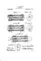
- Figure 1 is a vertical longitudinal sectional view of a fuse constructed in accordance with the invention.
- Fig. 2 is a similar view of a slight modification thereof.
- Fig. 3 is an end elevation of -the fuse shown in Fig. 1.
- Fig. 4 is an end elevation of the fuse shown in Fig. 2.
- Fig. 5 is a vert-ical longitudinal sectional view of a further modification of fuse.
- Fig. 6 is an end elevation thereof.
- the safety fuse comprises a cylindrical or tubular casing '5, preferably constructed of fiber or other suitable material, the same being open at its opposite ends, which ends are adapted to be closed by removable caps 6 and 7, respectively, the peripheral flanges S of which are adapted to telescope exteriorly upon the casing 5, and are 'fastened thereto by means of screw members 9, so that the caps may be removed, when desired.
- the cap 6 is formed with a central depression forming an inwardly extending sub- ⁇ stantially cup-shaped socket 10, while the cap 7 is formed with a central inwardly eX- tending boss 1l arranged in alinementwith a displaceable plug 12 passed through a ⁇ central aperture formed in the wall of the socket depression l10 of the cap 6, the outer end of the plug 12 being formed with a circular head 13 of a diameter corresponding to the socket 10, and slidably fits therein. l
- Entirely lillingfthe casing 5 is a refracl tory powder 14A, through the center-of which is passed a fusible element, such as asoft metal wire 15, preferablyformed from lead, y
- the fusible element or wire 15 being passed through alining passages 16 formed centrally in the plug 12 and boss 11, and has its ends secured to the cap 7 and the head 13 of the plug 12, respectively, by means of screw members 16.
- a coiled expansion spring 17 Surrounding the plug 12 is a coiled expansion spring 17, one end of which is fixed to the bottom wall ofr the socketdepression 10, and its opposite end fixed to the head 13 of the plug, so that upon the melting of the fusible element or wire 15 constituting the same, the said plug and its head 13 will be forced outwardly in the socket 10, thereby indicating a cut out in the-circuit, the cut out occurring upon the overloading or a dangerous heat being developed in the circuit.
- annular rim lor abutment shoulder 18 Formed on the inner end of the plug is an annular rim lor abutment shoulder 18 which prevents the plug from separating from the cap 6 when moving outwardly in the socket 10 therein, and in this manner the outward movementof the plug is limit-ed.
- the spring 17 will act upon the head 13 of the plug 12, thereby forcing it outwardly, thus separating the broken ends'of the said fusible element andv closing the ends of the casing 5 are provided with seats 21 which extend from the-socket 22 anti plug 23 into the peripheral flanges 24 of thesaid caps, and are adapted to receive the ends of the fusible element 25, which ends thereof are connect-ed with the screw members 26 connecting the said caps 19 and 20 to the easing at one side thereof, with.
- the caps being substantially identical to those shown in Figs. 1 and 3of the drawings.
- the screw members 24 connecting the caps 19 and 2O to the casing 5 are also threaded in brackets 27 mounted interiorly of the said casing 5 to more securely hold the said screw members engaged in the casing 5 of the fuse.
- the plug 22 in its head 28 is also formed with a channel seat 29, in which lies one end of the fusible element 23, the seat 29 being in alinement with the seat 21 'in the cap 19.
- the ends of the fusible element 23 will normally lie flush with the outer faces of the caps, and not project or protrude beyond the same.
- FIGs. 5 and 6 there is shown a still further modification of fuse, wherein the open ends of the casing 5 have telescoped therein flat blade supporting contact terminal brackets 30, in which are held the usual fiat blade contact terminals 31 which project outwardly through suitable elon gated slots formed in removable caps 32 and 33, respectively, which are fitted on and close the open ends of the said casing 5, the cap 33 being formed with an inwardly directed central boss 34, while the cap 32 is formed with an inwardly directed central socketed extension 35, alining with the boss 34, and in the socketed extension is arranged a slidable plug 36 which is provided with a central passage 37, and likewise a central passage 38 is provided in the boss 34, the said passages being in alinement with each other, and through the same is passed the fusible element, such as a soft metal wire 39.
- the fusible element such as a soft metal wire 39.
- a coiled expansion spring 42 Interposed between the slidable plug 36 and the inner end of the socketed extension is a coiled expansion spring 42, thelatter surrounding the fusible element and is adapted, on the melting thereof, to move the plug outwardly in the socketed extension
- the casing 5 is filled with refractory 'powder 45, as usual.
- the casing 5 may be readily and easily refilled by removing the caps at the ends of the same, after the fusible element has been melted. Also, a new fusible element may be replaced in a ready and convenient manner, as will be obvious. lt will be noted that when the fusible element is severed, or melted, the movable plug will indicate such to be the case, thereby giving notice of a cut-out in the circuit.
- a safety fuse comprising a tubular casing having open ends, removable caps detachably connected with the easing and closing said open ends, a refractory powder entirely filling the said casing, an inwardly extending boss formed centrally on one of the caps, an inwardly extending socketed member formed centrallyon the other cap, a slidable plug fitted in the socketed member, a fusible element passed through the plug and vthe boss and secured at ropposite ends exteriorly on the casing, and expansible means acting upon theplug to project the same on the melting of the fusible element.
- a safety fuse comprising a casing naving'removable caps at opposite ends, a refractory filling within' the casing, 'a socket extension directed inwardly from one of the caps within the refractory filling, a slidable plug fitted within the socket extension,o a. fusible element passed. through the plug, refractory filling and the other cap, means securing the ends of the fusible element exteriorly of the casing, and a coiled expansion spring confined within the socket eze tension and adapted to act upon the said plug to move the same outwardly of its socket on the breaking of the fusible elel1 ment.
Landscapes
- Fuses (AREA)
Description
I. E. BARRICKLOW.
SAFETY FUSE.
APPLICATION FILED JULY 18,1911
1,020,249. Patented Mar.12,1912,
IRVIN E. BARRICKLOW, F ANTIOCH, CALIFORNIA.
SAFETY-IE'USE..
' Specification of Letters Patent.
Patented Mar. 12, 1912.
Application led .Tuly 18, 1911. Serial 170.639,16@
10 alt whom 'it may concern:
Be 1t known that I, InviN E. BARnioKLow, a. citizen of the United States, residing at Antioch, in the county of Contra Costa and ,State of California, have invented new and useful Improvements in Safety-Fuses, of
which the following is a specification.
The invention relates to a fuse, and more particularly to the class of safety fuses.
The primary object of the invention is the provision of a fuse in which the fusible conductor, when melted or severed, will be separated at its severed end, so as to prevent the formation of an arc, thereby assuring a positive blow-out in the fuse for interrupting an electric circuit.
Another object of the invention is the provision of a fuse in which the fusible element, when severed on an overload or short circuit, will be separated at its broken point, and one end of the fuse simultaneously projected to indicate that a eut out has occurred in the circuit, the fuse being provided with a casing, in which the ends thereof are readily removable for refilling thereof upon the melting of the fusible element, and also that will permit the replacement or introduction of a new fusible element within the casing.
In the drawings,accompanying and forming a part of this specification, are illustrated the preferred forms of embodiment A,of the invention, which, to enable those skilled in the art to carry the invention into practice, will be set forth at length in the following description, while the novelty of the same will bc pointed out in the claims hereunto appended.
In the drawings: Figure 1 is a vertical longitudinal sectional view of a fuse constructed in accordance with the invention. Fig. 2 is a similar view of a slight modification thereof. Fig. 3 is an end elevation of -the fuse shown in Fig. 1. Fig. 4 is an end elevation of the fuse shown in Fig. 2. Fig. 5 is a vert-ical longitudinal sectional view of a further modification of fuse. Fig. 6 is an end elevation thereof. l
Similar reference characters indicate corresponding parts throughout the several views of the drawings.
Referring to Figs. 1 and 3 of the drawings, the safety fuse comprises a cylindrical or tubular casing '5, preferably constructed of fiber or other suitable material, the same being open at its opposite ends, which ends are adapted to be closed by removable caps 6 and 7, respectively, the peripheral flanges S of which are adapted to telescope exteriorly upon the casing 5, and are 'fastened thereto by means of screw members 9, so that the caps may be removed, when desired. The cap 6 is formed with a central depression forming an inwardly extending sub-` stantially cup-shaped socket 10, While the cap 7 is formed with a central inwardly eX- tending boss 1l arranged in alinementwith a displaceable plug 12 passed through a` central aperture formed in the wall of the socket depression l10 of the cap 6, the outer end of the plug 12 being formed with a circular head 13 of a diameter corresponding to the socket 10, and slidably fits therein. l
Entirely lillingfthe casing 5 isa refracl tory powder 14A, through the center-of which is passed a fusible element, such as asoft metal wire 15, preferablyformed from lead, y
although it may bemade from `any other fusible alloys, having a low degree of te nacity, the fusible element or wire 15 being passed through alining passages 16 formed centrally in the plug 12 and boss 11, and has its ends secured to the cap 7 and the head 13 of the plug 12, respectively, by means of screw members 16. y
Surrounding the plug 12 is a coiled expansion spring 17, one end of which is fixed to the bottom wall ofr the socketdepression 10, and its opposite end fixed to the head 13 of the plug, so that upon the melting of the fusible element or wire 15 constituting the same, the said plug and its head 13 will be forced outwardly in the socket 10, thereby indicating a cut out in the-circuit, the cut out occurring upon the overloading or a dangerous heat being developed in the circuit.
Formed on the inner end of the plug is an annular rim lor abutment shoulder 18 which prevents the plug from separating from the cap 6 when moving outwardly in the socket 10 therein, and in this manner the outward movementof the plug is limit-ed. When the metal l5 forming the fusible element becomes melted, the spring 17 will act upon the head 13 of the plug 12, thereby forcing it outwardly, thus separating the broken ends'of the said fusible element andv closing the ends of the casing 5 are provided with seats 21 which extend from the-socket 22 anti plug 23 into the peripheral flanges 24 of thesaid caps, and are adapted to receive the ends of the fusible element 25, which ends thereof are connect-ed with the screw members 26 connecting the said caps 19 and 20 to the easing at one side thereof, with. this exception, the caps `being substantially identical to those shown in Figs. 1 and 3of the drawings. The screw members 24 connecting the caps 19 and 2O to the casing 5 are also threaded in brackets 27 mounted interiorly of the said casing 5 to more securely hold the said screw members engaged in the casing 5 of the fuse. The plug 22 in its head 28 is also formed with a channel seat 29, in which lies one end of the fusible element 23, the seat 29 being in alinement with the seat 21 'in the cap 19. Thus it will be seen that the ends of the fusible element 23 will normally lie flush with the outer faces of the caps, and not project or protrude beyond the same.
. In Figs. 5 and 6, there is shown a still further modification of fuse, wherein the open ends of the casing 5 have telescoped therein flat blade supporting contact terminal brackets 30, in which are held the usual fiat blade contact terminals 31 which project outwardly through suitable elon gated slots formed in removable caps 32 and 33, respectively, which are fitted on and close the open ends of the said casing 5, the cap 33 being formed with an inwardly directed central boss 34, while the cap 32 is formed with an inwardly directed central socketed extension 35, alining with the boss 34, and in the socketed extension is arranged a slidable plug 36 which is provided with a central passage 37, and likewise a central passage 38 is provided in the boss 34, the said passages being in alinement with each other, and through the same is passed the fusible element, such as a soft metal wire 39. the ends of which are passed eXteriorly of the caps 32 and 33, and are fastened to one side of the casing 5 by means of screw members 40, which latter are passed through the caps, casing, and also engage in the brackets 30, and serve to hold the said parts in proper position., together with further screw members 41 which are passed through the caps, casing and said brackets, as will be clearly obvious.
Interposed between the slidable plug 36 and the inner end of the socketed extension is a coiled expansion spring 42, thelatter surrounding the fusible element and is adapted, on the melting thereof, to move the plug outwardly in the socketed extension Copies of this patent may be obtained. for ve cents each, by addressing the omefissoaer et Keet-eats, Wash'ingtom. t3.
35, thereby indicating that a eut-out has loccurred in the circuit, and also to separate the adjacent broken ends of the fusible ele ment to preventthe arcing of the circuit,- t
melting of the fusible element, theA outer end of the channel 43 forming an abutment shoulder 44 for the plug 36 to limit its out- Ward movement on the melting of the fusible element. The casing 5 is filled with refractory 'powder 45, as usual.
The casing 5 may be readily and easily refilled by removing the caps at the ends of the same, after the fusible element has been melted. Also, a new fusible element may be replaced in a ready and convenient manner, as will be obvious. lt will be noted that when the fusible element is severed, or melted, the movable plug will indicate such to be the case, thereby giving notice of a cut-out in the circuit.
What is claimed is:
1. A safety fuse, comprising a tubular casing having open ends, removable caps detachably connected with the easing and closing said open ends, a refractory powder entirely filling the said casing, an inwardly extending boss formed centrally on one of the caps, an inwardly extending socketed member formed centrallyon the other cap, a slidable plug fitted in the socketed member, a fusible element passed through the plug and vthe boss and secured at ropposite ends exteriorly on the casing, and expansible means acting upon theplug to project the same on the melting of the fusible element.
2. A safety fuse, comprising a casing naving'removable caps at opposite ends, a refractory filling within' the casing, 'a socket extension directed inwardly from one of the caps within the refractory filling, a slidable plug fitted within the socket extension,o a. fusible element passed. through the plug, refractory filling and the other cap, means securing the ends of the fusible element exteriorly of the casing, and a coiled expansion spring confined within the socket eze tension and adapted to act upon the said plug to move the same outwardly of its socket on the breaking of the fusible elel1 ment.
1n testimony whereof l aliix my signature 1n presence of two witnesses.
lRVlN E. BARRIClfliOll/ 1llfitnesses:
Banca Brown, d. 1. lnsr.
Priority Applications (1)
| Application Number | Priority Date | Filing Date | Title |
|---|---|---|---|
| US63916611A US1020249A (en) | 1911-07-18 | 1911-07-18 | Safety-fuse. |
Applications Claiming Priority (1)
| Application Number | Priority Date | Filing Date | Title |
|---|---|---|---|
| US63916611A US1020249A (en) | 1911-07-18 | 1911-07-18 | Safety-fuse. |
Publications (1)
| Publication Number | Publication Date |
|---|---|
| US1020249A true US1020249A (en) | 1912-03-12 |
Family
ID=3088547
Family Applications (1)
| Application Number | Title | Priority Date | Filing Date |
|---|---|---|---|
| US63916611A Expired - Lifetime US1020249A (en) | 1911-07-18 | 1911-07-18 | Safety-fuse. |
Country Status (1)
| Country | Link |
|---|---|
| US (1) | US1020249A (en) |
-
1911
- 1911-07-18 US US63916611A patent/US1020249A/en not_active Expired - Lifetime
Similar Documents
| Publication | Publication Date | Title |
|---|---|---|
| US4276531A (en) | Nonresetable thermally actuated switch | |
| US3183327A (en) | Indicating fuse | |
| US1020249A (en) | Safety-fuse. | |
| US2296627A (en) | Time lag fuse | |
| US1438609A (en) | Fuse | |
| US2294767A (en) | Electric protective device | |
| US1353123A (en) | Cartridge-fuse | |
| US2180975A (en) | Time lag fuse | |
| US1121876A (en) | Rechargeable electric fuse. | |
| US1262683A (en) | Electric fuse. | |
| US1413997A (en) | Method of and means for breaking electric arcs | |
| US897852A (en) | Safety-fuse. | |
| US2234480A (en) | Safety indicator fuse | |
| US2218274A (en) | Circuit interrupter | |
| US1841686A (en) | Refillable cartridge fuse | |
| US538090A (en) | Electric cut-out | |
| US1388269A (en) | Inclosed or cartridge fuse | |
| US1677298A (en) | Thermal plug cut-out | |
| US1308518A (en) | Fuse-plug | |
| US590750A (en) | caetweight | |
| US1685958A (en) | Thermal cut-out | |
| US561159A (en) | Island | |
| US1213777A (en) | Inclosed-fuse element. | |
| US1074806A (en) | Inclosed electric fuse. | |
| US1475558A (en) | Fuse plug |