US10200293B2 - Dynamically offloading flows from a service chain - Google Patents

Dynamically offloading flows from a service chain Download PDF

Info

Publication number
US10200293B2
US10200293B2 US14/884,523 US201514884523A US10200293B2 US 10200293 B2 US10200293 B2 US 10200293B2 US 201514884523 A US201514884523 A US 201514884523A US 10200293 B2 US10200293 B2 US 10200293B2
Authority
US
United States
Prior art keywords
service function
function instance
service
traffic flow
packets
Prior art date
Legal status (The legal status is an assumption and is not a legal conclusion. Google has not performed a legal analysis and makes no representation as to the accuracy of the status listed.)
Active, expires
Application number
US14/884,523
Other versions
US20160112337A1 (en
Inventor
Hong Zhang
Louis FOURIE
Current Assignee (The listed assignees may be inaccurate. Google has not performed a legal analysis and makes no representation or warranty as to the accuracy of the list.)
Huawei Cloud Computing Technologies Co Ltd
Original Assignee
FutureWei Technologies Inc
Priority date (The priority date is an assumption and is not a legal conclusion. Google has not performed a legal analysis and makes no representation as to the accuracy of the date listed.)
Filing date
Publication date
Application filed by FutureWei Technologies Inc filed Critical FutureWei Technologies Inc
Priority to US14/884,523 priority Critical patent/US10200293B2/en
Assigned to FUTUREWEI TECHNOLOGIES, INC. reassignment FUTUREWEI TECHNOLOGIES, INC. ASSIGNMENT OF ASSIGNORS INTEREST (SEE DOCUMENT FOR DETAILS). Assignors: ZHANG, HONG, FOURIE, LOUIS
Publication of US20160112337A1 publication Critical patent/US20160112337A1/en
Application granted granted Critical
Publication of US10200293B2 publication Critical patent/US10200293B2/en
Assigned to Huawei Cloud Computing Technologies Co., Ltd. reassignment Huawei Cloud Computing Technologies Co., Ltd. ASSIGNMENT OF ASSIGNORS INTEREST (SEE DOCUMENT FOR DETAILS). Assignors: FUTUREWEI TECHNOLOGIES, INC.
Active legal-status Critical Current
Adjusted expiration legal-status Critical

Links

Images

Classifications

    • HELECTRICITY
    • H04ELECTRIC COMMUNICATION TECHNIQUE
    • H04LTRANSMISSION OF DIGITAL INFORMATION, e.g. TELEGRAPHIC COMMUNICATION
    • H04L47/00Traffic control in data switching networks
    • H04L47/10Flow control; Congestion control
    • H04L47/35Flow control; Congestion control by embedding flow control information in regular packets, e.g. piggybacking
    • HELECTRICITY
    • H04ELECTRIC COMMUNICATION TECHNIQUE
    • H04LTRANSMISSION OF DIGITAL INFORMATION, e.g. TELEGRAPHIC COMMUNICATION
    • H04L47/00Traffic control in data switching networks
    • H04L47/10Flow control; Congestion control
    • H04L47/17Interaction among intermediate nodes, e.g. hop by hop
    • HELECTRICITY
    • H04ELECTRIC COMMUNICATION TECHNIQUE
    • H04LTRANSMISSION OF DIGITAL INFORMATION, e.g. TELEGRAPHIC COMMUNICATION
    • H04L69/00Network arrangements, protocols or services independent of the application payload and not provided for in the other groups of this subclass
    • H04L69/22Parsing or analysis of headers

Definitions

  • the present invention relates to telecommunications, and, in particular embodiments, to techniques for dynamically offloading packet flows from a service function within a service chain.
  • a service chain is composed of a sequence of service function instances that reside on various service nodes.
  • the packets are processed by the various service function instances, with each service function instance applying a service function (e.g., firewall, network access translation (NAT), deep packet inspection (DPI), etc.) prior to forwarding the packet to the next service node.
  • a service function instance may only need to access the first few packets of a traffic flow to perform the function, or to determine whether the function needs to be performed on the flow.
  • a service function instance receiving a particular type of traffic flow may complete the service function using the initial packets and without processing/receiving subsequent packets of the flow.
  • a service function instance performing firewall processing may determine that a flow is benign based on the initial packets.
  • a service function instance performing DPI processing may only need to inspect the first few packets of a traffic flow to extract the identification information.
  • a service function instance performing content delivery network (CDN) caching may learn early on that content in a traffic flow does not satisfy a caching criterion, at which point there is no processing (e.g., caching) to be performed on the remaining packets.
  • CDN content delivery network
  • a method for dynamically offloading flows from a service chain includes receiving a first portion of a traffic flow over the service chain path from a service function instance.
  • the service function instance is positioned between an upstream service function instance and a downstream service function instance on the service chain path.
  • the method further comprises determining that a by-pass criterion is satisfied after processing at least some of the first portion of the traffic flow, embedding a by-pass indication in a service chain header (SCH) of at least one packet in the first portion of the traffic flow, and forwarding the at least one packet to a data plane entity.
  • the by-pass indication prompts the data plane entity to re-route a remaining portion of the traffic flow directly from the upstream service function instance to a next-hop service function instance.
  • An apparatus for performing this method is also provided.
  • another method for dynamically offloading flows from a service chains includes receiving a by-pass indication message from a reporting service function instance while a traffic flow is being forwarded over a first service chain path.
  • the reporting service function instance is positioned between an upstream service function instance and a next-hop service function instance on the first service chain path.
  • the by-pass indication message is received after a first portion of the traffic flow has been processed by the reporting service function instance.
  • the method further comprises sending a re-routing request message to the upstream service function instance.
  • the re-routing request message prompts the upstream service function instance to by-pass the reporting service function instance by forwarding a remaining portion of the traffic flow directly to the next-hop service function instance.
  • An apparatus for performing this method is also provided.
  • FIG. 1 illustrates a diagram of an embodiment service chain
  • FIG. 2 illustrates a diagram of an embodiment service chain architecture adapted to dynamically by-pass service function instances using out-of-band control plane signaling
  • FIG. 3 illustrates a diagram of an embodiment service chain architecture adapted to dynamically by-pass service function instances using in-band data plane signaling
  • FIG. 4 illustrates a diagram of an embodiment service chain header
  • FIG. 5 illustrates a diagram of an embodiment by-pass flow descriptor type length value (TLV) structure
  • FIG. 6 illustrates a diagram of an embodiment sampling flow descriptor type length value (TLV) structure
  • FIG. 7 illustrates a diagram of an embodiment computing platform.
  • aspects of this disclosure provide techniques for dynamically re-routing a remaining portion of a traffic flow (e.g., the trailing packets) to by-pass a service function instance after the service function instance has processed a first portion of the traffic flow.
  • Dynamic by-passing of a service function instance can be achieved through a control plane mechanism.
  • a service function instance When using the control plane mechanism, a service function instance will communicate a by-pass indication to a control plane entity (e.g., a service orchestrator) after processing a first portion of a traffic flow when a by-pass criterion is satisfied.
  • a control plane entity e.g., a service orchestrator
  • control plane entity will re-route the traffic flow from the initial path (which includes the service function instance) to an alternate path (e.g., a detour) that by-passes the service function instance.
  • This path re-routing may be achieved by communicating a re-routing instruction to an upstream node or entity, such as flow classifier or service function forwarder.
  • the re-routing instruction may prompt the upstream node/entity to forward a remaining portion of the traffic flow (e.g., the trailing packets) on the alternate service chain path, thereby by-passing the service function instance.
  • the by-pass indication and re-routing instructions may be communicated through control plane signaling.
  • Dynamic by-passing of a service function instance can also be achieved through a data plane mechanism.
  • a service function instance When using the data plane mechanism, a service function instance will include a by-pass indication (e.g., a by-pass bit a by-pass flow descriptor type length value (TLV) field, etc.) in a service chain header (SCH) appended to one or more packets in an initial portion of the traffic flow when a by-pass criterion is satisfied.
  • a by-pass indication e.g., a by-pass bit a by-pass flow descriptor type length value (TLV) field, etc.
  • a data plane forwarding entity e.g., the service function forwarder
  • the by-pass indication will prompt the data plane forwarding entity to re-route a remaining portion of the traffic flow directly from the upstream service function instance to a next-hop service function instance (e.g., the service function instance following the by-passed service function instance), thereby diverting the remaining packets around the by-passed service function instance.
  • the by-passed service function instance may want to periodically sample a packet (or a group of packets) in the re-routed traffic flow. This can be accomplished by including a sampling indication (e.g., a sample flow descriptor TLV field, etc.) in the service chain header (SCH).
  • FIG. 1 illustrates an embodiment service chain 100 .
  • the service chain 100 comprises a classifier 105 , service function instances (e.g., service functions (SFs)) 110 , service function forwarders (SFFs) 115 , and a service transport overlay 125 .
  • a data plane service function chain (SFC) 130 begins at an ingress classifier 105 and extends through various SFs 110 and the SFFs 115 , and then may terminate at the SFF 116 .
  • the data plane SFC 130 includes an interface D 1 135 extending between the service transport overlay 125 and the classifier 105 and an interface D 2 140 extending between the SF 110 and the SFF 115 .
  • the classifier 105 may be configured to classify a traffic flow.
  • the classifier 105 may determine that an incoming traffic flow is associated with the data plane SFC 130 .
  • the SFFs 115 , 116 may be components of a service function forwarding plane that are responsible for forwarding packets in a traffic flow to the next-hop service function on the data plane SFC 130 .
  • the SFs 110 may be data plane entities on the data plane SFC 130 that perform service functions on traffic flows forwarded over the data plane SFC 130 .
  • FIG. 2 illustrates an embodiment service chain architecture 200 adapted to dynamically by-pass a first service function instance (SI 1 ) 211 using out-of-band control plane signaling.
  • the service chain architecture 200 comprises a flow classifier 205 , service function instances 211 , 212 , a service function forwarder 215 , a service orchestrator 220 , a first service chain 225 , and a second service chain 226 .
  • the SI 1 211 When the SI 1 211 has determined that it no longer needs to access any further packets for a traffic flow being transported over the first service chain 225 , it sends a by-pass notification over a control channel to a service orchestrator 220 in order to request re-routing of a remaining portion of the traffic flow.
  • the service orchestrator 220 receives the by-pass notification from the first SI 1 211 , the service orchestrator 220 sends a control plane request to the upstream flow classifier 205 to re-route the first service chain 225 to the second service chain 226 , thereby by-passing the SI 1 211 .
  • the second service chain 226 may be established prior to the service orchestrator 220 receiving the by-pass indication from the SI 1 211 . In other embodiments, the service orchestrator 220 dynamically establishes the second service chain 226 upon receiving the by-pass indication from the first SI 1 211 .
  • aspects of this disclosure also provide a data plane mechanism for dynamically by-passing service function instances on a service chain path. More specifically, a service function instance places a by-pass indication in a service chain header of one or more packets in a first portion of traffic flow to re-route a remaining portion of the traffic flow directly from an up-stream service function instance to the next-hop service function instance.
  • Service chain headers are described in Internet Engineering Task Force (IETF) publication entitled “Service Chain Header draft-zhang-sfc-sch-01,” which is incorporated herein by reference as if reproduced in its entirety.
  • the service chain architecture 300 comprises a flow steering entity 305 , a service function forwarder 315 , service function instances 311 , 312 , a first service chain 325 , and a second service chain 326 .
  • the SI 1 311 includes a by-pass indication in the SCH of a packet in the traffic flow when a by-pass criterion is satisfied.
  • the by-pass indication may be a dedicated by-pass bit/flag or a by-pass flow descriptor TLV.
  • Placing the by-pass indication in the SCH of a packet in the first service chain 325 prompts the flow steering entity 305 to re-route a remaining portion of the traffic flow to the next-hop service function instance. This may be achieved by re-routing the traffic flow from the first service chain 325 to the second service chain 326 .
  • the data plane by-pass notification mechanism may provide faster re-routing (e.g., lower latency) than the control plane by-pass notification mechanism.
  • a by-pass indication may be signaled using a dedicated by-pass indication bit/flag in a service chain header.
  • FIG. 4 illustrates an embodiment service chain header (SCH) 400 comprising a by-pass bit flag.
  • the service by-pass bit 405 e.g., the B bit
  • the service by-pass bit 405 may be set (or cleared) to signal a by-pass indication.
  • a service function instance may set (or clear) the service by-pass bit 405 in the SCH 400 of a data packet prior to sending the packet to the service function forwarder.
  • the service function forwarder may re-route a remaining portion of the specified traffic flow around the service function instance.
  • the service function forwarder may clear (or set) the service by-pass bit 405 in the SCH before forwarding the packet to the next downstream SFF.
  • the SCH 400 may include a metadata TLV field 410 .
  • the metadata TLV field 410 may be a variable length field that carries one or more TLVs, e.g., a by-pass flow descriptor TLV, a traffic flow descriptor TLV, a sample flow descriptor TLV, etc.
  • a by-pass indication may also be signaled by including a by-pass flow descriptor TLV in the SCH 400 .
  • FIG. 5 illustrates an embodiment by-pass flow descriptor TLV 500 adapted to signal a by-pass indication.
  • the by-pass flow descriptor TLV 500 comprises a TLV type field 505 , a TLV length field 510 , a metadata value field 515 , a group of reserved bits (Rs) 525 , a source internet protocol (IP) address 530 , a destination IP address 535 , a protocol 540 , a source transmission control protocol/user datagram protocol (TCP/UDP) port 545 , and a destination TCP/UDP port 550 .
  • IP internet protocol
  • TCP/UDP source transmission control protocol/user datagram protocol
  • a service function instance may add the by-pass flow descriptor TLV 500 to the metadata TLV field 410 of the SCH 400 in order to signal a by-pass notification to a service function forwarder.
  • the TLV type field 505 and the metadata value field 515 in the by-pass flow descriptor TLV 500 may be set to a certain bits pattern to indicate remaining packets in a traffic flow are to be sent directly to the next-hop service function instance.
  • the source/destination IP addresses 530 , 535 , the protocol 540 , and the source/destination TCP/UDP ports 545 , 550 are used to identify the traffic flow to be by-passed.
  • the service function forwarder may remove the by-pass flow descriptor TLV 500 from the SCH before forwarding the packet to the next downstream SFF as it only has significance between the reporting service function and its service function forwarder.
  • a by-passed service function instance may want to periodically sample a packet (or a group of packets) in the re-routed traffic flow. This can be accomplished by including a sampling indication (e.g., a sample flow descriptor TLV field, etc.) in the SCH 400 .
  • FIG. 6 illustrates an embodiment sampling flow descriptor TLV 600 comprising a TLV type field 605 , a TLV length field 610 , a sample interval value field 615 , and a group of reserved bits (Rs) 625 .
  • a service instances may add the sampling flow descriptor TLV 600 to the SCH 400 in order to request that the service function forwarder send one or more of the flow packets to the by-passed service function instance at some points in the future so that the by-passed service function instance may sample the packet(s).
  • the sampling flow descriptor TLV 600 may also be included in the SCH 400 of sampled packet(s) to request that the service function forwarder resume forwarding of the traffic flow to the previously by-passed service function instance.
  • the TLV type field 605 and the sample interval field 615 in the sampling flow descriptor TLV 600 may be set to a certain bit pattern to signal a sample or resume operation.
  • the sample interval value 615 may specify the number of packets to be skipped, or as a time interval between sampled packets.
  • the service function forwarder may remove the sample flow descriptor TLV 600 from the SCH before forwarding the packet to the next downstream SFF.
  • the sampling flow descriptor TLV 600 may accompany a by-pass indication in the SCH 400 of a packet to indicate that the service function instance wants to sample an occasional packet in remaining portions of the traffic flow, which will largely by-pass the service function instance by virtue of the by-pass indication.
  • the sampling flow descriptor TLV 600 may be included in the SCH 400 of sampled packet(s) to indicate that the service function instance wants to resume receiving the flow.
  • aspects of this disclosure allow for service off-loading from service nodes. This allows service nodes to offer a greater service capacity as only the first few packets of a flow need to be sent to the service function instance running a service node. This allows fewer service nodes to be deployed in the network, resulting in cost savings and reduced CAPEX. Aspects of this disclosure improve latency of the packet flow as remaining portions of a traffic flow are expeditiously forwarded to the next hop service function instance, thereby reducing transit times. This also results in improved quality of service, as the packet latency for packet flows is reduced. Aspects of this disclosure reduce network traffic since subsequent packets for the flow do not need to be steered through the network to that service node.
  • FIG. 7 is a block diagram of a processing system that may be used for implementing the devices and methods disclosed herein. Specific devices may utilize all of the components shown, or only a subset of the components, and levels of integration may vary from device to device. Furthermore, a device may contain multiple instances of a component, such as multiple processing units, processors, memories, transmitters, receivers, etc.
  • the processing system may comprise a processing unit equipped with one or more input/output devices, such as a speaker, microphone, mouse, touchscreen, keypad, keyboard, printer, display, and the like.
  • the processing unit may include a central processing unit (CPU), memory, a mass storage device, a video adapter, and an I/O interface connected to a bus.
  • CPU central processing unit
  • the bus may be one or more of any type of several bus architectures including a memory bus or memory controller, a peripheral bus, video bus, or the like.
  • the CPU may comprise any type of electronic data processor.
  • the memory may comprise any type of system memory such as static random access memory (SRAM), dynamic random access memory (DRAM), synchronous DRAM (SDRAM), read-only memory (ROM), a combination thereof, or the like.
  • SRAM static random access memory
  • DRAM dynamic random access memory
  • SDRAM synchronous DRAM
  • ROM read-only memory
  • the memory may include ROM for use at boot-up, and DRAM for program and data storage for use while executing programs.
  • the mass storage device may comprise any type of storage device configured to store data, programs, and other information and to make the data, programs, and other information accessible via the bus.
  • the mass storage device may comprise, for example, one or more of a solid state drive, hard disk drive, a magnetic disk drive, an optical disk drive, or the like.
  • the video adapter and the I/O interface provide interfaces to couple external input and output devices to the processing unit.
  • input and output devices include the display coupled to the video adapter and the mouse/keyboard/printer coupled to the I/O interface.
  • Other devices may be coupled to the processing unit, and additional or fewer interface cards may be utilized.
  • a serial interface such as Universal Serial Bus (USB) (not shown) may be used to provide an interface for a printer.
  • USB Universal Serial Bus
  • the processing unit also includes one or more network interfaces, which may comprise wired links, such as an Ethernet cable or the like, and/or wireless links to access nodes or different networks.
  • the network interface allows the processing unit to communicate with remote units via the networks.
  • the network interface may provide wireless communication via one or more transmitters/transmit antennas and one or more receivers/receive antennas.
  • the processing unit is coupled to a local-area network or a wide-area network for data processing and communications with remote devices, such as other processing units, the Internet, remote storage facilities, or the like.

Abstract

Dynamically by-passing a service function instance on a service chain after the service function instance has processed the first few packets of a traffic flow may improve the overall processing efficiency of the service chain. When using a control plane mechanism, a service function instance communicates a by-pass indication to a control plane entity to prompt the control plane entity to re-route remaining portions of the traffic flow around the service function instance. When using a data plane mechanism, a service function instance includes a by-pass indication in a service chain header (SCH) of a packet in a traffic flow, and forwards the packet to a data plane entity. The by-pass indication will prompt the data plane entity to re-route remaining portions of the traffic flow around the service function instance.

Description

This patent application claims priority to U.S. Provisional Application No. 62/066,061, filed on Oct. 20, 2014 and entitled “Dynamically Offloading Flows from a Service Chain,” which is hereby incorporated by reference herein as if reproduced in its entirety.
TECHNICAL FIELD
The present invention relates to telecommunications, and, in particular embodiments, to techniques for dynamically offloading packet flows from a service function within a service chain.
BACKGROUND
A service chain is composed of a sequence of service function instances that reside on various service nodes. When a traffic flow is forwarded over a service chain, the packets are processed by the various service function instances, with each service function instance applying a service function (e.g., firewall, network access translation (NAT), deep packet inspection (DPI), etc.) prior to forwarding the packet to the next service node. In some implementations, a service function instance may only need to access the first few packets of a traffic flow to perform the function, or to determine whether the function needs to be performed on the flow. For instance, a service function instance receiving a particular type of traffic flow (e.g., a long-lived flow) may complete the service function using the initial packets and without processing/receiving subsequent packets of the flow. As one example, a service function instance performing firewall processing may determine that a flow is benign based on the initial packets. As another example, a service function instance performing DPI processing may only need to inspect the first few packets of a traffic flow to extract the identification information. As yet another example, a service function instance performing content delivery network (CDN) caching may learn early on that content in a traffic flow does not satisfy a caching criterion, at which point there is no processing (e.g., caching) to be performed on the remaining packets.
SUMMARY
Technical advantages are generally achieved, by embodiments of this disclosure which describe techniques for dynamically offloading flows from a service chain.
In accordance with an embodiment, a method for dynamically offloading flows from a service chain is provided. In this example, the method includes receiving a first portion of a traffic flow over the service chain path from a service function instance. The service function instance is positioned between an upstream service function instance and a downstream service function instance on the service chain path. The method further comprises determining that a by-pass criterion is satisfied after processing at least some of the first portion of the traffic flow, embedding a by-pass indication in a service chain header (SCH) of at least one packet in the first portion of the traffic flow, and forwarding the at least one packet to a data plane entity. The by-pass indication prompts the data plane entity to re-route a remaining portion of the traffic flow directly from the upstream service function instance to a next-hop service function instance. An apparatus for performing this method is also provided.
In accordance with another embodiment, another method for dynamically offloading flows from a service chains is provided. In this example, the method includes receiving a by-pass indication message from a reporting service function instance while a traffic flow is being forwarded over a first service chain path. The reporting service function instance is positioned between an upstream service function instance and a next-hop service function instance on the first service chain path. The by-pass indication message is received after a first portion of the traffic flow has been processed by the reporting service function instance. The method further comprises sending a re-routing request message to the upstream service function instance. The re-routing request message prompts the upstream service function instance to by-pass the reporting service function instance by forwarding a remaining portion of the traffic flow directly to the next-hop service function instance. An apparatus for performing this method is also provided.
BRIEF DESCRIPTION OF THE DRAWINGS
For a more complete understanding of the present invention, and the advantages thereof, reference is now made to the following descriptions taken in conjunction with the accompanying drawing, in which:
FIG. 1 illustrates a diagram of an embodiment service chain;
FIG. 2 illustrates a diagram of an embodiment service chain architecture adapted to dynamically by-pass service function instances using out-of-band control plane signaling;
FIG. 3 illustrates a diagram of an embodiment service chain architecture adapted to dynamically by-pass service function instances using in-band data plane signaling;
FIG. 4 illustrates a diagram of an embodiment service chain header;
FIG. 5 illustrates a diagram of an embodiment by-pass flow descriptor type length value (TLV) structure;
FIG. 6 illustrates a diagram of an embodiment sampling flow descriptor type length value (TLV) structure; and
FIG. 7 illustrates a diagram of an embodiment computing platform.
Corresponding numerals and symbols in the different figures generally refer to corresponding parts unless otherwise indicated. The figures are drawn to clearly illustrate the relevant aspects of the embodiments and are not necessarily drawn to scale.
DETAILED DESCRIPTION OF ILLUSTRATIVE EMBODIMENTS
The making and using of embodiments of this disclosure are discussed in detail below. It should be appreciated, however, that the present invention provides many applicable inventive concepts that can be embodied in a wide variety of specific contexts. The specific embodiments discussed herein are merely illustrative of specific ways to make and use the invention, and do not limit the scope of the invention.
In conventional service chain architectures, all packets of a traffic flow are forwarded to each service function instance on the service chain. As a result, service function instances requiring only the first few initial packets may nevertheless receive the entire traffic flow. Accordingly, techniques for dynamically by-passing service function instances after the first few packets are needed in order to reduce processing latencies and increase the overall processing efficiencies of service chain networks.
Aspects of this disclosure provide techniques for dynamically re-routing a remaining portion of a traffic flow (e.g., the trailing packets) to by-pass a service function instance after the service function instance has processed a first portion of the traffic flow. Dynamic by-passing of a service function instance can be achieved through a control plane mechanism. When using the control plane mechanism, a service function instance will communicate a by-pass indication to a control plane entity (e.g., a service orchestrator) after processing a first portion of a traffic flow when a by-pass criterion is satisfied. In response, the control plane entity will re-route the traffic flow from the initial path (which includes the service function instance) to an alternate path (e.g., a detour) that by-passes the service function instance. This path re-routing may be achieved by communicating a re-routing instruction to an upstream node or entity, such as flow classifier or service function forwarder. The re-routing instruction may prompt the upstream node/entity to forward a remaining portion of the traffic flow (e.g., the trailing packets) on the alternate service chain path, thereby by-passing the service function instance. The by-pass indication and re-routing instructions may be communicated through control plane signaling.
Dynamic by-passing of a service function instance can also be achieved through a data plane mechanism. When using the data plane mechanism, a service function instance will include a by-pass indication (e.g., a by-pass bit a by-pass flow descriptor type length value (TLV) field, etc.) in a service chain header (SCH) appended to one or more packets in an initial portion of the traffic flow when a by-pass criterion is satisfied. Those packet(s) will then be forwarded to a data plane forwarding entity (e.g., the service function forwarder), where the by-pass indication will prompt the data plane forwarding entity to re-route a remaining portion of the traffic flow directly from the upstream service function instance to a next-hop service function instance (e.g., the service function instance following the by-passed service function instance), thereby diverting the remaining packets around the by-passed service function instance. In some embodiments, the by-passed service function instance may want to periodically sample a packet (or a group of packets) in the re-routed traffic flow. This can be accomplished by including a sampling indication (e.g., a sample flow descriptor TLV field, etc.) in the service chain header (SCH). These and other aspects are discussed in greater detail below.
FIG. 1 illustrates an embodiment service chain 100. As shown, the service chain 100 comprises a classifier 105, service function instances (e.g., service functions (SFs)) 110, service function forwarders (SFFs) 115, and a service transport overlay 125. A data plane service function chain (SFC) 130 begins at an ingress classifier 105 and extends through various SFs 110 and the SFFs 115, and then may terminate at the SFF 116. As shown, the data plane SFC 130 includes an interface D1 135 extending between the service transport overlay 125 and the classifier 105 and an interface D2 140 extending between the SF 110 and the SFF 115. The classifier 105 may be configured to classify a traffic flow. For example, the classifier 105 may determine that an incoming traffic flow is associated with the data plane SFC 130. The SFFs 115, 116 may be components of a service function forwarding plane that are responsible for forwarding packets in a traffic flow to the next-hop service function on the data plane SFC 130. The SFs 110 may be data plane entities on the data plane SFC 130 that perform service functions on traffic flows forwarded over the data plane SFC 130.
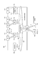
Aspects of this disclosure provide a control plane mechanism for dynamically by-passing service function instances on a service chain path. FIG. 2 illustrates an embodiment service chain architecture 200 adapted to dynamically by-pass a first service function instance (SI1) 211 using out-of-band control plane signaling. As shown, the service chain architecture 200 comprises a flow classifier 205, service function instances 211, 212, a service function forwarder 215, a service orchestrator 220, a first service chain 225, and a second service chain 226.
When the SI1 211 has determined that it no longer needs to access any further packets for a traffic flow being transported over the first service chain 225, it sends a by-pass notification over a control channel to a service orchestrator 220 in order to request re-routing of a remaining portion of the traffic flow. When the service orchestrator 220 receives the by-pass notification from the first SI1 211, the service orchestrator 220 sends a control plane request to the upstream flow classifier 205 to re-route the first service chain 225 to the second service chain 226, thereby by-passing the SI1 211. In some embodiments, the second service chain 226 may be established prior to the service orchestrator 220 receiving the by-pass indication from the SI1 211. In other embodiments, the service orchestrator 220 dynamically establishes the second service chain 226 upon receiving the by-pass indication from the first SI1 211.
Aspects of this disclosure also provide a data plane mechanism for dynamically by-passing service function instances on a service chain path. More specifically, a service function instance places a by-pass indication in a service chain header of one or more packets in a first portion of traffic flow to re-route a remaining portion of the traffic flow directly from an up-stream service function instance to the next-hop service function instance. Service chain headers (SCHs) are described in Internet Engineering Task Force (IETF) publication entitled “Service Chain Header draft-zhang-sfc-sch-01,” which is incorporated herein by reference as if reproduced in its entirety. FIG. 3 illustrates an embodiment service chain architecture 300 adapted to dynamically by-pass a first service function instance (SI1) 311 using in-band data plane signaling. As shown, the service chain architecture 300 comprises a flow steering entity 305, a service function forwarder 315, service function instances 311, 312, a first service chain 325, and a second service chain 326. The SI1 311 includes a by-pass indication in the SCH of a packet in the traffic flow when a by-pass criterion is satisfied. The by-pass indication may be a dedicated by-pass bit/flag or a by-pass flow descriptor TLV. Placing the by-pass indication in the SCH of a packet in the first service chain 325 prompts the flow steering entity 305 to re-route a remaining portion of the traffic flow to the next-hop service function instance. This may be achieved by re-routing the traffic flow from the first service chain 325 to the second service chain 326. The data plane by-pass notification mechanism may provide faster re-routing (e.g., lower latency) than the control plane by-pass notification mechanism.
A by-pass indication may be signaled using a dedicated by-pass indication bit/flag in a service chain header. FIG. 4 illustrates an embodiment service chain header (SCH) 400 comprising a by-pass bit flag. The service by-pass bit 405 (e.g., the B bit) may be set (or cleared) to signal a by-pass indication. For example, a service function instance may set (or clear) the service by-pass bit 405 in the SCH 400 of a data packet prior to sending the packet to the service function forwarder. Upon receiving the packet carrying the service by-pass bit 405, the service function forwarder may re-route a remaining portion of the specified traffic flow around the service function instance. The service function forwarder may clear (or set) the service by-pass bit 405 in the SCH before forwarding the packet to the next downstream SFF. In addition to the by-pass indication bit 405, the SCH 400 may include a metadata TLV field 410. The metadata TLV field 410 may be a variable length field that carries one or more TLVs, e.g., a by-pass flow descriptor TLV, a traffic flow descriptor TLV, a sample flow descriptor TLV, etc.
A by-pass indication may also be signaled by including a by-pass flow descriptor TLV in the SCH 400. FIG. 5 illustrates an embodiment by-pass flow descriptor TLV 500 adapted to signal a by-pass indication. As shown, the by-pass flow descriptor TLV 500 comprises a TLV type field 505, a TLV length field 510, a metadata value field 515, a group of reserved bits (Rs) 525, a source internet protocol (IP) address 530, a destination IP address 535, a protocol 540, a source transmission control protocol/user datagram protocol (TCP/UDP) port 545, and a destination TCP/UDP port 550. A service function instance may add the by-pass flow descriptor TLV 500 to the metadata TLV field 410 of the SCH 400 in order to signal a by-pass notification to a service function forwarder. The TLV type field 505 and the metadata value field 515 in the by-pass flow descriptor TLV 500 may be set to a certain bits pattern to indicate remaining packets in a traffic flow are to be sent directly to the next-hop service function instance. The source/destination IP addresses 530, 535, the protocol 540, and the source/destination TCP/ UDP ports 545, 550 are used to identify the traffic flow to be by-passed. The service function forwarder may remove the by-pass flow descriptor TLV 500 from the SCH before forwarding the packet to the next downstream SFF as it only has significance between the reporting service function and its service function forwarder.
In some embodiments, a by-passed service function instance may want to periodically sample a packet (or a group of packets) in the re-routed traffic flow. This can be accomplished by including a sampling indication (e.g., a sample flow descriptor TLV field, etc.) in the SCH 400. FIG. 6 illustrates an embodiment sampling flow descriptor TLV 600 comprising a TLV type field 605, a TLV length field 610, a sample interval value field 615, and a group of reserved bits (Rs) 625. A service instances may add the sampling flow descriptor TLV 600 to the SCH 400 in order to request that the service function forwarder send one or more of the flow packets to the by-passed service function instance at some points in the future so that the by-passed service function instance may sample the packet(s). The sampling flow descriptor TLV 600 may also be included in the SCH 400 of sampled packet(s) to request that the service function forwarder resume forwarding of the traffic flow to the previously by-passed service function instance. The TLV type field 605 and the sample interval field 615 in the sampling flow descriptor TLV 600 may be set to a certain bit pattern to signal a sample or resume operation. The sample interval value 615 may specify the number of packets to be skipped, or as a time interval between sampled packets. The service function forwarder may remove the sample flow descriptor TLV 600 from the SCH before forwarding the packet to the next downstream SFF.
As an example, the sampling flow descriptor TLV 600 may accompany a by-pass indication in the SCH 400 of a packet to indicate that the service function instance wants to sample an occasional packet in remaining portions of the traffic flow, which will largely by-pass the service function instance by virtue of the by-pass indication. In another example, the sampling flow descriptor TLV 600 may be included in the SCH 400 of sampled packet(s) to indicate that the service function instance wants to resume receiving the flow.
Aspects of this disclosure allow for service off-loading from service nodes. This allows service nodes to offer a greater service capacity as only the first few packets of a flow need to be sent to the service function instance running a service node. This allows fewer service nodes to be deployed in the network, resulting in cost savings and reduced CAPEX. Aspects of this disclosure improve latency of the packet flow as remaining portions of a traffic flow are expeditiously forwarded to the next hop service function instance, thereby reducing transit times. This also results in improved quality of service, as the packet latency for packet flows is reduced. Aspects of this disclosure reduce network traffic since subsequent packets for the flow do not need to be steered through the network to that service node.
FIG. 7 is a block diagram of a processing system that may be used for implementing the devices and methods disclosed herein. Specific devices may utilize all of the components shown, or only a subset of the components, and levels of integration may vary from device to device. Furthermore, a device may contain multiple instances of a component, such as multiple processing units, processors, memories, transmitters, receivers, etc. The processing system may comprise a processing unit equipped with one or more input/output devices, such as a speaker, microphone, mouse, touchscreen, keypad, keyboard, printer, display, and the like. The processing unit may include a central processing unit (CPU), memory, a mass storage device, a video adapter, and an I/O interface connected to a bus.
The bus may be one or more of any type of several bus architectures including a memory bus or memory controller, a peripheral bus, video bus, or the like. The CPU may comprise any type of electronic data processor. The memory may comprise any type of system memory such as static random access memory (SRAM), dynamic random access memory (DRAM), synchronous DRAM (SDRAM), read-only memory (ROM), a combination thereof, or the like. In an embodiment, the memory may include ROM for use at boot-up, and DRAM for program and data storage for use while executing programs.
The mass storage device may comprise any type of storage device configured to store data, programs, and other information and to make the data, programs, and other information accessible via the bus. The mass storage device may comprise, for example, one or more of a solid state drive, hard disk drive, a magnetic disk drive, an optical disk drive, or the like.
The video adapter and the I/O interface provide interfaces to couple external input and output devices to the processing unit. As illustrated, examples of input and output devices include the display coupled to the video adapter and the mouse/keyboard/printer coupled to the I/O interface. Other devices may be coupled to the processing unit, and additional or fewer interface cards may be utilized. For example, a serial interface such as Universal Serial Bus (USB) (not shown) may be used to provide an interface for a printer.
The processing unit also includes one or more network interfaces, which may comprise wired links, such as an Ethernet cable or the like, and/or wireless links to access nodes or different networks. The network interface allows the processing unit to communicate with remote units via the networks. For example, the network interface may provide wireless communication via one or more transmitters/transmit antennas and one or more receivers/receive antennas. In an embodiment, the processing unit is coupled to a local-area network or a wide-area network for data processing and communications with remote devices, such as other processing units, the Internet, remote storage facilities, or the like.
While this invention has been described with reference to illustrative embodiments, this description is not intended to be construed in a limiting sense. Various modifications and combinations of the illustrative embodiments, as well as other embodiments of the invention, will be apparent to persons skilled in the art upon reference to the description. It is therefore intended that the appended claims encompass any such modifications or embodiments.

Claims (20)

What is claimed is:
1. A method for dynamically by-passing service function instances using data plane signaling, the method comprising:
receiving, by a service function instance, a packet of an initial portion of a traffic flow over a service chain path and processing the packet at the service function instance, the packet preceding one or more remaining packets in the traffic flow, wherein the service function instance is positioned between an upstream service function instance and a downstream service function instance on a service chain path;
determining, by the service function instance, that a by-pass criterion is satisfied after processing the packet at the service function instance, and based thereon embedding, by the service function instance, a by-pass indication in a service chain header of the packet; and
forwarding the packet to a data plane entity, the by-pass indication embedded in the service chain header of the packet of the traffic flow instructing the data plane entity to re-route the one or more remaining packets of the traffic flow directly from the upstream service function instance to a next-hop service function instance such that the one or more remaining packets of the traffic flow bypass the service function instance.
2. The method of claim 1, wherein the by-pass indication comprises a dedicated field in the service chain header.
3. The method of claim 2, wherein embedding the by-pass indication in the service chain header of the packet comprises:
setting or clearing the by-pass indication in the service chain header to signal the by-pass indication.
4. The method of claim 1, wherein the by-pass indication comprises a by-pass flow descriptor type length value (TLV).
5. The method of claim 4, wherein embedding the by-pass indication in the service chain header of the packet comprises:
placing the by-pass flow descriptor TLV in a metadata TLVs of the service chain header.
6. The method of claim 1, further comprising:
embedding, by the service function instance, a sampling indication in the service chain header of the packet, wherein the sampling indication prompts the data plane entity to occasionally forward one or more sampled packets of the traffic flow to the service function instance such that the service function instance can sample the one or more sampled packets, the packet preceding the one or more sampled packets, the one or more sampled packets being different than the one or more remaining packets.
7. The method of claim 6, wherein the sampling indication comprises a sample flow descriptor TLV.
8. The method of claim 7, wherein embedding the sampling indication in the service chain header comprises:
placing the sample flow descriptor TLV in metadata TLVs of the service chain header.
9. The method of claim 6, further comprising:
receiving, by the service function instance, the one or more sampled packets, the one or more sampled packets being communicated to the service function instance in accordance with the sampling indication;
determining that a resume criterion has been satisfied after at least partially processing the one or more sampled packets;
embedding, by the service function instance, a resume indication in a service chain header of the one or more sampled packets; and
sending the one or more sampled packets to the data plane entity, wherein the resume indication prompts the data plane entity to resume forwarding residual packets of the traffic flow to the service function instance, the residual packets being preceded by the one or more sampled packets in the traffic flow.
10. The method of claim 9, wherein embedding the resume indication in the service chain header of the sampled packet comprises:
embedding a resume flow descriptor TLV in metadata TLVs of the service chain header of the one or more sampled packets.
11. An apparatus adapted to host a service function instance of a service chain, the apparatus comprising:
a processor; and
a computer readable storage medium storing programming for execution by the processor, the programming including instructions to:
receive a packet of an initial portion of a traffic flow over a service chain path and processing the packet at the service function instance, the packet preceding one or more remaining packets in the traffic flow, wherein the service function instance is positioned between an upstream service function instance and a downstream service function instance on the service chain path;
determine that a by-pass criterion is satisfied after processing the packet at the service function instance, and based thereon embed a by-pass indication in a service chain header of the packet; and
forward the packet to a data plane entity, the by-pass indication embedded in the service chain header of the packet of the traffic flow instructing the data plane entity to re-route the one or more remaining packets of the traffic flow directly from the upstream service function instance to a next-hop service function instance such that the one or more remaining packets of the traffic flow bypass the service function instance.
12. The apparatus of claim 11, wherein the by-pass indication comprises a dedicated field in the service chain header.
13. The apparatus of claim 11, wherein the by-pass indication comprises a by-pass flow descriptor type length value (TLV).
14. The apparatus of claim 11, wherein the programming further includes instructions to:
embed a sampling indication in the service chain header of the packet, wherein the sampling indication prompts the data plane entity to occasionally forward one or more sampled packets in the remaining portion of the traffic flow to the service function to enable the service function instance to sample the one or more sampled packets, the packet preceding the one or more sampled packets, the one or more sampled packets being different than the one or more remaining packets.
15. The apparatus of claim 14, wherein the programming further includes instructions to:
receive the one or more sampled packets from the remaining portion of the traffic flow, the one or more sampled packets being communicated to the service function instance in accordance with the sampling indication;
determine that a resume criterion has been satisfied after at least partially processing the one or more sampled packets;
embed a resume indication in a service chain header of the one or more sampled packets; and
send the one or more sampled packet to the data plane entity, wherein the resume indication prompts the data plane entity to resume forwarding residual packets of the traffic flow to the service function instance, the residual packets being preceded by the one or more sampled packets in the traffic flow.
16. A method for dynamically by-passing service function instances using control plane signaling, the method comprising:
receiving, by a control plane entity, a by-pass indication message from a reporting service function instance while a traffic flow is being forwarded over a first service chain path, wherein the reporting service function instance is positioned between an upstream service function instance and a next-hop service function instance on the first service chain path, and wherein the by-pass indication message is received after a packet of the traffic flow has been processed by the reporting service function instance, the packet preceding one or more remaining packets in the traffic flow; and
sending, by the control plane entity, a re-routing request message to the upstream service function instance, wherein the re-routing request message prompts the upstream service function instance to forward the one or more remaining packets of the traffic flow directly to the next-hop service function instance such that the one or more remaining packets of the traffic flow bypass the reporting service function instance.
17. The method of claim 16, wherein the one or more remaining packets are forwarded over a second service chain path extending directly from the upstream service function instance to the next-hop service function instance, the second service chain path excluding the reporting service function instance.
18. The method of claim 17, wherein the second service chain path was established prior to the control plane entity receiving the by-pass indication.
19. The method of claim 17, further comprising:
dynamically establishing the second service chain path after receiving the by-pass indication.
20. An apparatus adapted to host a control plane entity, the apparatus comprising:
a processor; and
a computer readable storage medium storing programming for execution by the processor, the programming including instructions to:
receive a by-pass indication message from a reporting service function instance while a traffic flow is being forwarded over a first service chain path, wherein the reporting service function instance is positioned between an upstream service function instance and a next-hop service function instance on the first service chain path, and wherein the by-pass indication message is received after a packet of the traffic flow has been processed by the reporting service function instance, the packet preceding one or more remaining packets in the traffic flow; and
send a re-routing request message to the upstream service function instance, wherein the re-routing request message prompts the upstream service function instance to forward the one or more remaining packets of the traffic flow directly to the next-hop service function instance such that the one or more remaining packets of the traffic flow bypass the reporting service function instance.
US14/884,523 2014-10-20 2015-10-15 Dynamically offloading flows from a service chain Active 2037-05-26 US10200293B2 (en)

Priority Applications (1)

Application Number Priority Date Filing Date Title
US14/884,523 US10200293B2 (en) 2014-10-20 2015-10-15 Dynamically offloading flows from a service chain

Applications Claiming Priority (2)

Application Number Priority Date Filing Date Title
US201462066061P 2014-10-20 2014-10-20
US14/884,523 US10200293B2 (en) 2014-10-20 2015-10-15 Dynamically offloading flows from a service chain

Publications (2)

Publication Number Publication Date
US20160112337A1 US20160112337A1 (en) 2016-04-21
US10200293B2 true US10200293B2 (en) 2019-02-05

Family

ID=55749966

Family Applications (1)

Application Number Title Priority Date Filing Date
US14/884,523 Active 2037-05-26 US10200293B2 (en) 2014-10-20 2015-10-15 Dynamically offloading flows from a service chain

Country Status (1)

Country Link
US (1) US10200293B2 (en)

Families Citing this family (7)

* Cited by examiner, † Cited by third party
Publication number Priority date Publication date Assignee Title
US11456959B2 (en) * 2015-02-26 2022-09-27 Telefonaktiebolaget Lm Ericsson (Publ) Sampling node and a method performed thereby for handling flows through a SDN between client(s) and origin server(s) of a communication network
US11356359B2 (en) * 2015-09-02 2022-06-07 Telefonaktiebolaget Lm Ericsson (Publ) Methods and network nodes for scalable top-of-chain selection in mobile service chaining
US10355983B2 (en) * 2016-05-09 2019-07-16 Cisco Technology, Inc. Traceroute to return aggregated statistics in service chains
US10333855B2 (en) * 2017-04-19 2019-06-25 Cisco Technology, Inc. Latency reduction in service function paths
US10749710B2 (en) * 2018-11-02 2020-08-18 Cisco Technology, Inc. Service offload or bypass initiated by a service function forwarder in a service function chaining network
US11411843B2 (en) * 2019-08-14 2022-08-09 Verizon Patent And Licensing Inc. Method and system for packet inspection in virtual network service chains
CN114338501B (en) * 2021-12-23 2023-08-11 中国电信股份有限公司 Method and device for adjusting network topology of service chain network, medium and controller

Citations (4)

* Cited by examiner, † Cited by third party
Publication number Priority date Publication date Assignee Title
US20080008194A1 (en) * 2006-07-07 2008-01-10 General Instrument Corporation Device, system and method for bypassing application specific data traffic past network routing devices
US7860100B2 (en) 2008-10-01 2010-12-28 Cisco Technology, Inc. Service path selection in a service network
US20140029418A1 (en) * 2012-07-27 2014-01-30 Pradeep G. Jain System and method for switching traffic from sub-optimal primary p2mp to standby p2mp
US20160099864A1 (en) * 2014-10-07 2016-04-07 Cisco Technology, Inc. Selective service bypass in service function chaining

Patent Citations (4)

* Cited by examiner, † Cited by third party
Publication number Priority date Publication date Assignee Title
US20080008194A1 (en) * 2006-07-07 2008-01-10 General Instrument Corporation Device, system and method for bypassing application specific data traffic past network routing devices
US7860100B2 (en) 2008-10-01 2010-12-28 Cisco Technology, Inc. Service path selection in a service network
US20140029418A1 (en) * 2012-07-27 2014-01-30 Pradeep G. Jain System and method for switching traffic from sub-optimal primary p2mp to standby p2mp
US20160099864A1 (en) * 2014-10-07 2016-04-07 Cisco Technology, Inc. Selective service bypass in service function chaining

Non-Patent Citations (2)

* Cited by examiner, † Cited by third party
Title
Inside Secure, "Technical Considerations for Mobile Data Offload with ePDG," White Paper, 9 pages. Available Nov. 24, 2015, http://www.insidesecure.com/Products-Technologies/Protocol-Security-Toolkits/QuickSec-R-Mobile-VPN-Client/Whitepapers/Technical-Considerations-for-Mobile-Data-Offload-with-ePDG.
Zhang, H., et al., "Service Chain Header," Network Working Group Internet Draft, May 9, 2014, 15 pages.

Also Published As

Publication number Publication date
US20160112337A1 (en) 2016-04-21

Similar Documents

Publication Publication Date Title
US10200293B2 (en) Dynamically offloading flows from a service chain
US9825856B2 (en) Service function chaining in a packet network
EP2944056B1 (en) Distributed traffic inspection in a telecommunications network
US9560017B2 (en) Methods and apparatus to route traffic in a virtual private network
CN110022264B (en) Method for controlling network congestion, access device and computer readable storage medium
US9847934B2 (en) Reducing packet reordering in flow-based networks
US8059650B2 (en) Hardware based parallel processing cores with multiple threads and multiple pipeline stages
US10375193B2 (en) Source IP address transparency systems and methods
US9531847B2 (en) Skipping and parsing internet protocol version 6 (IPv6) extension headers to reach upper layer headers
US10505846B2 (en) Resilient segment routing service hunting with TCP session stickiness
US11405319B2 (en) Tool port throttling at a network visibility node
US11595441B2 (en) Systems and methods for securing network paths
US20160344611A1 (en) Method and control node for handling data packets
US20190312770A1 (en) Border routers in multicast networks and methods of operating the same
CN103281257A (en) Method and device for processing protocol message
CN110545230B (en) Method and device for forwarding VXLAN message
US9548921B2 (en) Compression of routing information exchanges
US20120076147A1 (en) Method and System for Realizing Transmission of Message Between an Extended Processor and a Switch Chip
JP4040045B2 (en) Data transfer device
WO2016136813A1 (en) Communication device, terminal device, central server device, information processing system, telegram processing method and telegram generation method
US10171368B1 (en) Methods and apparatus for implementing multiple loopback links
US9350648B2 (en) System and method for loop suppression in transit networks
US20160134523A1 (en) Network routing system and network packet routing method thereof
US20150180775A1 (en) Communication System, Control Apparatus, Communication Method, and Program
US20230327994A1 (en) Systems and Methods for Handling Asymmetric SDWAN Traffic Flows

Legal Events

Date Code Title Description
AS Assignment

Owner name: FUTUREWEI TECHNOLOGIES, INC., TEXAS

Free format text: ASSIGNMENT OF ASSIGNORS INTEREST;ASSIGNORS:ZHANG, HONG;FOURIE, LOUIS;SIGNING DATES FROM 20141120 TO 20150506;REEL/FRAME:036980/0936

STCF Information on status: patent grant

Free format text: PATENTED CASE

AS Assignment

Owner name: HUAWEI CLOUD COMPUTING TECHNOLOGIES CO., LTD., CHINA

Free format text: ASSIGNMENT OF ASSIGNORS INTEREST;ASSIGNOR:FUTUREWEI TECHNOLOGIES, INC.;REEL/FRAME:059682/0738

Effective date: 20220228

MAFP Maintenance fee payment

Free format text: PAYMENT OF MAINTENANCE FEE, 4TH YEAR, LARGE ENTITY (ORIGINAL EVENT CODE: M1551); ENTITY STATUS OF PATENT OWNER: LARGE ENTITY

Year of fee payment: 4