US10199879B2 - Techniques for facilitating beacon sampling efficiencies in wireless power delivery environments - Google Patents
Techniques for facilitating beacon sampling efficiencies in wireless power delivery environments Download PDFInfo
- Publication number
- US10199879B2 US10199879B2 US15/196,769 US201615196769A US10199879B2 US 10199879 B2 US10199879 B2 US 10199879B2 US 201615196769 A US201615196769 A US 201615196769A US 10199879 B2 US10199879 B2 US 10199879B2
- Authority
- US
- United States
- Prior art keywords
- wireless power
- power receiver
- beacon signal
- receiver client
- directionality
- Prior art date
- Legal status (The legal status is an assumption and is not a legal conclusion. Google has not performed a legal analysis and makes no representation as to the accuracy of the status listed.)
- Active, expires
Links
Images


Classifications
-
- H—ELECTRICITY
- H02—GENERATION; CONVERSION OR DISTRIBUTION OF ELECTRIC POWER
- H02J—CIRCUIT ARRANGEMENTS OR SYSTEMS FOR SUPPLYING OR DISTRIBUTING ELECTRIC POWER; SYSTEMS FOR STORING ELECTRIC ENERGY
- H02J50/00—Circuit arrangements or systems for wireless supply or distribution of electric power
- H02J50/20—Circuit arrangements or systems for wireless supply or distribution of electric power using microwaves or radio frequency waves
- H02J50/23—Circuit arrangements or systems for wireless supply or distribution of electric power using microwaves or radio frequency waves characterised by the type of transmitting antennas, e.g. directional array antennas or Yagi antennas
-
- G—PHYSICS
- G01—MEASURING; TESTING
- G01S—RADIO DIRECTION-FINDING; RADIO NAVIGATION; DETERMINING DISTANCE OR VELOCITY BY USE OF RADIO WAVES; LOCATING OR PRESENCE-DETECTING BY USE OF THE REFLECTION OR RERADIATION OF RADIO WAVES; ANALOGOUS ARRANGEMENTS USING OTHER WAVES
- G01S1/00—Beacons or beacon systems transmitting signals having a characteristic or characteristics capable of being detected by non-directional receivers and defining directions, positions, or position lines fixed relatively to the beacon transmitters; Receivers co-operating therewith
- G01S1/02—Beacons or beacon systems transmitting signals having a characteristic or characteristics capable of being detected by non-directional receivers and defining directions, positions, or position lines fixed relatively to the beacon transmitters; Receivers co-operating therewith using radio waves
-
- H—ELECTRICITY
- H02—GENERATION; CONVERSION OR DISTRIBUTION OF ELECTRIC POWER
- H02J—CIRCUIT ARRANGEMENTS OR SYSTEMS FOR SUPPLYING OR DISTRIBUTING ELECTRIC POWER; SYSTEMS FOR STORING ELECTRIC ENERGY
- H02J50/00—Circuit arrangements or systems for wireless supply or distribution of electric power
- H02J50/20—Circuit arrangements or systems for wireless supply or distribution of electric power using microwaves or radio frequency waves
-
- H—ELECTRICITY
- H02—GENERATION; CONVERSION OR DISTRIBUTION OF ELECTRIC POWER
- H02J—CIRCUIT ARRANGEMENTS OR SYSTEMS FOR SUPPLYING OR DISTRIBUTING ELECTRIC POWER; SYSTEMS FOR STORING ELECTRIC ENERGY
- H02J50/00—Circuit arrangements or systems for wireless supply or distribution of electric power
- H02J50/40—Circuit arrangements or systems for wireless supply or distribution of electric power using two or more transmitting or receiving devices
-
- H—ELECTRICITY
- H02—GENERATION; CONVERSION OR DISTRIBUTION OF ELECTRIC POWER
- H02J—CIRCUIT ARRANGEMENTS OR SYSTEMS FOR SUPPLYING OR DISTRIBUTING ELECTRIC POWER; SYSTEMS FOR STORING ELECTRIC ENERGY
- H02J50/00—Circuit arrangements or systems for wireless supply or distribution of electric power
- H02J50/80—Circuit arrangements or systems for wireless supply or distribution of electric power involving the exchange of data, concerning supply or distribution of electric power, between transmitting devices and receiving devices
-
- H02J7/025—
-
- H02J7/42—
-
- H—ELECTRICITY
- H04—ELECTRIC COMMUNICATION TECHNIQUE
- H04W—WIRELESS COMMUNICATION NETWORKS
- H04W4/00—Services specially adapted for wireless communication networks; Facilities therefor
- H04W4/02—Services making use of location information
- H04W4/025—Services making use of location information using location based information parameters
-
- G—PHYSICS
- G01—MEASURING; TESTING
- G01S—RADIO DIRECTION-FINDING; RADIO NAVIGATION; DETERMINING DISTANCE OR VELOCITY BY USE OF RADIO WAVES; LOCATING OR PRESENCE-DETECTING BY USE OF THE REFLECTION OR RERADIATION OF RADIO WAVES; ANALOGOUS ARRANGEMENTS USING OTHER WAVES
- G01S1/00—Beacons or beacon systems transmitting signals having a characteristic or characteristics capable of being detected by non-directional receivers and defining directions, positions, or position lines fixed relatively to the beacon transmitters; Receivers co-operating therewith
- G01S1/02—Beacons or beacon systems transmitting signals having a characteristic or characteristics capable of being detected by non-directional receivers and defining directions, positions, or position lines fixed relatively to the beacon transmitters; Receivers co-operating therewith using radio waves
- G01S1/022—Means for monitoring or calibrating
- G01S1/026—Means for monitoring or calibrating of associated receivers
-
- G—PHYSICS
- G01—MEASURING; TESTING
- G01S—RADIO DIRECTION-FINDING; RADIO NAVIGATION; DETERMINING DISTANCE OR VELOCITY BY USE OF RADIO WAVES; LOCATING OR PRESENCE-DETECTING BY USE OF THE REFLECTION OR RERADIATION OF RADIO WAVES; ANALOGOUS ARRANGEMENTS USING OTHER WAVES
- G01S5/00—Position-fixing by co-ordinating two or more direction or position line determinations; Position-fixing by co-ordinating two or more distance determinations
- G01S5/02—Position-fixing by co-ordinating two or more direction or position line determinations; Position-fixing by co-ordinating two or more distance determinations using radio waves
- G01S5/06—Position of source determined by co-ordinating a plurality of position lines defined by path-difference measurements
-
- H—ELECTRICITY
- H04—ELECTRIC COMMUNICATION TECHNIQUE
- H04W—WIRELESS COMMUNICATION NETWORKS
- H04W56/00—Synchronisation arrangements
- H04W56/0035—Synchronisation arrangements detecting errors in frequency or phase
-
- H—ELECTRICITY
- H04—ELECTRIC COMMUNICATION TECHNIQUE
- H04W—WIRELESS COMMUNICATION NETWORKS
- H04W56/00—Synchronisation arrangements
- H04W56/0055—Synchronisation arrangements determining timing error of reception due to propagation delay
- H04W56/0065—Synchronisation arrangements determining timing error of reception due to propagation delay using measurement of signal travel time
- H04W56/007—Open loop measurement
- H04W56/0075—Open loop measurement based on arrival time vs. expected arrival time
Definitions
- the technology described herein relates generally to the field of wireless power transmission and, more specifically, to techniques for facilitating beacon sampling efficiencies in wireless power delivery environments.
- FIG. 1 depicts a block diagram including an example wireless power delivery environment illustrating wireless power delivery from one or more wireless power transmission systems to various wireless devices within the wireless power delivery environment in accordance with some embodiments.
- FIG. 4 depicts a block diagram illustrating example components of a wireless power receiver client in accordance with some embodiments.
- FIGS. 5A and 5B depict diagrams illustrating an example multipath wireless power delivery environment in accordance with some embodiments.
- FIG. 7 is a diagram illustrating an example minimum omnidirectional wavefront angle detector, according to some embodiments.
- FIG. 8 depicts a flow diagram illustrating an example process for reducing computational requirements for sampling beacon signals received from wireless power receiver clients in a wireless power delivery environment, according to some embodiments.
- FIG. 9 depicts a flow diagram illustrating an example process for reducing computational requirements when sampling beacon signals received from wireless power receiver clients in a wireless power delivery environment, according to some embodiments.
- FIG. 11 depicts a block diagram illustrating example components of a representative mobile device or tablet computer with one or more wireless power receiver clients in the form of a mobile (or smart) phone or tablet computer device in accordance with some embodiments.
- FIG. 12 depicts a diagrammatic representation of a machine, in the example form, of a computer system within which a set of instructions, for causing the machine to perform any one or more of the methodologies discussed herein, may be executed.
- Each wireless power transmission system 101 can include multiple antennas 104 a - n , e.g., an antenna array including hundreds or thousands of antennas, which are capable of delivering wireless power to wireless devices 102 .
- the antennas are adaptively-phased radio frequency (RF) antennas.
- the wireless power transmission system 101 is capable of determining the appropriate phases with which to deliver a coherent power transmission signal to the power receiver clients 103 .
- the array is configured to emit a signal (e.g., continuous wave or pulsed power transmission signal) from multiple antennas at a specific phase relative to each other. It is appreciated that use of the term “array” does not necessarily limit the antenna array to any specific array structure.
- the antenna array does not need to be structured in a specific “array” form or geometry.
- array or “array system” may be used include related and peripheral circuitry for signal generation, reception and transmission, such as radios, digital logic and modems.
- the wireless power transmission system 101 can have an embedded Wi-Fi hub for data communications via one or more antennas or transceivers.
- the wireless devices 102 can include one or more receive power clients 103 .
- power delivery antennas 104 a - 104 n are shown.
- the power delivery antennas 104 a are configured to provide delivery of wireless radio frequency power in the wireless power delivery environment.
- one or more of the power delivery antennas 104 a - 104 n can alternatively or additionally be configured for data communications in addition to or in lieu of wireless power delivery.
- the one or more data communication antennas are configured to send data communications to and receive data communications from the power receiver clients 103 a - 103 n and/or the wireless devices 102 a - 102 n .
- the data communication antennas can communicate via BluetoothTM, Wi-FiTM, ZigBeeTM, etc. Other data communication protocols are also possible.
- Each power receiver client 103 a - 103 n includes one or more antennas (not shown) for receiving signals from the wireless power transmission systems 101 a - 101 n .
- each wireless power transmission system 101 a - 101 n includes an antenna array having one or more antennas and/or sets of antennas capable of emitting continuous wave or discrete (pulse) signals at specific phases relative to each other.
- each the wireless power transmission systems 101 a - 101 n is capable of determining the appropriate phases for delivering the coherent signals to the power receiver clients 102 a - 102 n .
- coherent signals can be determined by computing the complex conjugate of a received beacon (or calibration) signal at each antenna of the array such that the coherent signal is phased for delivering power to the particular power receiver client that transmitted the beacon (or calibration) signal.
- each component of the environment can include control and synchronization mechanisms, e.g., a data communication synchronization module.
- the wireless power transmission systems 101 a - 101 n can be connected to a power source such as, for example, a power outlet or source connecting the wireless power transmission systems to a standard or primary alternating current (AC) power supply in a building.
- a power source such as, for example, a power outlet or source connecting the wireless power transmission systems to a standard or primary alternating current (AC) power supply in a building.
- AC alternating current
- one or more of the wireless power transmission systems 101 a - 101 n can be powered by a battery or via other mechanisms, e.g., solar cells, etc.
- the power receiver clients 102 a - 102 n and/or the wireless power transmission systems 101 a - 101 n are configured to operate in a multipath wireless power delivery environment. That is, the power receiver clients 102 a - 102 n and the wireless power transmission systems 101 a - 101 n are configured to utilize reflective objects 106 such as, for example, walls or other RF reflective obstructions within range to transmit beacon (or calibration) signals and/or receive wireless power and/or data within the wireless power delivery environment.
- the reflective objects 106 can be utilized for multi-directional signal communication regardless of whether a blocking object is in the line of sight between the wireless power transmission system and the power receiver client.
- each wireless device 102 a - 102 n can be any system and/or device, and/or any combination of devices/systems that can establish a connection with another device, a server and/or other systems within the example environment 100 .
- the wireless devices 102 a - 102 n include displays or other output functionalities to present data to a user and/or input functionalities to receive data from the user.
- a wireless device 102 can be, but is not limited to, a video game controller, a server desktop, a desktop computer, a computer cluster, a mobile computing device such as a notebook, a laptop computer, a handheld computer, a mobile phone, a smart phone, a PDA, a Blackberry device, a Treo, and/or an iPhone, etc.
- the wireless device 102 can also be any wearable device such as watches, necklaces, rings or even devices embedded on or within the customer.
- Other examples of a wireless device 102 include, but are not limited to, safety sensors (e.g., fire or carbon monoxide), electric toothbrushes, electronic door lock/handles, electric light switch controller, electric shavers, etc.
- the wireless power transmission system 101 and the power receiver clients 103 a - 103 n can each include a data communication module for communication via a data channel.
- the power receiver clients 103 a - 103 n can direct the wireless devices 102 . 1 - 102 . n to communicate with the wireless power transmission system via existing data communications modules.
- the beacon signal which is primarily referred to herein as a continuous waveform, can alternatively or additionally take the form of a modulated signal.
- FIG. 2 is a sequence diagram 200 illustrating example operations between a wireless power delivery system (e.g., WPTS 101 ) and a wireless power receiver client (e.g., wireless power receiver client 103 ) for establishing wireless power delivery in a multipath wireless power delivery, according to an embodiment.
- a wireless power delivery system e.g., WPTS 101
- a wireless power receiver client e.g., wireless power receiver client 103
- the initial communication can be, for example, a data communication link that is established via one or more antennas 104 of the wireless power transmission system 101 .
- one or more of the antennas 104 a - 104 n can be data antennas, wireless power transmission antennas, or dual-purpose data/power antennas.
- wireless power signaling can be time sliced among various clients in a wireless power delivery environment.
- the wireless power transmission system 101 can send beacon schedule information, e.g., Beacon Beat Schedule (BBS) cycle, power cycle information, etc., so that the wireless power receiver client 103 knows when to transmit (broadcast) its beacon signals and when to listen for power, etc.
- beacon schedule information e.g., Beacon Beat Schedule (BBS) cycle, power cycle information, etc.
- the wireless power transmission system 101 selects one or more wireless power receiver clients for receiving power and sends the beacon schedule information to the select power receiver clients 103 .
- the wireless power transmission system 101 can also send power transmission scheduling information so that the power receiver client 103 knows when to expect (e.g., a window of time) wireless power from the wireless power transmission system.
- the power receiver client 103 then generates a beacon (or calibration) signal and broadcasts the beacon during an assigned beacon transmission window (or time slice) indicated by the beacon schedule information, e.g., Beacon Beat Schedule (BBS) cycle.
- the wireless power receiver client 103 include one or more antennas (or transceivers) which have a radiation and reception pattern in three-dimensional space proximate to the wireless device 102 in which the power receiver client 103 is embedded.
- the wireless power transmission system 101 receives the beacon from the power receiver client 103 and detects and/or otherwise measures the phase (or direction) from which the beacon signal is received at multiple antennas. The wireless power transmission system 101 then delivers wireless power to the power receiver client 103 from the multiple antennas 103 based on the detected or measured phase (or direction) of the received beacon at each of the corresponding antennas. In some embodiments, the wireless power transmission system 101 determines the complex conjugate of the measured phase of the beacon and uses the complex conjugate to determine a transmit phase that configures the antennas for delivering and/or otherwise directing wireless power to the power receiver client 103 via the same path over which the beacon signal was received from the power receiver client 103 .
- the wireless power transmission system 101 includes many antennas; one or more of which are used to deliver power to the power receiver client 103 .
- the wireless power transmission system 101 can detect and/or otherwise determine or measure phases at which the beacon signals are received at each antenna. The large number of antennas may result in different phases of the beacon signal being received at each antenna of the wireless power transmission system 101 .
- the wireless power transmission system 101 can determine the complex conjugate of the beacon signals received at each antenna. Using the complex conjugates, one or more antennas may emit a signal that takes into account the effects of the large number of antennas in the wireless power transmission system 101 .
- the wireless power transmission system 101 can emit a wireless power transmission signal from the one or more antennas in such a way as to create an aggregate signal from the one or more of the antennas that approximately recreates the waveform of the beacon in the opposite direction. Said another way, the wireless power transmission system 101 can deliver wireless RF power to the client device via the same paths over which the beacon signal is received at the wireless power transmission system 101 . These paths can utilize reflective objects 106 within the environment. Additionally, the wireless power transmission signals can be simultaneously transmitted from the wireless power transmission system 101 such that the wireless power transmission signals collectively match the antenna radiation and reception pattern of the client device in a three-dimensional (3D) space proximate to the client device.
- 3D three-dimensional
- the beacon (or calibration) signals can be periodically transmitted by power receiver clients 103 within the power delivery environment according to, for example, the BBS, so that the wireless power transmission system 101 can maintain knowledge and/or otherwise track the location of the power receiver clients 103 in the wireless power delivery environment.
- the process of receiving beacon signals from a wireless power receiver client at the wireless power transmission system and, in turn, responding with wireless power directed to that particular client is referred to herein as retrodirective wireless power delivery.
- wireless power can be delivered in power cycles defined by power schedule information.
- a more detailed example of the signaling required to commence wireless power delivery is described now with reference to FIG. 3 .
- FIG. 3 is a block diagram illustrating example components of a wireless power transmission system 300 , in accordance with an embodiment.
- the wireless charger 300 includes a master bus controller (MBC) board and multiple mezzanine boards that collectively comprise the antenna array.
- the MBC includes control logic 310 , an external data interface (I/F) 315 , an external power interface (I/F) 320 , a communication block 330 and proxy 340 .
- the mezzanine (or antenna array boards 350 ) each include multiple antennas 360 a - 360 n . Some or all of the components can be omitted in some embodiments. Additional components are also possible. For example, in some embodiments only one of communication block 330 or proxy 340 may be included.
- the control logic 310 is configured to provide control and intelligence to the array components.
- the control logic 310 may comprise one or more processors, FPGAs, memory units, etc., and direct and control the various data and power communications.
- the communication block 330 can direct data communications on a data carrier frequency, such as the base signal clock for clock synchronization.
- the data communications can be BluetoothTM, Wi-FiTM, ZigBeeTM, etc., including combinations or variations thereof.
- the proxy 340 can communicate with clients via data communications as discussed herein.
- the data communications can be, by way of example and not limitation, BluetoothTM, Wi-FiTM, ZigBeeTM, etc. Other communication protocols are possible.
- control logic 310 can also facilitate and/or otherwise enable data aggregation for Internet of Things (IoT) devices.
- IoT Internet of Things
- wireless power receiver clients can access, track and/or otherwise obtain IoT information about the device in which the wireless power receiver client is embedded and provide that IoT information to the wireless power transmission system 300 over a data connection.
- This IoT information can be provided to via an external data interface 315 to a central or cloud-based system (not shown) where the data can be aggregated, processed, etc.
- the central system can process the data to identify various trends across geographies, wireless power transmission systems, environments, devices, etc.
- the aggregated data and or the trend data can be used to improve operation of the devices via remote updates, etc.
- the aggregated data can be provided to third party data consumers.
- the wireless power transmission system acts as a Gateway or Enabler for the IoTs.
- the IoT information can include capabilities of the device in which the wireless power receiver client is embedded, usage information of the device, power levels of the device, information obtained by the device or the wireless power receiver client itself, e.g., via sensors, etc.
- the external power interface 320 is configured to receive external power and provide the power to various components.
- the external power interface 320 may be configured to receive a standard external 24 Volt power supply.
- the external power interface 320 can be, for example, 120/240 Volt AC mains to an embedded DC power supply which sources the required 12/24/48 Volt DC to provide the power to various components.
- the external power interface could be a DC supply which sources the required 12/24/48 Volts DC.
- Alternative configurations are also possible.
- the master bus controller which controls the wireless power transmission system 300 , receives power from a power source and is activated.
- the MBC then activates the proxy antenna elements on the wireless power transmission system and the proxy antenna elements enter a default “discovery” mode to identify available wireless receiver clients within range of the wireless power transmission system.
- the antenna elements on the wireless power transmission system power on, enumerate, and (optionally) calibrate.
- the MBC then generates beacon transmission scheduling information and power transmission scheduling information during a scheduling process.
- the scheduling process includes selection of power receiver clients.
- the MBC can select power receiver clients for power transmission and generate a Beacon Beat Schedule (BBS) cycle and a Power Schedule (PS) for the selected wireless power receiver clients.
- BBS Beacon Beat Schedule
- PS Power Schedule
- the power receiver clients can be selected based on their corresponding properties and/or requirements.
- the MBC can also identify and/or otherwise select available clients that will have their status queried in the Client Query Table (CQT). Clients that are placed in the CQT are those on “standby”, e.g., not receiving a charge.
- the BBS and PS are calculated based on vital information about the clients such as, for example, battery status, current activity/usage, how much longer the client has until it runs out of power, priority in terms of usage, etc.
- the Proxy AE broadcasts the BBS to all clients.
- the BBS indicates when each client should send a beacon.
- the PS indicates when and to which clients the array should send power to and when clients should listen for wireless power.
- Each client starts broadcasting its beacon and receiving power from the array per the BBS and PS.
- the Proxy can concurrently query the Client Query Table to check the status of other available clients.
- a client can only exist in the BBS or the CQT (e.g., waitlist), but not in both.
- the information collected in the previous step continuously and/or periodically updates the BBS cycle and/or the PS.
- FIG. 4 is a block diagram illustrating example components of a wireless power receiver client, in accordance with some embodiments.
- the receiver 400 includes control logic 410 , battery 420 , an IoT control module 425 , communication block 430 and associated antenna 470 , power meter 440 , rectifier 450 , a combiner 455 , beacon signal generator 460 , beacon coding unit 462 and an associated antenna 480 , and switch 465 connecting the rectifier 450 or the beacon signal generator 460 to one or more associated antennas 490 a - n .
- Some or all of the components can be omitted in some embodiments.
- the wireless power receiver client does not include its own antennas but instead utilizes and/or otherwise shares one or more antennas (e.g., Wi-Fi antenna) of the wireless device in which the wireless power receiver client is embedded.
- the wireless power receiver client may include a single antenna that provides data transmission functionality as well as power/data reception functionality. Additional components are also possible.
- a combiner 455 receives and combines the received power transmission signals from the power transmitter in the event that the receiver 400 has more than one antenna.
- the combiner can be any combiner or divider circuit that is configured to achieve isolation between the output ports while maintaining a matched condition.
- the combiner 455 can be a Wilkinson Power Divider circuit.
- the rectifier 450 receives the combined power transmission signal from the combiner 455 , if present, which is fed through the power meter 440 to the battery 420 for charging.
- each antenna's power path can have its own rectifier 450 and the DC power out of the rectifiers is combined prior to feeding the power meter 440 .
- the power meter 440 can measure the received power signal strength and provides the control logic 410 with this measurement.
- Battery 420 can include protection circuitry and/or monitoring functions. Additionally, the battery 420 can include one or more features, including, but not limited to, current limiting, temperature protection, over/under voltage alerts and protection, and coulomb monitoring.
- the control logic 410 can receive the battery power level from the battery 420 itself.
- the control logic 410 may also transmit/receive via the communication block 430 a data signal on a data carrier frequency, such as the base signal clock for clock synchronization.
- the beacon signal generator 460 generates the beacon signal, or calibration signal, transmits the beacon signal using either the antenna 480 or 490 after the beacon signal is encoded.
- the receiver 400 may also receive its power directly from the rectifier 450 . This may be in addition to the rectifier 450 providing charging current to the battery 420 , or in lieu of providing charging. Also, it may be noted that the use of multiple antennas is one example of implementation and the structure may be reduced to one shared antenna.
- control logic 410 and/or the IoT control module 425 can communicate with and/or otherwise derive IoT information from the device in which the wireless power receiver client 400 is embedded.
- the wireless power receiver client 400 can have one or more data connections (wired or wireless) with the device in which the wireless power receiver client 400 is embedded over which IoT information can be obtained.
- IoT information can be determined and/or inferred by the wireless power receiver client 400 , e.g., via one or more sensors.
- the IoT information can include, but is not limited to, information about the capabilities of the device in which the wireless power receiver client is embedded, usage information of the device in which the wireless power receiver client is embedded, power levels of the battery or batteries of the device in which the wireless power receiver client is embedded, and/or information obtained or inferred by the device in which the wireless power receiver client is embedded or the wireless power receiver client itself, e.g., via sensors, etc.
- a client identifier (ID) module 415 stores a client ID that can uniquely identify the power receiver client in a wireless power delivery environment. For example, the ID can be transmitted to one or more wireless power transmission systems when communication is established. In some embodiments, power receiver clients may also be able to receive and identify other power receiver clients in a wireless power delivery environment based on the client ID.
- An optional motion sensor 495 can detect motion and signal the control logic 410 to act accordingly.
- a device receiving power may integrate motion detection mechanisms such as accelerometers or equivalent mechanisms to detect motion. Once the device detects that it is in motion, it may be assumed that it is being handled by a user, and would trigger a signal to the array to either to stop transmitting power, or to lower the power transmitted to the device.
- the power when a device is used in a moving environment like a car, train or plane, the power might only be transmitted intermittently or at a reduced level unless the device is critically low on power.
- FIGS. 5A and 5B depict diagrams illustrating an example multipath wireless power delivery environment 500 , according to some embodiments.
- the multipath wireless power delivery environment 500 includes a user operating a wireless device 502 including one or more wireless power receiver clients 503 .
- the wireless device 502 and the one or more wireless power receiver clients 503 can be wireless device 102 of FIG. 1 and wireless power receiver client 103 of FIG. 1 or wireless power receiver client 400 of FIG. 4 , respectively, although alternative configurations are possible.
- wireless power transmission system 501 can be wireless power transmission system 101 FIG. 1 or wireless power transmission system 300 of FIG. 3 , although alternative configurations are possible.
- the multipath wireless power delivery environment 500 includes reflective objects 506 and various absorptive objects, e.g., users, or humans, furniture, etc.
- Wireless device 502 includes one or more antennas (or transceivers) that have a radiation and reception pattern 510 in three-dimensional space proximate to the wireless device 102 .
- the one or more antennas (or transceivers) can be wholly or partially included as part of the wireless device 102 and/or the wireless power receiver client (not shown).
- one or more antennas, e.g., Wi-Fi, Bluetooth, etc. of the wireless device 502 can be utilized and/or otherwise shared for wireless power reception.
- the radiation and reception pattern 510 comprises a lobe pattern with a primary lobe and multiple side lobes. Other patterns are also possible.
- Paths P 4 and P 5 are blocked by reflective and/or absorptive object 506 .
- the wireless power transmission system 501 receives beacon signals of increasing strengths via paths P 1 -P 3 .
- the bolder lines indicate stronger signals.
- the beacon signals are directionally transmitted in this manner to, for example, avoid unnecessary RF energy exposure to the user.
- the wireless power transmission system 501 determines the wireless power transmit characteristics such that, once the antennas or transceivers are configured, the multiple antennas or transceivers are operable to transit a wireless power signal that matches the client radiation and reception pattern in the three-dimensional space proximate to the client device.
- FIG. 5B illustrates the wireless power transmission system 501 transmitting wireless power via paths P 1 -P 3 to the wireless device 502 .
- the wireless power signal matches the client radiation and reception pattern 510 in the three-dimensional space proximate to the client device. Said another way, the wireless power transmission system will transmit the wireless power signals in the direction in which the wireless power receiver has maximum gain, e.g., will receive the most wireless power.
- beacon signals that are received by an array of antennas of a wireless power transmission system.
- the beacon signals provide the charger with timing information for wireless power transfers, and also indicate directionality of the incoming signal.
- this directionality information is employed when transmitting in order to focus energy (e.g., power wave delivery) on individual wireless power receiver clients. Additionally, directionality facilitates other applications such as, for example, tracking device movement.
- ⁇ sin - 1 ⁇ ( ⁇ ⁇ ⁇ ⁇ ⁇ ⁇ ⁇ 2 ⁇ ⁇ ⁇ ⁇ ⁇ s ) .
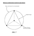
- FIG. 7 is a diagram illustrating an example minimum omnidirectional wavefront angle detector, according to some embodiments.
- the distance to the transmitter can be calculated based on received power compared to a known power (e.g., the power used to transmit), or utilizing other distance determination techniques.
- the distance to the transmitting device can be combined with an angle determined from the above-described process to determine device location.
- the distance to the transmitter can be measured by any other means, including measuring the difference in signal strength between sent and received signals, sonar, timing of signals, etc.
- each antenna unit automatically and autonomously calculates the phase of the incoming beacon.
- the Antennas (or a representative subset of antennas) then report the detected (or measured phases up to the master controller for analysis).
- the master controller monitors the detected phases over time, looking for a variance to sample for each antenna.
- FIG. 8 depicts a flow diagram illustrating an example process 800 for reducing computational requirements for sampling beacon signals received from wireless power receiver clients in a wireless power delivery environment, according to some embodiments. More specifically, example process 800 illustrates utilizing a previously computed inverse beacon directionality to transmit wireless power to the corresponding wireless power delivery client in a wireless power delivery environment.
- the inverse directionality can comprise an inverse phase of a received beacon signal as measured at each antenna of an array. As discussed herein, in some embodiments, the inverse directionality can be calculated by computing the complex conjugate of the measured beacon signal phases at each antenna.
- a wireless power transmission system such as, for example, wireless power transmission system 101 of FIG. 1 , can, among other functions perform the example process 800 .
- the wireless power transmission system determines a movement status mode of a wireless power receiver client in the wireless power delivery environment.
- the wireless power transmission system determines if the wireless power receiver client is in ‘static’ or ‘semi-static’ movement status mode. If so, at 814 , the wireless power transmission system identifies a previously computed inverse directionality of a beacon signal received from the wireless power receiver client and, at 822 , transmits wireless power to the wireless power receiver client in the direction indicated by the inverse directionality.
- FIG. 9 depicts a flow diagram illustrating an example process 900 for reducing computational requirements for sampling beacon signals received from wireless power receiver clients in a wireless power delivery environment, according to some embodiments. More specifically, example process 900 illustrates a process for detecting a static wireless power delivery device in a wireless power delivery environment and setting a corresponding movement status mode to ‘static’ or semi-static.
- a wireless power transmission system such as, for example, wireless power transmission system 101 of FIG. 1 , can, among other functions perform the example process 900 .
- the wireless power transmission system determines if the location of the wireless power receiver has changed since the last sample and, if so, at 918 , stores the samples (e.g., in a table) in association with, for example, an identifier associated with the wireless power receiver client. However, if the location of the wireless power receiver has changed then, at decision 920 , the wireless power transmission system determines if the increment (movement) count) is greater than some predetermined threshold. In some embodiments, the threshold can be set to a value (possibly dependent on the frequency at which beacon signals are received from a client) to determine if the wireless power receiver client has been static or semi-static movement-wise for a period of time. If not, at 922 , the wireless power transmission system increments the movement count.
- the wireless power transmission system sets the movement status mode associated with or corresponding to the wireless power receiver client to a ‘static’ or ‘semi-static’ mode.
- the wireless power transmission system calculates the directionality of the beacon signal received from the wireless power receiver client based on the samples. In some embodiments, calculating the directionality of the beacon signal comprises utilizing trig libraries to perform runtime calculations on the sampled beacon to calculate the directionality.
- the wireless power transmission system inverses the directionality of the beacon signal to determine the inverse directionality and, at 930 , stores the directionality and/or the inverse directionality in association with, for example, the identifier associated with the wireless power receiver client.
- the wireless power receiver client optionally adjusts the beacon scheduling to reflect that the wireless power receiver client is in a ‘static’ or ‘semi-static’ movement status mode.
- the wireless power receiver client in a retrodirective system it is imperative to transmit power to a known location of the wireless power receiver client. Accordingly, if the client is not moving, or not moving that much, then it may not need to beacon as frequently.
- FIG. 10 depicts a flow diagram illustrating an example process 1000 of simultaneously sampling a receiver's beacon across multiple antennas and reducing computational strain.
- the client receiver provides a beacon, at 1010 .
- the beacon is an omnidirectional wave that propagates outward until it intercepts multiple antennas on a charger array, at 1012 .
- the system may utilize trig libraries to perform runtime calculations, at 1018 . As the values are calculated, they may be stored within a local or remote database for future retrieval. In this manner the charger ‘learns’ over time, thereby continually reducing the required processing.
- FIG. 11 depicts a block diagram illustrating example components of a representative mobile device or tablet computer 1100 with a wireless power receiver or client in the form of a mobile (or smart) phone or tablet computer device, according to an embodiment.
- Various interfaces and modules are shown with reference to FIG. 11 , however, the mobile device or tablet computer does not require all of modules or functions for performing the functionality described herein.
- various components are not included and/or necessary for operation of the category controller. For example, components such as GPS radios, cellular radios, and accelerometers may not be included in the controllers to reduce costs and/or complexity. Additionally, components such as ZigBee radios and RFID transceivers, along with antennas, can populate the Printed Circuit Board.
- FIG. 12 depicts a diagrammatic representation of a machine, in the example form, of a computer system within which a set of instructions, for causing the machine to perform any one or more of the methodologies discussed herein, may be executed.
- the computer system includes a processor, memory, non-volatile memory, and an interface device.
- Various common components e.g., cache memory
- the computer system 1200 is intended to illustrate a hardware device on which any of the components depicted in the example of FIG. 1 (and any other components described in this specification) can be implemented.
- the computer system can be any radiating object or antenna array system.
- the computer system can be of any applicable known or convenient type.
- the components of the computer system can be coupled together via a bus or through some other known or convenient device.
- the processor may be, for example, a conventional microprocessor such as an Intel Pentium microprocessor or Motorola power PC microprocessor.
- Intel Pentium microprocessor or Motorola power PC microprocessor.
- machine-readable (storage) medium or “computer-readable (storage) medium” include any type of device that is accessible by the processor.
- the bus also couples the processor to the non-volatile memory and drive unit.
- the non-volatile memory is often a magnetic floppy or hard disk, a magnetic-optical disk, an optical disk, a read-only memory (ROM), such as a CD-ROM, EPROM, or EEPROM, a magnetic or optical card, or another form of storage for large amounts of data. Some of this data is often written, by a direct memory access process, into memory during execution of software in the computer 1200 .
- the non-volatile storage can be local, remote, or distributed.
- the non-volatile memory is optional because systems can be created with all applicable data available in memory.
- a typical computer system will usually include at least a processor, memory, and a device (e.g., a bus) coupling the memory to the processor.
- Software is typically stored in the non-volatile memory and/or the drive unit. Indeed, for large programs, it may not even be possible to store the entire program in the memory. Nevertheless, it should be understood that for software to run, if necessary, it is moved to a computer readable location appropriate for processing, and for illustrative purposes, that location is referred to as the memory in this paper. Even when software is moved to the memory for execution, the processor will typically make use of hardware registers to store values associated with the software, and local cache that, ideally, serves to speed up execution. As used herein, a software program is assumed to be stored at any known or convenient location (from non-volatile storage to hardware registers) when the software program is referred to as “implemented in a computer-readable medium”. A processor is considered to be “configured to execute a program” when at least one value associated with the program is stored in a register readable by the processor.
- the bus also couples the processor to the network interface device.
- the interface can include one or more of a modem or network interface. It will be appreciated that a modem or network interface can be considered to be part of the computer system.
- the interface can include an analog modem, isdn modem, cable modem, token ring interface, satellite transmission interface (e.g. “direct PC”), or other interfaces for coupling a computer system to other computer systems.
- the interface can include one or more input and/or output devices.
- the I/O devices can include, by way of example but not limitation, a keyboard, a mouse or other pointing device, disk drives, printers, a scanner, and other input and/or output devices, including a display device.
- the display device can include, by way of example but not limitation, a cathode ray tube (CRT), liquid crystal display (LCD), or some other applicable known or convenient display device.
- CTR cathode ray tube
- LCD liquid crystal display
- controllers of any devices not depicted in the example of FIG. 12 reside in the interface.
- the computer system 1200 can be controlled by operating system software that includes a file management system, such as a disk operating system.
- operating system software with associated file management system software is the family of operating systems known as Windows® from Microsoft Corporation of Redmond, Wash., and their associated file management systems.
- Windows® from Microsoft Corporation of Redmond, Wash.
- Windows® is the family of operating systems known as Windows® from Microsoft Corporation of Redmond, Wash.
- Linux operating system is the Linux operating system and its associated file management system.
- the file management system is typically stored in the non-volatile memory and/or drive unit and causes the processor to execute the various acts required by the operating system to input and output data and to store data in the memory, including storing files on the non-volatile memory and/or drive unit.
- the machine operates as a standalone device or may be connected (e.g., networked) to other machines.
- the machine may operate in the capacity of a server or a client machine in a client-server network environment or as a peer machine in a peer-to-peer (or distributed) network environment.
- machine-readable medium or machine-readable storage medium is shown in an exemplary embodiment to be a single medium, the term “machine-readable medium” and “machine-readable storage medium” should be taken to include a single medium or multiple media (e.g., a centralized or distributed database, and/or associated caches and servers) that store the one or more sets of instructions.
- the term “machine-readable medium” and “machine-readable storage medium” shall also be taken to include any medium that is capable of storing, encoding or carrying a set of instructions for execution by the machine and that cause the machine to perform any one or more of the methodologies of the presently disclosed technique and innovation.
- routines executed to implement the embodiments of the disclosure may be implemented as part of an operating system or a specific application, component, program, object, module or sequence of instructions referred to as “computer programs.”
- the computer programs typically comprise one or more instructions set at various times in various memory and storage devices in a computer, and that, when read and executed by one or more processing units or processors in a computer, cause the computer to perform operations to execute elements involving the various aspects of the disclosure.
- machine-readable storage media machine-readable media, or computer-readable (storage) media
- recordable type media such as volatile and non-volatile memory devices, floppy and other removable disks, hard disk drives, optical disks (e.g., Compact Disk Read-Only Memory (CD ROMS), Digital Versatile Disks, (DVDs), etc.), among others, and transmission type media such as digital and analog communication links.
- CD ROMS Compact Disk Read-Only Memory
- DVDs Digital Versatile Disks
- transmission type media such as digital and analog communication links.
- the words “comprise,” “comprising,” and the like are to be construed in an inclusive sense, as opposed to an exclusive or exhaustive sense; that is to say, in the sense of “including, but not limited to.”
- the terms “connected,” “coupled,” or any variant thereof means any connection or coupling, either direct or indirect, between two or more elements; the coupling of connection between the elements can be physical, logical, or a combination thereof.
- the words “herein,” “above,” “below,” and words of similar import when used in this application, shall refer to this application as a whole and not to any particular portions of this application.
- words in the above Detailed Description using the singular or plural number may also include the plural or singular number respectively.
- the word “or,” in reference to a list of two or more items, covers all of the following interpretations of the word: any of the items in the list, all of the items in the list, and any combination of the items in the list.
Landscapes
- Engineering & Computer Science (AREA)
- Computer Networks & Wireless Communication (AREA)
- Power Engineering (AREA)
- Signal Processing (AREA)
- Charge And Discharge Circuits For Batteries Or The Like (AREA)
- Mobile Radio Communication Systems (AREA)
- Physics & Mathematics (AREA)
- General Physics & Mathematics (AREA)
- Radar, Positioning & Navigation (AREA)
- Remote Sensing (AREA)
Abstract
Description
Claims (20)
Priority Applications (3)
| Application Number | Priority Date | Filing Date | Title |
|---|---|---|---|
| US15/196,769 US10199879B2 (en) | 2015-06-30 | 2016-06-29 | Techniques for facilitating beacon sampling efficiencies in wireless power delivery environments |
| US16/264,873 US11025095B2 (en) | 2015-06-30 | 2019-02-01 | Techniques for facilitating beacon sampling efficiencies in wireless power delivery environments |
| US17/242,305 US11831172B2 (en) | 2015-06-30 | 2021-04-28 | Techniques for facilitating beacon sampling efficiencies in wireless power delivery environments |
Applications Claiming Priority (2)
| Application Number | Priority Date | Filing Date | Title |
|---|---|---|---|
| US201562187190P | 2015-06-30 | 2015-06-30 | |
| US15/196,769 US10199879B2 (en) | 2015-06-30 | 2016-06-29 | Techniques for facilitating beacon sampling efficiencies in wireless power delivery environments |
Related Child Applications (1)
| Application Number | Title | Priority Date | Filing Date |
|---|---|---|---|
| US16/264,873 Continuation US11025095B2 (en) | 2015-06-30 | 2019-02-01 | Techniques for facilitating beacon sampling efficiencies in wireless power delivery environments |
Publications (2)
| Publication Number | Publication Date |
|---|---|
| US20170005531A1 US20170005531A1 (en) | 2017-01-05 |
| US10199879B2 true US10199879B2 (en) | 2019-02-05 |
Family
ID=57684478
Family Applications (4)
| Application Number | Title | Priority Date | Filing Date |
|---|---|---|---|
| US15/196,785 Active 2037-12-25 US10566845B2 (en) | 2015-06-30 | 2016-06-29 | Techniques for clock synchronization and control in wireless power delivery environments |
| US15/196,769 Active 2037-04-27 US10199879B2 (en) | 2015-06-30 | 2016-06-29 | Techniques for facilitating beacon sampling efficiencies in wireless power delivery environments |
| US16/264,873 Active 2036-08-03 US11025095B2 (en) | 2015-06-30 | 2019-02-01 | Techniques for facilitating beacon sampling efficiencies in wireless power delivery environments |
| US17/242,305 Active 2036-08-23 US11831172B2 (en) | 2015-06-30 | 2021-04-28 | Techniques for facilitating beacon sampling efficiencies in wireless power delivery environments |
Family Applications Before (1)
| Application Number | Title | Priority Date | Filing Date |
|---|---|---|---|
| US15/196,785 Active 2037-12-25 US10566845B2 (en) | 2015-06-30 | 2016-06-29 | Techniques for clock synchronization and control in wireless power delivery environments |
Family Applications After (2)
| Application Number | Title | Priority Date | Filing Date |
|---|---|---|---|
| US16/264,873 Active 2036-08-03 US11025095B2 (en) | 2015-06-30 | 2019-02-01 | Techniques for facilitating beacon sampling efficiencies in wireless power delivery environments |
| US17/242,305 Active 2036-08-23 US11831172B2 (en) | 2015-06-30 | 2021-04-28 | Techniques for facilitating beacon sampling efficiencies in wireless power delivery environments |
Country Status (1)
| Country | Link |
|---|---|
| US (4) | US10566845B2 (en) |
Cited By (2)
| Publication number | Priority date | Publication date | Assignee | Title |
|---|---|---|---|---|
| CN107678032A (en) * | 2017-07-21 | 2018-02-09 | 哈尔滨工程大学 | A kind of single beacon distance-measuring and positioning method based on virtual transceiving beacon |
| US12042043B2 (en) | 2020-06-11 | 2024-07-23 | Kohler Co. | Temperature tracking mirror |
Families Citing this family (22)
| Publication number | Priority date | Publication date | Assignee | Title |
|---|---|---|---|---|
| KR102601601B1 (en) * | 2016-04-19 | 2023-11-13 | 삼성전자주식회사 | Wireless Power Transceiver using phase and amplitude control algorithm and wireless power receiver |
| US10559983B2 (en) * | 2016-08-22 | 2020-02-11 | Ossia Inc. | Polarization adaptive wireless power transmission system |
| US10721604B2 (en) | 2016-12-19 | 2020-07-21 | Nxp B.V. | Method and system for operating a communications device that communicates via inductive coupling |
| US10390200B2 (en) | 2016-12-19 | 2019-08-20 | Nxp B.V. | Method and system for operating a communications device that communicates via inductive coupling |
| US10425131B2 (en) | 2017-04-06 | 2019-09-24 | Ossia Inc. | Beacon localization for a client device in wireless environment applications |
| US9942788B1 (en) * | 2017-05-19 | 2018-04-10 | Ossia Inc. | Systems and methods for determining operational status of functional components of a wireless signal transmission environment |
| JP2019009837A (en) * | 2017-06-20 | 2019-01-17 | ルネサスエレクトロニクス株式会社 | Wireless synchronization system and wireless device |
| US11615943B2 (en) | 2017-07-07 | 2023-03-28 | Advanced Energy Industries, Inc. | Inter-period control for passive power distribution of multiple electrode inductive plasma source |
| US10861677B2 (en) | 2017-07-07 | 2020-12-08 | Advanced Energy Industries, Inc. | Inter-period control system for plasma power delivery system and method of operating the same |
| US11651939B2 (en) | 2017-07-07 | 2023-05-16 | Advanced Energy Industries, Inc. | Inter-period control system for plasma power delivery system and method of operating same |
| EP3658923A4 (en) | 2017-07-26 | 2021-04-21 | Panoramic Power Ltd. | SYSTEM AND METHOD FOR CLOCK SYNCHRONIZATION OF A SELF-PROPELLED POWER SENSOR |
| US10512052B2 (en) | 2017-07-26 | 2019-12-17 | Panoramic Power Ltd. | Timing synchronization of self-powered power sensors and a central controller collecting samples therefrom |
| WO2019022808A1 (en) * | 2017-07-26 | 2019-01-31 | Panoramic Power Ltd. | Transmission of time stamps of samples of self-powered power |
| RU2658332C1 (en) | 2017-08-04 | 2018-06-20 | Самсунг Электроникс Ко., Лтд. | Wireless power transmission system for a multi-path environment |
| US10382098B2 (en) | 2017-09-25 | 2019-08-13 | Nxp B.V. | Method and system for operating a communications device that communicates via inductive coupling |
| US10720967B2 (en) * | 2017-09-25 | 2020-07-21 | Nxp B.V. | Method and system for operating a communications device that communicates via inductive coupling |
| US11025099B2 (en) | 2018-06-05 | 2021-06-01 | Avago Technologies International Sales Pte. Limited | Multipoint wireless power transfer system and method |
| US20200161889A1 (en) * | 2018-11-16 | 2020-05-21 | T-Mobile Usa, Inc. | Over-the-air wireless charging |
| US11101701B2 (en) | 2019-04-10 | 2021-08-24 | Ossia Inc. | Simplified wireless power receiver architecture |
| US11212023B2 (en) * | 2019-11-06 | 2021-12-28 | Microsoft Technology Licensing, Llc | Systems and methods for nodes communicating using a time-synchronized transport layer |
| US11593247B2 (en) * | 2021-06-03 | 2023-02-28 | Red Hat, Inc. | System performance evaluation and enhancement in a software-defined system |
| US11737044B1 (en) * | 2022-12-12 | 2023-08-22 | Ultralogic 6G, Llc | Mid-symbol timestamp point for precision synchronization in 5G and 6G |
Citations (14)
| Publication number | Priority date | Publication date | Assignee | Title |
|---|---|---|---|---|
| US20040145342A1 (en) | 2003-01-28 | 2004-07-29 | Lyon Geoff M. | Adaptive charger system and method |
| US20050136845A1 (en) * | 2003-09-22 | 2005-06-23 | Fujitsu Limited | Method and apparatus for location determination using mini-beacons |
| US20060113955A1 (en) | 2004-11-29 | 2006-06-01 | Patrick Nunally | Remote power charging of electronic devices |
| US20100181961A1 (en) | 2009-01-22 | 2010-07-22 | Qualcomm Incorporated | Adaptive power control for wireless charging |
| US20100315045A1 (en) | 2007-06-14 | 2010-12-16 | Omnilectric, Inc. | Wireless power transmission system |
| US20100323616A1 (en) | 2009-06-12 | 2010-12-23 | Qualcomm Incorporated | Devices for conveying wireless power and methods of operation thereof |
| US20110115432A1 (en) | 2009-11-17 | 2011-05-19 | Qualcomm Incorporated | Power management for electronic devices |
| US20110199935A1 (en) * | 2008-10-29 | 2011-08-18 | Kyocera Corporation | Radio communication system, transmission device, and communication signal transmission method |
| US20130214615A1 (en) | 2010-10-01 | 2013-08-22 | Nec Europe Ltd. | Method for colaborative energy transfer in a wireless network and corresponding wireless network |
| US8618770B2 (en) | 2009-08-24 | 2013-12-31 | Access Business Group International Llc | Wireless power distribution and control system |
| US20140217967A1 (en) | 2013-02-04 | 2014-08-07 | Ossia, Inc. | Systems and methods for optimally delivering pulsed wireless power |
| US20140375256A1 (en) | 2013-06-20 | 2014-12-25 | Samsung Electronics Co., Ltd. | Wireless power transmission system with ability to determine charging circumstances |
| US20160057613A1 (en) * | 2014-08-25 | 2016-02-25 | Telecommunication Systems, Inc. | Movement detecting beacon |
| US9979440B1 (en) * | 2013-07-25 | 2018-05-22 | Energous Corporation | Antenna tile arrangements configured to operate as one functional unit |
Family Cites Families (13)
| Publication number | Priority date | Publication date | Assignee | Title |
|---|---|---|---|---|
| US6963301B2 (en) * | 2002-08-19 | 2005-11-08 | G-Track Corporation | System and method for near-field electromagnetic ranging |
| US8805530B2 (en) * | 2007-06-01 | 2014-08-12 | Witricity Corporation | Power generation for implantable devices |
| TW200935858A (en) * | 2007-10-23 | 2009-08-16 | Agency Science Tech & Res | Communication device and method for synchronisation |
| US9420385B2 (en) * | 2009-12-21 | 2016-08-16 | Starkey Laboratories, Inc. | Low power intermittent messaging for hearing assistance devices |
| US9312977B1 (en) * | 2012-08-28 | 2016-04-12 | Bae Systems Information And Electronic Systems Integration Inc. | System and method to provide channel access synchronization without time-stamp exchange in time division multiple access (TDMA) multi-hop networks |
| US20140191568A1 (en) * | 2013-01-04 | 2014-07-10 | Mojo Mobility, Inc. | System and method for powering or charging multiple receivers wirelessly with a power transmitter |
| US9513609B2 (en) * | 2013-02-01 | 2016-12-06 | Nxp B.V. | Wireless communications using active modulation |
| US9793717B2 (en) * | 2013-08-23 | 2017-10-17 | Qualcomm Incorporated | Apparatus and method for non-compliant object detection |
| US9258713B2 (en) * | 2014-05-15 | 2016-02-09 | Cisco Technology, Inc. | Rogue wireless beacon device detection |
| US9622203B2 (en) * | 2014-08-19 | 2017-04-11 | WiZN Systems Pvt. Ltd | Low power communication system and method |
| US9577718B2 (en) * | 2014-11-19 | 2017-02-21 | Qualcomm Incorporated | Systems and methods for inductively coupled communications |
| US9673964B2 (en) * | 2015-02-18 | 2017-06-06 | Qualcomm Incorporated | Active load modulation in near field communication |
| JP6402819B2 (en) * | 2015-02-20 | 2018-10-10 | 富士通株式会社 | Power receiver and power transmission system |
-
2016
- 2016-06-29 US US15/196,785 patent/US10566845B2/en active Active
- 2016-06-29 US US15/196,769 patent/US10199879B2/en active Active
-
2019
- 2019-02-01 US US16/264,873 patent/US11025095B2/en active Active
-
2021
- 2021-04-28 US US17/242,305 patent/US11831172B2/en active Active
Patent Citations (14)
| Publication number | Priority date | Publication date | Assignee | Title |
|---|---|---|---|---|
| US20040145342A1 (en) | 2003-01-28 | 2004-07-29 | Lyon Geoff M. | Adaptive charger system and method |
| US20050136845A1 (en) * | 2003-09-22 | 2005-06-23 | Fujitsu Limited | Method and apparatus for location determination using mini-beacons |
| US20060113955A1 (en) | 2004-11-29 | 2006-06-01 | Patrick Nunally | Remote power charging of electronic devices |
| US20100315045A1 (en) | 2007-06-14 | 2010-12-16 | Omnilectric, Inc. | Wireless power transmission system |
| US20110199935A1 (en) * | 2008-10-29 | 2011-08-18 | Kyocera Corporation | Radio communication system, transmission device, and communication signal transmission method |
| US20100181961A1 (en) | 2009-01-22 | 2010-07-22 | Qualcomm Incorporated | Adaptive power control for wireless charging |
| US20100323616A1 (en) | 2009-06-12 | 2010-12-23 | Qualcomm Incorporated | Devices for conveying wireless power and methods of operation thereof |
| US8618770B2 (en) | 2009-08-24 | 2013-12-31 | Access Business Group International Llc | Wireless power distribution and control system |
| US20110115432A1 (en) | 2009-11-17 | 2011-05-19 | Qualcomm Incorporated | Power management for electronic devices |
| US20130214615A1 (en) | 2010-10-01 | 2013-08-22 | Nec Europe Ltd. | Method for colaborative energy transfer in a wireless network and corresponding wireless network |
| US20140217967A1 (en) | 2013-02-04 | 2014-08-07 | Ossia, Inc. | Systems and methods for optimally delivering pulsed wireless power |
| US20140375256A1 (en) | 2013-06-20 | 2014-12-25 | Samsung Electronics Co., Ltd. | Wireless power transmission system with ability to determine charging circumstances |
| US9979440B1 (en) * | 2013-07-25 | 2018-05-22 | Energous Corporation | Antenna tile arrangements configured to operate as one functional unit |
| US20160057613A1 (en) * | 2014-08-25 | 2016-02-25 | Telecommunication Systems, Inc. | Movement detecting beacon |
Non-Patent Citations (2)
| Title |
|---|
| Notification of Transmittal of the International Search Report and the Written Opinion of the International Searching Authority, or the Declaration received in International Application No. PCT/US2016/040319 dated Sep. 26, 2016, 12 pages. |
| Notification of Transmittal of the International Search Report and the Written Opinion of the International Searching Authority, or the Declaration received in International Application No. PCT/US2016/040343 dated Sep. 14, 2016, 11 pages. |
Cited By (2)
| Publication number | Priority date | Publication date | Assignee | Title |
|---|---|---|---|---|
| CN107678032A (en) * | 2017-07-21 | 2018-02-09 | 哈尔滨工程大学 | A kind of single beacon distance-measuring and positioning method based on virtual transceiving beacon |
| US12042043B2 (en) | 2020-06-11 | 2024-07-23 | Kohler Co. | Temperature tracking mirror |
Also Published As
| Publication number | Publication date |
|---|---|
| US20170005533A1 (en) | 2017-01-05 |
| US10566845B2 (en) | 2020-02-18 |
| US11831172B2 (en) | 2023-11-28 |
| US11025095B2 (en) | 2021-06-01 |
| US20210249910A1 (en) | 2021-08-12 |
| US20190165615A1 (en) | 2019-05-30 |
| US20170005531A1 (en) | 2017-01-05 |
Similar Documents
| Publication | Publication Date | Title |
|---|---|---|
| US11831172B2 (en) | Techniques for facilitating beacon sampling efficiencies in wireless power delivery environments | |
| US11024253B2 (en) | Techniques for statically tuning retro-directive wireless power transmission systems | |
| US10637289B2 (en) | Systems and methods for improved phase determinations in wireless power delivery environments | |
| US11742705B2 (en) | Predictive phase tracking in wireless power delivery environments | |
| US11316377B2 (en) | Wireless power transceivers for supplementing wireless power delivery and extending range | |
| US11817718B2 (en) | Polarization adaptive wireless power transmission system | |
| US10587155B2 (en) | Techniques for delivering retrodirective wireless power | |
| US20230198311A1 (en) | Wireless Power Receiver Clients With Dynamically Reconfigurable Antenna Configurations | |
| US10424971B2 (en) | Energy storage device for wireless environmental applications | |
| US20170194807A1 (en) | Techniques for charging beacon-free passive clients in multipath wireless power delivery environments | |
| US20210091604A1 (en) | Wafer-Level Integrated Antenna Array For Wireless Battery Charging | |
| US20190165599A1 (en) | Tone Power Scheduler For Wireless Environmental Applications |
Legal Events
| Date | Code | Title | Description |
|---|---|---|---|
| AS | Assignment |
Owner name: OSSIA INC., WASHINGTON Free format text: ASSIGNMENT OF ASSIGNORS INTEREST;ASSIGNORS:ZEINE, HATEM;MAYES, DALE;RENNEBERG, BENJAMIN;REEL/FRAME:039200/0576 Effective date: 20160629 |
|
| FEPP | Fee payment procedure |
Free format text: ENTITY STATUS SET TO UNDISCOUNTED (ORIGINAL EVENT CODE: BIG.); ENTITY STATUS OF PATENT OWNER: LARGE ENTITY Free format text: PETITION RELATED TO MAINTENANCE FEES GRANTED (ORIGINAL EVENT CODE: PTGR); ENTITY STATUS OF PATENT OWNER: LARGE ENTITY |
|
| STCF | Information on status: patent grant |
Free format text: PATENTED CASE |
|
| MAFP | Maintenance fee payment |
Free format text: PAYMENT OF MAINTENANCE FEE, 4TH YEAR, LARGE ENTITY (ORIGINAL EVENT CODE: M1551); ENTITY STATUS OF PATENT OWNER: LARGE ENTITY Year of fee payment: 4 |
|
| AS | Assignment |
Owner name: NERVE INVESTMENT SPV LTD, UNITED ARAB EMIRATES Free format text: NOTICE OF GRANT OF SECURITY INTEREST IN PATENTS;ASSIGNOR:OSSIA INC.;REEL/FRAME:062336/0628 Effective date: 20230106 Owner name: FARAH CAPITAL LMITED, BAHAMAS Free format text: NOTICE OF GRANT OF SECURITY INTEREST IN PATENTS;ASSIGNOR:OSSIA INC.;REEL/FRAME:062336/0628 Effective date: 20230106 |
|
| AS | Assignment |
Owner name: NERVE INVESTMENT SPV LTD, UNITED ARAB EMIRATES Free format text: CORRECTIVE ASSIGNMENT TO CORRECT THE ASSIGNEE NAME AND ZIP CODE OF CORRESPONDENCE ADDRESS PREVIOUSLY RECORDED AT REEL: 062336 FRAME: 0628. ASSIGNOR(S) HEREBY CONFIRMS THE ASSIGNMENT;ASSIGNOR:OSSIA INC.;REEL/FRAME:062926/0332 Effective date: 20230106 Owner name: FARAH CAPITAL LIMITED, BAHAMAS Free format text: CORRECTIVE ASSIGNMENT TO CORRECT THE ASSIGNEE NAME AND ZIP CODE OF CORRESPONDENCE ADDRESS PREVIOUSLY RECORDED AT REEL: 062336 FRAME: 0628. ASSIGNOR(S) HEREBY CONFIRMS THE ASSIGNMENT;ASSIGNOR:OSSIA INC.;REEL/FRAME:062926/0332 Effective date: 20230106 |
|
| AS | Assignment |
Owner name: TOYODA GOSEI., LTD, JAPAN Free format text: AMENDED AND RESTATED NOTICE OF GRANT OF SECURITY INTEREST IN PATENTS;ASSIGNOR:OSSIA INC.;REEL/FRAME:068369/0303 Effective date: 20230106 Owner name: NERVE INVESTMENT SPV LTD, AS SECURED PARTY, UNITED ARAB EMIRATES Free format text: AMENDED AND RESTATED NOTICE OF GRANT OF SECURITY INTEREST IN PATENTS;ASSIGNOR:OSSIA INC.;REEL/FRAME:068369/0303 Effective date: 20230106 Owner name: FARAH CAPITAL LIMITED, AS SECURED PARTY, BAHAMAS Free format text: AMENDED AND RESTATED NOTICE OF GRANT OF SECURITY INTEREST IN PATENTS;ASSIGNOR:OSSIA INC.;REEL/FRAME:068369/0303 Effective date: 20230106 |