US10199701B2 - Cathode for lithium air batter, lithium air battery including the same, and method of manufacturing cathode for lithium air battery - Google Patents
Cathode for lithium air batter, lithium air battery including the same, and method of manufacturing cathode for lithium air battery Download PDFInfo
- Publication number
- US10199701B2 US10199701B2 US15/161,538 US201615161538A US10199701B2 US 10199701 B2 US10199701 B2 US 10199701B2 US 201615161538 A US201615161538 A US 201615161538A US 10199701 B2 US10199701 B2 US 10199701B2
- Authority
- US
- United States
- Prior art keywords
- cathode
- substituted
- unsubstituted
- group
- ionic liquid
- Prior art date
- Legal status (The legal status is an assumption and is not a legal conclusion. Google has not performed a legal analysis and makes no representation as to the accuracy of the status listed.)
- Active, expires
Links
- 229910052744 lithium Inorganic materials 0.000 title claims abstract description 104
- WHXSMMKQMYFTQS-UHFFFAOYSA-N Lithium Chemical compound [Li] WHXSMMKQMYFTQS-UHFFFAOYSA-N 0.000 title claims abstract description 97
- 238000004519 manufacturing process Methods 0.000 title claims abstract description 37
- 229920000734 polysilsesquioxane polymer Polymers 0.000 claims abstract description 96
- 239000002608 ionic liquid Substances 0.000 claims abstract description 95
- 239000003575 carbonaceous material Substances 0.000 claims abstract description 47
- 239000011247 coating layer Substances 0.000 claims abstract description 39
- CSCPPACGZOOCGX-UHFFFAOYSA-N Acetone Chemical compound CC(C)=O CSCPPACGZOOCGX-UHFFFAOYSA-N 0.000 claims abstract description 27
- -1 nitrogen-containing cation Chemical class 0.000 claims description 31
- 239000002904 solvent Substances 0.000 claims description 25
- OKTJSMMVPCPJKN-UHFFFAOYSA-N Carbon Chemical compound [C] OKTJSMMVPCPJKN-UHFFFAOYSA-N 0.000 claims description 22
- 238000000034 method Methods 0.000 claims description 16
- 239000000203 mixture Substances 0.000 claims description 16
- 239000002243 precursor Substances 0.000 claims description 16
- OKKJLVBELUTLKV-UHFFFAOYSA-N Methanol Chemical compound OC OKKJLVBELUTLKV-UHFFFAOYSA-N 0.000 claims description 15
- 239000003792 electrolyte Substances 0.000 claims description 15
- 150000001768 cations Chemical group 0.000 claims description 14
- 239000011230 binding agent Substances 0.000 claims description 13
- QJGQUHMNIGDVPM-UHFFFAOYSA-N nitrogen group Chemical group [N] QJGQUHMNIGDVPM-UHFFFAOYSA-N 0.000 claims description 13
- 125000004435 hydrogen atom Chemical group [H]* 0.000 claims description 11
- 238000001035 drying Methods 0.000 claims description 10
- 239000002048 multi walled nanotube Substances 0.000 claims description 10
- 150000001450 anions Chemical class 0.000 claims description 9
- 125000002887 hydroxy group Chemical group [H]O* 0.000 claims description 9
- 125000003837 (C1-C20) alkyl group Chemical group 0.000 claims description 8
- 125000006736 (C6-C20) aryl group Chemical group 0.000 claims description 7
- ZXMGHDIOOHOAAE-UHFFFAOYSA-N 1,1,1-trifluoro-n-(trifluoromethylsulfonyl)methanesulfonamide Chemical compound FC(F)(F)S(=O)(=O)NS(=O)(=O)C(F)(F)F ZXMGHDIOOHOAAE-UHFFFAOYSA-N 0.000 claims description 7
- 125000003358 C2-C20 alkenyl group Chemical group 0.000 claims description 7
- NIXOWILDQLNWCW-UHFFFAOYSA-M acrylate group Chemical group C(C=C)(=O)[O-] NIXOWILDQLNWCW-UHFFFAOYSA-M 0.000 claims description 7
- CERQOIWHTDAKMF-UHFFFAOYSA-M methacrylate group Chemical group C(C(=C)C)(=O)[O-] CERQOIWHTDAKMF-UHFFFAOYSA-M 0.000 claims description 7
- XLYOFNOQVPJJNP-UHFFFAOYSA-N water Substances O XLYOFNOQVPJJNP-UHFFFAOYSA-N 0.000 claims description 7
- 239000011248 coating agent Substances 0.000 claims description 6
- 238000000576 coating method Methods 0.000 claims description 6
- 150000001875 compounds Chemical class 0.000 claims description 6
- 229910052739 hydrogen Inorganic materials 0.000 claims description 6
- 239000001257 hydrogen Substances 0.000 claims description 6
- FYZFRYWTMMVDLR-UHFFFAOYSA-M trimethyl(3-trimethoxysilylpropyl)azanium;chloride Chemical compound [Cl-].CO[Si](OC)(OC)CCC[N+](C)(C)C FYZFRYWTMMVDLR-UHFFFAOYSA-M 0.000 claims description 5
- 239000002041 carbon nanotube Substances 0.000 claims description 4
- 229910021393 carbon nanotube Inorganic materials 0.000 claims description 4
- 238000009831 deintercalation Methods 0.000 claims description 4
- 238000009830 intercalation Methods 0.000 claims description 4
- 125000000524 functional group Chemical group 0.000 claims description 3
- 150000003949 imides Chemical class 0.000 claims description 3
- 239000000758 substrate Substances 0.000 claims description 3
- 125000006376 (C3-C10) cycloalkyl group Chemical group 0.000 claims description 2
- 125000005371 silicon functional group Chemical group 0.000 claims description 2
- 230000003301 hydrolyzing effect Effects 0.000 claims 1
- 239000007784 solid electrolyte Substances 0.000 description 55
- 238000002360 preparation method Methods 0.000 description 50
- 239000012528 membrane Substances 0.000 description 44
- 230000000052 comparative effect Effects 0.000 description 25
- HBBGRARXTFLTSG-UHFFFAOYSA-N Lithium ion Chemical compound [Li+] HBBGRARXTFLTSG-UHFFFAOYSA-N 0.000 description 23
- 229910001416 lithium ion Inorganic materials 0.000 description 23
- QVGXLLKOCUKJST-UHFFFAOYSA-N atomic oxygen Chemical group [O] QVGXLLKOCUKJST-UHFFFAOYSA-N 0.000 description 22
- 229910052760 oxygen Inorganic materials 0.000 description 22
- 239000001301 oxygen Substances 0.000 description 21
- 238000004458 analytical method Methods 0.000 description 16
- 239000012071 phase Substances 0.000 description 14
- 239000013078 crystal Substances 0.000 description 13
- 229910003002 lithium salt Inorganic materials 0.000 description 13
- 159000000002 lithium salts Chemical class 0.000 description 13
- 239000003054 catalyst Substances 0.000 description 12
- 239000010408 film Substances 0.000 description 11
- 238000002411 thermogravimetry Methods 0.000 description 11
- QSZMZKBZAYQGRS-UHFFFAOYSA-N lithium;bis(trifluoromethylsulfonyl)azanide Chemical compound [Li+].FC(F)(F)S(=O)(=O)[N-]S(=O)(=O)C(F)(F)F QSZMZKBZAYQGRS-UHFFFAOYSA-N 0.000 description 10
- 229920003171 Poly (ethylene oxide) Polymers 0.000 description 9
- 239000004020 conductor Substances 0.000 description 9
- 150000002500 ions Chemical class 0.000 description 9
- 239000010410 layer Substances 0.000 description 9
- 239000000463 material Substances 0.000 description 9
- 229910052751 metal Inorganic materials 0.000 description 9
- 239000002184 metal Substances 0.000 description 9
- 239000003960 organic solvent Substances 0.000 description 9
- 125000003118 aryl group Chemical group 0.000 description 8
- 125000004104 aryloxy group Chemical group 0.000 description 8
- 229920001577 copolymer Polymers 0.000 description 8
- 229910003473 lithium bis(trifluoromethanesulfonyl)imide Inorganic materials 0.000 description 8
- RTZKZFJDLAIYFH-UHFFFAOYSA-N Diethyl ether Chemical compound CCOCC RTZKZFJDLAIYFH-UHFFFAOYSA-N 0.000 description 7
- PXHVJJICTQNCMI-UHFFFAOYSA-N Nickel Chemical compound [Ni] PXHVJJICTQNCMI-UHFFFAOYSA-N 0.000 description 7
- WYURNTSHIVDZCO-UHFFFAOYSA-N Tetrahydrofuran Chemical compound C1CCOC1 WYURNTSHIVDZCO-UHFFFAOYSA-N 0.000 description 7
- 239000000010 aprotic solvent Substances 0.000 description 7
- 229910052799 carbon Inorganic materials 0.000 description 7
- 239000011267 electrode slurry Substances 0.000 description 7
- 238000011156 evaluation Methods 0.000 description 7
- 239000011229 interlayer Substances 0.000 description 7
- 229910000664 lithium aluminum titanium phosphates (LATP) Inorganic materials 0.000 description 7
- 238000011068 loading method Methods 0.000 description 7
- WEVYAHXRMPXWCK-UHFFFAOYSA-N Acetonitrile Chemical compound CC#N WEVYAHXRMPXWCK-UHFFFAOYSA-N 0.000 description 6
- 238000006243 chemical reaction Methods 0.000 description 6
- 229920001940 conductive polymer Polymers 0.000 description 6
- 239000000178 monomer Substances 0.000 description 6
- 230000003647 oxidation Effects 0.000 description 6
- 238000007254 oxidation reaction Methods 0.000 description 6
- 229920000642 polymer Polymers 0.000 description 6
- 239000000126 substance Substances 0.000 description 6
- 238000005133 29Si NMR spectroscopy Methods 0.000 description 5
- XTHFKEDIFFGKHM-UHFFFAOYSA-N Dimethoxyethane Chemical compound COCCOC XTHFKEDIFFGKHM-UHFFFAOYSA-N 0.000 description 5
- 125000000753 cycloalkyl group Chemical group 0.000 description 5
- 238000009792 diffusion process Methods 0.000 description 5
- 238000007599 discharging Methods 0.000 description 5
- 238000002474 experimental method Methods 0.000 description 5
- 125000001072 heteroaryl group Chemical group 0.000 description 5
- 125000005842 heteroatom Chemical group 0.000 description 5
- FUJCRWPEOMXPAD-UHFFFAOYSA-N lithium oxide Chemical compound [Li+].[Li+].[O-2] FUJCRWPEOMXPAD-UHFFFAOYSA-N 0.000 description 5
- 239000011159 matrix material Substances 0.000 description 5
- 239000012046 mixed solvent Substances 0.000 description 5
- 239000011148 porous material Substances 0.000 description 5
- 239000002109 single walled nanotube Substances 0.000 description 5
- 125000000923 (C1-C30) alkyl group Chemical group 0.000 description 4
- SECXISVLQFMRJM-UHFFFAOYSA-N N-Methylpyrrolidone Chemical compound CN1CCCC1=O SECXISVLQFMRJM-UHFFFAOYSA-N 0.000 description 4
- 125000003545 alkoxy group Chemical group 0.000 description 4
- 229910052782 aluminium Inorganic materials 0.000 description 4
- XAGFODPZIPBFFR-UHFFFAOYSA-N aluminium Chemical compound [Al] XAGFODPZIPBFFR-UHFFFAOYSA-N 0.000 description 4
- 239000012298 atmosphere Substances 0.000 description 4
- 230000015572 biosynthetic process Effects 0.000 description 4
- 238000009833 condensation Methods 0.000 description 4
- 239000007789 gas Substances 0.000 description 4
- 239000002241 glass-ceramic Substances 0.000 description 4
- 238000010438 heat treatment Methods 0.000 description 4
- 125000005553 heteroaryloxy group Chemical group 0.000 description 4
- 125000000592 heterocycloalkyl group Chemical group 0.000 description 4
- 230000000670 limiting effect Effects 0.000 description 4
- 239000007788 liquid Substances 0.000 description 4
- 229910001947 lithium oxide Inorganic materials 0.000 description 4
- MCVFFRWZNYZUIJ-UHFFFAOYSA-M lithium;trifluoromethanesulfonate Chemical compound [Li+].[O-]S(=O)(=O)C(F)(F)F MCVFFRWZNYZUIJ-UHFFFAOYSA-M 0.000 description 4
- 239000011572 manganese Substances 0.000 description 4
- 229910052757 nitrogen Inorganic materials 0.000 description 4
- 239000012299 nitrogen atmosphere Substances 0.000 description 4
- 230000008569 process Effects 0.000 description 4
- 238000006722 reduction reaction Methods 0.000 description 4
- 239000007787 solid Substances 0.000 description 4
- 238000010183 spectrum analysis Methods 0.000 description 4
- 229910001220 stainless steel Inorganic materials 0.000 description 4
- ZUHZGEOKBKGPSW-UHFFFAOYSA-N tetraglyme Chemical compound COCCOCCOCCOCCOC ZUHZGEOKBKGPSW-UHFFFAOYSA-N 0.000 description 4
- LFQSCWFLJHTTHZ-UHFFFAOYSA-N Ethanol Chemical compound CCO LFQSCWFLJHTTHZ-UHFFFAOYSA-N 0.000 description 3
- LYCAIKOWRPUZTN-UHFFFAOYSA-N Ethylene glycol Chemical compound OCCO LYCAIKOWRPUZTN-UHFFFAOYSA-N 0.000 description 3
- KFZMGEQAYNKOFK-UHFFFAOYSA-N Isopropanol Chemical compound CC(C)O KFZMGEQAYNKOFK-UHFFFAOYSA-N 0.000 description 3
- 239000004743 Polypropylene Substances 0.000 description 3
- DNIAPMSPPWPWGF-UHFFFAOYSA-N Propylene glycol Chemical compound CC(O)CO DNIAPMSPPWPWGF-UHFFFAOYSA-N 0.000 description 3
- 238000002441 X-ray diffraction Methods 0.000 description 3
- JFDZBHWFFUWGJE-UHFFFAOYSA-N benzonitrile Chemical compound N#CC1=CC=CC=C1 JFDZBHWFFUWGJE-UHFFFAOYSA-N 0.000 description 3
- 229920001400 block copolymer Polymers 0.000 description 3
- 239000006182 cathode active material Substances 0.000 description 3
- 239000010949 copper Substances 0.000 description 3
- 239000006185 dispersion Substances 0.000 description 3
- 229910002804 graphite Inorganic materials 0.000 description 3
- 239000010439 graphite Substances 0.000 description 3
- 230000007062 hydrolysis Effects 0.000 description 3
- 238000006460 hydrolysis reaction Methods 0.000 description 3
- 229910010272 inorganic material Inorganic materials 0.000 description 3
- 239000011147 inorganic material Substances 0.000 description 3
- 238000001840 matrix-assisted laser desorption--ionisation time-of-flight mass spectrometry Methods 0.000 description 3
- 238000005259 measurement Methods 0.000 description 3
- 229910052759 nickel Inorganic materials 0.000 description 3
- 239000010955 niobium Substances 0.000 description 3
- 239000004745 nonwoven fabric Substances 0.000 description 3
- 229920001155 polypropylene Polymers 0.000 description 3
- 238000000425 proton nuclear magnetic resonance spectrum Methods 0.000 description 3
- 230000009467 reduction Effects 0.000 description 3
- 150000003839 salts Chemical class 0.000 description 3
- YLQBMQCUIZJEEH-UHFFFAOYSA-N tetrahydrofuran Natural products C=1C=COC=1 YLQBMQCUIZJEEH-UHFFFAOYSA-N 0.000 description 3
- CZDYPVPMEAXLPK-UHFFFAOYSA-N tetramethylsilane Chemical compound C[Si](C)(C)C CZDYPVPMEAXLPK-UHFFFAOYSA-N 0.000 description 3
- 239000010936 titanium Substances 0.000 description 3
- MYRTYDVEIRVNKP-UHFFFAOYSA-N 1,2-Divinylbenzene Chemical compound C=CC1=CC=CC=C1C=C MYRTYDVEIRVNKP-UHFFFAOYSA-N 0.000 description 2
- 238000005160 1H NMR spectroscopy Methods 0.000 description 2
- JWUJQDFVADABEY-UHFFFAOYSA-N 2-methyltetrahydrofuran Chemical compound CC1CCCO1 JWUJQDFVADABEY-UHFFFAOYSA-N 0.000 description 2
- YEJRWHAVMIAJKC-UHFFFAOYSA-N 4-Butyrolactone Chemical compound O=C1CCCO1 YEJRWHAVMIAJKC-UHFFFAOYSA-N 0.000 description 2
- IJGRMHOSHXDMSA-UHFFFAOYSA-N Atomic nitrogen Chemical compound N#N IJGRMHOSHXDMSA-UHFFFAOYSA-N 0.000 description 2
- KAKZBPTYRLMSJV-UHFFFAOYSA-N Butadiene Chemical compound C=CC=C KAKZBPTYRLMSJV-UHFFFAOYSA-N 0.000 description 2
- SOGAXMICEFXMKE-UHFFFAOYSA-N Butylmethacrylate Chemical compound CCCCOC(=O)C(C)=C SOGAXMICEFXMKE-UHFFFAOYSA-N 0.000 description 2
- RYGMFSIKBFXOCR-UHFFFAOYSA-N Copper Chemical compound [Cu] RYGMFSIKBFXOCR-UHFFFAOYSA-N 0.000 description 2
- LCGLNKUTAGEVQW-UHFFFAOYSA-N Dimethyl ether Chemical compound COC LCGLNKUTAGEVQW-UHFFFAOYSA-N 0.000 description 2
- IAZDPXIOMUYVGZ-UHFFFAOYSA-N Dimethylsulphoxide Chemical compound CS(C)=O IAZDPXIOMUYVGZ-UHFFFAOYSA-N 0.000 description 2
- IAYPIBMASNFSPL-UHFFFAOYSA-N Ethylene oxide Chemical compound C1CO1 IAYPIBMASNFSPL-UHFFFAOYSA-N 0.000 description 2
- 229910052693 Europium Inorganic materials 0.000 description 2
- OAKJQQAXSVQMHS-UHFFFAOYSA-N Hydrazine Chemical compound NN OAKJQQAXSVQMHS-UHFFFAOYSA-N 0.000 description 2
- UQSXHKLRYXJYBZ-UHFFFAOYSA-N Iron oxide Chemical compound [Fe]=O UQSXHKLRYXJYBZ-UHFFFAOYSA-N 0.000 description 2
- 229910008026 Li1+x+yAlxTi2-xSiyP3-yO12 Inorganic materials 0.000 description 2
- 229910008043 Li1+x+yAlxTi2−xSiyP3-yO12 Inorganic materials 0.000 description 2
- 229910006188 Li1+x+yAlxTi2−xSiyP3−yO12 Inorganic materials 0.000 description 2
- 229910001323 Li2O2 Inorganic materials 0.000 description 2
- 229910013375 LiC Inorganic materials 0.000 description 2
- 229910001559 LiC4F9SO3 Inorganic materials 0.000 description 2
- 229910000552 LiCF3SO3 Inorganic materials 0.000 description 2
- 229910013385 LiN(SO2C2F5)2 Inorganic materials 0.000 description 2
- 229910013406 LiN(SO2CF3)2 Inorganic materials 0.000 description 2
- 229910013436 LiN(SO3CF3)2 Inorganic materials 0.000 description 2
- 229910001290 LiPF6 Inorganic materials 0.000 description 2
- BAPJBEWLBFYGME-UHFFFAOYSA-N Methyl acrylate Chemical compound COC(=O)C=C BAPJBEWLBFYGME-UHFFFAOYSA-N 0.000 description 2
- VVQNEPGJFQJSBK-UHFFFAOYSA-N Methyl methacrylate Chemical compound COC(=O)C(C)=C VVQNEPGJFQJSBK-UHFFFAOYSA-N 0.000 description 2
- 238000005481 NMR spectroscopy Methods 0.000 description 2
- 239000002033 PVDF binder Substances 0.000 description 2
- KDLHZDBZIXYQEI-UHFFFAOYSA-N Palladium Chemical compound [Pd] KDLHZDBZIXYQEI-UHFFFAOYSA-N 0.000 description 2
- NBIIXXVUZAFLBC-UHFFFAOYSA-N Phosphoric acid Chemical compound OP(O)(O)=O NBIIXXVUZAFLBC-UHFFFAOYSA-N 0.000 description 2
- 239000004698 Polyethylene Substances 0.000 description 2
- GOOHAUXETOMSMM-UHFFFAOYSA-N Propylene oxide Chemical compound CC1CO1 GOOHAUXETOMSMM-UHFFFAOYSA-N 0.000 description 2
- 229910052772 Samarium Inorganic materials 0.000 description 2
- VYPSYNLAJGMNEJ-UHFFFAOYSA-N Silicium dioxide Chemical compound O=[Si]=O VYPSYNLAJGMNEJ-UHFFFAOYSA-N 0.000 description 2
- BQCADISMDOOEFD-UHFFFAOYSA-N Silver Chemical compound [Ag] BQCADISMDOOEFD-UHFFFAOYSA-N 0.000 description 2
- 229910002808 Si–O–Si Inorganic materials 0.000 description 2
- PPBRXRYQALVLMV-UHFFFAOYSA-N Styrene Chemical compound C=CC1=CC=CC=C1 PPBRXRYQALVLMV-UHFFFAOYSA-N 0.000 description 2
- 239000004809 Teflon Substances 0.000 description 2
- 229920006362 Teflon® Polymers 0.000 description 2
- 229910052771 Terbium Inorganic materials 0.000 description 2
- 229910052775 Thulium Inorganic materials 0.000 description 2
- GWEVSGVZZGPLCZ-UHFFFAOYSA-N Titan oxide Chemical compound O=[Ti]=O GWEVSGVZZGPLCZ-UHFFFAOYSA-N 0.000 description 2
- 229910052769 Ytterbium Inorganic materials 0.000 description 2
- 239000006230 acetylene black Substances 0.000 description 2
- NIXOWILDQLNWCW-UHFFFAOYSA-N acrylic acid group Chemical group C(C=C)(=O)O NIXOWILDQLNWCW-UHFFFAOYSA-N 0.000 description 2
- 125000001931 aliphatic group Chemical group 0.000 description 2
- 229910045601 alloy Inorganic materials 0.000 description 2
- 239000000956 alloy Substances 0.000 description 2
- 230000008901 benefit Effects 0.000 description 2
- 230000000903 blocking effect Effects 0.000 description 2
- 239000006229 carbon black Substances 0.000 description 2
- MVPPADPHJFYWMZ-UHFFFAOYSA-N chlorobenzene Chemical compound ClC1=CC=CC=C1 MVPPADPHJFYWMZ-UHFFFAOYSA-N 0.000 description 2
- 239000011651 chromium Substances 0.000 description 2
- 238000000748 compression moulding Methods 0.000 description 2
- 230000005494 condensation Effects 0.000 description 2
- 238000006482 condensation reaction Methods 0.000 description 2
- 239000002322 conducting polymer Substances 0.000 description 2
- 229910052802 copper Inorganic materials 0.000 description 2
- 239000008367 deionised water Substances 0.000 description 2
- 229910021641 deionized water Inorganic materials 0.000 description 2
- 238000003795 desorption Methods 0.000 description 2
- SBZXBUIDTXKZTM-UHFFFAOYSA-N diglyme Chemical compound COCCOCCOC SBZXBUIDTXKZTM-UHFFFAOYSA-N 0.000 description 2
- 125000002573 ethenylidene group Chemical group [*]=C=C([H])[H] 0.000 description 2
- JBTWLSYIZRCDFO-UHFFFAOYSA-N ethyl methyl carbonate Chemical compound CCOC(=O)OC JBTWLSYIZRCDFO-UHFFFAOYSA-N 0.000 description 2
- 239000005038 ethylene vinyl acetate Substances 0.000 description 2
- 229920000578 graft copolymer Polymers 0.000 description 2
- 125000005843 halogen group Chemical group 0.000 description 2
- AMWRITDGCCNYAT-UHFFFAOYSA-L hydroxy(oxo)manganese;manganese Chemical compound [Mn].O[Mn]=O.O[Mn]=O AMWRITDGCCNYAT-UHFFFAOYSA-L 0.000 description 2
- 239000011244 liquid electrolyte Substances 0.000 description 2
- 229910001540 lithium hexafluoroarsenate(V) Inorganic materials 0.000 description 2
- IIPYXGDZVMZOAP-UHFFFAOYSA-N lithium nitrate Chemical compound [Li+].[O-][N+]([O-])=O IIPYXGDZVMZOAP-UHFFFAOYSA-N 0.000 description 2
- MHCFAGZWMAWTNR-UHFFFAOYSA-M lithium perchlorate Chemical compound [Li+].[O-]Cl(=O)(=O)=O MHCFAGZWMAWTNR-UHFFFAOYSA-M 0.000 description 2
- 229910001486 lithium perchlorate Inorganic materials 0.000 description 2
- 229910001537 lithium tetrachloroaluminate Inorganic materials 0.000 description 2
- 229910001496 lithium tetrafluoroborate Inorganic materials 0.000 description 2
- QZIQJVCYUQZDIR-UHFFFAOYSA-N mechlorethamine hydrochloride Chemical compound Cl.ClCCN(C)CCCl QZIQJVCYUQZDIR-UHFFFAOYSA-N 0.000 description 2
- 238000002156 mixing Methods 0.000 description 2
- 239000004570 mortar (masonry) Substances 0.000 description 2
- LQNUZADURLCDLV-UHFFFAOYSA-N nitrobenzene Chemical compound [O-][N+](=O)C1=CC=CC=C1 LQNUZADURLCDLV-UHFFFAOYSA-N 0.000 description 2
- 239000006132 parent glass Substances 0.000 description 2
- 229910052698 phosphorus Inorganic materials 0.000 description 2
- 239000004014 plasticizer Substances 0.000 description 2
- BASFCYQUMIYNBI-UHFFFAOYSA-N platinum Chemical compound [Pt] BASFCYQUMIYNBI-UHFFFAOYSA-N 0.000 description 2
- 229920001200 poly(ethylene-vinyl acetate) Polymers 0.000 description 2
- 229920000573 polyethylene Polymers 0.000 description 2
- 239000005518 polymer electrolyte Substances 0.000 description 2
- 229920001343 polytetrafluoroethylene Polymers 0.000 description 2
- 239000004810 polytetrafluoroethylene Substances 0.000 description 2
- 229920002981 polyvinylidene fluoride Polymers 0.000 description 2
- 238000003825 pressing Methods 0.000 description 2
- 230000002829 reductive effect Effects 0.000 description 2
- 229920005989 resin Polymers 0.000 description 2
- 239000011347 resin Substances 0.000 description 2
- 230000002441 reversible effect Effects 0.000 description 2
- KZUNJOHGWZRPMI-UHFFFAOYSA-N samarium atom Chemical compound [Sm] KZUNJOHGWZRPMI-UHFFFAOYSA-N 0.000 description 2
- 229920006395 saturated elastomer Polymers 0.000 description 2
- 238000007086 side reaction Methods 0.000 description 2
- SCPYDCQAZCOKTP-UHFFFAOYSA-N silanol Chemical compound [SiH3]O SCPYDCQAZCOKTP-UHFFFAOYSA-N 0.000 description 2
- 229910052710 silicon Inorganic materials 0.000 description 2
- 229910052709 silver Inorganic materials 0.000 description 2
- 239000004332 silver Substances 0.000 description 2
- 239000010935 stainless steel Substances 0.000 description 2
- BHZCMUVGYXEBMY-UHFFFAOYSA-N trilithium;azanide Chemical compound [Li+].[Li+].[Li+].[NH2-] BHZCMUVGYXEBMY-UHFFFAOYSA-N 0.000 description 2
- 125000006735 (C1-C20) heteroalkyl group Chemical group 0.000 description 1
- 125000006649 (C2-C20) alkynyl group Chemical group 0.000 description 1
- 125000006737 (C6-C20) arylalkyl group Chemical group 0.000 description 1
- 125000006738 (C6-C20) heteroaryl group Chemical group 0.000 description 1
- 125000006742 (C6-C20) heteroarylalkyl group Chemical group 0.000 description 1
- DNIAPMSPPWPWGF-GSVOUGTGSA-N (R)-(-)-Propylene glycol Chemical compound C[C@@H](O)CO DNIAPMSPPWPWGF-GSVOUGTGSA-N 0.000 description 1
- DOYSIZKQWJYULQ-UHFFFAOYSA-N 1,1,2,2,2-pentafluoro-n-(1,1,2,2,2-pentafluoroethylsulfonyl)ethanesulfonamide Chemical compound FC(F)(F)C(F)(F)S(=O)(=O)NS(=O)(=O)C(F)(F)C(F)(F)F DOYSIZKQWJYULQ-UHFFFAOYSA-N 0.000 description 1
- SCYULBFZEHDVBN-UHFFFAOYSA-N 1,1-Dichloroethane Chemical compound CC(Cl)Cl SCYULBFZEHDVBN-UHFFFAOYSA-N 0.000 description 1
- BQCIDUSAKPWEOX-UHFFFAOYSA-N 1,1-Difluoroethene Chemical compound FC(F)=C BQCIDUSAKPWEOX-UHFFFAOYSA-N 0.000 description 1
- ZZXUZKXVROWEIF-UHFFFAOYSA-N 1,2-butylene carbonate Chemical compound CCC1COC(=O)O1 ZZXUZKXVROWEIF-UHFFFAOYSA-N 0.000 description 1
- WNXJIVFYUVYPPR-UHFFFAOYSA-N 1,3-dioxolane Chemical compound C1COCO1 WNXJIVFYUVYPPR-UHFFFAOYSA-N 0.000 description 1
- RYHBNJHYFVUHQT-UHFFFAOYSA-N 1,4-Dioxane Chemical compound C1COCCO1 RYHBNJHYFVUHQT-UHFFFAOYSA-N 0.000 description 1
- WGGLDBIZIQMEGH-UHFFFAOYSA-N 1-bromo-4-ethenylbenzene Chemical compound BrC1=CC=C(C=C)C=C1 WGGLDBIZIQMEGH-UHFFFAOYSA-N 0.000 description 1
- DURPTKYDGMDSBL-UHFFFAOYSA-N 1-butoxybutane Chemical compound CCCCOCCCC DURPTKYDGMDSBL-UHFFFAOYSA-N 0.000 description 1
- SMZOUWXMTYCWNB-UHFFFAOYSA-N 2-(2-methoxy-5-methylphenyl)ethanamine Chemical compound COC1=CC=C(C)C=C1CCN SMZOUWXMTYCWNB-UHFFFAOYSA-N 0.000 description 1
- GOXQRTZXKQZDDN-UHFFFAOYSA-N 2-Ethylhexyl acrylate Chemical compound CCCCC(CC)COC(=O)C=C GOXQRTZXKQZDDN-UHFFFAOYSA-N 0.000 description 1
- WDQMWEYDKDCEHT-UHFFFAOYSA-N 2-ethylhexyl 2-methylprop-2-enoate Chemical compound CCCCC(CC)COC(=O)C(C)=C WDQMWEYDKDCEHT-UHFFFAOYSA-N 0.000 description 1
- RUMACXVDVNRZJZ-UHFFFAOYSA-N 2-methylpropyl 2-methylprop-2-enoate Chemical compound CC(C)COC(=O)C(C)=C RUMACXVDVNRZJZ-UHFFFAOYSA-N 0.000 description 1
- KGIGUEBEKRSTEW-UHFFFAOYSA-N 2-vinylpyridine Chemical compound C=CC1=CC=CC=N1 KGIGUEBEKRSTEW-UHFFFAOYSA-N 0.000 description 1
- DXIJHCSGLOHNES-UHFFFAOYSA-N 3,3-dimethylbut-1-enylbenzene Chemical compound CC(C)(C)C=CC1=CC=CC=C1 DXIJHCSGLOHNES-UHFFFAOYSA-N 0.000 description 1
- WSQZNZLOZXSBHA-UHFFFAOYSA-N 3,8-dioxabicyclo[8.2.2]tetradeca-1(12),10,13-triene-2,9-dione Chemical compound O=C1OCCCCOC(=O)C2=CC=C1C=C2 WSQZNZLOZXSBHA-UHFFFAOYSA-N 0.000 description 1
- BJWMSGRKJIOCNR-UHFFFAOYSA-N 4-ethenyl-1,3-dioxolan-2-one Chemical compound C=CC1COC(=O)O1 BJWMSGRKJIOCNR-UHFFFAOYSA-N 0.000 description 1
- SBLRHMKNNHXPHG-UHFFFAOYSA-N 4-fluoro-1,3-dioxolan-2-one Chemical compound FC1COC(=O)O1 SBLRHMKNNHXPHG-UHFFFAOYSA-N 0.000 description 1
- WSSSPWUEQFSQQG-UHFFFAOYSA-N 4-methyl-1-pentene Chemical compound CC(C)CC=C WSSSPWUEQFSQQG-UHFFFAOYSA-N 0.000 description 1
- LBKMJZAKWQTTHC-UHFFFAOYSA-N 4-methyldioxolane Chemical compound CC1COOC1 LBKMJZAKWQTTHC-UHFFFAOYSA-N 0.000 description 1
- LLLVZDVNHNWSDS-UHFFFAOYSA-N 4-methylidene-3,5-dioxabicyclo[5.2.2]undeca-1(9),7,10-triene-2,6-dione Chemical compound C1(C2=CC=C(C(=O)OC(=C)O1)C=C2)=O LLLVZDVNHNWSDS-UHFFFAOYSA-N 0.000 description 1
- NLHHRLWOUZZQLW-UHFFFAOYSA-N Acrylonitrile Chemical compound C=CC#N NLHHRLWOUZZQLW-UHFFFAOYSA-N 0.000 description 1
- YBMNQXZAESRBNC-UHFFFAOYSA-N B([O-])([O-])[O-].B([O-])([O-])[O-].B([O-])([O-])[O-].B([O-])([O-])[O-].C(C)[N+](CCOC)(C)CC.C(C)[N+](CC)(C)CCOC.C(C)[N+](CC)(C)CCOC.C(C)[N+](CC)(C)CCOC.C(C)[N+](CC)(C)CCOC.C(C)[N+](CC)(C)CCOC.C(C)[N+](CC)(C)CCOC.C(C)[N+](CC)(C)CCOC.C(C)[N+](CC)(C)CCOC.C(C)[N+](CC)(C)CCOC.C(C)[N+](CC)(C)CCOC.C(C)[N+](CC)(C)CCOC Chemical compound B([O-])([O-])[O-].B([O-])([O-])[O-].B([O-])([O-])[O-].B([O-])([O-])[O-].C(C)[N+](CCOC)(C)CC.C(C)[N+](CC)(C)CCOC.C(C)[N+](CC)(C)CCOC.C(C)[N+](CC)(C)CCOC.C(C)[N+](CC)(C)CCOC.C(C)[N+](CC)(C)CCOC.C(C)[N+](CC)(C)CCOC.C(C)[N+](CC)(C)CCOC.C(C)[N+](CC)(C)CCOC.C(C)[N+](CC)(C)CCOC.C(C)[N+](CC)(C)CCOC.C(C)[N+](CC)(C)CCOC YBMNQXZAESRBNC-UHFFFAOYSA-N 0.000 description 1
- LSNNMFCWUKXFEE-UHFFFAOYSA-M Bisulfite Chemical compound OS([O-])=O LSNNMFCWUKXFEE-UHFFFAOYSA-M 0.000 description 1
- BTBUEUYNUDRHOZ-UHFFFAOYSA-N Borate Chemical compound [O-]B([O-])[O-] BTBUEUYNUDRHOZ-UHFFFAOYSA-N 0.000 description 1
- WCXXWLBPBJDQBK-UHFFFAOYSA-N CCN(C)CC.O=S(C(F)(F)F)(NS(C(F)(F)F)(=O)=O)=O Chemical compound CCN(C)CC.O=S(C(F)(F)F)(NS(C(F)(F)F)(=O)=O)=O WCXXWLBPBJDQBK-UHFFFAOYSA-N 0.000 description 1
- OYPRJOBELJOOCE-UHFFFAOYSA-N Calcium Chemical compound [Ca] OYPRJOBELJOOCE-UHFFFAOYSA-N 0.000 description 1
- 229920000049 Carbon (fiber) Polymers 0.000 description 1
- BVKZGUZCCUSVTD-UHFFFAOYSA-L Carbonate Chemical compound [O-]C([O-])=O BVKZGUZCCUSVTD-UHFFFAOYSA-L 0.000 description 1
- 229910052684 Cerium Inorganic materials 0.000 description 1
- VYZAMTAEIAYCRO-UHFFFAOYSA-N Chromium Chemical compound [Cr] VYZAMTAEIAYCRO-UHFFFAOYSA-N 0.000 description 1
- 229910018069 Cu3N Inorganic materials 0.000 description 1
- 102100021202 Desmocollin-1 Human genes 0.000 description 1
- OIFBSDVPJOWBCH-UHFFFAOYSA-N Diethyl carbonate Chemical compound CCOC(=O)OCC OIFBSDVPJOWBCH-UHFFFAOYSA-N 0.000 description 1
- MYMOFIZGZYHOMD-UHFFFAOYSA-N Dioxygen Chemical compound O=O MYMOFIZGZYHOMD-UHFFFAOYSA-N 0.000 description 1
- 229910052692 Dysprosium Inorganic materials 0.000 description 1
- 229920001780 ECTFE Polymers 0.000 description 1
- 229910052691 Erbium Inorganic materials 0.000 description 1
- JIGUQPWFLRLWPJ-UHFFFAOYSA-N Ethyl acrylate Chemical compound CCOC(=O)C=C JIGUQPWFLRLWPJ-UHFFFAOYSA-N 0.000 description 1
- KMTRUDSVKNLOMY-UHFFFAOYSA-N Ethylene carbonate Chemical compound O=C1OCCO1 KMTRUDSVKNLOMY-UHFFFAOYSA-N 0.000 description 1
- 229910005228 Ga2S3 Inorganic materials 0.000 description 1
- 229910052688 Gadolinium Inorganic materials 0.000 description 1
- GYHNNYVSQQEPJS-UHFFFAOYSA-N Gallium Chemical compound [Ga] GYHNNYVSQQEPJS-UHFFFAOYSA-N 0.000 description 1
- 229910005842 GeS2 Inorganic materials 0.000 description 1
- 229910052689 Holmium Inorganic materials 0.000 description 1
- 101000968043 Homo sapiens Desmocollin-1 Proteins 0.000 description 1
- 101000880960 Homo sapiens Desmocollin-3 Proteins 0.000 description 1
- XEEYBQQBJWHFJM-UHFFFAOYSA-N Iron Chemical compound [Fe] XEEYBQQBJWHFJM-UHFFFAOYSA-N 0.000 description 1
- 229910019271 La0.55Li0.35TiO3 Inorganic materials 0.000 description 1
- 229910000733 Li alloy Inorganic materials 0.000 description 1
- 229910020735 Li0.3La0.5TiO3 Inorganic materials 0.000 description 1
- 229910008190 Li1+x(M,Al,Ga)x(Ge1-yTiy)2-x(PO4)3 Inorganic materials 0.000 description 1
- 229910008187 Li1+x(M,Al,Ga)x(Ge1−yTiy)2−x(PO4)3 Inorganic materials 0.000 description 1
- 229910007959 Li1+x+y(Al,Ga)x(Ti,Ge)2−xSiyP3-yO12 Inorganic materials 0.000 description 1
- 229910008034 Li1+x+yAlx(Ti,Ge)2-xSiyP3-yO1 Inorganic materials 0.000 description 1
- 229910008020 Li1+x+yAlx(Ti,Ge)2−xSiyP3−yO1 Inorganic materials 0.000 description 1
- 229910006241 Li1+xHf2-xAlx(PO4)3 Inorganic materials 0.000 description 1
- 229910006231 Li1+xHf2−xAlx(PO4)3 Inorganic materials 0.000 description 1
- 229910009467 Li1.4Ti1.6Al0.4P3O12 Inorganic materials 0.000 description 1
- 229910008576 Li2O—Al2O3—TiO2—SiO2—P2O5 Inorganic materials 0.000 description 1
- 229910001216 Li2S Inorganic materials 0.000 description 1
- 229910012489 Li3Fe2P3O12 Inorganic materials 0.000 description 1
- 229910012814 Li3PO4.Li2S.SiS2 Inorganic materials 0.000 description 1
- 229910011250 Li3Zr2Si2PO12 Inorganic materials 0.000 description 1
- 229910012015 Li4NbP3O12 Inorganic materials 0.000 description 1
- 229910010685 Li5La3M2O12 Inorganic materials 0.000 description 1
- 229910010709 Li5La3Nb2O12 Inorganic materials 0.000 description 1
- 239000002224 Li5La3Nb2O12 Substances 0.000 description 1
- 229910010770 Li5TiP3O12 Inorganic materials 0.000 description 1
- 229910010799 Li5ZrP3O12 Inorganic materials 0.000 description 1
- 229910010640 Li6BaLa2Ta2O12 Inorganic materials 0.000 description 1
- 229910002984 Li7La3Zr2O12 Inorganic materials 0.000 description 1
- 229910013398 LiN(SO2CF2CF3)2 Inorganic materials 0.000 description 1
- 229910012305 LiPON Inorganic materials 0.000 description 1
- 229910012666 LiTi2P3O12 Inorganic materials 0.000 description 1
- FYYHWMGAXLPEAU-UHFFFAOYSA-N Magnesium Chemical compound [Mg] FYYHWMGAXLPEAU-UHFFFAOYSA-N 0.000 description 1
- PWHULOQIROXLJO-UHFFFAOYSA-N Manganese Chemical compound [Mn] PWHULOQIROXLJO-UHFFFAOYSA-N 0.000 description 1
- CERQOIWHTDAKMF-UHFFFAOYSA-N Methacrylic acid Chemical compound CC(=C)C(O)=O CERQOIWHTDAKMF-UHFFFAOYSA-N 0.000 description 1
- ZOKXTWBITQBERF-UHFFFAOYSA-N Molybdenum Chemical compound [Mo] ZOKXTWBITQBERF-UHFFFAOYSA-N 0.000 description 1
- FXHOOIRPVKKKFG-UHFFFAOYSA-N N,N-Dimethylacetamide Chemical compound CN(C)C(C)=O FXHOOIRPVKKKFG-UHFFFAOYSA-N 0.000 description 1
- 239000002228 NASICON Substances 0.000 description 1
- KKCBUQHMOMHUOY-UHFFFAOYSA-N Na2O Inorganic materials [O-2].[Na+].[Na+] KKCBUQHMOMHUOY-UHFFFAOYSA-N 0.000 description 1
- 229910020629 Na3Fe2P3O12 Inorganic materials 0.000 description 1
- 229910003249 Na3Zr2Si2PO12 Inorganic materials 0.000 description 1
- 229910020500 Na4NbP3O12 Inorganic materials 0.000 description 1
- 229910020525 Na5MSi4O12 Inorganic materials 0.000 description 1
- 229910020530 Na5TiP3O12 Inorganic materials 0.000 description 1
- 229910020529 Na5ZrP3O12 Inorganic materials 0.000 description 1
- 229920000557 Nafion® Polymers 0.000 description 1
- 229910052779 Neodymium Inorganic materials 0.000 description 1
- GSBKRFGXEJLVMI-UHFFFAOYSA-N Nervonyl carnitine Chemical compound CCC[N+](C)(C)C GSBKRFGXEJLVMI-UHFFFAOYSA-N 0.000 description 1
- 229910002656 O–Si–O Inorganic materials 0.000 description 1
- FVXHSJCDRRWIRE-UHFFFAOYSA-H P(=O)([O-])([O-])[O-].[Ge+2].[Al+3].[Li+].P(=O)([O-])([O-])[O-] Chemical compound P(=O)([O-])([O-])[O-].[Ge+2].[Al+3].[Li+].P(=O)([O-])([O-])[O-] FVXHSJCDRRWIRE-UHFFFAOYSA-H 0.000 description 1
- 229910019142 PO4 Inorganic materials 0.000 description 1
- 229920002845 Poly(methacrylic acid) Polymers 0.000 description 1
- 229920002319 Poly(methyl acrylate) Polymers 0.000 description 1
- 239000002202 Polyethylene glycol Substances 0.000 description 1
- 229920000265 Polyparaphenylene Polymers 0.000 description 1
- 239000004734 Polyphenylene sulfide Substances 0.000 description 1
- 229910052777 Praseodymium Inorganic materials 0.000 description 1
- KJTLSVCANCCWHF-UHFFFAOYSA-N Ruthenium Chemical compound [Ru] KJTLSVCANCCWHF-UHFFFAOYSA-N 0.000 description 1
- XUIMIQQOPSSXEZ-UHFFFAOYSA-N Silicon Chemical compound [Si] XUIMIQQOPSSXEZ-UHFFFAOYSA-N 0.000 description 1
- 229910021131 SiyP3−yO12 Inorganic materials 0.000 description 1
- 239000004115 Sodium Silicate Substances 0.000 description 1
- 229920002125 Sokalan® Polymers 0.000 description 1
- ATJFFYVFTNAWJD-UHFFFAOYSA-N Tin Chemical compound [Sn] ATJFFYVFTNAWJD-UHFFFAOYSA-N 0.000 description 1
- RTAQQCXQSZGOHL-UHFFFAOYSA-N Titanium Chemical compound [Ti] RTAQQCXQSZGOHL-UHFFFAOYSA-N 0.000 description 1
- 240000008042 Zea mays Species 0.000 description 1
- 235000005824 Zea mays ssp. parviglumis Nutrition 0.000 description 1
- 235000002017 Zea mays subsp mays Nutrition 0.000 description 1
- 229910021536 Zeolite Inorganic materials 0.000 description 1
- 239000011149 active material Substances 0.000 description 1
- 239000000853 adhesive Substances 0.000 description 1
- 230000001070 adhesive effect Effects 0.000 description 1
- 125000003342 alkenyl group Chemical group 0.000 description 1
- 125000000217 alkyl group Chemical group 0.000 description 1
- 125000002947 alkylene group Chemical group 0.000 description 1
- PNEYBMLMFCGWSK-UHFFFAOYSA-N aluminium oxide Inorganic materials [O-2].[O-2].[O-2].[Al+3].[Al+3] PNEYBMLMFCGWSK-UHFFFAOYSA-N 0.000 description 1
- 229910000147 aluminium phosphate Inorganic materials 0.000 description 1
- URZWHNFFWSYUMB-UHFFFAOYSA-B aluminum lithium silicon(4+) titanium(4+) tetraphosphate Chemical compound P(=O)([O-])([O-])[O-].[Si+4].[Ti+4].[Al+3].[Li+].P(=O)([O-])([O-])[O-].P(=O)([O-])([O-])[O-].P(=O)([O-])([O-])[O-] URZWHNFFWSYUMB-UHFFFAOYSA-B 0.000 description 1
- CVJYOKLQNGVTIS-UHFFFAOYSA-K aluminum;lithium;titanium(4+);phosphate Chemical compound [Li+].[Al+3].[Ti+4].[O-]P([O-])([O-])=O CVJYOKLQNGVTIS-UHFFFAOYSA-K 0.000 description 1
- 125000003277 amino group Chemical group 0.000 description 1
- NUZWLKWWNNJHPT-UHFFFAOYSA-N anthralin Chemical compound C1C2=CC=CC(O)=C2C(=O)C2=C1C=CC=C2O NUZWLKWWNNJHPT-UHFFFAOYSA-N 0.000 description 1
- 229910052787 antimony Inorganic materials 0.000 description 1
- WATWJIUSRGPENY-UHFFFAOYSA-N antimony atom Chemical compound [Sb] WATWJIUSRGPENY-UHFFFAOYSA-N 0.000 description 1
- 150000004945 aromatic hydrocarbons Chemical class 0.000 description 1
- 229910021383 artificial graphite Inorganic materials 0.000 description 1
- 229910052797 bismuth Inorganic materials 0.000 description 1
- JCXGWMGPZLAOME-UHFFFAOYSA-N bismuth atom Chemical compound [Bi] JCXGWMGPZLAOME-UHFFFAOYSA-N 0.000 description 1
- DQXBYHZEEUGOBF-UHFFFAOYSA-N but-3-enoic acid;ethene Chemical compound C=C.OC(=O)CC=C DQXBYHZEEUGOBF-UHFFFAOYSA-N 0.000 description 1
- 239000011575 calcium Substances 0.000 description 1
- 229910052791 calcium Inorganic materials 0.000 description 1
- 125000003739 carbamimidoyl group Chemical group C(N)(=N)* 0.000 description 1
- 125000004432 carbon atom Chemical group C* 0.000 description 1
- 239000004917 carbon fiber Substances 0.000 description 1
- 239000011852 carbon nanoparticle Substances 0.000 description 1
- 125000003178 carboxy group Chemical group [H]OC(*)=O 0.000 description 1
- 239000010406 cathode material Substances 0.000 description 1
- 239000000919 ceramic Substances 0.000 description 1
- GWXLDORMOJMVQZ-UHFFFAOYSA-N cerium Chemical compound [Ce] GWXLDORMOJMVQZ-UHFFFAOYSA-N 0.000 description 1
- 239000006231 channel black Substances 0.000 description 1
- 239000007806 chemical reaction intermediate Substances 0.000 description 1
- 229910052804 chromium Inorganic materials 0.000 description 1
- 239000004927 clay Substances 0.000 description 1
- 229910017052 cobalt Inorganic materials 0.000 description 1
- 239000010941 cobalt Substances 0.000 description 1
- GUTLYIVDDKVIGB-UHFFFAOYSA-N cobalt atom Chemical compound [Co] GUTLYIVDDKVIGB-UHFFFAOYSA-N 0.000 description 1
- 229910000428 cobalt oxide Inorganic materials 0.000 description 1
- MPMSMUBQXQALQI-UHFFFAOYSA-N cobalt phthalocyanine Chemical compound [Co+2].C12=CC=CC=C2C(N=C2[N-]C(C3=CC=CC=C32)=N2)=NC1=NC([C]1C=CC=CC1=1)=NC=1N=C1[C]3C=CC=CC3=C2[N-]1 MPMSMUBQXQALQI-UHFFFAOYSA-N 0.000 description 1
- IVMYJDGYRUAWML-UHFFFAOYSA-N cobalt(ii) oxide Chemical compound [Co]=O IVMYJDGYRUAWML-UHFFFAOYSA-N 0.000 description 1
- 239000002131 composite material Substances 0.000 description 1
- 235000005822 corn Nutrition 0.000 description 1
- 125000004093 cyano group Chemical group *C#N 0.000 description 1
- 125000004122 cyclic group Chemical group 0.000 description 1
- 125000000113 cyclohexyl group Chemical group [H]C1([H])C([H])([H])C([H])([H])C([H])(*)C([H])([H])C1([H])[H] 0.000 description 1
- 125000001511 cyclopentyl group Chemical group [H]C1([H])C([H])([H])C([H])([H])C([H])(*)C1([H])[H] 0.000 description 1
- FWLDHHJLVGRRHD-UHFFFAOYSA-N decyl prop-2-enoate Chemical compound CCCCCCCCCCOC(=O)C=C FWLDHHJLVGRRHD-UHFFFAOYSA-N 0.000 description 1
- QLVWOKQMDLQXNN-UHFFFAOYSA-N dibutyl carbonate Chemical compound CCCCOC(=O)OCCCC QLVWOKQMDLQXNN-UHFFFAOYSA-N 0.000 description 1
- 229960004132 diethyl ether Drugs 0.000 description 1
- QWNFEDACBXJNSI-UHFFFAOYSA-N diethyl(methyl)azanium;trifluoromethanesulfonate Chemical compound CC[NH+](C)CC.[O-]S(=O)(=O)C(F)(F)F QWNFEDACBXJNSI-UHFFFAOYSA-N 0.000 description 1
- HNCXPJFPCAYUGJ-UHFFFAOYSA-N dilithium bis(trifluoromethylsulfonyl)azanide Chemical compound [Li+].[Li+].FC(F)(F)S(=O)(=O)[N-]S(=O)(=O)C(F)(F)F.FC(F)(F)S(=O)(=O)[N-]S(=O)(=O)C(F)(F)F HNCXPJFPCAYUGJ-UHFFFAOYSA-N 0.000 description 1
- XUCJHNOBJLKZNU-UHFFFAOYSA-M dilithium;hydroxide Chemical compound [Li+].[Li+].[OH-] XUCJHNOBJLKZNU-UHFFFAOYSA-M 0.000 description 1
- IEJIGPNLZYLLBP-UHFFFAOYSA-N dimethyl carbonate Chemical compound COC(=O)OC IEJIGPNLZYLLBP-UHFFFAOYSA-N 0.000 description 1
- 239000004205 dimethyl polysiloxane Substances 0.000 description 1
- KDFUZGIURBWOQI-UHFFFAOYSA-N dimethyl(propyl)azanium trifluoromethanesulfonate Chemical compound CCC[NH+](C)C.[O-]S(=O)(=O)C(F)(F)F KDFUZGIURBWOQI-UHFFFAOYSA-N 0.000 description 1
- HNPSIPDUKPIQMN-UHFFFAOYSA-N dioxosilane;oxo(oxoalumanyloxy)alumane Chemical compound O=[Si]=O.O=[Al]O[Al]=O HNPSIPDUKPIQMN-UHFFFAOYSA-N 0.000 description 1
- 229910001882 dioxygen Inorganic materials 0.000 description 1
- VUPKGFBOKBGHFZ-UHFFFAOYSA-N dipropyl carbonate Chemical compound CCCOC(=O)OCCC VUPKGFBOKBGHFZ-UHFFFAOYSA-N 0.000 description 1
- KPUWHANPEXNPJT-UHFFFAOYSA-N disiloxane Chemical class [SiH3]O[SiH3] KPUWHANPEXNPJT-UHFFFAOYSA-N 0.000 description 1
- 229960002311 dithranol Drugs 0.000 description 1
- KBQHZAAAGSGFKK-UHFFFAOYSA-N dysprosium atom Chemical compound [Dy] KBQHZAAAGSGFKK-UHFFFAOYSA-N 0.000 description 1
- 230000002708 enhancing effect Effects 0.000 description 1
- UYAHIZSMUZPPFV-UHFFFAOYSA-N erbium Chemical compound [Er] UYAHIZSMUZPPFV-UHFFFAOYSA-N 0.000 description 1
- SUPCQIBBMFXVTL-UHFFFAOYSA-N ethyl 2-methylprop-2-enoate Chemical compound CCOC(=O)C(C)=C SUPCQIBBMFXVTL-UHFFFAOYSA-N 0.000 description 1
- CYEDOLFRAIXARV-UHFFFAOYSA-N ethyl propyl carbonate Chemical compound CCCOC(=O)OCC CYEDOLFRAIXARV-UHFFFAOYSA-N 0.000 description 1
- 229920006242 ethylene acrylic acid copolymer Polymers 0.000 description 1
- 229920000840 ethylene tetrafluoroethylene copolymer Polymers 0.000 description 1
- OGPBJKLSAFTDLK-UHFFFAOYSA-N europium atom Chemical compound [Eu] OGPBJKLSAFTDLK-UHFFFAOYSA-N 0.000 description 1
- 239000000835 fiber Substances 0.000 description 1
- 239000000706 filtrate Substances 0.000 description 1
- UQSQSQZYBQSBJZ-UHFFFAOYSA-N fluorosulfonic acid Chemical compound OS(F)(=O)=O UQSQSQZYBQSBJZ-UHFFFAOYSA-N 0.000 description 1
- UIWYJDYFSGRHKR-UHFFFAOYSA-N gadolinium atom Chemical compound [Gd] UIWYJDYFSGRHKR-UHFFFAOYSA-N 0.000 description 1
- 229910052733 gallium Inorganic materials 0.000 description 1
- 230000014509 gene expression Effects 0.000 description 1
- 239000011521 glass Substances 0.000 description 1
- 230000009477 glass transition Effects 0.000 description 1
- PCHJSUWPFVWCPO-UHFFFAOYSA-N gold Chemical compound [Au] PCHJSUWPFVWCPO-UHFFFAOYSA-N 0.000 description 1
- 229910052737 gold Inorganic materials 0.000 description 1
- 239000010931 gold Substances 0.000 description 1
- 125000004051 hexyl group Chemical group [H]C([H])([H])C([H])([H])C([H])([H])C([H])([H])C([H])([H])C([H])([H])* 0.000 description 1
- KJZYNXUDTRRSPN-UHFFFAOYSA-N holmium atom Chemical compound [Ho] KJZYNXUDTRRSPN-UHFFFAOYSA-N 0.000 description 1
- 150000007857 hydrazones Chemical class 0.000 description 1
- 150000002430 hydrocarbons Chemical group 0.000 description 1
- 239000012535 impurity Substances 0.000 description 1
- 229910052738 indium Inorganic materials 0.000 description 1
- APFVFJFRJDLVQX-UHFFFAOYSA-N indium atom Chemical compound [In] APFVFJFRJDLVQX-UHFFFAOYSA-N 0.000 description 1
- 230000002401 inhibitory effect Effects 0.000 description 1
- 229910052500 inorganic mineral Inorganic materials 0.000 description 1
- 239000003273 ketjen black Substances 0.000 description 1
- 150000002576 ketones Chemical class 0.000 description 1
- 239000006233 lamp black Substances 0.000 description 1
- 150000002641 lithium Chemical class 0.000 description 1
- 229910001547 lithium hexafluoroantimonate(V) Inorganic materials 0.000 description 1
- 229910052749 magnesium Inorganic materials 0.000 description 1
- 239000011777 magnesium Substances 0.000 description 1
- 229910052748 manganese Inorganic materials 0.000 description 1
- 238000004949 mass spectrometry Methods 0.000 description 1
- 230000007246 mechanism Effects 0.000 description 1
- 125000005395 methacrylic acid group Chemical group 0.000 description 1
- VNWKTOKETHGBQD-UHFFFAOYSA-N methane Chemical compound C VNWKTOKETHGBQD-UHFFFAOYSA-N 0.000 description 1
- 125000002496 methyl group Chemical group [H]C([H])([H])* 0.000 description 1
- RCIJMMSZBQEWKW-UHFFFAOYSA-N methyl propan-2-yl carbonate Chemical compound COC(=O)OC(C)C RCIJMMSZBQEWKW-UHFFFAOYSA-N 0.000 description 1
- KKQAVHGECIBFRQ-UHFFFAOYSA-N methyl propyl carbonate Chemical compound CCCOC(=O)OC KKQAVHGECIBFRQ-UHFFFAOYSA-N 0.000 description 1
- 239000011707 mineral Substances 0.000 description 1
- 229910052750 molybdenum Inorganic materials 0.000 description 1
- 239000011733 molybdenum Substances 0.000 description 1
- QNILTEGFHQSKFF-UHFFFAOYSA-N n-propan-2-ylprop-2-enamide Chemical compound CC(C)NC(=O)C=C QNILTEGFHQSKFF-UHFFFAOYSA-N 0.000 description 1
- 229910021382 natural graphite Inorganic materials 0.000 description 1
- QEFYFXOXNSNQGX-UHFFFAOYSA-N neodymium atom Chemical compound [Nd] QEFYFXOXNSNQGX-UHFFFAOYSA-N 0.000 description 1
- 229910000480 nickel oxide Inorganic materials 0.000 description 1
- 229910052758 niobium Inorganic materials 0.000 description 1
- GUCVJGMIXFAOAE-UHFFFAOYSA-N niobium atom Chemical group [Nb] GUCVJGMIXFAOAE-UHFFFAOYSA-N 0.000 description 1
- 125000000449 nitro group Chemical group [O-][N+](*)=O 0.000 description 1
- 238000011022 operating instruction Methods 0.000 description 1
- 229910052762 osmium Inorganic materials 0.000 description 1
- SYQBFIAQOQZEGI-UHFFFAOYSA-N osmium atom Chemical compound [Os] SYQBFIAQOQZEGI-UHFFFAOYSA-N 0.000 description 1
- 150000002924 oxiranes Chemical class 0.000 description 1
- GNRSAWUEBMWBQH-UHFFFAOYSA-N oxonickel Chemical compound [Ni]=O GNRSAWUEBMWBQH-UHFFFAOYSA-N 0.000 description 1
- RVTZCBVAJQQJTK-UHFFFAOYSA-N oxygen(2-);zirconium(4+) Chemical compound [O-2].[O-2].[Zr+4] RVTZCBVAJQQJTK-UHFFFAOYSA-N 0.000 description 1
- 229910052763 palladium Inorganic materials 0.000 description 1
- PNJWIWWMYCMZRO-UHFFFAOYSA-N pent‐4‐en‐2‐one Natural products CC(=O)CC=C PNJWIWWMYCMZRO-UHFFFAOYSA-N 0.000 description 1
- 125000001997 phenyl group Chemical group [H]C1=C([H])C([H])=C(*)C([H])=C1[H] 0.000 description 1
- 229910052697 platinum Inorganic materials 0.000 description 1
- 229920001490 poly(butyl methacrylate) polymer Polymers 0.000 description 1
- 229920002493 poly(chlorotrifluoroethylene) Polymers 0.000 description 1
- 229920000435 poly(dimethylsiloxane) Polymers 0.000 description 1
- 229920001483 poly(ethyl methacrylate) polymer Polymers 0.000 description 1
- 229920003229 poly(methyl methacrylate) Polymers 0.000 description 1
- 239000004584 polyacrylic acid Substances 0.000 description 1
- 239000005023 polychlorotrifluoroethylene (PCTFE) polymer Substances 0.000 description 1
- 229920000120 polyethyl acrylate Polymers 0.000 description 1
- 229920001223 polyethylene glycol Polymers 0.000 description 1
- 239000004926 polymethyl methacrylate Substances 0.000 description 1
- 229920005672 polyolefin resin Polymers 0.000 description 1
- 229920000069 polyphenylene sulfide Polymers 0.000 description 1
- 229920001451 polypropylene glycol Polymers 0.000 description 1
- 239000000843 powder Substances 0.000 description 1
- PUDIUYLPXJFUGB-UHFFFAOYSA-N praseodymium atom Chemical compound [Pr] PUDIUYLPXJFUGB-UHFFFAOYSA-N 0.000 description 1
- 239000010970 precious metal Substances 0.000 description 1
- 238000012545 processing Methods 0.000 description 1
- 239000000047 product Substances 0.000 description 1
- 125000001436 propyl group Chemical group [H]C([*])([H])C([H])([H])C([H])([H])[H] 0.000 description 1
- RUOJZAUFBMNUDX-UHFFFAOYSA-N propylene carbonate Chemical compound CC1COC(=O)O1 RUOJZAUFBMNUDX-UHFFFAOYSA-N 0.000 description 1
- 230000001681 protective effect Effects 0.000 description 1
- 229910052761 rare earth metal Inorganic materials 0.000 description 1
- 229910052703 rhodium Inorganic materials 0.000 description 1
- 239000010948 rhodium Substances 0.000 description 1
- MHOVAHRLVXNVSD-UHFFFAOYSA-N rhodium atom Chemical compound [Rh] MHOVAHRLVXNVSD-UHFFFAOYSA-N 0.000 description 1
- 229910052707 ruthenium Inorganic materials 0.000 description 1
- 239000010703 silicon Substances 0.000 description 1
- 239000000377 silicon dioxide Substances 0.000 description 1
- 229910052708 sodium Inorganic materials 0.000 description 1
- 239000011734 sodium Substances 0.000 description 1
- NTHWMYGWWRZVTN-UHFFFAOYSA-N sodium silicate Chemical compound [Na+].[Na+].[O-][Si]([O-])=O NTHWMYGWWRZVTN-UHFFFAOYSA-N 0.000 description 1
- 229910052911 sodium silicate Inorganic materials 0.000 description 1
- 239000007790 solid phase Substances 0.000 description 1
- 239000007858 starting material Substances 0.000 description 1
- 229920003048 styrene butadiene rubber Polymers 0.000 description 1
- 238000006467 substitution reaction Methods 0.000 description 1
- IAHFWCOBPZCAEA-UHFFFAOYSA-N succinonitrile Chemical compound N#CCCC#N IAHFWCOBPZCAEA-UHFFFAOYSA-N 0.000 description 1
- HXJUTPCZVOIRIF-UHFFFAOYSA-N sulfolane Chemical compound O=S1(=O)CCCC1 HXJUTPCZVOIRIF-UHFFFAOYSA-N 0.000 description 1
- 229910052717 sulfur Inorganic materials 0.000 description 1
- 229910052715 tantalum Inorganic materials 0.000 description 1
- GUVRBAGPIYLISA-UHFFFAOYSA-N tantalum atom Chemical compound [Ta] GUVRBAGPIYLISA-UHFFFAOYSA-N 0.000 description 1
- JBQYATWDVHIOAR-UHFFFAOYSA-N tellanylidenegermanium Chemical compound [Te]=[Ge] JBQYATWDVHIOAR-UHFFFAOYSA-N 0.000 description 1
- GZCRRIHWUXGPOV-UHFFFAOYSA-N terbium atom Chemical compound [Tb] GZCRRIHWUXGPOV-UHFFFAOYSA-N 0.000 description 1
- 229920005992 thermoplastic resin Polymers 0.000 description 1
- 229920001187 thermosetting polymer Polymers 0.000 description 1
- 239000010409 thin film Substances 0.000 description 1
- FRNOGLGSGLTDKL-UHFFFAOYSA-N thulium atom Chemical compound [Tm] FRNOGLGSGLTDKL-UHFFFAOYSA-N 0.000 description 1
- 229910052718 tin Inorganic materials 0.000 description 1
- 229910052719 titanium Inorganic materials 0.000 description 1
- 239000004408 titanium dioxide Substances 0.000 description 1
- 125000005369 trialkoxysilyl group Chemical group 0.000 description 1
- WFKWXMTUELFFGS-UHFFFAOYSA-N tungsten Chemical compound [W] WFKWXMTUELFFGS-UHFFFAOYSA-N 0.000 description 1
- 229910052721 tungsten Inorganic materials 0.000 description 1
- 239000010937 tungsten Substances 0.000 description 1
- 229910052720 vanadium Inorganic materials 0.000 description 1
- GPPXJZIENCGNKB-UHFFFAOYSA-N vanadium Chemical compound [V]#[V] GPPXJZIENCGNKB-UHFFFAOYSA-N 0.000 description 1
- LEONUFNNVUYDNQ-UHFFFAOYSA-N vanadium atom Chemical compound [V] LEONUFNNVUYDNQ-UHFFFAOYSA-N 0.000 description 1
- 230000004580 weight loss Effects 0.000 description 1
- NAWDYIZEMPQZHO-UHFFFAOYSA-N ytterbium Chemical compound [Yb] NAWDYIZEMPQZHO-UHFFFAOYSA-N 0.000 description 1
- 239000010457 zeolite Substances 0.000 description 1
- 229910001928 zirconium oxide Inorganic materials 0.000 description 1
Images


Classifications
-
- H—ELECTRICITY
- H01—ELECTRIC ELEMENTS
- H01M—PROCESSES OR MEANS, e.g. BATTERIES, FOR THE DIRECT CONVERSION OF CHEMICAL ENERGY INTO ELECTRICAL ENERGY
- H01M12/00—Hybrid cells; Manufacture thereof
- H01M12/08—Hybrid cells; Manufacture thereof composed of a half-cell of a fuel-cell type and a half-cell of the secondary-cell type
-
- H—ELECTRICITY
- H01—ELECTRIC ELEMENTS
- H01M—PROCESSES OR MEANS, e.g. BATTERIES, FOR THE DIRECT CONVERSION OF CHEMICAL ENERGY INTO ELECTRICAL ENERGY
- H01M4/00—Electrodes
- H01M4/86—Inert electrodes with catalytic activity, e.g. for fuel cells
- H01M4/96—Carbon-based electrodes
-
- Y—GENERAL TAGGING OF NEW TECHNOLOGICAL DEVELOPMENTS; GENERAL TAGGING OF CROSS-SECTIONAL TECHNOLOGIES SPANNING OVER SEVERAL SECTIONS OF THE IPC; TECHNICAL SUBJECTS COVERED BY FORMER USPC CROSS-REFERENCE ART COLLECTIONS [XRACs] AND DIGESTS
- Y02—TECHNOLOGIES OR APPLICATIONS FOR MITIGATION OR ADAPTATION AGAINST CLIMATE CHANGE
- Y02E—REDUCTION OF GREENHOUSE GAS [GHG] EMISSIONS, RELATED TO ENERGY GENERATION, TRANSMISSION OR DISTRIBUTION
- Y02E60/00—Enabling technologies; Technologies with a potential or indirect contribution to GHG emissions mitigation
- Y02E60/10—Energy storage using batteries
-
- Y02E60/128—
Definitions
- the present disclosure relates to a cathode for lithium air batteries, lithium air batteries including the same, and methods of manufacturing the cathodes for lithium air batteries.
- Lithium air batteries can include an anode which is capable of intercalating and deintercalating lithium, a cathode which oxidizes and reduces oxygen form the air, and a lithium ion conductive medium between the cathodes and the anodes.
- lithium is used as an anode, and air is used as a cathode active material, and thus the cathode active material does not need to be stored in the battery. Because the cathode active material does not need to be stored in the battery, a lithium air battery with a high capacity may be obtained.
- Lithium air batteries have a very high theoretical energy density per unit weight, e.g., 3,500 watt-hours per kilogram (Wh/kg) or greater, which is approximately 10 times greater than that of lithium ion batteries.
- a lithium air battery uses, as an electrolyte, a liquid electrolyte or a solid electrolyte.
- the solid electrolyte has a lower ionic conductivity than the liquid electrolyte, and has poorer wettability at an interface thereof with a carbonaceous conductive material or the like.
- the solid electrolyte is squeezed out by lithium oxide formed in an air electrode during battery discharging and charging. It is difficult for the squeezed-out solid electrolyte to return and accordingly, reversible charging and discharging processes may be difficult.
- a lithium air battery operates at a high temperature, e.g., 60° C. or higher, there are problems with thermal stability and reversible charge/discharge characteristics.
- a cathode for a lithium air battery that provides enhanced thermal stability and charge/discharge characteristics at high temperatures.
- a lithium air battery including the cathode.
- a cathode for a lithium air battery includes a carbonaceous material including: a carbonaceous core; and a coating layer on the carbonaceous core, wherein the coating layer includes an amorphous polysilsesquioxane ionic liquid having a viscosity of at least 0.2 milliPascal-seconds as measured as a 10 weight percent solution in acetone at 30° C. at 30° C.
- a lithium air battery includes the cathode; an anode capable of intercalating and deintercalating lithium; and an electrolyte disposed between the cathode and the anode.
- a method of manufacturing a cathode for a lithium air battery includes: obtaining a mixture of a polysilsesquioxane precursor and a first solvent; drying the mixture of the polysilsesquioxane precursor and the first solvent to obtain an amorphous polysilsesquioxane ionic liquid; adding a carbonaceous core and a second solvent to the amorphous polysilsesquioxane ionic liquid to provide a solution; drying the solution to manufacture a carbonaceous material including a carbonaceous core, and a coating layer on the carbonaceous core, wherein the coating layer includes an amorphous polysilsesquioxane ionic liquid having a viscosity of at least 0.2 milliPascal-seconds as measured as a 10 weight percent solution in acetone at 30° C.; and disposing the carbonaceous material and a binder on a substrate to manufacture the cathode.
- FIG. 1 is a schematic view illustrating a structure of a lithium air battery according to an embodiment
- FIG. 2 is a graph of intensity (arbitrary units, a.u.) versus chemical shift (parts per million, ppm) relative to tetramethylsilane and illustrates the results of proton nuclear magnetic resonance ( 1 H NMR) of an amorphous polysilsesquioxane ionic liquid prepared according to Preparation Example 1;
- FIG. 3 is a graph of intensity (arbitrary units, a.u.) versus chemical shift (parts per million, ppm) relative to tetramethylsilane and illustrates the results of silicon nuclear magnetic resonance ( 29 Si NMR) analysis of the amorphous polysilsesquioxane ionic liquid of Preparation Example 1;
- FIG. 4 is a graph intensity (counts per second, c/s) versus diffraction angle (degrees two-theta) showing the results of X-ray diffraction (XRD) analysis of the amorphous polysilsesquioxane ionic liquid of Preparation Example 1;
- FIG. 5 is a graph of intensity (arbitrary units, a.u.) versus mass to charge ratio (M/Z) showing the results of matrix assisted laser desorption/ionization time-of-flight (MALDI-TOF) analysis of the amorphous polysilsesquioxane ionic liquid of Preparation Example 1;
- MALDI-TOF matrix assisted laser desorption/ionization time-of-flight
- FIG. 6 is a photograph of a phase of the amorphous polysilsesquioxane ionic liquid of Preparation Example 1 at 60° C.;
- FIG. 7A is a graph of weight percent (%) versus temperature (° C.), showing the results of thermogravimetric analysis (TGA) of a carbon-based material and an ionic liquid respectively included in cathodes for a lithium air battery that are manufactured according to Example 1 and Comparative Example 3, in which the TGA experiment is performed in a nitrogen atmosphere at a heating rate of 5° C./min;
- TGA thermogravimetric analysis
- FIG. 7B is a graph of weight percent (%) versus temperature (° C.) showing the results of TGA analysis of a carbonaceous material and an ionic liquid respectively included in the cathodes for a lithium air battery that are manufactured according to Example 1 and Comparative Example 3, in which the TGA experiment is performed in an atmospheric atmosphere and at a heating rate of 5° C./min; and
- FIG. 8 is a graph of coulombic efficiency (discharge capacity divided by charge capacity, percent (%)) versus cycle number showing a Coulombic efficiency and cyclability of each of the lithium air batteries manufactured according to Examples 5 and 6 and Comparative Examples 4 and 5.
- first,” “second,” “third,” etc. may be used herein to describe various elements, components, regions, layers, and/or sections, these elements, components, regions, layers, and/or sections should not be limited by these terms. These terms are only used to distinguish one element, component, region, layer, or section from another element, component, region, layer, or section. Thus, “a first element,” “component,” “region,” “layer,” or “section” discussed below could be termed a second element, component, region, layer, or section without departing from the teachings herein.
- At least one is not to be construed as limiting “a” or “an.” “At least one” is not to be construed as limiting “a” or “an.” It will be further understood that the terms “comprises” and/or “comprising,” or “includes” and/or “including” when used in this specification, specify the presence of stated features, regions, integers, steps, operations, elements, and/or components, and do not preclude the presence or addition of one or more other features, regions, integers, steps, operations, elements, components, and/or groups thereof.
- spatially relative terms such as “beneath,” “below,” “lower,” “above,” “upper” and the like, may be used herein for ease of description to describe one element or feature's relationship to another element(s) or feature(s) as illustrated in the figures. It will be understood that the spatially relative terms are intended to encompass different orientations of the device in use or operation in addition to the orientation depicted in the figures. For example, if the device in the figures is turned over, elements described as “below” or “beneath” other elements or features would then be oriented “above” the other elements or features. Thus, the exemplary term “below” can encompass both an orientation of above and below. The device may be otherwise oriented (rotated 90 degrees or at other orientations) and the spatially relative descriptors used herein interpreted accordingly.
- “About” or “approximately” as used herein is inclusive of the stated value and means within an acceptable range of deviation for the particular value as determined by one of ordinary skill in the art, considering the measurement in question and the error associated with measurement of the particular quantity (i.e., the limitations of the measurement system). For example, “about” can mean within one or more standard deviations, or within ⁇ 30%, 20%, 10%, or 5% of the stated value.
- Exemplary embodiments are described herein with reference to cross section illustrations that are schematic illustrations of idealized embodiments. As such, variations from the shapes of the illustrations as a result, for example, of manufacturing techniques and/or tolerances, are to be expected. Thus, embodiments described herein should not be construed as limited to the particular shapes of regions as illustrated herein but are to include deviations in shapes that result, for example, from manufacturing. For example, a region illustrated or described as flat may, typically, have rough and/or nonlinear features. Moreover, sharp angles that are illustrated may be rounded. Thus, the regions illustrated in the figures are schematic in nature and their shapes are not intended to illustrate the precise shape of a region and are not intended to limit the scope of the present claims.
- amorphous as used herein includes both “amorphous” and “amorphous-like”.
- a cathode for a lithium air battery a lithium air battery including the cathode, and methods of manufacturing the cathode will be disclosed in further detail. These embodiments are for illustrative purposes only and are not intended to limit the scope of disclosed embodiments.
- a cathode for a lithium air battery includes a carbonaceous material including: a carbonaceous core; and a coating layer on the carbonaceous core, wherein the coating layer comprises an amorphous polysilsesquioxane ionic liquid having a viscosity (n) of at least 0.2 milliPascal-seconds (mPa.$), when measured in an aprotic solvent at 30° C., for example wherein the amorphous polysilsesquioxane ionic liquid has a viscosity of at least 0.2 milliPascal-seconds as measured as a 10 weight percent solution in acetone at 30° C.
- the amorphous polysilsesquioxane ionic liquid may have a viscosity (n) of about 0.1 mPa ⁇ s to about 2000 mPa ⁇ s, about 0.2 mPa ⁇ s to about 1200 mPa ⁇ s, or about 1.0 mPa ⁇ s to about 600 mPa ⁇ s, in an aprotic solvent at 30° C., or as measured as a 10 weight percent solution in acetone at 30° C.
- Non-limiting examples of the aprotic solvent include acetone, ethanol, isopropyl alcohol, ethylene glycol, propylene glycol, N-methyl-2-pyrrolidinone (NMP), and glyme. Acetone as the aprotic solvent is specifically mentioned.
- the viscosity (n) of the amorphous polysilsesquioxane ionic liquid may be measured using a LVDV-II+Pro Cone/Plate viscometer equipped with a CPE-40 cone spindle, manufactured by Brookfield Engineering Laboratories, USA.
- the LVDV-II+Pro Cone/Plate viscometer is calibrated with certified viscosity standards 5 cP and B29 at 25 ⁇ 0.2° C. according to the operating instructions and the viscosity of a sample may be measured at 30 ⁇ 0.2° C.
- the polysilsesquioxane ionic liquid may be amorphous.
- the polysilsesquioxane ionic liquid may have the viscosity (n) range described above at 30° C. in an aprotic solvent. While not wanting to be bound by theory, it is understood that the amorphous polysilsesquioxane ionic liquid has a sufficiently stable O—Si—O—Si bond in the form of an oligomer and/or a polymer and thus may form a coating layer having improved structural stability on the carbonaceous core.
- a lithium air battery including the amorphous polysilsesquioxane ionic liquid may have enhanced thermal stability and charge/discharge characteristics at high temperatures.
- the amorphous polysilsesquioxane ionic liquid may be a ladder-type amorphous polysilsesquioxane ionic liquid.
- the ladder-type amorphous polysilsesquioxane ionic liquid is understood to provide stable O—Si—O—Si bonds formed as a long double chain structure with O—Si—O crosslinks between the chains, and thus has improved structural stability.
- the ladder-type amorphous polysilsesquioxane ionic liquid has improved solubility with respect to an organic solvent and thus has improved processability and accordingly, may easily form a satisfactory coating layer.
- a lithium air battery including the amorphous polysilsesquioxane ionic liquid may have enhanced thermal stability and improved high temperature charge/discharge characteristics.
- the amorphous polysilsesquioxane ionic liquid may be represented by Formula 1.
- n may be an integer from 1 to 20;
- each of R 1 to R 7 may be independently hydrogen, a hydroxyl group, a substituted or unsubstituted organic functional group, a substituted or unsubstituted silicon functional group, or a combination thereof;
- X + may be a quaternary nitrogen-containing cation functional group
- Y ⁇ may be (CF 3 SO 2 ) 2 N ⁇ , (C 2 F 5 SO 2 ) 2 N ⁇ , CF 3 SO 3 ⁇ , an anion represented by Formula 1-1, or a combination thereof.
- x may be an integer from 0 to 15;
- y may be an integer from 0 to 1000;
- n may be an integer of 1 or more.
- the amorphous polysilsesquioxane ionic liquid of Formula 1 has the number n of —O—Si—O—Si— repeating units within the range described above, and while not wanting to be bound by theory, it is understood that these repeating units facilitate the formation of a stable coating layer having an appropriate viscosity on the carbonaceous core and may effectively control a side reaction with an electrolyte.
- X + may be a quaternary nitrogen-containing cation functional group.
- the quaternary nitrogen-containing cation functional group (X + ) may include an aliphatic quaternary nitrogen-containing cation functional group, an aromatic quaternary nitrogen-containing cation functional group, or a cyclic quaternary nitrogen-containing cation functional group, but is not limited thereto.
- the quaternary nitrogen-containing cation functional group (X + ) is chemically stable in a reaction with an electrolyte.
- Y ⁇ may be (CF 3 SO 2 ) 2 N ⁇ , (C 2 F 5 SO 2 ) 2 N ⁇ , CF 3 SO 3 ⁇ , the anion of Formula 1-1, or a combination thereof.
- the anion functional group imparts an appropriate viscosity to the coating layer and may act as a plasticizer that facilitates processing of the coating layer.
- the quaternary nitrogen-containing cation functional group may include a quaternary nitrogen-containing cation of Formulas 2A to 2F, or a combination thereof:
- each R′ may independently be a hydrogen atom, a hydroxyl group, a substituted or unsubstituted C 1 -C 20 alkyl group, a substituted or unsubstituted C 6 -C 20 aryl group, a substituted or unsubstituted C 2 -C 20 alkenyl group, a substituted or unsubstituted C 3 -C 10 cycloalkyl group, a substituted or unsubstituted C 1 -C 20 alkyleneoxide group, a substituted or unsubstituted acrylate group, or a substituted or unsubstituted methacrylate group.
- the quaternary nitrogen-containing cation functional group of Formulas 2A to 2F may facilitate hydrolysis-condensation and is more chemically stable in a reaction with an electrolyte.
- a lithium air battery including the quaternary nitrogen-containing cation functional group may have enhanced thermal stability and charge/discharge characteristics at high temperatures.
- each of R 1 to R 7 may be independently a hydroxyl group, a substituted or unsubstituted C 1 -C 20 alkyl group, a substituted or unsubstituted C 2 -C 20 alkenyl group, a substituted or unsubstituted C 3 -C 20 cycloalkyl group, a substituted or unsubstituted C 6 -C 20 aryl group, a substituted or unsubstituted C 1 -C 20 alkyleneoxide group, a substituted or unsubstituted acrylate group, a substituted or unsubstituted methacrylate group, or a combination thereof.
- a lithium air battery including the quaternary nitrogen-containing cation functional group of Formula 2 may have enhanced thermal stability and improved high temperature charge/discharge characteristics.
- the amorphous polysilsesquioxane ionic liquid may be represented by Formula:
- n 1 may be an integer from 1 to 20,
- Y 1 ⁇ may be (CF 3 SO 2 ) 2 N ⁇ , (C 2 F 5 SO 2 ) 2 N ⁇ , CF 3 SO 3 ⁇ , the anion of Formula 1-1 wherein x is an integer from 0 to 15, y is an integer from 0 to 1000, and m is 1 or 2, or a combination thereof.
- the amorphous polysilsesquioxane ionic liquid of Formula 3 may form a stable coating layer having a more appropriate viscosity at high temperatures.
- a lithium air battery including such ionic liquid may have enhanced thermal stability and improved charge/discharge characteristics.
- the amorphous polysilsesquioxane ionic liquid may have a weight average molecular weight (Mw) of greater than about 1,800 Daltons to about 5,000 Daltons.
- Mw weight average molecular weight
- the weight average molecular weight Mw of the amorphous polysilsesquioxane ionic liquid may be from about 1,000 Daltons to about 5,000 Daltons, from about 1,500 Daltons to about 4,000 Daltons, or from about 2,000 Daltons to about 3,000 Daltons.
- the amorphous polysilsesquioxane ionic liquid may have a gel phase at 60° C.
- gel phase means a state that maintains a physical form at room temperature, does not flow in a steady state, and intentionally includes a low molecular weight material that is liquid at room temperature, such as water or an organic solvent.
- Low molecular weight means a weight average molecular weight of less than 5,000 Daltons (Da), e.g., about 58 Da to about 5000 Da, or about 60 Da to about 2500 Da.
- the amorphous polysilsesquioxane ionic liquid having the weight average molecular weight within the range described above may be amorphous and have a gel phase or a waxy solid phase at 60° C. or higher.
- the coating layer may effectively protect the carbonaceous core, not be decomposed in a reaction with an electrolyte, and provide sufficient stability.
- a lithium air battery including the coating layer may have enhanced thermal stability and improved high temperature charge/discharge characteristics.
- the amount of the coating layer may be from about 1 weight percent (wt %) to about 30 wt %, based on the total weight of the cathode.
- the amount of the coating layer may be from about 1 wt % to about 20 wt %, for example, from about 1 wt % to about 10 wt %, based on the total weight of the cathode.
- a coating layer having an appropriate thickness may be formed.
- the coating layer may be in the form of a continuous coating or an island coating.
- the shape of the coating layer is not limited to the above examples.
- the carbonaceous material may include carbon nanotubes.
- the carbon nanotubes have a one-dimensional carbon structure may provide superior cyclability relative to carbon nanoparticles, such as carbon black and acetylene black.
- the carbon nanotubes may include porous multi-walled carbon nanotubes (MWCNTs).
- MWCNTs single-walled carbon nanotubes
- SWCNTs may be in the form of a bundle in which several SWCNTs are entangled with each other or bent, making it difficult to form a film-type coating layer using the SWCNTs.
- the MWCNTs may form a film-type coating layer more easily than the SWCNTs and have pores, which may increase a contact area with an electrolyte.
- the MWCNTs may facilitate supply and diffusion of oxygen in the cathode and may provide a space to which a product generated during battery charging and discharging is attached.
- a lithium air battery including such carbonaceous material may have enhanced charge/discharge characteristics.
- the porous MWCNTs may have a Brunauer-Emmett-Teller (BET) specific surface area of about 300 meters squared per gram (m 2 /g) or more, for example, about 400 m 2 /g or more, for example, about 500 m 2 /g or more, for example, about 600 m 2 /g or more, for example, about 700 m 2 /g or more.
- BET Brunauer-Emmett-Teller
- the porous MWCNTs may have a BET specific surface area of about 300 m 2 /g to about 3000 m 2 /g, about 500 m 2 /g to about 2500 m 2 /g, or about 700 m 2 /g to about 2000 m 2 /g.
- the cathode may further include a binder.
- the binder may increase the adhesive strength of a support to the carbonaceous material.
- the binder may include a thermoplastic resin or a thermosetting resin.
- the binder include polyethylene, polypropylene, polytetrafluoroethylene (PTFE), polyvinylidene fluoride (PVDF), styrene-butadiene rubber, a tetrafluoroethylene-perfluoroalkylvinylether copolymer, a vinylidene fluoride-hexafluoropropylene copolymer, a vinylidene fluoride-chlorotrifluoroethylene copolymer, an ethylene-tetrafluoroethylene copolymer, polychlorotrifluoroethylene, a vinylidene fluoride-pentafluoropropylene copolymer, a propylene-tetrafluoroethylene copolymer, an ethylene-chlorotrifluoroethylene copolymer, a vinylidene fluoride-hexafluoropropylene-tetrafluor
- a lithium air battery according to another embodiment may include the cathode described above, an anode capable of intercalating and deintercalating lithium, and an electrolyte disposed between the cathode and the anode.
- the cathode may include the carbonaceous material described above.
- the cathode including the carbonaceous material described above may have enhanced thermal stability, improved coulombic efficiency, and improved charge/discharge characteristics such as improved high temperature cyclability.
- the cathode may further include a solvent and a lithium salt to form a composite cathode.
- the solvent may include an organic solvent, ionic liquid, an oligomer, or a combination thereof, but is not limited to the above examples.
- any suitable solvent that is liquid at room temperature (25° C.) may be used.
- the organic solvent may include an ether solvent, a carbonate solvent, an ester solvent, a ketone solvent, or a combination thereof.
- the organic solvent may comprise propylene carbonate, ethylene carbonate, fluoroethylene carbonate, vinyl ethylene carbonate, butylene carbonate, dimethyl carbonate, diethyl carbonate, methyl ethyl carbonate, methyl propyl carbonate, ethyl propyl carbonate, methyl isopropyl carbonate, dipropyl carbonate, dibutyl carbonate, benzonitrile, acetonitrile, tetrahydrofuran, 2-methyltetrahydrofuran, ⁇ -butyrolactone, dioxolane, 4-methyldioxolane, dimethylacetamide, dimethyl sulfoxide, dioxane, 1,2-dimethoxyethane, sulfolane, dichloroethane, chlorobenzene, nitrobenzene, succinonitrile, diethylene glycol dimethyl ether (DEGDME), tetraethylene glycol dimethyl ether (TEGDME), polyethylene glycol dimethyl
- the ionic liquid may be represented by Formula a or b:
- R a2 and R a3 are each independently hydrogen, a substituted or unsubstituted C 1 -C 30 alkyl group, a substituted or unsubstituted C 1 -C 30 alkoxy group, a substituted or unsubstituted C 6 -C 30 aryl group, a substituted or unsubstituted C 6 -C 30 aryloxy group, a substituted or unsubstituted C 3 -C 30 heteroaryl group, a substituted or
- A is —N(R a2 )(R a3 )(R a4 ), —N(R a2 ) 3 , —P(R a2 ) 3 , or —P(R a2 )(R a3 )(R a4 ), wherein R 11 , R a2 , R a3 , and R a4 are each independently a substituted or unsubstituted C 1 -C 30 alkyl group, a substituted or unsubstituted C 1 -C 30 alkoxy group, a substituted or unsubstituted C 6 -C 30 aryl group, a substituted or unsubstituted C 6 -C 30 aryloxy group, a substituted or unsubstituted C 3 -C 30 heteroaryl group, a substituted or unsubstituted C 3 -C 30 heteroaryloxy group, a substituted or unsubstituted C 3 -C 30
- Formula b may be a cation represented by Formula d:
- each of R 12 to R 18 is independently hydrogen, a substituted or unsubstituted C 1 -C 30 alkyl group, a substituted or unsubstituted C 1 -C 30 alkoxy group, a substituted or unsubstituted C 6 -C 30 aryl group, a substituted or unsubstituted C 6 -C 30 aryloxy group, a substituted or unsubstituted C 3 -C 30 heteroaryl group, a substituted or unsubstituted C 3 -C 30 heteroaryloxy group, a substituted or unsubstituted C 4 -C 30 cycloalkyl group, a substituted or unsubstituted C 3 -C 30 heterocycloalkyl group, or a substituted or unsubstituted C 2 -C 100 alkyleneoxide group,
- each of R 12 to R 15 is independently hydrogen, a substituted or unsubstituted C 1 -C 30 alkyl group, a substituted or unsubstituted C 1 -C 30 alkoxy group, a substituted or unsubstituted C 6 -C 30 aryl group, a substituted or unsubstituted C 6 -C 30 aryloxy group, a substituted or unsubstituted C 3 -C 30 heteroaryl group, a substituted or unsubstituted C 3 -C 30 heteroaryloxy group, a substituted or unsubstituted C 4 -C 30 cycloalkyl group, a substituted or unsubstituted C 3 -C 30 heterocycloalkyl group, or a substituted or unsubstituted C 2 -C 100 alkyleneoxide group.
- the ionic liquid may comprise N,N-diethyl-N-methyl-N-(2-methoxyethyl)ammonium tetraborate ([DEME][BF 4 ]), diethyl methyl ammonium trifluoromethane sulfonate ([dema][TfO]), dimethyl propyl ammonium trifluoromethane sulfonate ([dmpa][TfO]), diethyl methyl ammonium trifluoromethane sulfonylimide ([dema][TFSI]), methyl propyl piperidinium trifluoromethane sulfonylimide ([mpp][TFSI]), or a combination thereof.
- the ionic liquid is not limited to the above examples and any suitable organic solvent that is liquid at room temperature may be used.
- the lithium salt may comprise lithium bis-trifluoromethanesulfonimide (LiTFSI), LiPF 6 , LiBF 4 , LiAsF 6 , LiClO 4 , LiNO 3 , lithium bis(oxalato) borate (LiBOB), LiCF 3 SO 3 , LiN(SO 2 CF 3 ) 2 , LiN(SO 2 C 2 F 5 ) 2 , LiC(SO 2 CF 3 ) 3 , LiN(SO 3 CF 3 ) 2 , LiC 4 F 9 SO 3 , LiAlCl 4 , lithium trifluoromethanesulfonate (LiTfO), or a combination thereof.
- LiTFSI lithium bis-trifluoromethanesulfonimide
- LiPF 6 LiBF 4
- LiAsF 6 LiClO 4
- LiNO 3 lithium bis(oxalato) borate
- LiCF 3 SO 3 LiN(SO 2 CF 3 ) 2 , LiN
- the concentration of the lithium salt may be from about 0.001 molar (M) to about 4.0 M, about 0.01 M to about 2.0 M, or about 0.1 M to about 1.0 M, but is not limited to the above range. When the concentration of the lithium salt is within the range described above, enhanced battery characteristics may be obtained.
- the cathode may further include a conductive material.
- the conductive material include metallic conductive materials such as metal fibers, metal meshes, and the like.
- the metal powder comprising copper, silver, nickel, aluminum, or the like may be used as the metallic conductive material.
- These metallic conductive materials may be porous.
- an organic conductive material such as a polyphenylene derivative and the like may be used. The above-listed conductive materials may be used alone or in combination.
- the electrolyte may include a solid electrolyte.
- the solid electrolyte may comprise an electrolyte comprising an ionically conducting polymer, a polymeric ionic liquid (PIL), an inorganic electrolyte, a polymer matrix, and an electronically conducting polymer, or a combination thereof.
- PIL polymeric ionic liquid
- the solid electrolyte is not limited to the above examples and any suitable solid electrolyte may be used.
- the polymer matrix may be ionically and electrically insulating, i.e., may not have ionic conductivity or electronic conductivity.
- the solid electrolyte may comprise a polyethylene oxide (PEO), a solid graft copolymer such as a solid graft copolymer comprising containing at least two polymer blocks and having a low glass transition temperature (Tg), poly(diallyldimethylammonium)trifluoromethanesulfonylimide (TFSI), lithium trifluoromethanesulfonate (LiTfO), Cu 3 N, Li 3 N, LiPON, Li 3 PO 4 .Li 2 S.SiS 2 , Li 2 S. GeS 2 .
- PEO polyethylene oxide
- Tg poly(diallyldimethylammonium)trifluoromethanesulfonylimide
- LiTfO lithium trifluoromethanesulfonate
- Ga 2 S 3 Li 2 O.11Al 2 O 3 , Na 2 O.11Al 2 O 3 , (Na, Li) 1+x Ti 2 ⁇ x Al x (PO 4 ) 3 where 0.1 ⁇ x ⁇ 0.9, Li 1+x Hf 2 ⁇ x Al x (PO 4 ) 3 where 0.1 ⁇ x ⁇ 0.9, Na 3 Zr 2 Si 2 PO 12 , Li 3 Zr 2 Si 2 PO 12 , Na 5 ZrP 3 O 12 , Na 5 TiP 3 O 12 , Na 3 Fe 2 P 3 O 12 , Na 4 NbP 3 O 12 , a sodium silicate, Li 0.3 La 0.5 TiO 3 , Na 5 MSi 4 O 12 wherein M is a rare earth element such as neodymium (Nd), gadolinium (Gd), dysprosium (Dy), or the like, Li 5 ZrP 3 O 12 , Li 5 TiP 3 O 12 , Li 3 Fe 2 P 3 O 12 , Li 4 NbP 3 O 12 , Li 1+x
- the solid electrolyte may include, as an ion conductive polymer, an ion conductive repeating unit which may comprise an ether monomer, an acrylate monomer, an acrylic monomer, a methacrylate monomer, a methacrylic monomer, a siloxane monomer, or a combination thereof.
- the ion conductive polymer may comprise a polyethylene oxide, a polypropylene oxide, a poly(methyl methacrylate), a poly(ethyl methacrylate), a polydimethylsiloxane, a polyacrylic acid, a polymethacrylic acid, a polymethyl acrylate, a polyethyl acrylate, a poly(2-ethylhexyl acrylate), a poly(butyl methacrylate), a poly(2-ethylhexyl methacrylate), a poly(decyl acrylates), a poly(ethylene vinyl acetate), or a combination thereof.
- the ion conductive polymer may be a copolymer comprising an ion conductive repeating unit and a structural repeating unit.
- the ion conductive repeating unit may be derived from acrylic acid, methacrylic acid, methyl acrylate, methyl methacrylate, ethyl acrylate, ethyl methacrylate, 2-ethylhexyl acrylate, butyl methacrylate, 2-ethylhexyl methacrylate, decyl acrylate, ethylene vinyl acetate, ethylene oxide, propylene oxide, or a combination thereof.
- the structural repeating unit may be derived from styrene, 4-bromostyrene, tert-butyl styrene, divinyl benzene, methyl methacrylate, isobutyl methacrylate, butadiene, ethylene, propylene, dimethylsiloxane, isobutylene, N-isopropyl acrylamide, vinylidene fluoride, acrylonitrile, 4-methyl pentene-1, butylene terephthalate, ethylene terephthalate, vinylpyridine, or a combination thereof.
- the ion conductive polymer may be a block copolymer including an ion conductive phase and a structural phase.
- the block copolymer including an ion conductive phase and a structural phase may include, for example, block copolymers as disclosed in U.S. Pat. Nos. 8,269,197 and 8,563,168 and U.S. Patent Publication No. 2011/0206994, the contents of which are incorporated herein by reference in their entirety.
- lithium derived from the anode reacts with oxygen introduced from the cathode to generate a lithium oxide, and oxygen is reduced (oxygen reduction reaction (ORR)).
- ORR oxygen reduction reaction
- OER oxygen evolution reaction
- Li 2 O 2 is deposited in pores of the cathode, and the capacity of the lithium air battery increases as the area of the electrolyte contacting oxygen in the cathode increases.
- the lithium air battery may be manufactured using the following method.
- an air electrode is prepared as a cathode.
- the air electrode may be fabricated as follows.
- An electrode member may be manufactured by mixing the carbonaceous material described above, a solvent, and a lithium salt with or without a suitable solvent to prepare an air electrode slurry, coating the air electrode slurry on a surface of a current collector and drying the coated current collector and, optionally, performing compression molding on the current collector to enhance electrode density.
- the current collector may be a gas diffusion layer.
- the electrode member may be manufactured by coating the air electrode slurry on a surface of a separator or a solid electrolyte membrane and drying the coated member, and optionally compression molding the separator or the solid electrolyte membrane to enhance electrode density.
- the air electrode slurry may optionally include a binder in addition to the binder described above.
- the current collector may be a porous structure in a net or mesh form or a porous metal plate formed of stainless steel, nickel, aluminum, or the like.
- the current collector is not limited to the above examples, and any suitable current collector may be used.
- the current collector may be coated with an oxidation resistant metal or alloy in order to prevent oxidation of the current collector.
- the air electrode slurry may selectively include a catalyst for oxidation/reduction of oxygen and a conductive material.
- the air electrode slurry may optionally include lithium oxide.
- a catalyst for oxidation/reduction of oxygen may be added to the cathode.
- the catalyst include a precious metal catalyst such as platinum, gold, silver, palladium, ruthenium, rhodium, osmium, or a combination thereof; an oxide catalyst such as manganese oxide, iron oxide, cobalt oxide, nickel oxide, or a combination thereof; or an organic metal catalyst such as cobalt phthalocyanine.
- a precious metal catalyst such as platinum, gold, silver, palladium, ruthenium, rhodium, osmium, or a combination thereof
- an oxide catalyst such as manganese oxide, iron oxide, cobalt oxide, nickel oxide, or a combination thereof
- an organic metal catalyst such as cobalt phthalocyanine.
- the catalyst is not particularly limited to the above examples and any suitable catalyst for oxidation/reduction of oxygen may be used.
- the catalyst may be supported on a catalyst support.
- the catalyst support may comprise an oxide, a zeolite, a clay-based mineral, carbon, or the like.
- the oxide may comprise alumina, silica, zirconium oxide, titanium dioxide, or a combination thereof.
- the oxide may comprise an oxide comprising metal, and the metal may comprise cerium (Ce), praseodymium (Pr), samarium (Sm), Eu, Tb, Tm, Yb, antimony (Sb), bismuth (Bi), vanadium (V), chromium (Cr), manganese (Mn), iron (Fe), cobalt (Co), nickel (Ni), copper (Cu), Nb, molybdenum (Mo), tungsten (W), or a combination thereof.
- Examples of the carbon include a carbon black such as Ketjen black, acetylene black, channel black, lamp black, or a combination thereof; a graphite such as natural graphite, artificial graphite, expandable graphite, or a combination thereof; an activated carbon; or carbon fiber.
- a carbon black such as Ketjen black, acetylene black, channel black, lamp black, or a combination thereof
- a graphite such as natural graphite, artificial graphite, expandable graphite, or a combination thereof
- an activated carbon or carbon fiber.
- a combination comprising at least one of the foregoing may be used.
- the carbon is not limited to the above examples and any suitable catalyst support may be used.
- the anode may be, for example, a lithium metal thin film.
- a lithium metal alloy may be, for example, an alloy of lithium with aluminum, tin, magnesium, indium, calcium, titanium, vanadium, or a combination thereof.
- a separator may be disposed between the cathode and the anode.
- the separator is not particularly limited as long as it has a composition that can withstand service conditions of the lithium air battery.
- the separator include a polymer nonwoven fabric such as a polypropylene nonwoven fabric or a polyphenylene sulfide nonwoven fabric; a porous film comprising an olefin resin such as polyethylene or polypropylene. A combination comprising at least one of these materials may be used.
- An oxygen-blocking film that is impervious to oxygen may be disposed between the cathode and the anode.
- the oxygen-blocking film may be a lithium ion conductive solid electrolyte membrane and serve as a protective film that prevents impurities such as oxygen and the like included in the electrolyte at the cathode from directly reacting with a Li metal anode.
- a material for forming the lithium ion conductive solid electrolyte membrane impervious to oxygen may be a lithium ion conductive glass, a lithium ion conductive crystal (e.g., a ceramic or glass-ceramic), or an inorganic material containing a mixture thereof.
- the material is not particularly limited to the above examples and any suitable solid electrolyte membrane that has lithium ion conductivity, is impervious to oxygen, and protects an anode may be used.
- the lithium ion conductive solid electrolyte membrane may include an oxide.
- the lithium ion conductive solid electrolyte membrane has a high ionic conductivity when including a large amount of lithium ion conductive crystals and thus the amount of the lithium ion conductive crystals may be, for example, about 50 weight percent (wt %) or more, for example, about 55 wt % or more, or about 60 wt % or more, with respect to the total weight of the lithium ion conductive solid electrolyte membrane.
- the amount of the lithium ion conductive crystals may be about 50 wt % to about 95 wt %, about 60 wt % to about 90 wt %, or about 70 wt % to about 90 wt %, with respect to the total weight of the lithium ion conductive solid electrolyte membrane.
- lithium ion conductive crystals examples include perovskite crystals with lithium ion conductivity, such as Li 3 N, LISICONs, and La 0.55 Li 0.35 TiO 3 , LiTi 2 P 3 O 12 crystals having a NASICON structure, and glass-ceramic that deposits these crystals.
- the lithium ion conductive crystal may be Li 1+x+y (Al, Ga) x (Ti, Ge) 2 ⁇ x Si y P 3 ⁇ y O 12 where 0 ⁇ x ⁇ 1 and 0 ⁇ y ⁇ 1, for example, 0 ⁇ x ⁇ 0.4 and 0 ⁇ y ⁇ 0.6, or 0.1 ⁇ x ⁇ 0.3 and 0.1 ⁇ y ⁇ 0.4.
- the lithium ion conductive crystal desirably does not have grain boundaries that inhibit ionic conductivity.
- a glass-ceramic may contain few pores or grain boundaries that inhibit ionic conductivity and thus may have high ionic conductivity and chemical stability.
- Non-limiting examples of the lithium ion conductive glass-ceramic include lithium-aluminum-germanium-phosphate (LAGP), lithium-aluminum-titanium-phosphate (LATP), and lithium-aluminum-titanium-silicon-phosphate (LATSP).
- LAGP lithium-aluminum-germanium-phosphate
- LATP lithium-aluminum-titanium-phosphate
- LATSP lithium-aluminum-titanium-silicon-phosphate
- a primary crystal phase of the parent glass comprise, e.g., consist of, Li 1+x+y Al x Ti 2 ⁇ x Si y P 3 ⁇ y O 12 where 0 ⁇ x ⁇ 1 and 0 ⁇ y ⁇ 1.
- x and y may satisfy the conditions: 0 ⁇ x ⁇ 0.4 and 0 ⁇ y ⁇ 0.6, or 0.1 ⁇ x ⁇ 0.3 and 0.1 ⁇ y ⁇ 0.4.
- pores or grain boundaries that inhibit ionic conductivity refers to ionic conductivity-inhibiting materials, such as pores or grain boundaries that reduce the lithium ion conductivity of an inorganic material including lithium ion conductive crystals to a tenth or less that of the lithium ion conductive crystals in the inorganic material.
- the oxygen blocking film may comprise Li 1+x+y Al x Ti 2 ⁇ x Si y P 3 ⁇ y O 12 where 0 ⁇ x ⁇ 1 and 0 ⁇ y ⁇ 1.
- x and y satisfy, for example, the conditions: 0 ⁇ x ⁇ 0.4 and 0 ⁇ y ⁇ 0.6, or 0.1 ⁇ x ⁇ 0.3 and 0.1 ⁇ y ⁇ 0.4.
- the oxygen blocking film may comprise Li 1+x+y Al x (Ti, Ge) 2 ⁇ x Si y P 3 ⁇ y O 1 where 0 ⁇ x ⁇ 2 and 0 ⁇ y ⁇ 3 and may comprise, for example, a solid electrolyte membrane including Li 1.4 Ti 1.6 Al 0.4 P 3 O 12 (LATP).
- the lithium air battery may further include an anode interlayer between the anode and the oxygen-blocking film.
- the anode interlayer may be employed to prevent a side reaction generated between the anode and the oxygen-blocking film.
- the anode interlayer may include a solid polymer electrolyte.
- the solid polymer electrolyte may comprise a lithium salt-doped polyethylene oxide (PEO) and non-limiting examples of the lithium salt include LiN(SO 2 CF 2 CF 3 ) 2 , LiBF 4 , LiPF 6 , LiSbF 6 , LiAsF 6 , LiClO 4 , LiCF 3 SO 3 , LiN(SO 2 CF 3 ) 2 , LiN(SO 2 C 2 F 5 ) 2 , LiC(SO 2 CF 3 ) 3 , LiN(SO 3 CF 3 ) 2 , LiC 4 F 9 SO 3 , and LiAlCl 4 .
- PEO lithium salt-doped polyethylene oxide
- the lithium air battery may be a lithium primary battery or a lithium secondary battery.
- the lithium air battery may have, for example, a coin shape, a button shape, a sheet shape, a stack shape, a cylinder shape, a panel shape, a corn shape, or the like, but the shape is not limited thereto.
- the lithium air battery may be used as a large-size battery for electric vehicles and the like.
- FIG. 1 is a view of a lithium air battery 10 according to an embodiment.
- the lithium air battery 10 includes a cathode 15 adjacent to a cathode current collector (not shown) and using oxygen as an active material, an anode 13 adjacent to an anode current collector 12 and including lithium, and a solid electrolyte membrane 16 adjacent to the anode 13 .
- An anode interlayer (not shown) may be further disposed between the anode 13 and the solid electrolyte membrane 16 .
- the cathode current collector (not shown) has porosity and may also serve as a gas diffusion layer which enables diffusion of air.
- Porous carbon paper 14 may be further disposed between the cathode current collector (not shown) and the cathode 15 .
- a pressing member 19 is disposed on the cathode current collector (not shown) so that air is transferred to an air electrode.
- a case 11 formed of an insulating resin material is disposed between the cathode 14 and the anode 13 so as to electrically separate the cathode 14 from the anode 13 .
- Air is supplied from an air inlet 17 a and discharged to an air outlet 17 b .
- the lithium air battery may be accommodated in a stainless steel reactor.
- air used herein is not limited to atmospheric air, and refers to either a gas combination including oxygen or a pure oxygen gas.
- the broad definition of the term “air” may be applied to all kinds of applications including an air battery, an air cathode, and the like.
- the lithium air battery has improved thermal stability and improved high temperature charge/discharge characteristics and may be used in electric vehicles (EVs).
- EVs electric vehicles
- the lithium air battery may be used in hybrid vehicles such as plug-in hybrid electric vehicles (PHEVs) and the like.
- PHEVs plug-in hybrid electric vehicles
- substituted means substitution with a halogen atom, a C 1 -C 20 alkyl group substituted with a halogen atom (e.g., —CCF 3 , —CHCF 2 , —CH 2 F, —CCl 3 , or the like), a hydroxyl group, a nitro group, a cyano group, an amino group, an amidino group, a hydrazine, a hydrazone, a carboxyl group or a salt thereof, a sulfonic acid or a salt thereof, a phosphoric acid or a salt thereof, a C 1 -C 20 alkyl group, a C 2 -C 20 alkenyl group, a C 2 -C 20 alkynyl group, a C 1 -C 20 heteroalkyl group, a C 6 -C 20 aryl group, a C 6 -C 20 arylalkyl group,
- Alkyl as used herein means a straight or branched chain, saturated, monovalent hydrocarbon group (e.g., methyl or hexyl).
- Aryl means a monovalent group formed by the removal of one hydrogen atom from one or more rings of an arene (e.g., phenyl or napthyl). alkenyl
- Cycloalkyl means a monovalent group having one or more saturated rings in which all ring members are carbon (e.g., cyclopentyl and cyclohexyl).
- Alkylene oxide means an aliphatic C2 to C100 epoxide, for example ethylene oxide, propylene oxide or butylene oxide.
- Aryloxy means an aryl moiety that is linked via an oxygen (i.e., —O-aryl).
- An aryloxy group includes a C6 to C30 aryloxy group, and specifically a C6 to C18 aryloxy group. Non-limiting examples include phenoxy, naphthyloxy, and tetrahydronaphthyloxy.
- hetero means that the compound or group includes at least one a heteroatom (e.g., 1, 2, or 3 heteroatom(s)), wherein the heteroatom(s) is each independently N, O, S, Si, or P.
- a heteroatom e.g., 1, 2, or 3 heteroatom(s)
- a method of manufacturing the cathode for a lithium air battery may include: obtaining a mixture of a polysilsesquioxane precursor and a first solvent; drying the mixture of the polysilsesquioxane precursor and the first solvent to obtain an amorphous polysilsesquioxane ionic liquid; adding a carbonaceous core and a second solvent to the amorphous polysilsesquioxane ionic liquid to provide a solution; drying the solution to manufacture a carbonaceous material comprising a carbonaceous core, and a coating layer on the carbonaceous core, wherein the coating layer comprises an amorphous polysilsesquioxane ionic liquid having a viscosity of at least 0.2 milliPascal-seconds as measured in an aprotic solvent, for example as a 10 weight percent solution in acetone, at 30° C.; and disposing the carbonaceous material and a binder on a substrate to manufacture the cathode
- the obtaining of the amorphous polysilsesquioxane ionic liquid may include obtaining amorphous polysilsesquioxane ionic liquid by hydrolysis-condensation of the polysilsesquioxane precursor in the first solvent.
- amorphous polysilsesquioxane ionic liquid may be obtained by two reactions: hydrolysis and condensation.
- hydrolysis a polysilsesquioxane precursor as a starting material is hydrolyzed to form a silanol as a reaction intermediate and the silanol, which has a strong hydrogen bond, is self-assembled to a ladder-type structure to form an aggregate, and the condensation reaction is performed by introducing an anion.
- the polysilsesquioxane precursor may include 3-(trimethoxysilyl)propyl-N,N,N-trimethylammonium chloride, and at least one compound selected from N,N-bis(trifluoromethanesulfonyl)imide, N,N-bis(trifluoroethanesulfonyl)imide, and a compound represented by Formula 1-2:
- x 1 may be an integer from 3 to 5;
- y 1 may be an integer from 100 to 1000.
- n 1 may be an integer of 1 or more.
- 3-(trimethoxysilyl)propyl-N,N,N-trimethylammonium chloride may be hydrolyzed more easily than a (trialkoxysilyl)propyl compound having other carbon numbers.
- N,N-bis(trifluoromethanesulfonyl)imide, N, N-bis(trifluoroethanesulfonyl)imide, or the compound of Formula 1-2 may serve as an appropriate plasticizer in the formation of a coating layer.
- the amorphous polysilsesquioxane ionic liquid obtained from the polysilsesquioxane precursor may enable formation of a coating layer that is amorphous and has a high viscosity.
- a lithium air battery including such coating layer may have enhanced thermal stability and improved high temperature charge/discharge characteristics.
- the mixture of a polysilsesquioxane precursor and a first solvent may have a gel phase at 60° C.
- the first solvent may include a mixed solvent of methanol and water.
- a volume ratio of the mixed solvent may be from about 2:1 to about 6:1.
- the volume ratio of the mixed solvent may be from about 3:1 to about 5:1, for example, from about 3.9:1 to about 4.1:1.
- the mixed solvent having the volume ratio within the ranges described above is understood to participate in the condensation reaction and consequently, ladder-type amorphous polysilsesquioxane ionic liquid having a high viscosity may be obtained.
- a carbonaceous core and a second solvent are added to the amorphous polysilsesquioxane ionic liquid to provide a solution, and the resulting solution is dried, thereby completing the preparation of the carbonaceous material described above.
- the carbonaceous core has already been described and thus further description thereof will not be repeated for clarity.
- the second solvent may be the organic solvent described above, ionic liquid, or the like and a detailed description thereof will be omitted herein.
- the cathode material described above is added to the carbonaceous material, thereby completing the manufacture of the cathode for a lithium air battery.
- the dispersion was vacuum-dispersed at 20° C. for 2 hours, 3 g of methanol was added thereto, and the resulting dispersion was mixed for 10 minutes, followed by further drying at 60° C. for 12 hours and at 150° C. for 12 hours, thereby obtaining amorphous polysilsesquioxane ionic liquid.
- Amorphous polysilsesquioxane ionic liquid was prepared in the same manner as in Preparation Example 1, except that 5.69 g of N,N-bis(pentafluoroethanesulfonyl)imide (BETI, from Apollo Scientific Ltd) was added instead of adding 4.2 g of N,N-bis(trifluoromethanesulfonyl)imide (TFSI, from Sigma Aldrich).
- Amorphous polysilsesquioxane ionic liquid was prepared in the same manner as in Preparation Example 1, except that 25 g (20 wt %) of Nafion perfluorosulfonic acid (DE-2021, from Dupont), prepared by dissolving a compound represented by Formula 1-2 in a lower aliphatic alcohol and water, was added instead of adding 4.2 g of N,N-bis(trifluoromethanesulfonyl)imide (TFSI, from Sigma Aldrich).
- TFSI N,N-bis(trifluoromethanesulfonyl)imide
- x 1 is an integer from 3 to 5;
- y 1 is an integer from 100 to 1000.
- n 1 is an integer of 1 or 2.
- a carbonaceous material was prepared in the same manner as in Preparation Example 4, except that 0.01 g of the amorphous polysilsesquioxane ionic liquid prepared according to Preparation Example 2 was added instead of 0.01 g of the amorphous polysilsesquioxane ionic liquid of Preparation Example 1.
- a carbonaceous material was prepared in the same manner as in Preparation Example 4, except that 0.01 g of the amorphous polysilsesquioxane ionic liquid prepared according to Preparation Example 3 was added instead of 0.01 g of the amorphous polysilsesquioxane ionic liquid of Preparation Example 1.
- Multi-walled carbon nanotubes (from XinNano Materials Inc., D: 8 nm, L: 10 ⁇ m) were prepared as a carbonaceous material.
- Example 1 Manufacture of Cathode/Solid Electrolyte Membrane Structure for Lithium Air Battery
- LiTFSI lithium bis(trifluoromethane sulfonyl)imide
- DEMA-TFSI diethylmethylammonium bis(trifluoromethane sulfonyl)imide
- the cathode paste was spread on a solid electrolyte membrane (LICGCTM (LATP, from Ohara, thickness: 250 micrometers ( ⁇ m))) and then coated thereon using a roller to manufacture a cathode/solid electrolyte membrane structure.
- LICGCTM solid electrolyte membrane
- the cathode had a loading amount of 3.0 milligrams per square centimeter (mg/cm 2 ).
- a cathode/solid electrolyte membrane structure was manufactured in the same manner as in Example 1, except that 0.5M LiTFSI was added as a lithium salt to prepare a cathode paste, instead of 0.3 M LiTFSI.
- the cathode had a loading amount of 3.0 mg/cm 2 .
- a cathode/solid electrolyte membrane structure was manufactured in the same manner as in Example 1, except that 2 mg of the carbonaceous material prepared according to Preparation Example 5 was used instead of 1 mg of the carbonaceous material of Preparation Example 4.
- the cathode had a loading amount of 3.0 mg/cm 2 .
- a cathode/solid electrolyte membrane structure was manufactured in the same manner as in Example 1, except that 2 mg of the carbonaceous material prepared according to Preparation Example 6 was used instead of 1 mg of the carbonaceous material of Preparation Example 4.
- the cathode had a loading amount of 3.0 mg/cm 2 .
- Comparative Example 1 Manufacture of Cathode/Solid Electrolyte Membrane Structure for Lithium Air Battery
- a cathode/solid electrolyte membrane structure was manufactured in the same manner as in Example 1, except that 2 mg of the carbonaceous material prepared according to Comparative Preparation Example 1 was used instead of 1 mg of the carbonaceous material of Preparation Example 4.
- the cathode had a loading amount of 3.0 mg/cm 2 .
- a cathode/solid electrolyte membrane structure was manufactured in the same manner as in Example 2, except that 2 mg of the carbonaceous material of Comparative Preparation Example 1 was used instead of 1 mg of the carbonaceous material of Preparation Example 4.
- the cathode had a loading amount of 3.0 mg/cm 2 .
- LiTFSI LiTFSI as a lithium salt and 2 mg of trimethylpropylammonium were mixed in a mortar for about 5 minutes to prepare a cathode paste.
- the cathode paste was spread on a solid electrolyte membrane (LICGCTM (LATP, from Ohara, thickness: 250 ⁇ m)) and then coated thereon using a roller to manufacture a cathode/solid electrolyte membrane structure.
- LICGCTM solid electrolyte membrane
- the cathode had a loading amount of 3.0 mg/cm 2 .
- a stainless steel wire (SUS) mesh 12 was fixed on a Teflon case, a lithium metal anode 13 having a diameter of 16 millimeters (mm) was mounted thereon, and then a PEO film (thickness: 150 ⁇ m) was used as an anode interlayer (not shown) on the lithium metal anode 13 to prevent direct contact between LATP and Li.
- the PEO film was prepared according to the following processes.
- Polyethylene oxide having a weight average molecular weight (Mw) of 600,000 Daltons and LiTFSI were added to 100 milliliters (mL) of acetonitrile and mixed therein for at least 12 hours.
- a mixing ratio of LiTFSI and polyethylene oxide was 1:18 on a molar basis.
- the lithium metal anode 13 and the anode interlayer were stacked and the cathode/solid electrolyte membrane structure manufactured according to Example 1 was mounted thereon to manufacture a cell having a structure as illustrated in FIG. 1 .
- an LATP solid electrolyte membrane 16 (thickness: 250 ⁇ m) as an oxygen-blocking film was disposed so as to contact the anode interlayer (not shown).
- Carbon paper 14 having a diameter of 15 mm (thickness: 250 ⁇ m, from SGL, 35-DA) as a gas diffusion layer was mounted on the other surface of the cathode 15 and a stainless steel wire (SUS) mesh as a current collector was stacked thereon to manufacture a lithium air battery illustrated in FIG. 1 .
- SUS stainless steel wire
- the lithium air battery was covered with a Teflon case and fixed by a pressing member.
- a lithium air battery was manufactured in the same manner as in Example 5, except that the cathode/solid electrolyte membrane structure manufactured according to Example 2 was used instead of the cathode/solid electrolyte membrane structure of Example 1.
- a lithium air battery was manufactured in the same manner as in Example 5, except that the cathode/solid electrolyte membrane structure manufactured according to Example 3 was used instead of the cathode/solid electrolyte membrane structure of Example 1.
- a lithium air battery was manufactured in the same manner as in Example 5, except that the cathode/solid electrolyte membrane structure manufactured according to Example 4 was used instead of the cathode/solid electrolyte membrane structure of Example 1.
- a lithium air battery was manufactured in the same manner as in Example 5, except that the cathode/solid electrolyte membrane structure manufactured according to Comparative Example 1 was used instead of the cathode/solid electrolyte membrane structure of Example 1.
- a lithium air battery was manufactured in the same manner as in Example 5, except that the cathode/solid electrolyte membrane structure manufactured according to Comparative Example 2 was used instead of the cathode/solid electrolyte membrane structure of Example 1.
- a lithium air battery was manufactured in the same manner as in Example 5, except that the cathode/solid electrolyte membrane structure manufactured according to Comparative Example 3 was used instead of the cathode/solid electrolyte membrane structure of Example 1.
- the 1 H NMR analysis was implemented using Unity NOVA600 (from Varian, 600 MHz).
- the 29 Si NMR spectrum analysis was implemented using AVANCEIII (from Bruker, 600 MHz).
- the amorphous polysilsesquioxane ionic liquid of Preparation Example 1 has two wide and smooth peaks. From the results shown in FIG. 4 , it is confirmed that the amorphous polysilsesquioxane ionic liquid of Preparation Example 1 had an amorphous-like structure.
- MALDI-TOF mass spectrometry was performed on the amorphous polysilsesquioxane ionic liquid of Preparation Example 1. The analysis results are illustrated in FIG. 5 .
- the MALDI-TOF mass spectrometry was performed using an MALDI-TOF mass spectrometer from PerSeptive Biosystems, Framingham (337 nm nitrogen laser, accelerating voltage of 20 kV, 1.2 m flight tube, average signal: 20).
- an MALDI-TOF mass spectrometer from PerSeptive Biosystems, Framingham (337 nm nitrogen laser, accelerating voltage of 20 kV, 1.2 m flight tube, average signal: 20).
- a polymer standard having a number average molecular weight Mn of 470 Daltons was used.
- a sample for the MALDI-TOF mass spectrometry was prepared by dissolving 10 mg of the amorphous polysilsesquioxane ionic liquid of Preparation Example 1 in 1 mL of tetrahydrofuran and applying the resulting solution on a graphite plate. Dithranol was prepared as a matrix.
- the amorphous polysilsesquioxane ionic liquid of Preparation Example 1 had a weight average molecular weight (Mw) of about 2,780 Daltons.
- phase of the amorphous polysilsesquioxane ionic liquid of Preparation Example 1 at 60° C. was evaluated using the following method. The evaluation results are shown in FIG. 6 .
- the mixture prepared in Preparation Example 1 was added in an amount of about 1 ⁇ 2 the total volume of a beaker, heat-treated at 100° C. for 1 hour in an air atmosphere, and then cooled down to 60° C. at room temperature.
- the amorphous polysilsesquioxane ionic liquid has a gel phase at 60° C.
- TGA TGA+DSC 2010 TGA/DSC1 (from METTLER TOLEDO) (temperature range: 0° C. to 700° C.) was used.
- the carbonaceous material included in the cathode for a lithium air battery of Example 1 had 5 wt % greater weight loss than the ionic liquid included in the cathode for a lithium air battery of Comparative Example 3 in a nitrogen atmosphere and also in air.
- a Coulombic efficiency is defined by Equation 1 and calculated using TOSCAT Series Data Plot Program, Ver. 8.3.24 software. Cyclability is defined as the number of cycles.
- a unit weight at discharge capacity and charge capacity denotes the weight of a cathode including a carbonaceous material, a lithium salt, and an electrolyte.
- the lithium air batteries of Examples 5 and 6 have enhanced Coulombic efficiency at 60° C., i.e., nearly 100.0%, as compared to the lithium air batteries of Comparative Examples 4 and 5.
- the lithium air batteries of Examples 5 and 6 have enhanced cyclability at 60° C. as compared to the lithium air batteries of Comparative Examples 4 and 5.
- a cathode includes a carbonaceous material including, on a carbonaceous core, a coating layer including amorphous polysilsesquioxane ionic liquid having a viscosity (n) of at least 0.2 mPa ⁇ s in an aprotic solvent at 30° C. and thus a lithium air battery including the cathode may have enhanced thermal stability and charge/discharge characteristics at high temperatures.
Abstract
A cathode for a lithium air battery includes a carbonaceous material, the carbonaceous material including: a carbonaceous core; and a coating layer on the carbonaceous core, wherein the coating layer includes an amorphous polysilsesquioxane ionic liquid having a viscosity of at least 0.2 milliPascal-seconds as measured as a 10 weight percent solution in acetone at 30° C. at 30° C. Also a lithium air battery including the cathode, and a method of manufacturing the cathode.
Description
This application claims the benefit of and priority to Korean Patent Application No. 10-2015-0167505, filed on Nov. 27, 2015, in the Korean Intellectual Property Office, and all the benefits accruing therefrom under 35 U.S.C. § 119, the content of which is incorporated herein in its entirety by reference.
1. Field
The present disclosure relates to a cathode for lithium air batteries, lithium air batteries including the same, and methods of manufacturing the cathodes for lithium air batteries.
2. Description of the Related Art
Lithium air batteries can include an anode which is capable of intercalating and deintercalating lithium, a cathode which oxidizes and reduces oxygen form the air, and a lithium ion conductive medium between the cathodes and the anodes.
In the lithium air battery, lithium is used as an anode, and air is used as a cathode active material, and thus the cathode active material does not need to be stored in the battery. Because the cathode active material does not need to be stored in the battery, a lithium air battery with a high capacity may be obtained. Lithium air batteries have a very high theoretical energy density per unit weight, e.g., 3,500 watt-hours per kilogram (Wh/kg) or greater, which is approximately 10 times greater than that of lithium ion batteries.
A lithium air battery uses, as an electrolyte, a liquid electrolyte or a solid electrolyte.
In this regard, the solid electrolyte has a lower ionic conductivity than the liquid electrolyte, and has poorer wettability at an interface thereof with a carbonaceous conductive material or the like. In addition, the solid electrolyte is squeezed out by lithium oxide formed in an air electrode during battery discharging and charging. It is difficult for the squeezed-out solid electrolyte to return and accordingly, reversible charging and discharging processes may be difficult. Moreover, when a lithium air battery operates at a high temperature, e.g., 60° C. or higher, there are problems with thermal stability and reversible charge/discharge characteristics.
Therefore, there is a need to develop a method of enhancing thermal stability and charge/discharge characteristics at high temperatures of a lithium air battery including a solid electrolyte.
Provided is a cathode for a lithium air battery that provides enhanced thermal stability and charge/discharge characteristics at high temperatures.
Provided is a lithium air battery including the cathode.
Provided are methods of manufacturing the cathode.
Additional aspects will be set forth in part in the description which follows and, in part, will be apparent from the description, or may be learned by practice of the presented embodiments.
According to an aspect of an embodiment, a cathode for a lithium air battery includes a carbonaceous material including: a carbonaceous core; and a coating layer on the carbonaceous core, wherein the coating layer includes an amorphous polysilsesquioxane ionic liquid having a viscosity of at least 0.2 milliPascal-seconds as measured as a 10 weight percent solution in acetone at 30° C. at 30° C.
According to an aspect of another embodiment, a lithium air battery includes the cathode; an anode capable of intercalating and deintercalating lithium; and an electrolyte disposed between the cathode and the anode.
According to an aspect of another embodiment, a method of manufacturing a cathode for a lithium air battery includes: obtaining a mixture of a polysilsesquioxane precursor and a first solvent; drying the mixture of the polysilsesquioxane precursor and the first solvent to obtain an amorphous polysilsesquioxane ionic liquid; adding a carbonaceous core and a second solvent to the amorphous polysilsesquioxane ionic liquid to provide a solution; drying the solution to manufacture a carbonaceous material including a carbonaceous core, and a coating layer on the carbonaceous core, wherein the coating layer includes an amorphous polysilsesquioxane ionic liquid having a viscosity of at least 0.2 milliPascal-seconds as measured as a 10 weight percent solution in acetone at 30° C.; and disposing the carbonaceous material and a binder on a substrate to manufacture the cathode.
These and/or other aspects will become apparent and more readily appreciated from the following description of the embodiments, taken in conjunction with the accompanying drawings in which:
Reference will now be made in detail to embodiments, examples of which are illustrated in the accompanying drawings, wherein like reference numerals refer to like elements throughout. In this regard, the present embodiments may have different forms and should not be construed as being limited to the descriptions set forth herein. Accordingly, the embodiments are merely described below, by referring to the figures, to explain aspects. “Or” means “and/or.” As used herein, the term “and/or” includes any and all combinations of one or more of the associated listed items. Expressions such as “at least one of,” when preceding a list of elements, modify the entire list of elements and do not modify the individual elements of the list.
It will be understood that, although the terms “first,” “second,” “third,” etc. may be used herein to describe various elements, components, regions, layers, and/or sections, these elements, components, regions, layers, and/or sections should not be limited by these terms. These terms are only used to distinguish one element, component, region, layer, or section from another element, component, region, layer, or section. Thus, “a first element,” “component,” “region,” “layer,” or “section” discussed below could be termed a second element, component, region, layer, or section without departing from the teachings herein.
The terminology used herein is for the purpose of describing particular embodiments only and is not intended to be limiting. As used herein, the singular forms “a,” “an,” and “the” are intended to include the plural forms, including “at least one,” unless the content clearly indicates otherwise. “At least one” is not to be construed as limiting “a” or “an.” “At least one” is not to be construed as limiting “a” or “an.” It will be further understood that the terms “comprises” and/or “comprising,” or “includes” and/or “including” when used in this specification, specify the presence of stated features, regions, integers, steps, operations, elements, and/or components, and do not preclude the presence or addition of one or more other features, regions, integers, steps, operations, elements, components, and/or groups thereof.
Spatially relative terms, such as “beneath,” “below,” “lower,” “above,” “upper” and the like, may be used herein for ease of description to describe one element or feature's relationship to another element(s) or feature(s) as illustrated in the figures. It will be understood that the spatially relative terms are intended to encompass different orientations of the device in use or operation in addition to the orientation depicted in the figures. For example, if the device in the figures is turned over, elements described as “below” or “beneath” other elements or features would then be oriented “above” the other elements or features. Thus, the exemplary term “below” can encompass both an orientation of above and below. The device may be otherwise oriented (rotated 90 degrees or at other orientations) and the spatially relative descriptors used herein interpreted accordingly.
“About” or “approximately” as used herein is inclusive of the stated value and means within an acceptable range of deviation for the particular value as determined by one of ordinary skill in the art, considering the measurement in question and the error associated with measurement of the particular quantity (i.e., the limitations of the measurement system). For example, “about” can mean within one or more standard deviations, or within ±30%, 20%, 10%, or 5% of the stated value.
Unless otherwise defined, all terms (including technical and scientific terms) used herein have the same meaning as commonly understood by one of ordinary skill in the art to which this disclosure belongs. It will be further understood that terms, such as those defined in commonly used dictionaries, should be interpreted as having a meaning that is consistent with their meaning in the context of the relevant art and the present disclosure, and will not be interpreted in an idealized or overly formal sense unless expressly so defined herein.
Exemplary embodiments are described herein with reference to cross section illustrations that are schematic illustrations of idealized embodiments. As such, variations from the shapes of the illustrations as a result, for example, of manufacturing techniques and/or tolerances, are to be expected. Thus, embodiments described herein should not be construed as limited to the particular shapes of regions as illustrated herein but are to include deviations in shapes that result, for example, from manufacturing. For example, a region illustrated or described as flat may, typically, have rough and/or nonlinear features. Moreover, sharp angles that are illustrated may be rounded. Thus, the regions illustrated in the figures are schematic in nature and their shapes are not intended to illustrate the precise shape of a region and are not intended to limit the scope of the present claims.
It will be understood that unless otherwise stated herein, the terms “comprises” and/or “comprising”, or “includes” and/or “including” do not preclude other elements, but further include other elements.
It will be understood that when an element is referred to as being “on” another element, it can be directly on the other element or intervening elements may also be present. In contrast, when an element is referred to as being “directly on” another element, there are no intervening elements present.
The term “combination thereof” as used herein refers to mixtures or combinations of at least one of the associated listed elements.
The term “amorphous” as used herein includes both “amorphous” and “amorphous-like”.
Hereinafter, a cathode for a lithium air battery, a lithium air battery including the cathode, and methods of manufacturing the cathode will be disclosed in further detail. These embodiments are for illustrative purposes only and are not intended to limit the scope of disclosed embodiments.
A cathode for a lithium air battery according to an embodiment includes a carbonaceous material including: a carbonaceous core; and a coating layer on the carbonaceous core, wherein the coating layer comprises an amorphous polysilsesquioxane ionic liquid having a viscosity (n) of at least 0.2 milliPascal-seconds (mPa.$), when measured in an aprotic solvent at 30° C., for example wherein the amorphous polysilsesquioxane ionic liquid has a viscosity of at least 0.2 milliPascal-seconds as measured as a 10 weight percent solution in acetone at 30° C. For example, the amorphous polysilsesquioxane ionic liquid may have a viscosity (n) of about 0.1 mPa·s to about 2000 mPa·s, about 0.2 mPa·s to about 1200 mPa·s, or about 1.0 mPa·s to about 600 mPa·s, in an aprotic solvent at 30° C., or as measured as a 10 weight percent solution in acetone at 30° C.
Non-limiting examples of the aprotic solvent include acetone, ethanol, isopropyl alcohol, ethylene glycol, propylene glycol, N-methyl-2-pyrrolidinone (NMP), and glyme. Acetone as the aprotic solvent is specifically mentioned.
The viscosity (n) of the amorphous polysilsesquioxane ionic liquid may be measured using a LVDV-II+Pro Cone/Plate viscometer equipped with a CPE-40 cone spindle, manufactured by Brookfield Engineering Laboratories, USA. The LVDV-II+Pro Cone/Plate viscometer is calibrated with certified viscosity standards 5 cP and B29 at 25±0.2° C. according to the operating instructions and the viscosity of a sample may be measured at 30±0.2° C.
The polysilsesquioxane ionic liquid may be amorphous. The polysilsesquioxane ionic liquid may have the viscosity (n) range described above at 30° C. in an aprotic solvent. While not wanting to be bound by theory, it is understood that the amorphous polysilsesquioxane ionic liquid has a sufficiently stable O—Si—O—Si bond in the form of an oligomer and/or a polymer and thus may form a coating layer having improved structural stability on the carbonaceous core. In addition, a lithium air battery including the amorphous polysilsesquioxane ionic liquid may have enhanced thermal stability and charge/discharge characteristics at high temperatures.
The amorphous polysilsesquioxane ionic liquid may be a ladder-type amorphous polysilsesquioxane ionic liquid. The ladder-type amorphous polysilsesquioxane ionic liquid is understood to provide stable O—Si—O—Si bonds formed as a long double chain structure with O—Si—O crosslinks between the chains, and thus has improved structural stability. In addition, the ladder-type amorphous polysilsesquioxane ionic liquid has improved solubility with respect to an organic solvent and thus has improved processability and accordingly, may easily form a satisfactory coating layer. In addition, a lithium air battery including the amorphous polysilsesquioxane ionic liquid may have enhanced thermal stability and improved high temperature charge/discharge characteristics.
The amorphous polysilsesquioxane ionic liquid may be represented by Formula 1.

wherein n may be an integer from 1 to 20;
each of R1 to R7 may be independently hydrogen, a hydroxyl group, a substituted or unsubstituted organic functional group, a substituted or unsubstituted silicon functional group, or a combination thereof;
X+ may be a quaternary nitrogen-containing cation functional group;
Y− may be (CF3SO2)2N−, (C2F5SO2)2N−, CF3SO3 −, an anion represented by Formula 1-1, or a combination thereof.

wherein x may be an integer from 0 to 15;
y may be an integer from 0 to 1000; and
m may be an integer of 1 or more.
The amorphous polysilsesquioxane ionic liquid of Formula 1 has the number n of —O—Si—O—Si— repeating units within the range described above, and while not wanting to be bound by theory, it is understood that these repeating units facilitate the formation of a stable coating layer having an appropriate viscosity on the carbonaceous core and may effectively control a side reaction with an electrolyte.
In Formula 1, X+ may be a quaternary nitrogen-containing cation functional group. The quaternary nitrogen-containing cation functional group (X+) may include an aliphatic quaternary nitrogen-containing cation functional group, an aromatic quaternary nitrogen-containing cation functional group, or a cyclic quaternary nitrogen-containing cation functional group, but is not limited thereto. The quaternary nitrogen-containing cation functional group (X+) is chemically stable in a reaction with an electrolyte.
In Formula 1, Y− may be (CF3SO2)2N−, (C2F5SO2)2N−, CF3SO3 −, the anion of Formula 1-1, or a combination thereof. The anion functional group imparts an appropriate viscosity to the coating layer and may act as a plasticizer that facilitates processing of the coating layer.
In the Formula 1, the quaternary nitrogen-containing cation functional group may include a quaternary nitrogen-containing cation of Formulas 2A to 2F, or a combination thereof:

wherein each R′ may independently be a hydrogen atom, a hydroxyl group, a substituted or unsubstituted C1-C20 alkyl group, a substituted or unsubstituted C6-C20 aryl group, a substituted or unsubstituted C2-C20 alkenyl group, a substituted or unsubstituted C3-C10 cycloalkyl group, a substituted or unsubstituted C1-C20 alkyleneoxide group, a substituted or unsubstituted acrylate group, or a substituted or unsubstituted methacrylate group.
While not wanting to be bound by theory, it is understood that the quaternary nitrogen-containing cation functional group of Formulas 2A to 2F may facilitate hydrolysis-condensation and is more chemically stable in a reaction with an electrolyte. Thus, a lithium air battery including the quaternary nitrogen-containing cation functional group may have enhanced thermal stability and charge/discharge characteristics at high temperatures.
In Formula 1, each of R1 to R7 may be independently a hydroxyl group, a substituted or unsubstituted C1-C20 alkyl group, a substituted or unsubstituted C2-C20 alkenyl group, a substituted or unsubstituted C3-C20 cycloalkyl group, a substituted or unsubstituted C6-C20 aryl group, a substituted or unsubstituted C1-C20 alkyleneoxide group, a substituted or unsubstituted acrylate group, a substituted or unsubstituted methacrylate group, or a combination thereof. While not wanting to be bound by theory, it is understood that the functional groups R1 to R7 enable formation of a coating layer having an appropriate viscosity, even at high temperatures, and accordingly, a lithium air battery including the quaternary nitrogen-containing cation functional group of Formula 2 may have enhanced thermal stability and improved high temperature charge/discharge characteristics.
The amorphous polysilsesquioxane ionic liquid may be represented by Formula:

wherein n1 may be an integer from 1 to 20,
-
- each of R″1 to R″7 may independently be a hydrogen atom, a hydroxyl group, a substituted or unsubstituted C1-C20 alkyl group, a substituted or unsubstituted C2-C20 alkenyl group, a substituted or unsubstituted C3-C20 cycloalkyl group, a substituted or unsubstituted C6-C20 aryl group, a substituted or unsubstituted C1-C20 alkyleneoxide group, a substituted or unsubstituted acrylate group, or a substituted or unsubstituted methacrylate group; and
Y1 − may be (CF3SO2)2N−, (C2F5SO2)2N−, CF3SO3 −, the anion of Formula 1-1 wherein x is an integer from 0 to 15, y is an integer from 0 to 1000, and m is 1 or 2, or a combination thereof.
The amorphous polysilsesquioxane ionic liquid of Formula 3 may form a stable coating layer having a more appropriate viscosity at high temperatures. Thus, a lithium air battery including such ionic liquid may have enhanced thermal stability and improved charge/discharge characteristics.
The amorphous polysilsesquioxane ionic liquid may have a weight average molecular weight (Mw) of greater than about 1,800 Daltons to about 5,000 Daltons. For example, the weight average molecular weight Mw of the amorphous polysilsesquioxane ionic liquid may be from about 1,000 Daltons to about 5,000 Daltons, from about 1,500 Daltons to about 4,000 Daltons, or from about 2,000 Daltons to about 3,000 Daltons.
The amorphous polysilsesquioxane ionic liquid may have a gel phase at 60° C.
The term “gel phase” as used herein means a state that maintains a physical form at room temperature, does not flow in a steady state, and intentionally includes a low molecular weight material that is liquid at room temperature, such as water or an organic solvent. Low molecular weight means a weight average molecular weight of less than 5,000 Daltons (Da), e.g., about 58 Da to about 5000 Da, or about 60 Da to about 2500 Da.
The amorphous polysilsesquioxane ionic liquid having the weight average molecular weight within the range described above may be amorphous and have a gel phase or a waxy solid phase at 60° C. or higher.
Thus, when the amorphous polysilsesquioxane ionic liquid is included in the coating layer, the coating layer may effectively protect the carbonaceous core, not be decomposed in a reaction with an electrolyte, and provide sufficient stability. A lithium air battery including the coating layer may have enhanced thermal stability and improved high temperature charge/discharge characteristics.
The amount of the coating layer may be from about 1 weight percent (wt %) to about 30 wt %, based on the total weight of the cathode. For example, the amount of the coating layer may be from about 1 wt % to about 20 wt %, for example, from about 1 wt % to about 10 wt %, based on the total weight of the cathode. When the amount of the coating layer is within the ranges described above, a coating layer having an appropriate thickness may be formed.
The coating layer may be in the form of a continuous coating or an island coating. The shape of the coating layer is not limited to the above examples.
The carbonaceous material may include carbon nanotubes. The carbon nanotubes have a one-dimensional carbon structure may provide superior cyclability relative to carbon nanoparticles, such as carbon black and acetylene black.
The carbon nanotubes may include porous multi-walled carbon nanotubes (MWCNTs). Single-walled carbon nanotubes (SWCNTs) may be in the form of a bundle in which several SWCNTs are entangled with each other or bent, making it difficult to form a film-type coating layer using the SWCNTs. The MWCNTs may form a film-type coating layer more easily than the SWCNTs and have pores, which may increase a contact area with an electrolyte. In addition, while not wanting to be bound by theory, the MWCNTs may facilitate supply and diffusion of oxygen in the cathode and may provide a space to which a product generated during battery charging and discharging is attached. Thus, a lithium air battery including such carbonaceous material may have enhanced charge/discharge characteristics.
For example, the porous MWCNTs may have a Brunauer-Emmett-Teller (BET) specific surface area of about 300 meters squared per gram (m2/g) or more, for example, about 400 m2/g or more, for example, about 500 m2/g or more, for example, about 600 m2/g or more, for example, about 700 m2/g or more. The porous MWCNTs may have a BET specific surface area of about 300 m2/g to about 3000 m2/g, about 500 m2/g to about 2500 m2/g, or about 700 m2/g to about 2000 m2/g.
The cathode may further include a binder. The binder may increase the adhesive strength of a support to the carbonaceous material.
The binder may include a thermoplastic resin or a thermosetting resin. Examples of the binder include polyethylene, polypropylene, polytetrafluoroethylene (PTFE), polyvinylidene fluoride (PVDF), styrene-butadiene rubber, a tetrafluoroethylene-perfluoroalkylvinylether copolymer, a vinylidene fluoride-hexafluoropropylene copolymer, a vinylidene fluoride-chlorotrifluoroethylene copolymer, an ethylene-tetrafluoroethylene copolymer, polychlorotrifluoroethylene, a vinylidene fluoride-pentafluoropropylene copolymer, a propylene-tetrafluoroethylene copolymer, an ethylene-chlorotrifluoroethylene copolymer, a vinylidene fluoride-hexafluoropropylene-tetrafluoroethylene copolymer, a vinylidene fluoride-perfluoromethylvinylether-tetrafluoroethylene copolymer, and an ethylene-acrylic acid copolymer. The above-listed binder materials may be used alone or in combination. However, the binder is not limited to the above examples and any suitable binder may be used.
A lithium air battery according to another embodiment may include the cathode described above, an anode capable of intercalating and deintercalating lithium, and an electrolyte disposed between the cathode and the anode.
The cathode may include the carbonaceous material described above. The cathode including the carbonaceous material described above may have enhanced thermal stability, improved coulombic efficiency, and improved charge/discharge characteristics such as improved high temperature cyclability.
The cathode may further include a solvent and a lithium salt to form a composite cathode. The solvent may include an organic solvent, ionic liquid, an oligomer, or a combination thereof, but is not limited to the above examples. For example, any suitable solvent that is liquid at room temperature (25° C.) may be used.
The organic solvent may include an ether solvent, a carbonate solvent, an ester solvent, a ketone solvent, or a combination thereof.
For example, the organic solvent may comprise propylene carbonate, ethylene carbonate, fluoroethylene carbonate, vinyl ethylene carbonate, butylene carbonate, dimethyl carbonate, diethyl carbonate, methyl ethyl carbonate, methyl propyl carbonate, ethyl propyl carbonate, methyl isopropyl carbonate, dipropyl carbonate, dibutyl carbonate, benzonitrile, acetonitrile, tetrahydrofuran, 2-methyltetrahydrofuran, γ-butyrolactone, dioxolane, 4-methyldioxolane, dimethylacetamide, dimethyl sulfoxide, dioxane, 1,2-dimethoxyethane, sulfolane, dichloroethane, chlorobenzene, nitrobenzene, succinonitrile, diethylene glycol dimethyl ether (DEGDME), tetraethylene glycol dimethyl ether (TEGDME), polyethylene glycol dimethyl ether (PEGDME, for example a PEGDME having a number average molecular weight (Mn) of about 500 Da), dimethylether, diethylether, dibutylether, dimethoxyethane, 2-methyltetrahydrofuran, tetrahydrofuran, or a combination thereof. However, the organic solvent is not limited to the above examples and any suitable organic solvent that is liquid at room temperature may be used.
For example, the ionic liquid may be represented by Formula a or b:
refers to a 2 to 31-membered ring containing at least one heteroatom and 2 to 30 carbon atoms and is a carbon ring, an aryl group, or a heteroaryl group, and in Formula a, A is —N(Ra2)(Ra3), —N(Ra2), —P(Ra2), or —P(Ra2)(Ra3), and B− is an anion, wherein Ra2 and Ra3 are each independently hydrogen, a substituted or unsubstituted C1-C30 alkyl group, a substituted or unsubstituted C1-C30 alkoxy group, a substituted or unsubstituted C6-C30 aryl group, a substituted or unsubstituted C6-C30 aryloxy group, a substituted or unsubstituted C3-C30 heteroaryl group, a substituted or unsubstituted C3-C30 heteroaryloxy group, a substituted or unsubstituted C4-C30 cycloalkyl group, a substituted or unsubstituted C3-C30 heterocycloalkyl group, or a substituted or unsubstituted C2-C100 alkyleneoxide group,
wherein in Formula b, A is —N(Ra2)(Ra3)(Ra4), —N(Ra2)3, —P(Ra2)3, or —P(Ra2)(Ra3)(Ra4), wherein R11, Ra2, Ra3, and Ra4 are each independently a substituted or unsubstituted C1-C30 alkyl group, a substituted or unsubstituted C1-C30 alkoxy group, a substituted or unsubstituted C6-C30 aryl group, a substituted or unsubstituted C6-C30 aryloxy group, a substituted or unsubstituted C3-C30 heteroaryl group, a substituted or unsubstituted C3-C30 heteroaryloxy group, a substituted or unsubstituted C4-C30 cycloalkyl group, a substituted or unsubstituted C3-C30 heterocycloalkyl group, or a substituted or unsubstituted C2-C100 alkyleneoxide group, and B− is an anion.
For example,
of Formula a may be represented by Formula c, and
of Formula b may be a cation represented by Formula d:
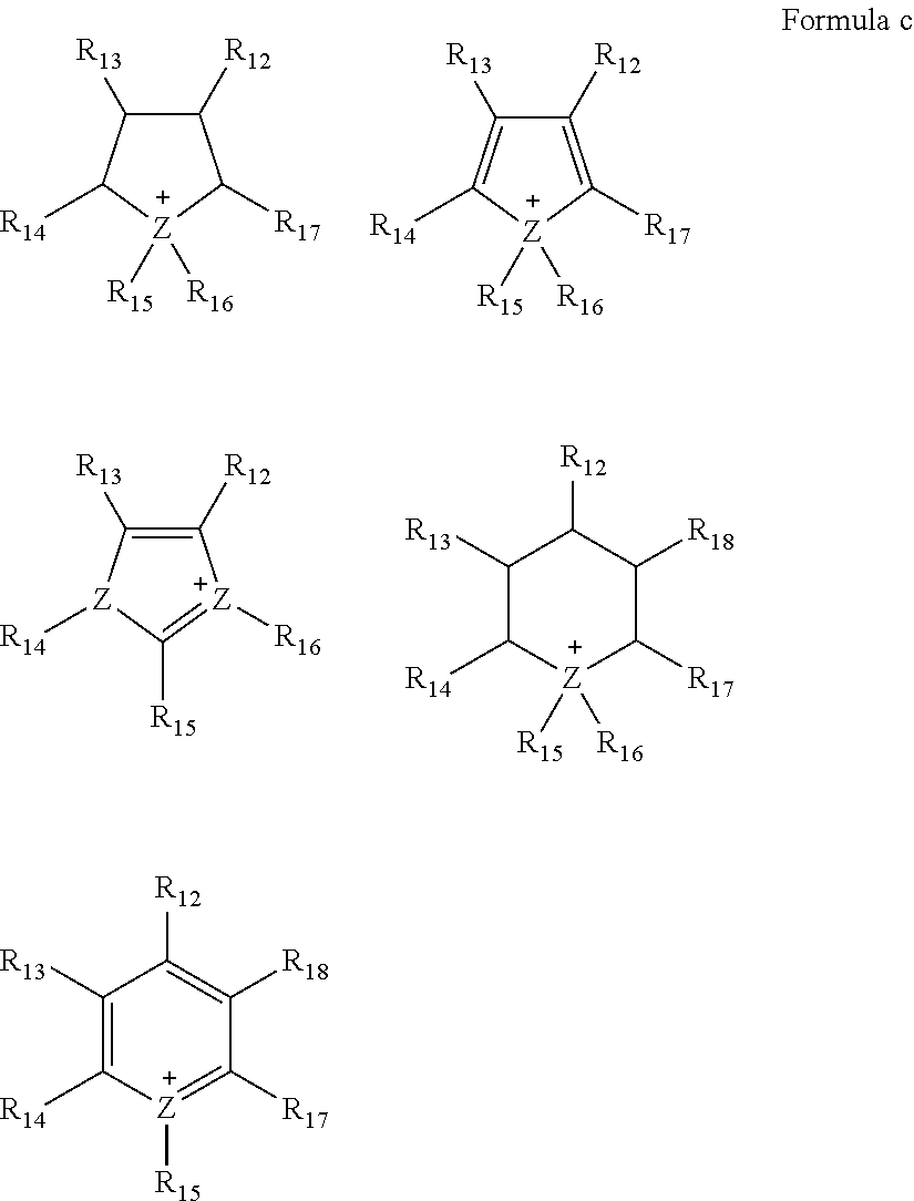
wherein in Formula c, Z is N or P, and each of R12 to R18 is independently hydrogen, a substituted or unsubstituted C1-C30 alkyl group, a substituted or unsubstituted C1-C30 alkoxy group, a substituted or unsubstituted C6-C30 aryl group, a substituted or unsubstituted C6-C30 aryloxy group, a substituted or unsubstituted C3-C30 heteroaryl group, a substituted or unsubstituted C3-C30 heteroaryloxy group, a substituted or unsubstituted C4-C30 cycloalkyl group, a substituted or unsubstituted C3-C30 heterocycloalkyl group, or a substituted or unsubstituted C2-C100 alkyleneoxide group,

wherein in Formula d, Z is N or P, and each of R12 to R15 is independently hydrogen, a substituted or unsubstituted C1-C30 alkyl group, a substituted or unsubstituted C1-C30 alkoxy group, a substituted or unsubstituted C6-C30 aryl group, a substituted or unsubstituted C6-C30 aryloxy group, a substituted or unsubstituted C3-C30 heteroaryl group, a substituted or unsubstituted C3-C30 heteroaryloxy group, a substituted or unsubstituted C4-C30 cycloalkyl group, a substituted or unsubstituted C3-C30 heterocycloalkyl group, or a substituted or unsubstituted C2-C100 alkyleneoxide group.
For example, the ionic liquid may comprise N,N-diethyl-N-methyl-N-(2-methoxyethyl)ammonium tetraborate ([DEME][BF4]), diethyl methyl ammonium trifluoromethane sulfonate ([dema][TfO]), dimethyl propyl ammonium trifluoromethane sulfonate ([dmpa][TfO]), diethyl methyl ammonium trifluoromethane sulfonylimide ([dema][TFSI]), methyl propyl piperidinium trifluoromethane sulfonylimide ([mpp][TFSI]), or a combination thereof. However, the ionic liquid is not limited to the above examples and any suitable organic solvent that is liquid at room temperature may be used.
The lithium salt may comprise lithium bis-trifluoromethanesulfonimide (LiTFSI), LiPF6, LiBF4, LiAsF6, LiClO4, LiNO3, lithium bis(oxalato) borate (LiBOB), LiCF3SO3, LiN(SO2CF3)2, LiN(SO2C2F5)2, LiC(SO2CF3)3, LiN(SO3CF3)2, LiC4F9SO3, LiAlCl4, lithium trifluoromethanesulfonate (LiTfO), or a combination thereof. However, the lithium salt is not limited to the above examples and any suitable lithium salt may be used.
The concentration of the lithium salt may be from about 0.001 molar (M) to about 4.0 M, about 0.01 M to about 2.0 M, or about 0.1 M to about 1.0 M, but is not limited to the above range. When the concentration of the lithium salt is within the range described above, enhanced battery characteristics may be obtained.
The cathode may further include a conductive material. Examples of the conductive material include metallic conductive materials such as metal fibers, metal meshes, and the like. In addition, the metal powder comprising copper, silver, nickel, aluminum, or the like may be used as the metallic conductive material. These metallic conductive materials may be porous. In addition, an organic conductive material such as a polyphenylene derivative and the like may be used. The above-listed conductive materials may be used alone or in combination.
The electrolyte may include a solid electrolyte.
The solid electrolyte may comprise an electrolyte comprising an ionically conducting polymer, a polymeric ionic liquid (PIL), an inorganic electrolyte, a polymer matrix, and an electronically conducting polymer, or a combination thereof. However, the solid electrolyte is not limited to the above examples and any suitable solid electrolyte may be used. The polymer matrix may be ionically and electrically insulating, i.e., may not have ionic conductivity or electronic conductivity.
For example, the solid electrolyte may comprise a polyethylene oxide (PEO), a solid graft copolymer such as a solid graft copolymer comprising containing at least two polymer blocks and having a low glass transition temperature (Tg), poly(diallyldimethylammonium)trifluoromethanesulfonylimide (TFSI), lithium trifluoromethanesulfonate (LiTfO), Cu3N, Li3N, LiPON, Li3PO4.Li2S.SiS2, Li2S. GeS2. Ga2S3, Li2O.11Al2O3, Na2O.11Al2O3, (Na, Li)1+xTi2−xAlx(PO4)3 where 0.1≤x≤0.9, Li1+xHf2−xAlx(PO4)3 where 0.1≤x≤0.9, Na3Zr2Si2PO12, Li3Zr2Si2PO12, Na5ZrP3O12, Na5TiP3O12, Na3Fe2P3O12, Na4NbP3O12, a sodium silicate, Li0.3La0.5TiO3, Na5MSi4O12 wherein M is a rare earth element such as neodymium (Nd), gadolinium (Gd), dysprosium (Dy), or the like, Li5ZrP3O12, Li5TiP3O12, Li3Fe2P3O12, Li4NbP3O12, Li1+x(M, Al, Ga)x(Ge1−yTiy)2−x(PO4)3 where x≤0.8, 0≤y≤1.0, and M is Nd, samarium (Sm), europium (Eu), Gd, terbium (Tb), Dy, holmium (Ho), erbium (Er), thulium (Tm), or ytterbium (Yb), Li1+x+yQxTi2−xSiyP3−yO12 where 0≤x≤0.4, 0≤y≤0.6, and Q is aluminum (Al) or gallium (Ga), Li6BaLa2Ta2O12, Li7La3Zr2O12, Li5La3Nb2O12, Li5La3M2O12 where M is niobium (Nb) or tantalum (Ta), Li7+xAxLa3−xZr2O12 where 0<x<3 and A is zinc (Zn), or a combination thereof.
For example, the solid electrolyte may include, as an ion conductive polymer, an ion conductive repeating unit which may comprise an ether monomer, an acrylate monomer, an acrylic monomer, a methacrylate monomer, a methacrylic monomer, a siloxane monomer, or a combination thereof.
For example, the ion conductive polymer may comprise a polyethylene oxide, a polypropylene oxide, a poly(methyl methacrylate), a poly(ethyl methacrylate), a polydimethylsiloxane, a polyacrylic acid, a polymethacrylic acid, a polymethyl acrylate, a polyethyl acrylate, a poly(2-ethylhexyl acrylate), a poly(butyl methacrylate), a poly(2-ethylhexyl methacrylate), a poly(decyl acrylates), a poly(ethylene vinyl acetate), or a combination thereof.
For example, the ion conductive polymer may be a copolymer comprising an ion conductive repeating unit and a structural repeating unit.
For example, the ion conductive repeating unit may be derived from acrylic acid, methacrylic acid, methyl acrylate, methyl methacrylate, ethyl acrylate, ethyl methacrylate, 2-ethylhexyl acrylate, butyl methacrylate, 2-ethylhexyl methacrylate, decyl acrylate, ethylene vinyl acetate, ethylene oxide, propylene oxide, or a combination thereof. The structural repeating unit may be derived from styrene, 4-bromostyrene, tert-butyl styrene, divinyl benzene, methyl methacrylate, isobutyl methacrylate, butadiene, ethylene, propylene, dimethylsiloxane, isobutylene, N-isopropyl acrylamide, vinylidene fluoride, acrylonitrile, 4-methyl pentene-1, butylene terephthalate, ethylene terephthalate, vinylpyridine, or a combination thereof.
For example, the ion conductive polymer may be a block copolymer including an ion conductive phase and a structural phase. The block copolymer including an ion conductive phase and a structural phase may include, for example, block copolymers as disclosed in U.S. Pat. Nos. 8,269,197 and 8,563,168 and U.S. Patent Publication No. 2011/0206994, the contents of which are incorporated herein by reference in their entirety.
The reaction mechanism of the lithium air battery may be represented by Chemical Equation 1:
4Li+O2 2Li2OE°=2.91 volts (V)
2Li+O2Li2O2E°=3.10 V Chemical Equation 1
4Li+O2
2Li+O2
During battery discharging, lithium derived from the anode reacts with oxygen introduced from the cathode to generate a lithium oxide, and oxygen is reduced (oxygen reduction reaction (ORR)). In contrary, during battery charging, the lithium oxide is reduced, and oxygen is generated by oxidation (oxygen evolution reaction (OER)). Also, during the discharging, Li2O2 is deposited in pores of the cathode, and the capacity of the lithium air battery increases as the area of the electrolyte contacting oxygen in the cathode increases.
The lithium air battery may be manufactured using the following method.
First, an air electrode is prepared as a cathode. For example, the air electrode may be fabricated as follows. An electrode member may be manufactured by mixing the carbonaceous material described above, a solvent, and a lithium salt with or without a suitable solvent to prepare an air electrode slurry, coating the air electrode slurry on a surface of a current collector and drying the coated current collector and, optionally, performing compression molding on the current collector to enhance electrode density. The current collector may be a gas diffusion layer. In another embodiment, the electrode member may be manufactured by coating the air electrode slurry on a surface of a separator or a solid electrolyte membrane and drying the coated member, and optionally compression molding the separator or the solid electrolyte membrane to enhance electrode density.
The carbonaceous material, the solvent, and the lithium salt used in the air electrode slurry have already been described above and thus further detailed description thereof will not be repeated for clarity.
The air electrode slurry may optionally include a binder in addition to the binder described above.
To rapidly diffuse oxygen, the current collector may be a porous structure in a net or mesh form or a porous metal plate formed of stainless steel, nickel, aluminum, or the like. However, the current collector is not limited to the above examples, and any suitable current collector may be used. The current collector may be coated with an oxidation resistant metal or alloy in order to prevent oxidation of the current collector.
The air electrode slurry may selectively include a catalyst for oxidation/reduction of oxygen and a conductive material. In addition, the air electrode slurry may optionally include lithium oxide.
A catalyst for oxidation/reduction of oxygen may be added to the cathode. Examples of the catalyst include a precious metal catalyst such as platinum, gold, silver, palladium, ruthenium, rhodium, osmium, or a combination thereof; an oxide catalyst such as manganese oxide, iron oxide, cobalt oxide, nickel oxide, or a combination thereof; or an organic metal catalyst such as cobalt phthalocyanine. A combination comprising at least one of the foregoing may be used. However, the catalyst is not particularly limited to the above examples and any suitable catalyst for oxidation/reduction of oxygen may be used.
In addition, the catalyst may be supported on a catalyst support. The catalyst support may comprise an oxide, a zeolite, a clay-based mineral, carbon, or the like. The oxide may comprise alumina, silica, zirconium oxide, titanium dioxide, or a combination thereof. The oxide may comprise an oxide comprising metal, and the metal may comprise cerium (Ce), praseodymium (Pr), samarium (Sm), Eu, Tb, Tm, Yb, antimony (Sb), bismuth (Bi), vanadium (V), chromium (Cr), manganese (Mn), iron (Fe), cobalt (Co), nickel (Ni), copper (Cu), Nb, molybdenum (Mo), tungsten (W), or a combination thereof. Examples of the carbon include a carbon black such as Ketjen black, acetylene black, channel black, lamp black, or a combination thereof; a graphite such as natural graphite, artificial graphite, expandable graphite, or a combination thereof; an activated carbon; or carbon fiber. A combination comprising at least one of the foregoing may be used. However, the carbon is not limited to the above examples and any suitable catalyst support may be used.
Next, an anode is prepared.
The anode may be, for example, a lithium metal thin film. A lithium metal alloy may be, for example, an alloy of lithium with aluminum, tin, magnesium, indium, calcium, titanium, vanadium, or a combination thereof.
In addition, a separator may be disposed between the cathode and the anode. The separator is not particularly limited as long as it has a composition that can withstand service conditions of the lithium air battery. Examples of the separator include a polymer nonwoven fabric such as a polypropylene nonwoven fabric or a polyphenylene sulfide nonwoven fabric; a porous film comprising an olefin resin such as polyethylene or polypropylene. A combination comprising at least one of these materials may be used.
An oxygen-blocking film that is impervious to oxygen may be disposed between the cathode and the anode. The oxygen-blocking film may be a lithium ion conductive solid electrolyte membrane and serve as a protective film that prevents impurities such as oxygen and the like included in the electrolyte at the cathode from directly reacting with a Li metal anode. A material for forming the lithium ion conductive solid electrolyte membrane impervious to oxygen may be a lithium ion conductive glass, a lithium ion conductive crystal (e.g., a ceramic or glass-ceramic), or an inorganic material containing a mixture thereof. However, the material is not particularly limited to the above examples and any suitable solid electrolyte membrane that has lithium ion conductivity, is impervious to oxygen, and protects an anode may be used. Taking chemical stability of the lithium ion conductive solid electrolyte membrane into consideration, the lithium ion conductive solid electrolyte membrane may include an oxide.
The lithium ion conductive solid electrolyte membrane has a high ionic conductivity when including a large amount of lithium ion conductive crystals and thus the amount of the lithium ion conductive crystals may be, for example, about 50 weight percent (wt %) or more, for example, about 55 wt % or more, or about 60 wt % or more, with respect to the total weight of the lithium ion conductive solid electrolyte membrane. The amount of the lithium ion conductive crystals may be about 50 wt % to about 95 wt %, about 60 wt % to about 90 wt %, or about 70 wt % to about 90 wt %, with respect to the total weight of the lithium ion conductive solid electrolyte membrane.
Examples of the lithium ion conductive crystals include perovskite crystals with lithium ion conductivity, such as Li3N, LISICONs, and La0.55Li0.35TiO3, LiTi2P3O12 crystals having a NASICON structure, and glass-ceramic that deposits these crystals.
For example, the lithium ion conductive crystal may be Li1+x+y(Al, Ga)x(Ti, Ge)2−xSiyP3−yO12 where 0≤x≤1 and 0≤y≤1, for example, 0≤x≤0.4 and 0<y≤0.6, or 0.1≤x≤0.3 and 0.1<y≤0.4. To have a high ionic conductivity, the lithium ion conductive crystal desirably does not have grain boundaries that inhibit ionic conductivity. For example, a glass-ceramic may contain few pores or grain boundaries that inhibit ionic conductivity and thus may have high ionic conductivity and chemical stability.
Non-limiting examples of the lithium ion conductive glass-ceramic include lithium-aluminum-germanium-phosphate (LAGP), lithium-aluminum-titanium-phosphate (LATP), and lithium-aluminum-titanium-silicon-phosphate (LATSP).
For example, when a parent glass having a composition of Li2O—Al2O3—TiO2—SiO2—P2O5 is crystallized by heat treatment, a primary crystal phase of the parent glass comprise, e.g., consist of, Li1+x+yAlxTi2−xSiyP3−yO12 where 0≤x≤1 and 0≤y≤1. In this regard, x and y may satisfy the conditions: 0≤x≤0.4 and 0≤y≤0.6, or 0.1≤x≤0.3 and 0.1≤y≤0.4.
The term “pores or grain boundaries that inhibit ionic conductivity” used herein refers to ionic conductivity-inhibiting materials, such as pores or grain boundaries that reduce the lithium ion conductivity of an inorganic material including lithium ion conductive crystals to a tenth or less that of the lithium ion conductive crystals in the inorganic material.
For example, the oxygen blocking film may comprise Li1+x+yAlxTi2−xSiyP3−yO12 where 0≤x≤1 and 0≤y≤1. In this regard, x and y satisfy, for example, the conditions: 0≤x≤0.4 and 0<y≤0.6, or 0.1≤x≤0.3 and 0.1<y≤0.4.
For example, the oxygen blocking film may comprise Li1+x+yAlx(Ti, Ge)2−xSiyP3−yO1 where 0≤x≤2 and 0≤y≤3 and may comprise, for example, a solid electrolyte membrane including Li1.4Ti1.6Al0.4P3O12 (LATP).
The lithium air battery may further include an anode interlayer between the anode and the oxygen-blocking film. The anode interlayer may be employed to prevent a side reaction generated between the anode and the oxygen-blocking film.
The anode interlayer may include a solid polymer electrolyte. For example, the solid polymer electrolyte may comprise a lithium salt-doped polyethylene oxide (PEO) and non-limiting examples of the lithium salt include LiN(SO2CF2CF3)2, LiBF4, LiPF6, LiSbF6, LiAsF6, LiClO4, LiCF3SO3, LiN(SO2CF3)2, LiN(SO2C2F5)2, LiC(SO2CF3)3, LiN(SO3CF3)2, LiC4F9SO3, and LiAlCl4.
The lithium air battery may be a lithium primary battery or a lithium secondary battery. In addition, the lithium air battery may have, for example, a coin shape, a button shape, a sheet shape, a stack shape, a cylinder shape, a panel shape, a corn shape, or the like, but the shape is not limited thereto. Also, the lithium air battery may be used as a large-size battery for electric vehicles and the like.
The term “air” used herein is not limited to atmospheric air, and refers to either a gas combination including oxygen or a pure oxygen gas. The broad definition of the term “air” may be applied to all kinds of applications including an air battery, an air cathode, and the like.
The lithium air battery has improved thermal stability and improved high temperature charge/discharge characteristics and may be used in electric vehicles (EVs). In addition, the lithium air battery may be used in hybrid vehicles such as plug-in hybrid electric vehicles (PHEVs) and the like.
In addition, the term “substituted” as used herein means substitution with a halogen atom, a C1-C20 alkyl group substituted with a halogen atom (e.g., —CCF3, —CHCF2, —CH2F, —CCl3, or the like), a hydroxyl group, a nitro group, a cyano group, an amino group, an amidino group, a hydrazine, a hydrazone, a carboxyl group or a salt thereof, a sulfonic acid or a salt thereof, a phosphoric acid or a salt thereof, a C1-C20 alkyl group, a C2-C20 alkenyl group, a C2-C20 alkynyl group, a C1-C20 heteroalkyl group, a C6-C20 aryl group, a C6-C20 arylalkyl group, a C6-C20 heteroaryl group, or a C6-C20 heteroarylalkyl group.
“Alkyl” as used herein means a straight or branched chain, saturated, monovalent hydrocarbon group (e.g., methyl or hexyl).
“Aryl” means a monovalent group formed by the removal of one hydrogen atom from one or more rings of an arene (e.g., phenyl or napthyl). alkenyl
“Cycloalkyl” means a monovalent group having one or more saturated rings in which all ring members are carbon (e.g., cyclopentyl and cyclohexyl).
“Alkylene oxide” means an aliphatic C2 to C100 epoxide, for example ethylene oxide, propylene oxide or butylene oxide. “Aryloxy” means an aryl moiety that is linked via an oxygen (i.e., —O-aryl). An aryloxy group includes a C6 to C30 aryloxy group, and specifically a C6 to C18 aryloxy group. Non-limiting examples include phenoxy, naphthyloxy, and tetrahydronaphthyloxy.
The prefix “hetero” means that the compound or group includes at least one a heteroatom (e.g., 1, 2, or 3 heteroatom(s)), wherein the heteroatom(s) is each independently N, O, S, Si, or P.
A method of manufacturing the cathode for a lithium air battery, according to another embodiment, may include: obtaining a mixture of a polysilsesquioxane precursor and a first solvent; drying the mixture of the polysilsesquioxane precursor and the first solvent to obtain an amorphous polysilsesquioxane ionic liquid; adding a carbonaceous core and a second solvent to the amorphous polysilsesquioxane ionic liquid to provide a solution; drying the solution to manufacture a carbonaceous material comprising a carbonaceous core, and a coating layer on the carbonaceous core, wherein the coating layer comprises an amorphous polysilsesquioxane ionic liquid having a viscosity of at least 0.2 milliPascal-seconds as measured in an aprotic solvent, for example as a 10 weight percent solution in acetone, at 30° C.; and disposing the carbonaceous material and a binder on a substrate to manufacture the cathode.
The obtaining of the amorphous polysilsesquioxane ionic liquid may include obtaining amorphous polysilsesquioxane ionic liquid by hydrolysis-condensation of the polysilsesquioxane precursor in the first solvent.
In the obtaining of the amorphous polysilsesquioxane ionic liquid, amorphous polysilsesquioxane ionic liquid may be obtained by two reactions: hydrolysis and condensation. In the hydrolysis process, a polysilsesquioxane precursor as a starting material is hydrolyzed to form a silanol as a reaction intermediate and the silanol, which has a strong hydrogen bond, is self-assembled to a ladder-type structure to form an aggregate, and the condensation reaction is performed by introducing an anion.
The polysilsesquioxane precursor may include 3-(trimethoxysilyl)propyl-N,N,N-trimethylammonium chloride, and at least one compound selected from N,N-bis(trifluoromethanesulfonyl)imide, N,N-bis(trifluoroethanesulfonyl)imide, and a compound represented by Formula 1-2:

wherein x1 may be an integer from 3 to 5;
y1 may be an integer from 100 to 1000; and
m1 may be an integer of 1 or more.
As the polysilsesquioxane precursor, 3-(trimethoxysilyl)propyl-N,N,N-trimethylammonium chloride may be hydrolyzed more easily than a (trialkoxysilyl)propyl compound having other carbon numbers. In addition, N,N-bis(trifluoromethanesulfonyl)imide, N, N-bis(trifluoroethanesulfonyl)imide, or the compound of Formula 1-2 may serve as an appropriate plasticizer in the formation of a coating layer.
Thus, the amorphous polysilsesquioxane ionic liquid obtained from the polysilsesquioxane precursor may enable formation of a coating layer that is amorphous and has a high viscosity. A lithium air battery including such coating layer may have enhanced thermal stability and improved high temperature charge/discharge characteristics.
The mixture of a polysilsesquioxane precursor and a first solvent may have a gel phase at 60° C.
The first solvent may include a mixed solvent of methanol and water. A volume ratio of the mixed solvent may be from about 2:1 to about 6:1. For example, the volume ratio of the mixed solvent may be from about 3:1 to about 5:1, for example, from about 3.9:1 to about 4.1:1. The mixed solvent having the volume ratio within the ranges described above is understood to participate in the condensation reaction and consequently, ladder-type amorphous polysilsesquioxane ionic liquid having a high viscosity may be obtained.
Next, a carbonaceous core and a second solvent are added to the amorphous polysilsesquioxane ionic liquid to provide a solution, and the resulting solution is dried, thereby completing the preparation of the carbonaceous material described above. The carbonaceous core has already been described and thus further description thereof will not be repeated for clarity. The second solvent may be the organic solvent described above, ionic liquid, or the like and a detailed description thereof will be omitted herein.
The cathode material described above is added to the carbonaceous material, thereby completing the manufacture of the cathode for a lithium air battery.
An embodiment will now be disclosed in further detail with reference to the following examples and comparative examples. These examples are for illustrative purposes only and are not intended to limit the scope of the disclosed embodiment.
4.2 grams (g) of N,N-bis(trifluoromethanesulfonyl)imide (TFSI, from Sigma Aldrich) as a precursor was added to a methanol solution in which 7.72 g of 3-(trimethoxysilyl)propyl-N,N,N-trimethylammonium chloride was dissolved and 30 g of deionized water and the resulting solution was stirred for two hours to prepare a mixture. The mixture was dispersed using a centrifugal separator at 5000 revolutions per minute (rpm) for 5 minutes and 30 g of deionized water was further added thereto to obtain a dispersion. This process was repeated 10 times.
The dispersion was vacuum-dispersed at 20° C. for 2 hours, 3 g of methanol was added thereto, and the resulting dispersion was mixed for 10 minutes, followed by further drying at 60° C. for 12 hours and at 150° C. for 12 hours, thereby obtaining amorphous polysilsesquioxane ionic liquid.
Amorphous polysilsesquioxane ionic liquid was prepared in the same manner as in Preparation Example 1, except that 5.69 g of N,N-bis(pentafluoroethanesulfonyl)imide (BETI, from Apollo Scientific Ltd) was added instead of adding 4.2 g of N,N-bis(trifluoromethanesulfonyl)imide (TFSI, from Sigma Aldrich).
Amorphous polysilsesquioxane ionic liquid was prepared in the same manner as in Preparation Example 1, except that 25 g (20 wt %) of Nafion perfluorosulfonic acid (DE-2021, from Dupont), prepared by dissolving a compound represented by Formula 1-2 in a lower aliphatic alcohol and water, was added instead of adding 4.2 g of N,N-bis(trifluoromethanesulfonyl)imide (TFSI, from Sigma Aldrich).

wherein x1 is an integer from 3 to 5;
y1 is an integer from 100 to 1000; and
m1 is an integer of 1 or 2.
0.09 g of multi-walled carbon nanotubes (from XinNano Materials Inc., Taiwan, D: 8 nm, L: 10 μm) and 0.01 g of the amorphous polysilsesquioxane ionic liquid prepared according to Preparation Example 1 were added to 10 g of acetone and the resulting solution was stirred for 2 hours to prepare a mixture. The mixture was filtered and then the filtrate was dried at 60° C. for 12 hours, followed by further drying in vacuum at 120° C. for 1 hour to obtain a carbonaceous material in which a coating layer formed of the amorphous polysilsesquioxane ionic liquid was formed on a core formed of the multi-walled carbon nanotubes.
A carbonaceous material was prepared in the same manner as in Preparation Example 4, except that 0.01 g of the amorphous polysilsesquioxane ionic liquid prepared according to Preparation Example 2 was added instead of 0.01 g of the amorphous polysilsesquioxane ionic liquid of Preparation Example 1.
A carbonaceous material was prepared in the same manner as in Preparation Example 4, except that 0.01 g of the amorphous polysilsesquioxane ionic liquid prepared according to Preparation Example 3 was added instead of 0.01 g of the amorphous polysilsesquioxane ionic liquid of Preparation Example 1.
Multi-walled carbon nanotubes (from XinNano Materials Inc., D: 8 nm, L: 10 μm) were prepared as a carbonaceous material.
1 Milligram (mg) of the carbonaceous material prepared according to Preparation Example 4, 0.3 molar (M) lithium bis(trifluoromethane sulfonyl)imide (LiTFSI) as a lithium salt, and 2 mg of diethylmethylammonium bis(trifluoromethane sulfonyl)imide (DEMA-TFSI) were mixed in a mortar for about 5 minutes to prepare a cathode paste.
The cathode paste was spread on a solid electrolyte membrane (LICGC™ (LATP, from Ohara, thickness: 250 micrometers (μm))) and then coated thereon using a roller to manufacture a cathode/solid electrolyte membrane structure. In this regard, the cathode had a loading amount of 3.0 milligrams per square centimeter (mg/cm2).
A cathode/solid electrolyte membrane structure was manufactured in the same manner as in Example 1, except that 0.5M LiTFSI was added as a lithium salt to prepare a cathode paste, instead of 0.3 M LiTFSI. In this regard, the cathode had a loading amount of 3.0 mg/cm2.
A cathode/solid electrolyte membrane structure was manufactured in the same manner as in Example 1, except that 2 mg of the carbonaceous material prepared according to Preparation Example 5 was used instead of 1 mg of the carbonaceous material of Preparation Example 4. In this regard, the cathode had a loading amount of 3.0 mg/cm2.
A cathode/solid electrolyte membrane structure was manufactured in the same manner as in Example 1, except that 2 mg of the carbonaceous material prepared according to Preparation Example 6 was used instead of 1 mg of the carbonaceous material of Preparation Example 4. In this regard, the cathode had a loading amount of 3.0 mg/cm2.
A cathode/solid electrolyte membrane structure was manufactured in the same manner as in Example 1, except that 2 mg of the carbonaceous material prepared according to Comparative Preparation Example 1 was used instead of 1 mg of the carbonaceous material of Preparation Example 4. In this regard, the cathode had a loading amount of 3.0 mg/cm2.
A cathode/solid electrolyte membrane structure was manufactured in the same manner as in Example 2, except that 2 mg of the carbonaceous material of Comparative Preparation Example 1 was used instead of 1 mg of the carbonaceous material of Preparation Example 4. In this regard, the cathode had a loading amount of 3.0 mg/cm2.
0.3 M LiTFSI as a lithium salt and 2 mg of trimethylpropylammonium were mixed in a mortar for about 5 minutes to prepare a cathode paste.
The cathode paste was spread on a solid electrolyte membrane (LICGC™ (LATP, from Ohara, thickness: 250 μm)) and then coated thereon using a roller to manufacture a cathode/solid electrolyte membrane structure. In this regard, the cathode had a loading amount of 3.0 mg/cm2.
A stainless steel wire (SUS) mesh 12 was fixed on a Teflon case, a lithium metal anode 13 having a diameter of 16 millimeters (mm) was mounted thereon, and then a PEO film (thickness: 150 μm) was used as an anode interlayer (not shown) on the lithium metal anode 13 to prevent direct contact between LATP and Li. In this regard, the PEO film was prepared according to the following processes.
Polyethylene oxide having a weight average molecular weight (Mw) of 600,000 Daltons and LiTFSI were added to 100 milliliters (mL) of acetonitrile and mixed therein for at least 12 hours. A mixing ratio of LiTFSI and polyethylene oxide was 1:18 on a molar basis.
The lithium metal anode 13 and the anode interlayer were stacked and the cathode/solid electrolyte membrane structure manufactured according to Example 1 was mounted thereon to manufacture a cell having a structure as illustrated in FIG. 1 . As illustrated in FIG. 1 , an LATP solid electrolyte membrane 16 (thickness: 250 μm) as an oxygen-blocking film was disposed so as to contact the anode interlayer (not shown).
Finally, the lithium air battery was covered with a Teflon case and fixed by a pressing member.
A lithium air battery was manufactured in the same manner as in Example 5, except that the cathode/solid electrolyte membrane structure manufactured according to Example 2 was used instead of the cathode/solid electrolyte membrane structure of Example 1.
A lithium air battery was manufactured in the same manner as in Example 5, except that the cathode/solid electrolyte membrane structure manufactured according to Example 3 was used instead of the cathode/solid electrolyte membrane structure of Example 1.
A lithium air battery was manufactured in the same manner as in Example 5, except that the cathode/solid electrolyte membrane structure manufactured according to Example 4 was used instead of the cathode/solid electrolyte membrane structure of Example 1.
A lithium air battery was manufactured in the same manner as in Example 5, except that the cathode/solid electrolyte membrane structure manufactured according to Comparative Example 1 was used instead of the cathode/solid electrolyte membrane structure of Example 1.
A lithium air battery was manufactured in the same manner as in Example 5, except that the cathode/solid electrolyte membrane structure manufactured according to Comparative Example 2 was used instead of the cathode/solid electrolyte membrane structure of Example 1.
A lithium air battery was manufactured in the same manner as in Example 5, except that the cathode/solid electrolyte membrane structure manufactured according to Comparative Example 3 was used instead of the cathode/solid electrolyte membrane structure of Example 1.
10 mg of the amorphous polysilsesquioxane ionic liquid of Preparation Example 1 was dissolved in 0.5 mL of a mixed solvent of CDCl2 and acetone in a volume ratio of 1:2 and 1H NMR spectrum analysis and 29Si NMR spectrum analysis of the resulting solution were conducted. The analysis results are shown in FIGS. 2 and 3 .
The 1H NMR analysis was implemented using Unity NOVA600 (from Varian, 600 MHz). The 29Si NMR spectrum analysis was implemented using AVANCEIII (from Bruker, 600 MHz).
Referring to FIG. 2 , in the 1H NMR spectrum analysis, 4 peaks (a, b, c and d portions) derived from 3-(trimethylammonium)propyl of the amorphous polysilsesquioxane ionic liquid of Preparation Example 1 are observed.
Referring to FIG. 3 , in the 29Si NMR spectrum analysis, two wide peaks are observed at −57 and −70 ppm versus TMS. This result indicates that 3-(trimethoxysilyl)propyl-N,N,N-trimethylammonium chloride and N,N-bis(trifluoromethanesulfonyl)imide as precursors of the amorphous polysilsesquioxane ionic liquid of Preparation Example 1 form a siloxane bond as a main chain through hydrolysis and condensation.
XRD analysis was performed on the amorphous polysilsesquioxane ionic liquid of Preparation Example 1. The analysis results are illustrated in FIG. 4 .
Referring to FIG. 4 , the amorphous polysilsesquioxane ionic liquid of Preparation Example 1 has two wide and smooth peaks. From the results shown in FIG. 4 , it is confirmed that the amorphous polysilsesquioxane ionic liquid of Preparation Example 1 had an amorphous-like structure.
MALDI-TOF mass spectrometry was performed on the amorphous polysilsesquioxane ionic liquid of Preparation Example 1. The analysis results are illustrated in FIG. 5 .
The MALDI-TOF mass spectrometry was performed using an MALDI-TOF mass spectrometer from PerSeptive Biosystems, Framingham (337 nm nitrogen laser, accelerating voltage of 20 kV, 1.2 m flight tube, average signal: 20). For calibration, a polymer standard having a number average molecular weight Mn of 470 Daltons was used.
A sample for the MALDI-TOF mass spectrometry was prepared by dissolving 10 mg of the amorphous polysilsesquioxane ionic liquid of Preparation Example 1 in 1 mL of tetrahydrofuran and applying the resulting solution on a graphite plate. Dithranol was prepared as a matrix.
Referring to FIG. 5 , it is confirmed that the amorphous polysilsesquioxane ionic liquid of Preparation Example 1 had a weight average molecular weight (Mw) of about 2,780 Daltons.
The phase of the amorphous polysilsesquioxane ionic liquid of Preparation Example 1 at 60° C. was evaluated using the following method. The evaluation results are shown in FIG. 6 .
To observe the phase of the amorphous polysilsesquioxane ionic liquid, the mixture prepared in Preparation Example 1 was added in an amount of about ½ the total volume of a beaker, heat-treated at 100° C. for 1 hour in an air atmosphere, and then cooled down to 60° C. at room temperature.
Referring to FIG. 6 , the amorphous polysilsesquioxane ionic liquid has a gel phase at 60° C.
A TGA experiment was carried out on the carbonaceous material and the ionic liquid respectively included in the cathodes for a lithium air battery of Example 1 and Comparative Example 3 at a heating rate of 5° C./min each in a nitrogen atmosphere and in air. The results are illustrated in FIGS. 7A and 7B .
In the TGA experiment, TA(SDT: TGA+DSC) 2010 TGA/DSC1 (from METTLER TOLEDO) (temperature range: 0° C. to 700° C.) was used.
5 weight percent (wt %) loss temperatures Td of the carbonaceous material and the ionic liquid are shown in Table 1.
| TABLE 1 | |||
| Nitrogen atmosphere, Td (° C.) | Air, Td (° C.) | ||
| Example 1 | 413 | 401 |
| Comparative | 380 | 370 |
| Example 3 | ||
Referring to FIGS. 7A and 7B and Table 1, the carbonaceous material included in the cathode for a lithium air battery of Example 1 had 5 wt % greater weight loss than the ionic liquid included in the cathode for a lithium air battery of Comparative Example 3 in a nitrogen atmosphere and also in air.
From the results above, it is confirmed that the carbonaceous material included in the cathode of Example 1 has higher thermal stability than the ionic liquid included in the cathode of Comparative Example 3.
Charge/discharge characteristics experiment was performed such that each of the lithium air batteries of Examples 5 and 6 and Comparative Examples 4 and 5 was discharged at a constant current of 0.24 mA/cm2 at 60° C. and 1 atmosphere (atm) in an oxygen atmosphere until the voltage reached 1.8 V (vs. Li), charged at the same constant current up to 4.15 V, and then charged at a constant voltage until the current reached 0.02 mA/cm2.
To evaluate the charge/discharge characteristics, a charger/discharger (TOSCAT, series 3100, Japan) was used.
A Coulombic efficiency is defined by Equation 1 and calculated using TOSCAT Series Data Plot Program, Ver. 8.3.24 software. Cyclability is defined as the number of cycles.
A part (Coulombic efficiency at 30th cycle) of the results is shown in Table 2 and FIG. 8 .
Coulombic efficiency (%)=[(discharge capacity at each cycle/charge capacity at each cycle)]×100% Equation 1
Coulombic efficiency (%)=[(discharge capacity at each cycle/charge capacity at each cycle)]×100
In Equation 1, a unit weight at discharge capacity and charge capacity denotes the weight of a cathode including a carbonaceous material, a lithium salt, and an electrolyte.
| TABLE 2 | |||
| Coulombic efficiency at | |
||
| 30th cycle (%) | (number of cycles) | ||
| Example 5 | 101.4 | 54 | ||
| Example 6 | 101.7 | 55 | ||
| Comparative | 103.1 | 39 | ||
| Example 4 | ||||
| Comparative | 103.1 | 34 | ||
| Example 5 | ||||
Referring to FIG. 8 and Table 2, it is confirmed that the lithium air batteries of Examples 5 and 6 have enhanced Coulombic efficiency at 60° C., i.e., nearly 100.0%, as compared to the lithium air batteries of Comparative Examples 4 and 5.
In addition, it is confirmed that the lithium air batteries of Examples 5 and 6 have enhanced cyclability at 60° C. as compared to the lithium air batteries of Comparative Examples 4 and 5.
As is apparent from the foregoing description, a cathode includes a carbonaceous material including, on a carbonaceous core, a coating layer including amorphous polysilsesquioxane ionic liquid having a viscosity (n) of at least 0.2 mPa·s in an aprotic solvent at 30° C. and thus a lithium air battery including the cathode may have enhanced thermal stability and charge/discharge characteristics at high temperatures.
It should be understood that embodiments described herein should be considered in a descriptive sense only and not for purposes of limitation. Descriptions of features or aspects within each embodiment should be considered as available for other similar features or aspects in other embodiments.
While an embodiment has been described with reference to the figures, it will be understood by those of ordinary skill in the art that various changes in form and details may be made therein without departing from the spirit and scope as defined by the following claims.
Claims (20)
1. A cathode for a lithium air battery comprising a carbonaceous material, the carbonaceous material comprising:
a carbonaceous core; and
a coating layer on the carbonaceous core,
wherein the coating layer comprises an amorphous polysilsesquioxane ionic liquid, wherein the amorphous polysilsesquioxane ionic liquid has a viscosity of at least 0.2 milliPascal-seconds as measured as a 10 weight percent solution in acetone at 30° C.
2. The cathode of claim 1 , wherein the amorphous polysilsesquioxane ionic liquid has a viscosity of about 0.2 milliPascal-seconds to about 1200 milliPascal-seconds as measured as a 10 weight percent solution in acetone at 30° C.
3. The cathode of claim 1 , wherein the amorphous polysilsesquioxane ionic liquid is a ladder type amorphous polysilsesquioxane ionic liquid.
4. The cathode of claim 1 , wherein the amorphous polysilsesquioxane ionic liquid is represented by Formula 1:

wherein n is an integer from 1 to 20,
each of R1 to R7 is independently hydrogen, a hydroxyl group, a substituted or unsubstituted organic functional group, a substituted or unsubstituted silicon functional group, or a combination thereof,
X+ is a quaternary nitrogen-containing cation functional group,
Y− is (CF3SO2)2N−, (C2F5SO2)2N−, CF3SO3 −, an anion represented by Formula 1-1, or a combination thereof,

wherein x is an integer from 0 to 15,
y is an integer from 0 to 1000, and
m is an integer of 1 or more.
5. The cathode of claim 4 , wherein, in Formula 1, the quaternary nitrogen-containing cation functional group comprises a quaternary nitrogen-containing cation of Formulas 2A to 2F, or a combination thereof:

wherein each R′ is independently a hydrogen atom, a hydroxyl group, a substituted or unsubstituted C1-C20 alkyl group, a substituted or unsubstituted C6-C20 aryl group, a substituted or unsubstituted C2-C20 alkenyl group, a substituted or unsubstituted C3-C10 cycloalkyl group, a substituted or unsubstituted C1-C20 alkyleneoxide group, a substituted or unsubstituted acrylate group, a substituted or unsubstituted methacrylate group, or a combination thereof.
6. The cathode of claim 4 , wherein, in Formula 1, each of R1 to R7 is independently a hydrogen atom, a hydroxyl group, a substituted or unsubstituted C1-C20 alkyl group, a substituted or unsubstituted C2-C20 alkenyl group, a substituted or unsubstituted C3-C20 cycloalkyl group, a substituted or unsubstituted C6-C20 aryl group, a substituted or unsubstituted C1-C20 alkyleneoxide group, a substituted or unsubstituted acrylate group, a substituted or unsubstituted methacrylate group, or a combination thereof.
7. The cathode of claim 1 , wherein the amorphous polysilsesquioxane ionic liquid is represented by Formula 3:

wherein n1 is an integer from 1 to 20,
each of R″1 to R″7 is independently a hydrogen atom, a hydroxyl group, a substituted or unsubstituted C1-C20 alkyl group, a substituted or unsubstituted C2-C20 alkenyl group, a substituted or unsubstituted C3-C20 cycloalkyl group, a substituted or unsubstituted C6-C20 aryl group, a substituted or unsubstituted C1-C20 alkyleneoxide group, a substituted or unsubstituted acrylate group, a substituted or unsubstituted methacrylate group, or a combination thereof, and
Y1 − is (CF3SO2)2N−, (C2F5SO2)2N−, CF3SO3, the anion of Formula 1-1, or a combination thereof,

wherein x is an integer from 0 to 15,
y is an integer from 0 to 1000, and
m is an integer of 1 or more.
8. The cathode of claim 1 , wherein the amorphous polysilsesquioxane ionic liquid has a weight average molecular weight of greater than about 1,800 Daltons to about 5,000 Daltons.
9. The cathode of claim 1 , wherein the amorphous polysilsesquioxane ionic liquid has a gel phase at 60° C.
10. The cathode of claim 1 , wherein an amount of the coating layer is from about 1 weight percent to about 30 weight percent, based on a total weight of the cathode.
11. The cathode of claim 1 , wherein the coating layer is in a form of a continuous coating or an island coating.
12. The cathode of claim 1 , wherein the carbonaceous core comprises carbon nanotubes.
13. The cathode of claim 1 , wherein the carbonaceous core comprises porous multi-walled carbon nanotubes.
14. The cathode of claim 1 , further comprising a binder.
15. A lithium air battery comprising:
the cathode according to claim 1 ;
an anode capable of intercalating and deintercalating lithium; and
an electrolyte disposed between the cathode and the anode.
16. A method of manufacturing a cathode for a lithium air battery, the method comprising:
obtaining a mixture of a polysilsesquioxane precursor and a first solvent;
drying the mixture of the polysilsesquioxane precursor and the first solvent to obtain an amorphous polysilsesquioxane ionic liquid;
adding a carbonaceous core and a second solvent to the amorphous polysilsesquioxane ionic liquid to provide a solution;
drying the solution to manufacture a carbonaceous material comprising
a carbonaceous core, and
a coating layer on the carbonaceous core, wherein the coating layer comprises an amorphous polysilsesquioxane ionic liquid having a viscosity of at least 0.2 milliPascal-seconds as measured as a 10 weight percent solution in acetone at 30° C.; and
disposing the carbonaceous material and a binder on a substrate to manufacture the cathode.
17. The method of claim 16 , wherein the obtaining comprises hydrolyzing and condensing the polysilsesquioxane precursor in the first solvent to obtain the amorphous polysilsesquioxane ionic liquid.
18. The method of claim 16 , wherein the polysilsesquioxane precursor comprises 3-(trimethoxysilyl)propyl-N,N,N-trimethylammonium chloride, and N,N-bis(trifluoromethanesulfonyl)imide, N,N-bis(trifluoroethanesulfonyl)imide, a compound represented by Formula 1-2, or a combination thereof:

wherein x1 is an integer from 3 to 5,
y1 is an integer from 100 to 1000, and
m1 is an integer of 1 or more.
19. The method of claim 16 , wherein the first solvent comprises methanol and water.
20. The method of claim 19 , wherein a volume ratio of the methanol to the water is about 2:1 to about 6:1.
Applications Claiming Priority (2)
| Application Number | Priority Date | Filing Date | Title |
|---|---|---|---|
| KR10-2015-0167505 | 2015-11-27 | ||
| KR1020150167505A KR20170062095A (en) | 2015-11-27 | 2015-11-27 | Cathode for lithium air battery, lithium air battery including the same, and method of preparing the cathode for lithium air battery |
Publications (2)
| Publication Number | Publication Date |
|---|---|
| US20170155178A1 US20170155178A1 (en) | 2017-06-01 |
| US10199701B2 true US10199701B2 (en) | 2019-02-05 |
Family
ID=58777831
Family Applications (1)
| Application Number | Title | Priority Date | Filing Date |
|---|---|---|---|
| US15/161,538 Active 2037-07-27 US10199701B2 (en) | 2015-11-27 | 2016-05-23 | Cathode for lithium air batter, lithium air battery including the same, and method of manufacturing cathode for lithium air battery |
Country Status (2)
| Country | Link |
|---|---|
| US (1) | US10199701B2 (en) |
| KR (1) | KR20170062095A (en) |
Families Citing this family (3)
| Publication number | Priority date | Publication date | Assignee | Title |
|---|---|---|---|---|
| KR102466675B1 (en) * | 2017-08-25 | 2022-11-14 | 삼성전자주식회사 | Carbon composite, Electrode and Lithium air battery comprising carbon composite, and Preparation method of carbon composite |
| CN111180746B (en) * | 2019-12-31 | 2022-11-29 | 蔚蓝(广东)新能源科技有限公司 | Metal-air electrode |
| CN112687855B (en) * | 2020-12-22 | 2022-08-09 | 安普瑞斯(南京)有限公司 | Positive electrode material, preparation method thereof, electrode and battery |
Citations (12)
| Publication number | Priority date | Publication date | Assignee | Title |
|---|---|---|---|---|
| JP2009102179A (en) | 2007-10-19 | 2009-05-14 | National Institute Of Advanced Industrial & Technology | Chemically modified carbon nanotube, and method for producing the same |
| JP2010015895A (en) * | 2008-07-04 | 2010-01-21 | Sharp Corp | Lithium secondary cell |
| US20110206994A1 (en) | 2008-01-16 | 2011-08-25 | Seeo, Inc | Gel polymer electrolytes for batteries |
| JP2012041665A (en) | 2010-08-23 | 2012-03-01 | Shinshu Univ | Conjugate nanofiber |
| US8269197B2 (en) | 2009-07-22 | 2012-09-18 | Intraop Medical Corporation | Method and system for electron beam applications |
| US8366970B2 (en) | 2010-07-08 | 2013-02-05 | Xerox Corporation | Method for treating a carbon allotrope |
| KR20130014650A (en) | 2011-07-26 | 2013-02-08 | 삼성전자주식회사 | Porous carbonaceous composite material, cathode and lithium air battery comprsing the material, and preparation method thereof |
| US8563168B2 (en) | 2006-04-04 | 2013-10-22 | The Regents Of The University Of California | High elastic modulus polymer electrolytes |
| JP2014172968A (en) | 2013-03-07 | 2014-09-22 | Kagoshima Univ | Carbon nanotube dispersant, method for producing the same, carbon nanotube dispersion, and method for producing the same |
| KR20140125143A (en) | 2013-04-18 | 2014-10-28 | 한국과학기술연구원 | Ladder-structured Polysilsesquioxanes containing Ionic Group, a Method for Preparation of Ladder-structured Polysilsesquioxanes containing Ionic Group, and Ion Conducting Polymer Electrolyte using the same |
| JP2014221737A (en) | 2013-05-13 | 2014-11-27 | 国立大学法人 鹿児島大学 | Ionic liquid having silsesquioxane structure, and production method thereof |
| US20160079590A1 (en) | 2014-09-15 | 2016-03-17 | Samsung Electronics Co., Ltd. | Cathode, lithium air battery including the same, and method of preparing the cathode |
-
2015
- 2015-11-27 KR KR1020150167505A patent/KR20170062095A/en unknown
-
2016
- 2016-05-23 US US15/161,538 patent/US10199701B2/en active Active
Patent Citations (13)
| Publication number | Priority date | Publication date | Assignee | Title |
|---|---|---|---|---|
| US8563168B2 (en) | 2006-04-04 | 2013-10-22 | The Regents Of The University Of California | High elastic modulus polymer electrolytes |
| JP2009102179A (en) | 2007-10-19 | 2009-05-14 | National Institute Of Advanced Industrial & Technology | Chemically modified carbon nanotube, and method for producing the same |
| US20110206994A1 (en) | 2008-01-16 | 2011-08-25 | Seeo, Inc | Gel polymer electrolytes for batteries |
| JP2010015895A (en) * | 2008-07-04 | 2010-01-21 | Sharp Corp | Lithium secondary cell |
| US8269197B2 (en) | 2009-07-22 | 2012-09-18 | Intraop Medical Corporation | Method and system for electron beam applications |
| US8366970B2 (en) | 2010-07-08 | 2013-02-05 | Xerox Corporation | Method for treating a carbon allotrope |
| JP2012041665A (en) | 2010-08-23 | 2012-03-01 | Shinshu Univ | Conjugate nanofiber |
| KR20130014650A (en) | 2011-07-26 | 2013-02-08 | 삼성전자주식회사 | Porous carbonaceous composite material, cathode and lithium air battery comprsing the material, and preparation method thereof |
| US8580431B2 (en) | 2011-07-26 | 2013-11-12 | Samsung Electronics Co., Ltd. | Porous carbonaceous composite material, positive electrode and lithium air battery including porous carbonaceous composite material, and method of preparing the same |
| JP2014172968A (en) | 2013-03-07 | 2014-09-22 | Kagoshima Univ | Carbon nanotube dispersant, method for producing the same, carbon nanotube dispersion, and method for producing the same |
| KR20140125143A (en) | 2013-04-18 | 2014-10-28 | 한국과학기술연구원 | Ladder-structured Polysilsesquioxanes containing Ionic Group, a Method for Preparation of Ladder-structured Polysilsesquioxanes containing Ionic Group, and Ion Conducting Polymer Electrolyte using the same |
| JP2014221737A (en) | 2013-05-13 | 2014-11-27 | 国立大学法人 鹿児島大学 | Ionic liquid having silsesquioxane structure, and production method thereof |
| US20160079590A1 (en) | 2014-09-15 | 2016-03-17 | Samsung Electronics Co., Ltd. | Cathode, lithium air battery including the same, and method of preparing the cathode |
Non-Patent Citations (6)
Also Published As
| Publication number | Publication date |
|---|---|
| US20170155178A1 (en) | 2017-06-01 |
| KR20170062095A (en) | 2017-06-07 |
Similar Documents
| Publication | Publication Date | Title |
|---|---|---|
| JP5642918B2 (en) | Negative electrode active material containing metal nanocrystal composite, method for producing the same, and negative electrode and lithium battery employing the same | |
| KR101451801B1 (en) | Anode active material, method of preparing the same, anode and lithium battery containing the material | |
| US20180198134A1 (en) | Cathode, lithium air battery including same, and preparation method thereof | |
| US10910670B2 (en) | Negative electrolyte for lithium metal battery, lithium metal battery including the same, and method of manufacturing lithium metal battery | |
| US10305100B2 (en) | Composite cathode active material, and cathode and lithium battery including the material | |
| US8906557B2 (en) | Anode active material and method of preparing the same | |
| US8562869B2 (en) | Porous anode active material, method of preparing the same, and anode and lithium battery employing the same | |
| US20170222244A1 (en) | Solid electrolyte and lithium battery comprising the solid electrolyte | |
| JP6129222B2 (en) | Anode including group 14 metal nanotube, lithium battery employing the same, and method for manufacturing the same | |
| US9843081B2 (en) | Lithium air battery and method of manufacturing the same | |
| JP5791432B2 (en) | Positive electrode active material, production method thereof, positive electrode employing the same, and lithium battery | |
| US10818913B2 (en) | Negative electrode for metal battery, metal battery comprising the same, and method of preparing the negative electrode for metal battery | |
| KR102395989B1 (en) | Composite electrode, electrochemical cell comprising composite electrode and electrode preparation method | |
| US11133544B2 (en) | Carbon composite, electrode and lithium air battery comprising the carbon composite, and method of preparing the carbon composite | |
| KR20150088281A (en) | Particulate electrode material having a coating made of a crystalline inorganic material and/or an inorganic-organic hybrid polymer and method for the production thereof | |
| US10236549B2 (en) | Lithium air battery and method of manufacturing the same | |
| KR102402389B1 (en) | Composite positive active material, positive electrode including the same, and lithium battery including the positive electrode | |
| US20150221952A1 (en) | Positive electrode for lithium air battery and lithium air battery including the same | |
| US10128551B2 (en) | Electrolyte for lithium air battery and lithium air battery including the same | |
| US10199701B2 (en) | Cathode for lithium air batter, lithium air battery including the same, and method of manufacturing cathode for lithium air battery | |
| KR100790852B1 (en) | Anode, method of preparing the same, and lithium battery containing the anode | |
| US10270114B2 (en) | Electrolyte for lithium air battery and lithium air battery including the same | |
| KR20230153814A (en) | Positive electrode active material for all-solid-state rechargeable battery, method of preparing the same, and all-solid-state rechargeable battery |
Legal Events
| Date | Code | Title | Description |
|---|---|---|---|
| AS | Assignment |
Owner name: SAMSUNG ELECTRONICS CO., LTD., KOREA, REPUBLIC OF Free format text: ASSIGNMENT OF ASSIGNORS INTEREST;ASSIGNORS:ROEV, VICTOR;KIM, HYUNJIN;IM, DONGMIN;SIGNING DATES FROM 20160426 TO 20160518;REEL/FRAME:038684/0306 |
|
| STCF | Information on status: patent grant |
Free format text: PATENTED CASE |
|
| MAFP | Maintenance fee payment |
Free format text: PAYMENT OF MAINTENANCE FEE, 4TH YEAR, LARGE ENTITY (ORIGINAL EVENT CODE: M1551); ENTITY STATUS OF PATENT OWNER: LARGE ENTITY Year of fee payment: 4 |