US10198095B2 - Laser spot detecting and locating system and method thereof - Google Patents

Laser spot detecting and locating system and method thereof Download PDF

Info

Publication number
US10198095B2
US10198095B2 US15/836,930 US201715836930A US10198095B2 US 10198095 B2 US10198095 B2 US 10198095B2 US 201715836930 A US201715836930 A US 201715836930A US 10198095 B2 US10198095 B2 US 10198095B2
Authority
US
United States
Prior art keywords
laser spot
video recorder
coordinate
detecting
exposure
Prior art date
Legal status (The legal status is an assumption and is not a legal conclusion. Google has not performed a legal analysis and makes no representation as to the accuracy of the status listed.)
Expired - Fee Related
Application number
US15/836,930
Other versions
US20180307335A1 (en
Inventor
Ting-Lan Lin
Shih-Lun Chen
Szu-Ching Pan
Current Assignee (The listed assignees may be inaccurate. Google has not performed a legal analysis and makes no representation or warranty as to the accuracy of the list.)
Chung Yuan Christian University
Original Assignee
Chung Yuan Christian University
Priority date (The priority date is an assumption and is not a legal conclusion. Google has not performed a legal analysis and makes no representation as to the accuracy of the date listed.)
Filing date
Publication date
Application filed by Chung Yuan Christian University filed Critical Chung Yuan Christian University
Assigned to CHUNG-YUAN CHRISTIAN UNIVERSITY reassignment CHUNG-YUAN CHRISTIAN UNIVERSITY ASSIGNMENT OF ASSIGNORS INTEREST (SEE DOCUMENT FOR DETAILS). Assignors: CHEN, SHIH-LUN, LIN, TING-LAN, PAN, SZU-CHING
Publication of US20180307335A1 publication Critical patent/US20180307335A1/en
Application granted granted Critical
Publication of US10198095B2 publication Critical patent/US10198095B2/en
Expired - Fee Related legal-status Critical Current
Anticipated expiration legal-status Critical

Links

Images

Classifications

    • GPHYSICS
    • G06COMPUTING; CALCULATING OR COUNTING
    • G06FELECTRIC DIGITAL DATA PROCESSING
    • G06F3/00Input arrangements for transferring data to be processed into a form capable of being handled by the computer; Output arrangements for transferring data from processing unit to output unit, e.g. interface arrangements
    • G06F3/01Input arrangements or combined input and output arrangements for interaction between user and computer
    • G06F3/03Arrangements for converting the position or the displacement of a member into a coded form
    • G06F3/033Pointing devices displaced or positioned by the user, e.g. mice, trackballs, pens or joysticks; Accessories therefor
    • G06F3/038Control and interface arrangements therefor, e.g. drivers or device-embedded control circuitry
    • G06F3/0386Control and interface arrangements therefor, e.g. drivers or device-embedded control circuitry for light pen
    • GPHYSICS
    • G02OPTICS
    • G02BOPTICAL ELEMENTS, SYSTEMS OR APPARATUS
    • G02B27/00Optical systems or apparatus not provided for by any of the groups G02B1/00 - G02B26/00, G02B30/00
    • G02B27/18Optical systems or apparatus not provided for by any of the groups G02B1/00 - G02B26/00, G02B30/00 for optical projection, e.g. combination of mirror and condenser and objective
    • G02B27/20Optical systems or apparatus not provided for by any of the groups G02B1/00 - G02B26/00, G02B30/00 for optical projection, e.g. combination of mirror and condenser and objective for imaging minute objects, e.g. light-pointer
    • GPHYSICS
    • G06COMPUTING; CALCULATING OR COUNTING
    • G06FELECTRIC DIGITAL DATA PROCESSING
    • G06F3/00Input arrangements for transferring data to be processed into a form capable of being handled by the computer; Output arrangements for transferring data from processing unit to output unit, e.g. interface arrangements
    • G06F3/01Input arrangements or combined input and output arrangements for interaction between user and computer
    • G06F3/03Arrangements for converting the position or the displacement of a member into a coded form
    • G06F3/0304Detection arrangements using opto-electronic means
    • GPHYSICS
    • G06COMPUTING; CALCULATING OR COUNTING
    • G06FELECTRIC DIGITAL DATA PROCESSING
    • G06F3/00Input arrangements for transferring data to be processed into a form capable of being handled by the computer; Output arrangements for transferring data from processing unit to output unit, e.g. interface arrangements
    • G06F3/01Input arrangements or combined input and output arrangements for interaction between user and computer
    • G06F3/03Arrangements for converting the position or the displacement of a member into a coded form
    • G06F3/033Pointing devices displaced or positioned by the user, e.g. mice, trackballs, pens or joysticks; Accessories therefor
    • G06F3/038Control and interface arrangements therefor, e.g. drivers or device-embedded control circuitry
    • G06F3/0383Signal control means within the pointing device
    • GPHYSICS
    • G06COMPUTING; CALCULATING OR COUNTING
    • G06FELECTRIC DIGITAL DATA PROCESSING
    • G06F3/00Input arrangements for transferring data to be processed into a form capable of being handled by the computer; Output arrangements for transferring data from processing unit to output unit, e.g. interface arrangements
    • G06F3/01Input arrangements or combined input and output arrangements for interaction between user and computer
    • G06F3/03Arrangements for converting the position or the displacement of a member into a coded form
    • G06F3/041Digitisers, e.g. for touch screens or touch pads, characterised by the transducing means
    • G06F3/042Digitisers, e.g. for touch screens or touch pads, characterised by the transducing means by opto-electronic means
    • G06F3/0425Digitisers, e.g. for touch screens or touch pads, characterised by the transducing means by opto-electronic means using a single imaging device like a video camera for tracking the absolute position of a single or a plurality of objects with respect to an imaged reference surface, e.g. video camera imaging a display or a projection screen, a table or a wall surface, on which a computer generated image is displayed or projected
    • HELECTRICITY
    • H04ELECTRIC COMMUNICATION TECHNIQUE
    • H04NPICTORIAL COMMUNICATION, e.g. TELEVISION
    • H04N5/00Details of television systems
    • H04N5/76Television signal recording
    • H04N5/765Interface circuits between an apparatus for recording and another apparatus
    • H04N5/77Interface circuits between an apparatus for recording and another apparatus between a recording apparatus and a television camera
    • HELECTRICITY
    • H04ELECTRIC COMMUNICATION TECHNIQUE
    • H04NPICTORIAL COMMUNICATION, e.g. TELEVISION
    • H04N9/00Details of colour television systems
    • H04N9/12Picture reproducers
    • H04N9/31Projection devices for colour picture display, e.g. using electronic spatial light modulators [ESLM]
    • H04N9/3179Video signal processing therefor
    • HELECTRICITY
    • H04ELECTRIC COMMUNICATION TECHNIQUE
    • H04NPICTORIAL COMMUNICATION, e.g. TELEVISION
    • H04N9/00Details of colour television systems
    • H04N9/12Picture reproducers
    • H04N9/31Projection devices for colour picture display, e.g. using electronic spatial light modulators [ESLM]
    • H04N9/3191Testing thereof
    • H04N9/3194Testing thereof including sensor feedback

Definitions

  • the present invention relates to the technology field of presentation systems for use in commercial presentation or classroom teaching, and more particularly to a laser spot detecting and locating system and a method thereof.
  • presenter During commercial presentation or classroom teaching, presenter commonly shows information or contents he want to share to the audiences on a projection screen through a computer and a projector. It is well know that, the presenter often uses a laser pointer to emit one laser spot onto the projection screen, thereby particularly pointing out the information or content currently he mentioned, such that the audiences are able to catch up the speeching content anytime.
  • presentation processes and contents of the presenter are often recorded for being as video learning materials.
  • Conventional ways for recording presenter's presentation processes and contents can be divided into external recording and computer software recording, wherein the external recording way is carried out by using an external video recorder to record the presentation processes and contents of the presenter real time.
  • such recording way is always subject to various interferences, such as out of focus, overexposure of image frames, and getting a variety of noises.
  • the recorded contents are rough and then fail to be made as the video learning materials.
  • the primary objective of the present invention is to provide a laser spot detecting and locating system and a laser spot detecting and locating method for use in a computer projection system at least comprising a host computer, a projection screen, a laser pointer, and a projector.
  • the laser spot detecting and locating system comprises a video recorder connected to the host computer and a detecting module installed in the host computer.
  • the video recorder is used to capture a projected image provided on a projection screen by the projector, and simultaneously capture a laser spot provided on the projection screen by the laser pointer.
  • the present invention further utilizes an exposure modulating unit to automatically adjust an amount of exposure of the video recorder based on the intensity of the laser spot, such that only the image of a laser spot with high intensity would be formed on images sensors of the video recorder, and the projected image provided on the projection screen would not be sensed and then formed on image sensors of the video recorder.
  • the inventor of the present invention provides an embodiment for the laser spot detecting and locating system, comprising:
  • detecting module further comprises:
  • the inventor of the present invention provides an embodiment for the laser spot detecting and locating method, comprising following steps:
  • step (4) comprises a plurality of detail steps of:
  • FIG. 1 shows a framework diagram of a laser spot detecting and locating system according to the present invention
  • FIG. 2 shows a function block diagram of the laser spot detecting and locating system
  • FIG. 3 shows stereo views of a video recorder and a projection screen
  • FIG. 4 shows a projected image captured by the video recorder
  • FIG. 5 shows a flowchart diagram of a laser spot detecting and locating method according to the present invention.
  • FIG. 1 illustrates framework diagram of a laser spot detecting and locating system according to the present invention.
  • FIG. 2 where a function block diagram of the laser spot detecting and locating system is provided.
  • the laser spot detecting and locating system of the present invention is implemented in a computer projection system at least comprising a host computer C, a projection screen N, a laser pointer A, and a projector P, and mainly comprises: a video recorder S connected to the host computer C and a detecting module X installed in the host computer C.
  • the host computer C utilizes the video recorder S to capture a projected image provided on the projection screen N by the projector P and simultaneously capture a laser spot L provided on the projection screen N by the laser pointer A.
  • the detecting module X comprises an exposure modulating unit X 1 , a light spot detecting unit X 2 , a coordinate conversion unit X 3 , and a mouse cursor controlling unit X 4 , wherein the light spot detecting unit X 2 is configured for determining whether the laser spot L is emitted onto the projection screen N or not, and then detecting a laser spot coordinate. Therefore, the exposure modulating unit X 1 is able to adjust an amount of exposure of the video recorder S based on the intensity of the laser spot, such that only the laser spot with high intensity would be image formed on image sensors of the video recorder S, and the projected image provided on the projection screen N would not be sensed and then formed on image sensors of the video recorder S.
  • the laser spot coordinate can be precisely detected by the detecting module X, so as to facilitate the host computer C control a mouse cursor M to move and reach the laser spot coordinate.
  • the coordinate conversion unit X 3 is connected to the light spot detecting unit X 2 for converting the laser spot coordinate to a screen coordinate in a displayed image of the host computer C.
  • the mouse cursor controlling unit X 4 is connected to the coordinate conversion unit X 3 and used for controlling the mouse cursor M to move and reach the screen coordinate.
  • presentation processes and contents of a presenter and moving traces of the laser spot L can be simultaneously recorded by the video recorder S. Subsequently, by real time converting the coordinate of the laser spot L to the screen coordinate, the mouse cursor M of the host computer C is simultaneously moved to the corresponding screen coordinate with the motion of the laser spot L. As a result, the audiences can fully catch up the speeching or presentation contents anytime when receiving the information or contents provided by the presenter.
  • the image sensor of the video recorder S could be a CCD image sensor or a CMOS sensor.
  • the exposure modulating unit X 1 adjusts the amount of exposure by controlling the size of at least one lens aperture of the video recorder S or through modulating an exposure value (EV) of the video recorder S.
  • FIG. 1 and please simultaneously refer to stereo views of the video recorder and the projection screen provided in FIG. 3 .
  • the video recorder S is disposed at front of the projection screen N, and must locates below a horizontal line elongating from a center coordinate of the projection screen N.
  • FIG. 4 which illustrates a projected image captured by the video recorder. From FIG. 4 , it is understood that the projected image captured by the video recorder S has an inverted trapezoid shape.
  • the projected image with the inverted trapezoid shape is converted to a crossed parallelogram image by the coordinate conversion unit X 3 , therefore the laser spot coordinate can be easily converted to the screen coordinate by a rotation matrix and a scaling matrix of the coordinate conversion unit X 3 .
  • the rotation matrix is provided as follows.
  • [ uq vq q ] [ e ⁇ - ⁇ fh ch ⁇ - ⁇ b bf ⁇ - ⁇ ce fg ⁇ - ⁇ d a ⁇ - ⁇ cg cd ⁇ - ⁇ af dh ⁇ - ⁇ eg bg ⁇ - ⁇ ah ae ⁇ - ⁇ bd ] ⁇ [ x y 1 ] ( 1 )
  • Corresponding coordinates for four top points of the projected image with inverted trapezoid shape can be set as (x0, y0), (x1, y1), (x2, y2), and (x3, y3), respectively.
  • variables “u” and “v” in the mathematic equation (1) mean an X coordinate and a Y coordinate of any one point in the projected image been treated with the rotation matrix conversion.
  • “q” in the mathematic equation (1) represents a constant, and others variables are introduced and described in following Table (1).
  • the scaling matrix is provided as following mathematic equation (2). It must explains that, variables “X” and “Y” in the mathematic equation (2) mean an X coordinate and a Y coordinate of any one point in the projected image been treated with the scaling matrix conversion. On the other hand, “W” in the mathematic equation (2) represents a constant, and “P” and “Q” are the length and the width of resolution of the projected image been treated with the scaling matrix conversion.
  • FIG. 5 a flowchart diagram of the laser spot detecting and locating method according to the present invention is provided.
  • the laser spot detecting and locating method mainly comprises following four steps:
  • the way to determining whether an amount of exposure of the video recorder S must be adjusted or not is carried out by calculating the brightness difference between the laser spot L and the projected image provided on the projection screen by the projector P.
  • the exposure modulating unit X 1 is configured to adjust the amount of exposure of the video recorder S, so as to make the exposure amount reach the lowest level.
  • the coordinate of the laser spot is precisely detected by the light spot detecting unit X 2 ; moreover, after the laser spot coordinate is converted to a screen coordinate in a displayed image of the host computer C by the coordinate conversion unit X 3 , and the mouse cursor controlling unit X 4 is able to control a mouse cursor M to move and reach the screen coordinate.
  • step (S 04 ) is further designed to comprises following three detail steps:
  • a mouse cursor and a laser spot are firstly set to have the same initial screen coordinate in a computer screen; and subsequently, the laser spot is moved from the initial screen coordinate to a center coordinate of the computer screen.
  • the laser spot detecting and locating system is used for sensing the moving traces of the laser spot so as to simultaneously control the mouse cursor to move with the motion of the laser spot.
  • final coordinates of the laser spot and the mouse cursor are both recorded.
  • US2014/0028635 A1 is configured to emit a laser spot onto the computer screen and subsequently make the laser spot move from its initial coordinate to the center coordinate of the computer screen. Moreover, final coordinates of the laser spot and the mouse cursor are both recorded.
  • Related experimental data are integrated and listed in following Table (2).
  • the second experiment also includes an experimental group and a control group. Moreover, testing objects in the experimental group and the control group are respectively a video recorder S with an exposure modulating unit X 1 and a video recorder S.
  • a laser pointer A is adopted for emitting a laser spot L onto a projection screen N, and then the two video recorders S are used to sense and capture the laser spot L.
  • Table (3) shows the data of success rate of the laser spot given exposure by the two video recorders S.
  • high-intensity laser spot is easy to be exposed as a white spot on image sensors of the video recorder S, such that the video recorder S cannot precisely sense and locate the coordinate of the high-intensity laser spot while the laser spot is emitted onto a projected image showing whole-white contents provided on the projection screen by a projector P.
  • Experimental data of Table (3) reveals that, there is merely twenty-percent success rate that the high-intensity laser spot is exposed on the image sensors of the video recorder S (i.e., the control group). However, compared to the control group, the high-intensity laser spot can be exposed on the image sensors of the video recorder S having the exposure modulating unit X 1 by 100% of exposure success rate.
  • the present invention includes the advantages of:
  • the present invention further utilizes an exposure modulating unit to automatically adjust an amount of exposure of the video recorder based on the intensity of the laser spot, such that only the image of a laser spot with high intensity would be formed on images sensors of the video recorder, and the projected image provided on the projection screen would not be sensed and then formed on image sensors of the video recorder.
  • Experimental data have proved that, high-intensity laser spot can be precisely sensed and located by the video recorder S having the exposure modulating unit X 1 by 100% of exposure success rate.

Abstract

The present invention mainly discloses a laser spot detecting and locating system for use in a computer projection system, mainly comprising: a video recorder and a detecting module. The video recorder is used to capture a projected image provided on a projection screen by a projector and a laser spot provided on the projection screen by a laser pointer. Thus, during commercial presentation or classroom teaching, presentation processes and contents of a presenter and moving traces of the laser spot would be simultaneously recorded by the video recorder. Furthermore, by immediately converting the coordinate of the laser spot to a screen coordinate in a displayed image of a host computer, a mouse cursor can be simultaneously moved to the corresponding screen coordinate with the motion of the laser spot.

Description

BACKGROUND OF THE INVENTION 1. Field of the Invention
The present invention relates to the technology field of presentation systems for use in commercial presentation or classroom teaching, and more particularly to a laser spot detecting and locating system and a method thereof.
2. Description of the Prior Art
During commercial presentation or classroom teaching, presenter commonly shows information or contents he want to share to the audiences on a projection screen through a computer and a projector. It is well know that, the presenter often uses a laser pointer to emit one laser spot onto the projection screen, thereby particularly pointing out the information or content currently he mentioned, such that the audiences are able to catch up the speeching content anytime.
With the well development of video technologies and the bloom of internet learning systems, presentation processes and contents of the presenter are often recorded for being as video learning materials. Conventional ways for recording presenter's presentation processes and contents can be divided into external recording and computer software recording, wherein the external recording way is carried out by using an external video recorder to record the presentation processes and contents of the presenter real time. However, such recording way is always subject to various interferences, such as out of focus, overexposure of image frames, and getting a variety of noises. As a result, the recorded contents are rough and then fail to be made as the video learning materials.
On the other hand, computer software recording way is adopted for recording the presentation processes and contents of the presenter through using an image frames recording software to record presenter's presentation processes and contents as well as collecting and recording the presenter's voice by a microphone. Therefore, image files comprising the presentation processes and contents and audio files comprising the presenter's voice are integrated and subsequently outputted as at least one presentation video file for being as video learning materials. It is worth noting that, moving traces of a laser spot provided on the projection screen by the laser pointer would not be simultaneously recorded in the image files. As a result, the audiences may not fully catch up the speeching or presentation contents anytime when receiving the information or contents provided by the presenter through the video learning materials.
Thus, in view of the fact that conventional ways for recording presenter's presentation processes and contents still exhibit many shortcomings and drawbacks, the inventors of the present application have made great efforts to make inventive research thereon and eventually provided a laser spot detecting and locating system and a method thereof.
SUMMARY OF THE INVENTION
The primary objective of the present invention is to provide a laser spot detecting and locating system and a laser spot detecting and locating method for use in a computer projection system at least comprising a host computer, a projection screen, a laser pointer, and a projector. The laser spot detecting and locating system comprises a video recorder connected to the host computer and a detecting module installed in the host computer. In the present invention, the video recorder is used to capture a projected image provided on a projection screen by the projector, and simultaneously capture a laser spot provided on the projection screen by the laser pointer. Thus, during commercial presentation or classroom teaching, presentation processes and contents of a presenter and moving traces of the laser spot can be simultaneously recorded by the video recorder. Moreover, by real time converting the coordinate of the laser spot to a screen coordinate in a displayed image of a host computer, a mouse cursor is simultaneously moved to the corresponding screen coordinate with the motion of the laser spot. Besides, the present invention further utilizes an exposure modulating unit to automatically adjust an amount of exposure of the video recorder based on the intensity of the laser spot, such that only the image of a laser spot with high intensity would be formed on images sensors of the video recorder, and the projected image provided on the projection screen would not be sensed and then formed on image sensors of the video recorder.
In order to achieve the primary objective of the present invention, the inventor of the present invention provides an embodiment for the laser spot detecting and locating system, comprising:
  • a video recorder, electrically connected to the host computer and used for capturing a projected image provided on the projection screen by the projector; and
  • a detecting module, installed in the host computer and configured to sense a laser spot shown on the projection screen by the laser pointer;
  • wherein the detecting module has an exposure modulating unit, and the exposure modulating unit being configured to adjust an amount of exposure of the video recorder based on the intensity of the laser spot, such that only the image of a laser spot with high intensity would be formed on image sensors of the video recorder, and the projected image provided on the projection screen would not be sensed and then formed on image sensors of the video recorder;
  • wherein a laser spot coordinate is detected by the detecting module, so as to facilitate the host computer capable of controlling a mouse cursor to move and reach a screen coordinate in a displayed image of the host computer.
In the embodiment of the laser spot detecting and locating system, wherein detecting module further comprises:
  • a light spot detecting unit for detecting the laser spot coordinate;
  • a coordinate conversion unit, connected to the light spot detecting unit for converting the laser spot coordinate to a screen coordinate in a displayed image of the host computer; and
  • a mouse cursor controlling unit, connected to the coordinate conversion unit and used for controlling the mouse cursor to move and reach the screen coordinate.
Moreover, for achieving the primary objective of the present invention, the inventor of the present invention provides an embodiment for the laser spot detecting and locating method, comprising following steps:
  • (1) providing a system comprising a video recorder connected to the host computer and a detecting module installed in the host computer; wherein the detecting module has an exposure modulating unit;
  • (2) using the video recorder to capture a projected image provided on the projection screen by the projector, and simultaneously capture a laser spot provided on the projection screen by the laser pointer;
  • (3) determining whether an amount of exposure of the video recorder must be adjusted or not; if yes, proceeding to step (4); otherwise, proceeding to step (5);
  • (4) modulating the amount of exposure of the video recorder by the detecting module based on the intensity of the laser spot, such that only the image of a laser spot with high intensity can be formed on image sensors of the video recorder, and the projected image provided on the projection screen would not be sensed and then formed on image sensors of the video recorder; and
  • (5) using the detecting module to convert a laser spot coordinate to a screen coordinate in a displayed image of the host computer, and simultaneously control a mouse cursor to move and reach the screen coordinate.
In the embodiment of the laser spot detecting and locating method, wherein the step (4) comprises a plurality of detail steps of:
  • (41) detecting the laser spot coordinate by a light spot detecting unit of the detecting module;
  • (42) converting the laser spot coordinate to the screen coordinate by a coordinate conversion unit of the detecting module; and
  • (43) controlling the mouse cursor to move and reach the screen coordinate by a mouse cursor controlling unit of the detecting module.
BRIEF DESCRIPTION OF THE DRAWINGS
The invention as well as a preferred mode of use and advantages thereof will be best understood by referring to the following detailed description of an illustrative embodiment in conjunction with the accompanying drawings, wherein:
FIG. 1 shows a framework diagram of a laser spot detecting and locating system according to the present invention;
FIG. 2 shows a function block diagram of the laser spot detecting and locating system;
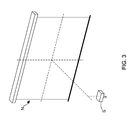
FIG. 3 shows stereo views of a video recorder and a projection screen;
FIG. 4 shows a projected image captured by the video recorder; and
FIG. 5 shows a flowchart diagram of a laser spot detecting and locating method according to the present invention.
DETAILED DESCRIPTION OF THE PREFERRED EMBODIMENTS
To more clearly describe a laser spot detecting and locating system and a method thereof disclosed by the present invention, embodiments of the present invention will be described in detail with reference to the attached drawings hereinafter.
Please refer to FIG. 1, which illustrates framework diagram of a laser spot detecting and locating system according to the present invention. Moreover, please simultaneously refer to FIG. 2, where a function block diagram of the laser spot detecting and locating system is provided. As FIG. 1 and FIG. 2 show, the laser spot detecting and locating system of the present invention is implemented in a computer projection system at least comprising a host computer C, a projection screen N, a laser pointer A, and a projector P, and mainly comprises: a video recorder S connected to the host computer C and a detecting module X installed in the host computer C. According to the particular design of the present invention, the host computer C utilizes the video recorder S to capture a projected image provided on the projection screen N by the projector P and simultaneously capture a laser spot L provided on the projection screen N by the laser pointer A.
On the other hand, the detecting module X comprises an exposure modulating unit X1, a light spot detecting unit X2, a coordinate conversion unit X3, and a mouse cursor controlling unit X4, wherein the light spot detecting unit X2 is configured for determining whether the laser spot L is emitted onto the projection screen N or not, and then detecting a laser spot coordinate. Therefore, the exposure modulating unit X1 is able to adjust an amount of exposure of the video recorder S based on the intensity of the laser spot, such that only the laser spot with high intensity would be image formed on image sensors of the video recorder S, and the projected image provided on the projection screen N would not be sensed and then formed on image sensors of the video recorder S. As a result, the laser spot coordinate can be precisely detected by the detecting module X, so as to facilitate the host computer C control a mouse cursor M to move and reach the laser spot coordinate. In addition, the coordinate conversion unit X3 is connected to the light spot detecting unit X2 for converting the laser spot coordinate to a screen coordinate in a displayed image of the host computer C. Moreover, the mouse cursor controlling unit X4 is connected to the coordinate conversion unit X3 and used for controlling the mouse cursor M to move and reach the screen coordinate.
Thus, during commercial presentation or classroom teaching, presentation processes and contents of a presenter and moving traces of the laser spot L can be simultaneously recorded by the video recorder S. Subsequently, by real time converting the coordinate of the laser spot L to the screen coordinate, the mouse cursor M of the host computer C is simultaneously moved to the corresponding screen coordinate with the motion of the laser spot L. As a result, the audiences can fully catch up the speeching or presentation contents anytime when receiving the information or contents provided by the presenter.
In the present invention, the image sensor of the video recorder S could be a CCD image sensor or a CMOS sensor. Moreover, it is worth explaining that, the exposure modulating unit X1 adjusts the amount of exposure by controlling the size of at least one lens aperture of the video recorder S or through modulating an exposure value (EV) of the video recorder S.
Continuously referring to FIG. 1, and please simultaneously refer to stereo views of the video recorder and the projection screen provided in FIG. 3. In the present invention, the video recorder S is disposed at front of the projection screen N, and must locates below a horizontal line elongating from a center coordinate of the projection screen N. Please simultaneously refer to FIG. 4, which illustrates a projected image captured by the video recorder. From FIG. 4, it is understood that the projected image captured by the video recorder S has an inverted trapezoid shape. Particularly, in the present invention, the projected image with the inverted trapezoid shape is converted to a crossed parallelogram image by the coordinate conversion unit X3, therefore the laser spot coordinate can be easily converted to the screen coordinate by a rotation matrix and a scaling matrix of the coordinate conversion unit X3. The rotation matrix is provided as follows.
[ uq vq q ] = [ e - fh ch - b bf - ce fg - d a - cg cd - af dh - eg bg - ah ae - bd ] [ x y 1 ] ( 1 )
Corresponding coordinates for four top points of the projected image with inverted trapezoid shape can be set as (x0, y0), (x1, y1), (x2, y2), and (x3, y3), respectively. Moreover, variables “u” and “v” in the mathematic equation (1) mean an X coordinate and a Y coordinate of any one point in the projected image been treated with the rotation matrix conversion. On the other hand, “q” in the mathematic equation (1) represents a constant, and others variables are introduced and described in following Table (1).
TABLE (1)
Variables Description
a a = x1 − x0 + gx1
b a = x3 − x0 + hx3
c c = x0
d d = y1 − t0 + gy1
e e = y3 − y0 + hy3
f f = x0
g g = [ Σ x Δ x 2 Σ y Δ y 2 ] [ Σ x 1 Δ x 2 Σ y1 Δ y 2 ]
h h = [ Δ x 1 Σ x Δ y 1 Σ x ] [ Δ x 1 Δ x 2 Δ y 1 Δ y 2 ]
Δx1 Δx1 = x1 − x2
Δx2 Δx2 = x3 − x2
Δy1 Δy1 = y1 − y2
Δy2 Δy2 = y3 − y2
Σx Σx = x0 − x1 + x2 − x3
Σy Σy = y0 − y1 + y2 − y3
In addition, the scaling matrix is provided as following mathematic equation (2). It must explains that, variables “X” and “Y” in the mathematic equation (2) mean an X coordinate and a Y coordinate of any one point in the projected image been treated with the scaling matrix conversion. On the other hand, “W” in the mathematic equation (2) represents a constant, and “P” and “Q” are the length and the width of resolution of the projected image been treated with the scaling matrix conversion.
Table ( 1 ) [ XW YW W ] = [ P 0 0 - P - Q - 2 0 0 1 ] [ u v 1 ] ( 2 )
Therefore, through above descriptions, the laser spot detecting and locating system of the present invention have been introduced completely and clearly. Next, a laser spot detecting and locating method of the present invention will be introduced in following paragraphs.
Continuously referring from FIG. 1 to FIG. 4, and please simultaneously refer to FIG. 5, where a flowchart diagram of the laser spot detecting and locating method according to the present invention is provided. As FIG. 5 shows, the laser spot detecting and locating method mainly comprises following four steps:
  • S01: using the video recorder S to capture a projected image provided on the projection screen by the projector P and simultaneously capture a laser spot provided on the projection screen by the laser pointer A;
  • S02: determining whether an amount of exposure of the video recorder S must be adjusted or not; if yes, proceeding to step (4); otherwise, proceeding to step (5);
  • S03: modulating the amount of exposure of the video recorder S by the detecting module X based on the intensity of the laser spot, such that only the image of the laser spot with high intensity can be formed on image sensors of the video recorder S, and the projected image provided on the projection screen N would not be sensed and then formed on image sensors of the video recorder S; and
  • S04: using the detecting module X to convert a laser spot coordinate to a screen coordinate in a displayed image of the host computer C, and simultaneously control a mouse cursor M to move and reach the screen coordinate.
In the step (S02), the way to determining whether an amount of exposure of the video recorder S must be adjusted or not is carried out by calculating the brightness difference between the laser spot L and the projected image provided on the projection screen by the projector P. When, executing exposure modulation, the exposure modulating unit X1 is configured to adjust the amount of exposure of the video recorder S, so as to make the exposure amount reach the lowest level. As a result, only the laser spot with high intensity would be image formed on image sensors of the video recorder S, and the projected image provided on the projection screen N would not be sensed and then formed on image sensors of the video recorder S. Therefore, the coordinate of the laser spot is precisely detected by the light spot detecting unit X2; moreover, after the laser spot coordinate is converted to a screen coordinate in a displayed image of the host computer C by the coordinate conversion unit X3, and the mouse cursor controlling unit X4 is able to control a mouse cursor M to move and reach the screen coordinate.
For realizing above-motioned technology features, the step (S04) is further designed to comprises following three detail steps:
  • S041: detecting the laser spot coordinate by a light spot detecting unit X2 of the detecting module X;
  • S042: converting the laser spot coordinate to the screen coordinate by a coordinate conversion unit X3 of the detecting module X; and
  • S043: controlling the mouse cursor M to move and reach the screen coordinate by a mouse cursor controlling unit X4 of the detecting module X.
Thus, above descriptions have introduced the laser spot detecting and locating system and method provided by the present invention completely and clearly. Next, a variety of experimental data will be provided in following paragraphs for proving the practicability of the system and the method. It is worth explaining that, there have two experiments been completed for obtaining the experimental data, wherein first of the two experiments includes an experimental group and a control group. Moreover, testing objects in the experimental group and the control group are respectively the laser spot detecting and locating system of the present invention and a modular stylus device disclosed by U.S. Patent Publication No. US2014/0028635 A1.
During the experiment, a mouse cursor and a laser spot are firstly set to have the same initial screen coordinate in a computer screen; and subsequently, the laser spot is moved from the initial screen coordinate to a center coordinate of the computer screen. It is noting that, the laser spot detecting and locating system is used for sensing the moving traces of the laser spot so as to simultaneously control the mouse cursor to move with the motion of the laser spot. Moreover, final coordinates of the laser spot and the mouse cursor are both recorded. Having the same experimental operation as the laser spot detecting and locating system, the modular stylus device disclosed by U.S. Patent Publication No. US2014/0028635 A1 is configured to emit a laser spot onto the computer screen and subsequently make the laser spot move from its initial coordinate to the center coordinate of the computer screen. Moreover, final coordinates of the laser spot and the mouse cursor are both recorded. Related experimental data are integrated and listed in following Table (2).
TABLE 2
Control Experiment Reduced pixel
Testing item group group distance error
Error of pixel 207 3.5 203.5
distance (pixel dots) (pixel dots) (pixel dots)
Error rate   30.3% 0.05% 30.25%
(Total number of
pixels is 683)
Experimental data of Table (2) reveals that, there is merely a minor difference of 3.5 pixel dots between the coordinate of laser spot and the coordinate of mouse cursor after the mouse cursor is controlled by laser spot detecting and locating system to move with the motion of the laser spot. However, compared to the laser spot detecting and locating system of the present invention, there is a large difference of 207 pixel dots between the coordinate of laser spot and the coordinate of mouse cursor after the mouse cursor is controlled by modular stylus device to move with the motion of the laser spot. As a result, related experimental data have proved that the laser spot detecting and locating system proposed by the present invention can indeed precisely detect the laser spot irradiated on the projection screen by a laser pointer, and is able to control the mouse cursor move with the motion of the laser spot immediately. On the other hand, the second experiment also includes an experimental group and a control group. Moreover, testing objects in the experimental group and the control group are respectively a video recorder S with an exposure modulating unit X1 and a video recorder S. During the second experiment, a laser pointer A is adopted for emitting a laser spot L onto a projection screen N, and then the two video recorders S are used to sense and capture the laser spot L. Following Table (3) shows the data of success rate of the laser spot given exposure by the two video recorders S.
TABLE 3
Control Experiment Increased success
group group rate
Success rate of 20% 100% 80%
the laser spot
given exposure
by the video
recorder
It is well known that, high-intensity laser spot is easy to be exposed as a white spot on image sensors of the video recorder S, such that the video recorder S cannot precisely sense and locate the coordinate of the high-intensity laser spot while the laser spot is emitted onto a projected image showing whole-white contents provided on the projection screen by a projector P. Experimental data of Table (3) reveals that, there is merely twenty-percent success rate that the high-intensity laser spot is exposed on the image sensors of the video recorder S (i.e., the control group). However, compared to the control group, the high-intensity laser spot can be exposed on the image sensors of the video recorder S having the exposure modulating unit X1 by 100% of exposure success rate.
Therefore, through above descriptions, the laser spot detecting and locating system and method proposed by the present invention have been introduced completely and clearly; in summary, the present invention includes the advantages of:
(1) By implemented this laser spot detecting and locating system or method in a computer projection system, presentation processes and contents of a presenter and moving traces of a laser spot can be simultaneously recorded by the video recorder for being further made as a video learning material during the presenter's commercial presentation or classroom teaching. As a result, audiences can fully catch up the speeching or presentation contents anytime when receiving the information or contents provided by the presenter through the video learning material.
(2) Moreover, owing to the fact that a high-intensity laser spot is easy to be exposed as a white spot on image sensors of the video recorder, the present invention further utilizes an exposure modulating unit to automatically adjust an amount of exposure of the video recorder based on the intensity of the laser spot, such that only the image of a laser spot with high intensity would be formed on images sensors of the video recorder, and the projected image provided on the projection screen would not be sensed and then formed on image sensors of the video recorder. Experimental data have proved that, high-intensity laser spot can be precisely sensed and located by the video recorder S having the exposure modulating unit X1 by 100% of exposure success rate.
The above description is made on embodiments of the present invention. However, the embodiments are not intended to limit scope of the present invention, and all equivalent implementations or alterations within the spirit of the present invention still fall within the scope of the present invention.

Claims (6)

What is claimed is:
1. A laser spot detecting and locating system, being implemented in a computer projection system at least comprising a host computer, a projection screen,
a video recorder, being electrically connected to the host computer, and used for capturing a projected image provided on the projection screen by the projector; and
a detecting module, being installed in the host computer and being configured to sense a laser spot on the projection screen through the video recorder; wherein the laser spot emitted from the laser pointer, and the detecting module having an exposure modulating unit and a coordinate conversion unit;
wherein the exposure modulating unit is configured to adjust an amount of exposure of the video recorder based on the intensity of the laser spot, such that only the laser spot with high intensity would be image formed on image sensors of the video recorder in the case of the projected image provided on the projection screen not being sensed and then formed on image sensors of the video recorder;
wherein a laser spot coordinate is detected by the detecting module, so as to facilitate the host computer capable of controlling a mouse cursor to correspondingly move and reach a screen coordinate in a displayed image of the host computer;
wherein the projected image captured by the video recorder has an inverted trapezoid shape, and the projected image with the inverted trapezoid shape being converted to a crossed parallelogram image by the coordinate conversion unit, therefore the laser spot coordinate is easily converted to the screen coordinate by a rotation matrix and a scaling matrix of the coordinate conversion unit.
2. The laser spot detecting and locating system of claim 1, wherein the detecting module further comprises:
a light spot detecting unit, being connected to the coordinate conversion unit and used for detecting the laser spot coordinate; and
a mouse cursor controlling unit, being connected to the coordinate conversion unit, and used for controlling the mouse cursor to move and reach the screen coordinate.
3. The laser spot detecting and locating system of claim 1, wherein the image sensor of the video recorder S is a CCD image sensor or a CMOS sensor.
4. The laser spot detecting and locating system of claim 1, wherein the exposure modulating unit adjusts the amount of exposure by controlling the size of at least one lens aperture of the video recorder.
5. The laser spot detecting and locating system of claim 1, wherein the exposure modulating unit adjusts the amount of exposure by modulating an exposure value (EV) of the video recorder.
6. The laser spot detecting and locating system of claim 2, wherein the video recorder is disposed at front of the projection screen, and locating below a horizontal line elongating from a center coordinate of the projection screen.
US15/836,930 2017-04-19 2017-12-11 Laser spot detecting and locating system and method thereof Expired - Fee Related US10198095B2 (en)

Applications Claiming Priority (3)

Application Number Priority Date Filing Date Title
TW106113048A TWI629617B (en) 2017-04-19 2017-04-19 Projection screen laser pointer detecting and locating system and the method for detecting and locating the same
TW106113048A 2017-04-19
TW106113048 2017-04-19

Publications (2)

Publication Number Publication Date
US20180307335A1 US20180307335A1 (en) 2018-10-25
US10198095B2 true US10198095B2 (en) 2019-02-05

Family

ID=63640379

Family Applications (1)

Application Number Title Priority Date Filing Date
US15/836,930 Expired - Fee Related US10198095B2 (en) 2017-04-19 2017-12-11 Laser spot detecting and locating system and method thereof

Country Status (2)

Country Link
US (1) US10198095B2 (en)
TW (1) TWI629617B (en)

Families Citing this family (6)

* Cited by examiner, † Cited by third party
Publication number Priority date Publication date Assignee Title
CN111462537A (en) * 2019-01-18 2020-07-28 郑州升达经贸管理学院 Multimedia teaching equipment for business administration and implementation method thereof
CN110221752A (en) * 2019-05-13 2019-09-10 北京云迹科技有限公司 Large-size screen monitors interactive system and exchange method
CN110274178A (en) * 2019-06-06 2019-09-24 聊城大学 A kind of intelligent illuminating system of tiny lattice classroom
CN110471545A (en) * 2019-08-09 2019-11-19 暨南大学 It is a kind of based on infrared image identification PPT delineate device and PPT delineation method
CN112631495A (en) * 2020-12-25 2021-04-09 深圳Tcl新技术有限公司 Interaction method based on laser induction, terminal equipment and computer readable storage medium
CN113639588A (en) * 2021-07-29 2021-11-12 彩虹无人机科技有限公司 Laser indication and detection modularized integrated system

Citations (8)

* Cited by examiner, † Cited by third party
Publication number Priority date Publication date Assignee Title
US20020011987A1 (en) * 2000-03-31 2002-01-31 Seiko Epson Corporation Detection of pointed position using image processing
US20060176377A1 (en) * 2005-02-04 2006-08-10 Seiko Epson Corporation Projector and exposure adjustment method
US20090021480A1 (en) * 2005-02-10 2009-01-22 Takram Design Engineering Pointer light tracking method, program, and recording medium thereof
US20110025818A1 (en) * 2006-11-07 2011-02-03 Jonathan Gallmeier System and Method for Controlling Presentations and Videoconferences Using Hand Motions
US20110221919A1 (en) * 2010-03-11 2011-09-15 Wenbo Zhang Apparatus, method, and system for identifying laser spot
US20140247216A1 (en) * 2011-11-08 2014-09-04 Tencent Technology (Shenzhen) Company Limited Trigger and control method and system of human-computer interaction operation command and laser emission device
US20150130717A1 (en) * 2013-11-08 2015-05-14 Seiko Epson Corporation Display apparatus, display system, and control method
US20160154472A1 (en) * 2014-12-01 2016-06-02 Seiko Epson Corporation Projector and method for controlling projector

Family Cites Families (5)

* Cited by examiner, † Cited by third party
Publication number Priority date Publication date Assignee Title
JP4697916B2 (en) * 2000-07-07 2011-06-08 キヤノン株式会社 Coordinate input device, control method therefor, and program
US7683881B2 (en) * 2004-05-24 2010-03-23 Keytec, Inc. Visual input pointing device for interactive display system
TWI438656B (en) * 2011-07-13 2014-05-21 Aletheia University Light-detecting (type) mouse simulating system and simulating method thereof
CN102622108B (en) * 2012-01-18 2015-11-04 深圳市中科睿成智能科技有限公司 A kind of interactive projection system and its implementation
CN104298372A (en) * 2014-11-13 2015-01-21 厦门美拓通信技术有限公司 Method for realizing virtual mouse and touch operation through laser pen

Patent Citations (8)

* Cited by examiner, † Cited by third party
Publication number Priority date Publication date Assignee Title
US20020011987A1 (en) * 2000-03-31 2002-01-31 Seiko Epson Corporation Detection of pointed position using image processing
US20060176377A1 (en) * 2005-02-04 2006-08-10 Seiko Epson Corporation Projector and exposure adjustment method
US20090021480A1 (en) * 2005-02-10 2009-01-22 Takram Design Engineering Pointer light tracking method, program, and recording medium thereof
US20110025818A1 (en) * 2006-11-07 2011-02-03 Jonathan Gallmeier System and Method for Controlling Presentations and Videoconferences Using Hand Motions
US20110221919A1 (en) * 2010-03-11 2011-09-15 Wenbo Zhang Apparatus, method, and system for identifying laser spot
US20140247216A1 (en) * 2011-11-08 2014-09-04 Tencent Technology (Shenzhen) Company Limited Trigger and control method and system of human-computer interaction operation command and laser emission device
US20150130717A1 (en) * 2013-11-08 2015-05-14 Seiko Epson Corporation Display apparatus, display system, and control method
US20160154472A1 (en) * 2014-12-01 2016-06-02 Seiko Epson Corporation Projector and method for controlling projector

Also Published As

Publication number Publication date
US20180307335A1 (en) 2018-10-25
TWI629617B (en) 2018-07-11
TW201839556A (en) 2018-11-01

Similar Documents

Publication Publication Date Title
US10198095B2 (en) Laser spot detecting and locating system and method thereof
EP1441514A2 (en) Interactive image projector
JP3909554B2 (en) Presentation control system and control method thereof
US6292171B1 (en) Method and apparatus for calibrating a computer-generated projected image
US8449122B2 (en) Image marking method and apparatus
US7830362B2 (en) Laser and digital camera computer pointer device system
CN114466173A (en) Projection equipment and projection display control method for automatically throwing screen area
JP2013168922A (en) Projection type image display device and image projection method, and computer program
JPWO2006085580A1 (en) Pointer light tracking method, program and recording medium therefor
US8408710B2 (en) Presentation recording apparatus and method
US9049369B2 (en) Apparatus, system and method for projecting images onto predefined portions of objects
JP2001125738A5 (en)
US9298246B2 (en) Information processing device, system, and information processing method
JP2011191298A (en) Device, method and system for identifying laser spot
US20020136455A1 (en) System and method for robust foreground and background image data separation for location of objects in front of a controllable display within a camera view
US9039537B2 (en) Light gun and method for determining shot position
US7119788B2 (en) Image processing apparatus, image processing method, providing medium and presentation system
KR20150062952A (en) Laser projector with position detecting capability and position detection method using the same
KR100917615B1 (en) Method and apparatus for detecting location of laser beam with minimized error using mono-camera
WO2021226821A1 (en) Systems and methods for detection and display of whiteboard text and/or an active speaker
US11431899B2 (en) Display method and display apparatus
CN102999233B (en) The noise spot automatic shield method and device of electronic whiteboard based on imageing sensor
KR101617738B1 (en) Real-time image mapping system and method for multi-object
JP2004198817A (en) Presentation device
JP2010157044A (en) Display device and light pen

Legal Events

Date Code Title Description
AS Assignment

Owner name: CHUNG-YUAN CHRISTIAN UNIVERSITY, TAIWAN

Free format text: ASSIGNMENT OF ASSIGNORS INTEREST;ASSIGNORS:LIN, TING-LAN;CHEN, SHIH-LUN;PAN, SZU-CHING;REEL/FRAME:044346/0322

Effective date: 20171006

FEPP Fee payment procedure

Free format text: ENTITY STATUS SET TO UNDISCOUNTED (ORIGINAL EVENT CODE: BIG.); ENTITY STATUS OF PATENT OWNER: SMALL ENTITY

FEPP Fee payment procedure

Free format text: ENTITY STATUS SET TO SMALL (ORIGINAL EVENT CODE: SMAL); ENTITY STATUS OF PATENT OWNER: SMALL ENTITY

STCF Information on status: patent grant

Free format text: PATENTED CASE

FEPP Fee payment procedure

Free format text: MAINTENANCE FEE REMINDER MAILED (ORIGINAL EVENT CODE: REM.); ENTITY STATUS OF PATENT OWNER: SMALL ENTITY

LAPS Lapse for failure to pay maintenance fees

Free format text: PATENT EXPIRED FOR FAILURE TO PAY MAINTENANCE FEES (ORIGINAL EVENT CODE: EXP.); ENTITY STATUS OF PATENT OWNER: SMALL ENTITY

STCH Information on status: patent discontinuation

Free format text: PATENT EXPIRED DUE TO NONPAYMENT OF MAINTENANCE FEES UNDER 37 CFR 1.362

FP Lapsed due to failure to pay maintenance fee

Effective date: 20230205