US10194154B2 - Methods and apparatus for embedded quantization parameter adjustment in video encoding and decoding - Google Patents
Methods and apparatus for embedded quantization parameter adjustment in video encoding and decoding Download PDFInfo
- Publication number
- US10194154B2 US10194154B2 US15/728,617 US201715728617A US10194154B2 US 10194154 B2 US10194154 B2 US 10194154B2 US 201715728617 A US201715728617 A US 201715728617A US 10194154 B2 US10194154 B2 US 10194154B2
- Authority
- US
- United States
- Prior art keywords
- quantization parameter
- picture
- block
- quantization
- variance
- Prior art date
- Legal status (The legal status is an assumption and is not a legal conclusion. Google has not performed a legal analysis and makes no representation as to the accuracy of the status listed.)
- Expired - Fee Related
Links
- 238000013139 quantization Methods 0.000 title claims abstract description 194
- 238000000034 method Methods 0.000 title claims abstract description 75
- 230000001131 transforming effect Effects 0.000 claims abstract description 11
- 238000009795 derivation Methods 0.000 claims description 19
- 241000023320 Luma <angiosperm> Species 0.000 claims description 6
- 239000011159 matrix material Substances 0.000 claims description 6
- OSWPMRLSEDHDFF-UHFFFAOYSA-N methyl salicylate Chemical compound COC(=O)C1=CC=CC=C1O OSWPMRLSEDHDFF-UHFFFAOYSA-N 0.000 claims description 6
- 230000006870 function Effects 0.000 description 73
- 238000004891 communication Methods 0.000 description 36
- 238000010586 diagram Methods 0.000 description 15
- 230000008901 benefit Effects 0.000 description 12
- 230000008569 process Effects 0.000 description 8
- 230000000007 visual effect Effects 0.000 description 7
- 230000000694 effects Effects 0.000 description 4
- 230000011664 signaling Effects 0.000 description 4
- 238000013459 approach Methods 0.000 description 2
- 238000004364 calculation method Methods 0.000 description 2
- 238000013461 design Methods 0.000 description 2
- 230000006872 improvement Effects 0.000 description 2
- 230000000873 masking effect Effects 0.000 description 2
- 238000012986 modification Methods 0.000 description 2
- 230000004048 modification Effects 0.000 description 2
- 230000008520 organization Effects 0.000 description 2
- 230000000153 supplemental effect Effects 0.000 description 2
- 238000012935 Averaging Methods 0.000 description 1
- 239000000470 constituent Substances 0.000 description 1
- 238000013500 data storage Methods 0.000 description 1
- 230000003993 interaction Effects 0.000 description 1
- 230000008447 perception Effects 0.000 description 1
- 230000002093 peripheral effect Effects 0.000 description 1
- 238000012545 processing Methods 0.000 description 1
- 230000009467 reduction Effects 0.000 description 1
- 230000007704 transition Effects 0.000 description 1
Images


Classifications
-
- H—ELECTRICITY
- H04—ELECTRIC COMMUNICATION TECHNIQUE
- H04N—PICTORIAL COMMUNICATION, e.g. TELEVISION
- H04N19/00—Methods or arrangements for coding, decoding, compressing or decompressing digital video signals
- H04N19/10—Methods or arrangements for coding, decoding, compressing or decompressing digital video signals using adaptive coding
- H04N19/134—Methods or arrangements for coding, decoding, compressing or decompressing digital video signals using adaptive coding characterised by the element, parameter or criterion affecting or controlling the adaptive coding
- H04N19/136—Incoming video signal characteristics or properties
-
- H—ELECTRICITY
- H04—ELECTRIC COMMUNICATION TECHNIQUE
- H04N—PICTORIAL COMMUNICATION, e.g. TELEVISION
- H04N19/00—Methods or arrangements for coding, decoding, compressing or decompressing digital video signals
- H04N19/10—Methods or arrangements for coding, decoding, compressing or decompressing digital video signals using adaptive coding
- H04N19/102—Methods or arrangements for coding, decoding, compressing or decompressing digital video signals using adaptive coding characterised by the element, parameter or selection affected or controlled by the adaptive coding
- H04N19/119—Adaptive subdivision aspects, e.g. subdivision of a picture into rectangular or non-rectangular coding blocks
-
- H—ELECTRICITY
- H04—ELECTRIC COMMUNICATION TECHNIQUE
- H04N—PICTORIAL COMMUNICATION, e.g. TELEVISION
- H04N19/00—Methods or arrangements for coding, decoding, compressing or decompressing digital video signals
- H04N19/10—Methods or arrangements for coding, decoding, compressing or decompressing digital video signals using adaptive coding
- H04N19/102—Methods or arrangements for coding, decoding, compressing or decompressing digital video signals using adaptive coding characterised by the element, parameter or selection affected or controlled by the adaptive coding
- H04N19/12—Selection from among a plurality of transforms or standards, e.g. selection between discrete cosine transform [DCT] and sub-band transform or selection between H.263 and H.264
- H04N19/122—Selection of transform size, e.g. 8x8 or 2x4x8 DCT; Selection of sub-band transforms of varying structure or type
-
- H—ELECTRICITY
- H04—ELECTRIC COMMUNICATION TECHNIQUE
- H04N—PICTORIAL COMMUNICATION, e.g. TELEVISION
- H04N19/00—Methods or arrangements for coding, decoding, compressing or decompressing digital video signals
- H04N19/10—Methods or arrangements for coding, decoding, compressing or decompressing digital video signals using adaptive coding
- H04N19/102—Methods or arrangements for coding, decoding, compressing or decompressing digital video signals using adaptive coding characterised by the element, parameter or selection affected or controlled by the adaptive coding
- H04N19/124—Quantisation
-
- H—ELECTRICITY
- H04—ELECTRIC COMMUNICATION TECHNIQUE
- H04N—PICTORIAL COMMUNICATION, e.g. TELEVISION
- H04N19/00—Methods or arrangements for coding, decoding, compressing or decompressing digital video signals
- H04N19/10—Methods or arrangements for coding, decoding, compressing or decompressing digital video signals using adaptive coding
- H04N19/134—Methods or arrangements for coding, decoding, compressing or decompressing digital video signals using adaptive coding characterised by the element, parameter or criterion affecting or controlling the adaptive coding
- H04N19/136—Incoming video signal characteristics or properties
- H04N19/137—Motion inside a coding unit, e.g. average field, frame or block difference
-
- H—ELECTRICITY
- H04—ELECTRIC COMMUNICATION TECHNIQUE
- H04N—PICTORIAL COMMUNICATION, e.g. TELEVISION
- H04N19/00—Methods or arrangements for coding, decoding, compressing or decompressing digital video signals
- H04N19/10—Methods or arrangements for coding, decoding, compressing or decompressing digital video signals using adaptive coding
- H04N19/134—Methods or arrangements for coding, decoding, compressing or decompressing digital video signals using adaptive coding characterised by the element, parameter or criterion affecting or controlling the adaptive coding
- H04N19/136—Incoming video signal characteristics or properties
- H04N19/14—Coding unit complexity, e.g. amount of activity or edge presence estimation
-
- H—ELECTRICITY
- H04—ELECTRIC COMMUNICATION TECHNIQUE
- H04N—PICTORIAL COMMUNICATION, e.g. TELEVISION
- H04N19/00—Methods or arrangements for coding, decoding, compressing or decompressing digital video signals
- H04N19/10—Methods or arrangements for coding, decoding, compressing or decompressing digital video signals using adaptive coding
- H04N19/134—Methods or arrangements for coding, decoding, compressing or decompressing digital video signals using adaptive coding characterised by the element, parameter or criterion affecting or controlling the adaptive coding
- H04N19/146—Data rate or code amount at the encoder output
- H04N19/147—Data rate or code amount at the encoder output according to rate distortion criteria
-
- H—ELECTRICITY
- H04—ELECTRIC COMMUNICATION TECHNIQUE
- H04N—PICTORIAL COMMUNICATION, e.g. TELEVISION
- H04N19/00—Methods or arrangements for coding, decoding, compressing or decompressing digital video signals
- H04N19/10—Methods or arrangements for coding, decoding, compressing or decompressing digital video signals using adaptive coding
- H04N19/134—Methods or arrangements for coding, decoding, compressing or decompressing digital video signals using adaptive coding characterised by the element, parameter or criterion affecting or controlling the adaptive coding
- H04N19/157—Assigned coding mode, i.e. the coding mode being predefined or preselected to be further used for selection of another element or parameter
- H04N19/159—Prediction type, e.g. intra-frame, inter-frame or bidirectional frame prediction
-
- H—ELECTRICITY
- H04—ELECTRIC COMMUNICATION TECHNIQUE
- H04N—PICTORIAL COMMUNICATION, e.g. TELEVISION
- H04N19/00—Methods or arrangements for coding, decoding, compressing or decompressing digital video signals
- H04N19/10—Methods or arrangements for coding, decoding, compressing or decompressing digital video signals using adaptive coding
- H04N19/169—Methods or arrangements for coding, decoding, compressing or decompressing digital video signals using adaptive coding characterised by the coding unit, i.e. the structural portion or semantic portion of the video signal being the object or the subject of the adaptive coding
- H04N19/17—Methods or arrangements for coding, decoding, compressing or decompressing digital video signals using adaptive coding characterised by the coding unit, i.e. the structural portion or semantic portion of the video signal being the object or the subject of the adaptive coding the unit being an image region, e.g. an object
- H04N19/176—Methods or arrangements for coding, decoding, compressing or decompressing digital video signals using adaptive coding characterised by the coding unit, i.e. the structural portion or semantic portion of the video signal being the object or the subject of the adaptive coding the unit being an image region, e.g. an object the region being a block, e.g. a macroblock
-
- H—ELECTRICITY
- H04—ELECTRIC COMMUNICATION TECHNIQUE
- H04N—PICTORIAL COMMUNICATION, e.g. TELEVISION
- H04N19/00—Methods or arrangements for coding, decoding, compressing or decompressing digital video signals
- H04N19/10—Methods or arrangements for coding, decoding, compressing or decompressing digital video signals using adaptive coding
- H04N19/169—Methods or arrangements for coding, decoding, compressing or decompressing digital video signals using adaptive coding characterised by the coding unit, i.e. the structural portion or semantic portion of the video signal being the object or the subject of the adaptive coding
- H04N19/18—Methods or arrangements for coding, decoding, compressing or decompressing digital video signals using adaptive coding characterised by the coding unit, i.e. the structural portion or semantic portion of the video signal being the object or the subject of the adaptive coding the unit being a set of transform coefficients
-
- H—ELECTRICITY
- H04—ELECTRIC COMMUNICATION TECHNIQUE
- H04N—PICTORIAL COMMUNICATION, e.g. TELEVISION
- H04N19/00—Methods or arrangements for coding, decoding, compressing or decompressing digital video signals
- H04N19/10—Methods or arrangements for coding, decoding, compressing or decompressing digital video signals using adaptive coding
- H04N19/169—Methods or arrangements for coding, decoding, compressing or decompressing digital video signals using adaptive coding characterised by the coding unit, i.e. the structural portion or semantic portion of the video signal being the object or the subject of the adaptive coding
- H04N19/186—Methods or arrangements for coding, decoding, compressing or decompressing digital video signals using adaptive coding characterised by the coding unit, i.e. the structural portion or semantic portion of the video signal being the object or the subject of the adaptive coding the unit being a colour or a chrominance component
-
- H—ELECTRICITY
- H04—ELECTRIC COMMUNICATION TECHNIQUE
- H04N—PICTORIAL COMMUNICATION, e.g. TELEVISION
- H04N19/00—Methods or arrangements for coding, decoding, compressing or decompressing digital video signals
- H04N19/10—Methods or arrangements for coding, decoding, compressing or decompressing digital video signals using adaptive coding
- H04N19/189—Methods or arrangements for coding, decoding, compressing or decompressing digital video signals using adaptive coding characterised by the adaptation method, adaptation tool or adaptation type used for the adaptive coding
- H04N19/196—Methods or arrangements for coding, decoding, compressing or decompressing digital video signals using adaptive coding characterised by the adaptation method, adaptation tool or adaptation type used for the adaptive coding being specially adapted for the computation of encoding parameters, e.g. by averaging previously computed encoding parameters
- H04N19/197—Methods or arrangements for coding, decoding, compressing or decompressing digital video signals using adaptive coding characterised by the adaptation method, adaptation tool or adaptation type used for the adaptive coding being specially adapted for the computation of encoding parameters, e.g. by averaging previously computed encoding parameters including determination of the initial value of an encoding parameter
-
- H—ELECTRICITY
- H04—ELECTRIC COMMUNICATION TECHNIQUE
- H04N—PICTORIAL COMMUNICATION, e.g. TELEVISION
- H04N19/00—Methods or arrangements for coding, decoding, compressing or decompressing digital video signals
- H04N19/44—Decoders specially adapted therefor, e.g. video decoders which are asymmetric with respect to the encoder
-
- H—ELECTRICITY
- H04—ELECTRIC COMMUNICATION TECHNIQUE
- H04N—PICTORIAL COMMUNICATION, e.g. TELEVISION
- H04N19/00—Methods or arrangements for coding, decoding, compressing or decompressing digital video signals
- H04N19/46—Embedding additional information in the video signal during the compression process
- H04N19/463—Embedding additional information in the video signal during the compression process by compressing encoding parameters before transmission
-
- H—ELECTRICITY
- H04—ELECTRIC COMMUNICATION TECHNIQUE
- H04N—PICTORIAL COMMUNICATION, e.g. TELEVISION
- H04N19/00—Methods or arrangements for coding, decoding, compressing or decompressing digital video signals
- H04N19/60—Methods or arrangements for coding, decoding, compressing or decompressing digital video signals using transform coding
- H04N19/61—Methods or arrangements for coding, decoding, compressing or decompressing digital video signals using transform coding in combination with predictive coding
-
- H—ELECTRICITY
- H04—ELECTRIC COMMUNICATION TECHNIQUE
- H04N—PICTORIAL COMMUNICATION, e.g. TELEVISION
- H04N19/00—Methods or arrangements for coding, decoding, compressing or decompressing digital video signals
- H04N19/70—Methods or arrangements for coding, decoding, compressing or decompressing digital video signals characterised by syntax aspects related to video coding, e.g. related to compression standards
-
- H—ELECTRICITY
- H04—ELECTRIC COMMUNICATION TECHNIQUE
- H04N—PICTORIAL COMMUNICATION, e.g. TELEVISION
- H04N19/00—Methods or arrangements for coding, decoding, compressing or decompressing digital video signals
- H04N19/85—Methods or arrangements for coding, decoding, compressing or decompressing digital video signals using pre-processing or post-processing specially adapted for video compression
- H04N19/86—Methods or arrangements for coding, decoding, compressing or decompressing digital video signals using pre-processing or post-processing specially adapted for video compression involving reduction of coding artifacts, e.g. of blockiness
Definitions
- the present principles relate generally to video encoding and decoding and, more particularly, to methods and apparatus for embedded quantization parameter adjustment in video encoding and decoding.
- a video encoder may provide higher quality by eliminating the strong visual artifacts at the regions of interest that are visually more important.
- visually lossless quality is expected everywhere in the pictures and a video encoder needs to also achieve transparent visual quality.
- One challenge in obtaining transparent visual quality in high bit rate applications is to preserve details, especially at smooth regions where the loss of details is more visible than at the non-smooth regions because of the texture masking property of the human visual system.
- VBR variable-bit-rate
- CBR constant-bit-rate
- an encoder can allocate bits according to perceptual models within a picture.
- One characteristic of human perception is texture masking, which explains why human eyes are more sensitive to loss of quality in smooth regions than in textured regions. This property can be utilized to increase the number of bits allocated to smooth regions in order to obtain a high visual quality.
- the quantization process in a video encoder controls the number of encoded bits and the quality. It is common to adjust the quality by adjusting the quantization parameters (QPs).
- the quantization parameters may include a quantization step size, a rounding offset, and a scaling matrix.
- the quantization parameter values are sent explicitly in the bitstream.
- the encoder has the flexibility to tune quantization parameters and signal the quantization parameters to the decoder.
- the quantization parameter signaling disadvantageously incurs an overhead cost.
- N ⁇ _act j 2 ⁇ act j + avg_act act j + 2 ⁇ avg_ ⁇ act , ( 4 ) where avg_act is the average value of act j of the previous encoded picture.
- avg_act is set to 400.
- the final value of mquant j is clipped to the range [1 . . . 31] and is used to indicate the quantization step size during encoding.
- a smooth macroblock with a smaller variance has a smaller value of a spatial activity measure act j and a smaller value of N_act j , as well as a finer quantization step size indexed by mquant j .
- finer quantization for a smooth macroblock finer details can be preserved and a higher perceptual quality is obtained.
- the index mquant j is sent in the bitstream to the decoder.
- the syntax in the International Organization for Standardization/International Electrotechnical Commission (ISO/IEC) Moving Picture Experts Group-4 (MPEG-4) Part 10 Advanced Video Coding (AVC) Standard/International Telecommunication Union, Telecommunication Sector (ITU-T) H.264 Recommendation also allows quantization parameters to be different for each picture and macroblock.
- the value of a quantization parameter is an integer and in the range of 0-51.
- the initial value for each slice can be derived from the syntax element pic_init_qp_minus26. The initial value is modified at the slice layer when a non-zero value of slice_qp_delta is decoded, and is modified further when a non-zero value of mb_qp_delta is decoded at the macroblock layer.
- the method 100 includes a start block 105 that passes control to a function block 110 .
- the function block 110 analyzes the input video content, and passes control to a loop limit block 115 .
- the loop limit block 115 begins a loop over each macroblock in a picture using a variable i having a range from 1 to the # of macroblocks (MBs), and passes control to a function block 120 .
- the function block 120 adjusts a quantization parameter for a current macroblock i, and passes control to a function block 125 .
- the function block 125 encodes the quantization parameter and the macroblock i, and passes control to a loop limit block 130 .
- the loop limit block 130 ends the loop over each macroblock, and passes control to an end block 199 .
- the quantization parameter adjustment is explicitly signaled.
- the quantization parameter for the macroblock i is adjusted based on its content and/or the previous encoding results. For example, a smooth macroblock will lower the quantization parameter to improve the perceptual quality. In another example, if the previous macroblocks use more bits than assigned ones, the current macroblock will increase the quantization parameter to consume fewer bits than what is originally assigned.
- the method 100 ends after all macroblock in the picture are encoded.
- the method 200 includes a start block 205 that passes control to a loop limit block 210 .
- the loop limit block 210 begins a loop over each macroblock in a picture using a variable i having a range from 1 to the # of macroblocks (MBs), and passes control to a function block 215 .
- the function block 215 decodes the quantization parameter and a current macroblock i, and passes control to a loop limit block 220 .
- the loop limit block 220 ends the loop over each macroblock, and passes control to an end block 299 .
- the existing standards support adjusting picture-level and macroblock-level quantization parameters in the encoder to achieve high perceptual quality.
- the quantization parameter values are absolutely or differentially encoded and are thus explicitly sent in the bitstream.
- the encoder has the flexibility to tune quantization parameters and signal the quantization parameters to the decoder.
- the explicit quantization parameter signaling disadvantageously incurs an overhead cost.
- an apparatus includes an encoder for encoding picture data for at least a block in a picture.
- a quantization parameter applied to one or more transform coefficients obtained by transforming a difference between an original version of the block and at least one reference block, is derived from reconstructed data corresponding to at least the block.
- a method in a video encoder includes encoding picture data for at least a block in a picture.
- a quantization parameter, applied to one or more transform coefficients obtained by transforming a difference between an original version of the block and at least one reference block, is derived from reconstructed data corresponding to at least the block.
- an apparatus includes a decoder for decoding picture data for at least a block in a picture.
- a quantization parameter, applied to one or more transform coefficients obtained by transforming a difference between an original version of the block and at least one reference block, is derived from reconstructed data corresponding to at least the block.
- a method in a video decoder includes decoding picture data for at least a block in a picture.
- a quantization parameter, applied to one or more transform coefficients obtained by transforming a difference between an original version of the block and at least one reference block, is derived from reconstructed data corresponding to at least the block.
- FIG. 1 is a flow diagram showing a typical quantization adjustment method for improving the perceptual quality in a video encoder, in accordance with the prior art
- FIG. 2 is a flow diagram showing a typical method for decoding a quantization parameter and macroblock in a video decoder, in accordance with the prior art
- FIG. 3 is a block diagram showing an exemplary video encoder to which the present principles may be applied, in accordance with an embodiment of the present principles
- FIG. 4 is a block diagram showing an exemplary video decoder to which the present principles may be applied, in accordance with an embodiment of the present principles
- FIG. 5 is a flow diagram showing an exemplary method for embedding a quantization parameter map in a bitstream, in accordance with an embodiment of the present principles
- FIG. 6 is a flow diagram showing an exemplary method for decoding an embedded quantization parameter map, in accordance with an embodiment of the present principles
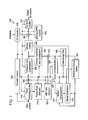
- FIG. 7 is a flow diagram showing an exemplary method for encoding an explicit quantization parameter adjustment in conjunction with the use of an embedded quantization parameter map, in accordance with an embodiment of the present principles
- FIG. 8 is a flow diagram showing an exemplary method for decoding an explicit quantization parameter adjustment in conjunction with the use of an embedded quantization parameter map, in accordance with an embodiment of the present principles
- FIG. 9 is a flow diagram showing an exemplary method for assigning quantization parameters in a video encoder, in accordance with an embodiment of the present principles
- FIG. 10 is a flow diagram showing an exemplary method for calculating quantization parameters in a video decoder, in accordance with an embodiment of the present principles
- FIG. 11 is a flow diagram showing an exemplary method for assigning quantization parameters in a video encoder, in accordance with an embodiment of the present principles.
- FIG. 12 is a flow diagram showing an exemplary method for calculating quantization parameters in a video decoder, in accordance with an embodiment of the present principles.
- the present principles are directed to methods and apparatus for embedded quantization parameter adjustment in video encoding and decoding.
- processor or “controller” should not be construed to refer exclusively to hardware capable of executing software, and may implicitly include, without limitation, digital signal processor (“DSP”) hardware, read-only memory (“ROM”) for storing software, random access memory (“RAM”), and non-volatile storage.
- DSP digital signal processor
- ROM read-only memory
- RAM random access memory
- any switches shown in the figures are conceptual only. Their function may be carried out through the operation of program logic, through dedicated logic, through the interaction of program control and dedicated logic, or even manually, the particular technique being selectable by the implementer as more specifically understood from the context.
- any element expressed as a means for performing a specified function is intended to encompass any way of performing that function including, for example, a) a combination of circuit elements that performs that function or b) software in any form, including, therefore, firmware, microcode or the like, combined with appropriate circuitry for executing that software to perform the function.
- the present principles as defined by such claims reside in the fact that the functionalities provided by the various recited means are combined and brought together in the manner which the claims call for. It is thus regarded that any means that can provide those functionalities are equivalent to those shown herein.
- any of the following “/”, “and/or”, and “at least one of”, for example, in the cases of “A/B”, “A and/or B” and “at least one of A and B”, is intended to encompass the selection of the first listed option (A) only, or the selection of the second listed option (B) only, or the selection of both options (A and B).
- such phrasing is intended to encompass the selection of the first listed option (A) only, or the selection of the second listed option (B) only, or the selection of the third listed option (C) only, or the selection of the first and the second listed options (A and B) only, or the selection of the first and third listed options (A and C) only, or the selection of the second and third listed options (B and C) only, or the selection of all three options (A and B and C).
- This may be extended, as readily apparent by one of ordinary skill in this and related arts, for as many items listed.
- a picture and “image” are used interchangeably and refer to a still image or a picture from a video sequence.
- a picture may be a frame or a field.
- the word “signal” refers to indicating something to a corresponding decoder.
- the encoder may signal one or more quantization parameters in an embedded quantization parameter map in order to make the decoder aware of which particular one or more quantization parameters were used on the encoder side. In this way, the same quantization parameters may be used at both the encoder side and the decoder side.
- an encoder may embed a quantization parameter map in a bitstream sent to a decoder so that the decoder may use the same quantization parameters (specified in the map) as the encoder.
- signaling may be accomplished in a variety of ways. For example, one or more syntax elements, flags, and so forth may be used to signal information to a corresponding decoder.
- the quantization parameter adjustment process described herein is primarily described with respect to a macroblock for illustrative purposes, the quantization parameter adjustment process of the present principles may be applied to any of a sub-macroblock, a macroblock, a group of macroblocks, or any other coding units.
- the word “block” may refer to a macroblock or a sub-macroblock.
- the quantization parameters may be adjusted based on various criteria and so forth including, but not limited to, luma and/or chroma components.
- the video encoder 300 includes a frame ordering buffer 310 having an output in signal communication with a non-inverting input of a combiner 385 .
- An output of the combiner 385 is connected in signal communication with a first input of a transformer and quantizer 325 .
- An output of the transformer and quantizer 325 is connected in signal communication with a first input of an entropy coder 345 and a first input of an inverse transformer and inverse quantizer 350 .
- An output of the entropy coder 345 is connected in signal communication with a first non-inverting input of a combiner 390 .
- An output of the combiner 390 is connected in signal communication with a first input of an output buffer 335 .
- a first output of an encoder controller 305 is connected in signal communication with a second input of the frame ordering buffer 310 , a second input of the inverse transformer and inverse quantizer 350 , an input of a picture-type decision module 315 , a first input of a macroblock-type (MB-type) decision module 320 , a second input of an intra prediction module 360 , a second input of a deblocking filter 365 , a first input of a motion compensator 370 , a first input of a motion estimator 375 , and a second input of a reference picture buffer 380 .
- MB-type macroblock-type
- a second output of the encoder controller 305 is connected in signal communication with a first input of a Supplemental Enhancement Information (SEI) inserter 330 , a second input of the transformer and quantizer 325 , a second input of the entropy coder 345 , a second input of the output buffer 335 , and an input of the Sequence Parameter Set (SPS) and Picture Parameter Set (PPS) inserter 340 .
- SEI Supplemental Enhancement Information
- An output of the SEI inserter 330 is connected in signal communication with a second non-inverting input of the combiner 390 .
- a first output of the picture-type decision module 315 is connected in signal communication with a third input of the frame ordering buffer 310 .
- a second output of the picture-type decision module 315 is connected in signal communication with a second input of a macroblock-type decision module 320 .
- SPS Sequence Parameter Set
- PPS Picture Parameter Set
- An output of the inverse quantizer and inverse transformer 350 is connected in signal communication with a first non-inverting input of a combiner 319 .
- An output of the combiner 319 is connected in signal communication with a first input of the intra prediction module 360 and a first input of the deblocking filter 365 .
- An output of the deblocking filter 365 is connected in signal communication with a first input of a reference picture buffer 380 .
- An output of the reference picture buffer 380 is connected in signal communication with a second input of the motion estimator 375 and a third input of the motion compensator 370 .
- a first output of the motion estimator 375 is connected in signal communication with a second input of the motion compensator 370 .
- a second output of the motion estimator 375 is connected in signal communication with a third input of the entropy coder 345 .
- An output of the motion compensator 370 is connected in signal communication with a first input of a switch 397 .
- An output of the intra prediction module 360 is connected in signal communication with a second input of the switch 397 .
- An output of the macroblock-type decision module 320 is connected in signal communication with a third input of the switch 397 .
- the third input of the switch 397 determines whether or not the “data” input of the switch (as compared to the control input, i.e., the third input) is to be provided by the motion compensator 370 or the intra prediction module 360 .
- the output of the switch 397 is connected in signal communication with a second non-inverting input of the combiner 319 and an inverting input of the combiner 385 .
- a first input of the frame ordering buffer 310 and an input of the encoder controller 305 are available as inputs of the encoder 100 , for receiving an input picture.
- a second input of the Supplemental Enhancement Information (SEI) inserter 330 is available as an input of the encoder 300 , for receiving metadata.
- An output of the output buffer 335 is available as an output of the encoder 300 , for outputting a bitstream.
- SEI Supplemental Enhancement Information
- the video decoder 400 includes an input buffer 410 having an output connected in signal communication with a first input of an entropy decoder 445 .
- a first output of the entropy decoder 445 is connected in signal communication with a first input of an inverse transformer and inverse quantizer 450 .
- An output of the inverse transformer and inverse quantizer 450 is connected in signal communication with a second non-inverting input of a combiner 425 .
- An output of the combiner 425 is connected in signal communication with a second input of a deblocking filter 465 and a first input of an intra prediction module 460 .
- a second output of the deblocking filter 465 is connected in signal communication with a first input of a reference picture buffer 480 .
- An output of the reference picture buffer 480 is connected in signal communication with a second input of a motion compensator 470 .
- a second output of the entropy decoder 445 is connected in signal communication with a third input of the motion compensator 470 , a first input of the deblocking filter 465 , and a third input of the intra predictor 460 .
- a third output of the entropy decoder 445 is connected in signal communication with an input of a decoder controller 405 .
- a first output of the decoder controller 405 is connected in signal communication with a second input of the entropy decoder 445 .
- a second output of the decoder controller 405 is connected in signal communication with a second input of the inverse transformer and inverse quantizer 450 .
- a third output of the decoder controller 405 is connected in signal communication with a third input of the deblocking filter 465 .
- a fourth output of the decoder controller 405 is connected in signal communication with a second input of the intra prediction module 460 , a first input of the motion compensator 470 , and a second input of the reference picture buffer 480 .
- An output of the motion compensator 470 is connected in signal communication with a first input of a switch 497 .
- An output of the intra prediction module 460 is connected in signal communication with a second input of the switch 497 .
- An output of the switch 497 is connected in signal communication with a first non-inverting input of the combiner 425 .
- An input of the input buffer 410 is available as an input of the decoder 400 , for receiving an input bitstream.
- a first output of the deblocking filter 465 is available as an output of the decoder 400 , for outputting an output picture.
- the present principles are directed to methods and apparatus for embedded quantization parameter adjustment in video encoding and decoding.
- the same quantization parameter adjustment process is used at the encoder and decoder without explicitly sending quantization parameter information. This results in improved perceptual quality in the reconstructed video with little or no block-level quantization parameter overhead.
- embedding adjusted block-level quantization parameters in accordance with the present principles in addition to the aforementioned explicit block-level quantization parameters used by the prior art can provide additional quantization parameter adjustment flexibility.
- the quantization parameters are implicitly derived from the reconstructed data using the same method at both the encoder and decoder.
- adjusted and embedded quantization parameters in accordance with the present principles can be used in conjunction with the aforementioned explicitly signaled quantization parameters of the prior art to obtain further flexibility among other advantages readily apparent to one of ordinary skill in this and related arts.
- the quantization parameters need to be adjusted based on the global property of the picture and the local property of individual blocks.
- the phrase “global property” refers to a property derived from all blocks within the picture.
- a global property can be, but is not limited to, the average variance or average pixel value of the picture.
- the phrase “local property” refers to a property of a macroblock.
- a local property can be, but is not limited to, the variance or the average pixel value of a macroblock. Examples of how the global property of the picture and local property of the individual blocks are calculated are described below.
- the present principles allow for an improvement in the quality of regions where a loss of quality is more noticeable and can optionally allow a reduction in the quality of the remaining regions (or portions thereof) to save bits.
- the method 500 includes a start block 505 that passes control to a function block 510 .
- the function block 510 analyzes input video content, sends global feature information determined from the preceding analysis, and passes control to a loop limit block 515 .
- the loop limit block 515 begins a loop over each macroblock in a picture using a variable i having a range from 1 to the # of macroblocks (MBs), and passes control to function block 520 .
- the function block 520 derives the quantization parameter for a current macroblock i using the global feature information, and passes control to a function block 525 .
- the function block 525 encodes the current macroblock i using the derived quantization parameter, and passes control to a loop limit block 530 .
- the function block 530 ends the loop over each of the macroblocks, and passes control to an end block 599 .
- the method 600 includes a start block 605 that passes control to a function block 610 .
- the function block 610 decodes global feature information from a received bitstream, and passes control to a loop limit block 615 .
- the loop limit block 615 begins a loop over each macroblock in a picture using a variable i having a range from 1 to the # of macroblocks (MBs), and passes control to function block 620 .
- the function block 620 derives the quantization parameter for a current macroblock i, and passes control to a function block 625 .
- the function block 625 decodes the current macroblock using the derived quantization parameter, and passes control to a loop limit block 630 .
- the loop limit block 630 ends the loop over each macroblock, and passes control to an end block 699 .
- an embodiment that supports explicit quantization parameter adjustment on a macroblock level in addition to the embedded QP.
- the method 700 includes a start block 705 that passes control to a function block 710 .
- the function block 710 analyzes input video content, sends global feature information, and passes control to a loop limit block 715 .
- the loop limit block 715 begins a loop over each macroblock in a picture using a variable i having a range from 1 to the # of macroblocks (MBs), and passes control to function block 720 .
- the function block 720 derives a quantization parameter QP 0 for a current macroblock i, and passes control to a function block 725 .
- the function block 725 adjusts a quantization parameter offset QP d for the current macroblock i, and passes control to a function block 730 .
- the function block 730 encodes the quantization parameter offset QP d and macroblock i, and passes control to a loop limit block 735 .
- the loop limit block 735 ends the loop over each macroblock, and passes control to an end block 799 .
- the function block 725 can further tune the macroblock-level quantization parameter by the quantization parameter offset QP d .
- the macroblock is encoded at a quantization parameter of QP 0 +QP d , and the offset QP d is also encoded.
- an exemplary method for decoding an explicit quantization parameter adjustment in conjunction with the use of an embedded quantization parameter map is indicated generally by the reference numeral 800 .
- the method 800 includes a start block 805 that passes control to a function block 810 .
- the function block 810 decodes global feature information, and passes control to a loop limit block 815 .
- the loop limit block 815 begins a loop over each macroblock in a picture using a variable i having a range from 1 to the # of macroblocks (MBs), and passes control to function block 820 .
- the function block 820 decodes a quantization parameter offset QP d and derives a quantization parameter QP 0 for a current macroblock i, and passes control to a function block 825 .
- the function block 825 decodes macroblock i, and passes control to a loop limit block 830 .
- the loop limit block 830 ends the loop over each macroblock, and passes control to an end block 899 .
- a general guideline for quantization parameter adjustment is to assign lower quantization parameters to the regions of interest to improve the perceptual quality and higher quantization parameters to other areas to reduce the number of bits.
- quantization parameters using the spatial activity of the picture measured in variance. For each block, the variance can be calculated using all pixels in the block or a subset of them.
- the average spatial activity (avg_var) is calculated by averaging the variance over all the blocks in a picture.
- avg_var is large, them the overall picture is textured, and otherwise smooth.
- the information avg_var needs to be encoded and sent in the bitstream.
- a downscaled version of avg_var can be used.
- the quantization parameter For each macroblock, we derive the quantization parameter based on avg_var and the local variance (var). Since the local variance is used at both the encoder and decoder, only previously reconstructed information can be used. In one embodiment, we use the average variance of the neighboring blocks, such as left, upper, and/or upper-left blocks. In another embodiment, we use the minimum variance of the neighboring blocks. In yet another embodiment, we use the median value of the variances.
- ⁇ is a parameter that should be known at both the encoder and decoder
- QP pic is the base quantization parameter for the picture.
- ⁇ controls how strong the QP variation depends on the ratio between var and avg_var, var/avg_var.
- Equation (8) assigns a smaller quantization parameter to a macroblock where it is smooth and has a small variance.
- Equation (8) a look-up table can be used.
- the quantization parameter as set forth using the following pseudo code:
- the method 900 includes a start block 905 that passes control to a function block 910 .
- the function block 910 analyzes the global property of the picture, and passes control to a loop limit block 915 .
- the loop limit block 915 begins a loop using a variable i having a range from 1 to the number (#) of macroblocks (e.g., in a current picture), and passes control to a function block 920 .
- the function block 920 detects the importance of a current macroblock, and passes control to a function block 925 .
- the function block 925 assigns the quantization parameters as follows, and passes control to a loop limit block 930 : the more important the macroblock, the lower the quantization parameter that is assigned thereto, wherein the quantization parameter can be a quantization step size, a rounding offset, and/or a scaling matrix.
- the loop limit block 930 ends the loop, and passes control to an end block 999 .
- the method 1000 includes a start block 1005 that passes control to a function block 1010 .
- the function block 1010 decodes the global property of the picture, and passes control to a loop limit block 1015 .
- the loop limit block 1015 begins a loop using a variable i having a range from 1 to the number (#) of macroblocks (e.g., in a current picture), and passes control to a function block 1020 .
- the function block 1020 detects the importance of a current macroblock, and passes control to a function block 1025 .
- the function block 1025 calculates the quantization parameters using the same rule as in the encoder, and passes control to a loop limit block 1030 .
- the quantization parameter can be a quantization step size, a rounding offset, and/or a scaling matrix.
- the loop limit block 1030 ends the loop, and passes control to an end block 1099 .
- the method 1100 includes a start block 1105 that passes control to a function block 1110 .
- the function block 1110 calculates the average variance (avg_var) using all blocks, and passes control to a loop limit block 1115 .
- the loop limit block 1115 begins a loop using a variable i having a range from 1 to the number (#) of macroblocks (e.g., in a current picture), and passes control to a function block 1120 .
- the function block 1120 calculates the variance from neighboring blocks where such variance can be, but is not limited to, the average, minimum, or median of variances of the neighboring blocks, and passes control to a function block 1125 .
- the function block 1125 calculates the quantization parameter based on Equation (8) or Equation (9), and passes control to a loop limit block 1130 .
- the loop limit block 1130 ends the loop, and passes control to an end block 1199 .
- the method 1200 includes a start block 1205 that passes control to a function block 1210 .
- the function block 1210 decodes the average variance (avg_var), and passes control to a loop limit block 1215 .
- the loop limit block 1215 begins a loop using a variable i having a range from 1 to the number (#) of macroblocks (e.g., in a current picture), and passes control to a function block 1220 .
- the function block 1220 calculates the variance from neighboring blocks where such variance can be, but is not limited to, the average, minimum, or median of variances of the neighboring blocks, and passes control to a function block 1225 .
- the same method of variance calculation is used as in the encoder.
- the function block 1225 calculates the quantization parameter based on Equation (8) or Equation (9), and passes control to a loop limit block 1230 .
- the loop limit block 1230 ends the loop, and passes control to an end block 1299 .
- the global feature, the formula, the look-up table, and their associated parameters in the derivation process should be known at the decoder.
- Equation (9) we describe how to design the syntax to apply the present principles.
- a syntax element is used to specify whether the embedded quantization parameter is in use.
- the syntax element can be specified at the picture level or the sequence level.
- the global feature avg_var of the picture should be specified in the picture level syntax.
- TABLE 1 shows syntax examples in the picture parameter set, in accordance with an embodiment of the present principles.
- Embedded_QPmap_flag 1 specifies that an embedded quantization parameter is present in the picture parameter set.
- Embedded_QPmap_flag 0 specifies that the embedded quantization parameter is not present in the picture parameter set.
- Avg_var specifies the value of the average variance for the picture.
- Beta_i specifies the parameters in Equation (9).
- Delta_i specifies the QP offset in Equation (9).
- one advantage/feature is an apparatus having an encoder for encoding picture data for at least a block in a picture.
- a quantization parameter, applied to one or more transform coefficients obtained by transforming a difference between an original version of the block and at least one reference block, is derived from reconstructed data corresponding to at least the block.
- Another advantage/feature is the apparatus having the encoder as described above, wherein a derivation of the quantization parameter from the reconstructed data is performed responsive to at least one of a formula, a look-up table, a global property of the picture and a local property of the block, a variance, luma properties of at least one of the block and the picture, and chroma properties of at least one of the block and the picture.
- Yet another advantage/feature is the apparatus having the encoder as described above, wherein a derivation of the quantization parameter from the reconstructed data is performed responsive to a formula known and utilized at both the encoder and a corresponding decoder.
- Still another advantage/feature is the apparatus having the encoder as described above, wherein a derivation of the quantization parameter from the reconstructed data is performed responsive to at least one formula, and wherein the at least one formula, an index of the at least one formula, and parameters associated with at least one of the index and the at least one formula are explicitly included in the bitstream.
- another advantage/feature is the apparatus having the encoder as described above, wherein a derivation of the quantization parameter from the reconstructed data is performed responsive to a global property of the picture and a local property of the block, and wherein the global property of the picture is based on variance.
- another advantage/feature is the apparatus having the encoder as described above, wherein, in addition to a default quantization rounding offset, another quantization offset is supported for each of the blocks in the picture including the at least one block, such that the default quantization offset is explicitly signaled and the other quantization offset is implicitly signaled.
- the apparatus having the encoder as described above, wherein the quantization parameter includes at least one of a quantization step size, a quantization rounding offset, and a quantization scaling matrix.
- the teachings of the present principles are implemented as a combination of hardware and software.
- the software may be implemented as an application program tangibly embodied on a program storage unit.
- the application program may be uploaded to, and executed by, a machine comprising any suitable architecture.
- the machine is implemented on a computer platform having hardware such as one or more central processing units (“CPU”), a random access memory (“RAM”), and input/output (“I/O”) interfaces.
- CPU central processing units
- RAM random access memory
- I/O input/output
- the computer platform may also include an operating system and microinstruction code.
- the various processes and functions described herein may be either part of the microinstruction code or part of the application program, or any combination thereof, which may be executed by a CPU.
- various other peripheral units may be connected to the computer platform such as an additional data storage unit and a printing unit.
Landscapes
- Engineering & Computer Science (AREA)
- Multimedia (AREA)
- Signal Processing (AREA)
- Physics & Mathematics (AREA)
- Discrete Mathematics (AREA)
- General Physics & Mathematics (AREA)
- Computing Systems (AREA)
- Theoretical Computer Science (AREA)
- Compression Or Coding Systems Of Tv Signals (AREA)
Abstract
Description
where Pk n represents the sample values in the nth original 8×8 block. actj is then normalized as follows:
where avg_act is the average value of actj of the previous encoded picture. On the first picture, avg_act is set to 400. TM5 then obtains mquantj as follows:
mquantj =Q j ×N_act j, (5)
where Qj is a reference quantization parameter. The final value of mquantj is clipped to the range [1 . . . 31] and is used to indicate the quantization step size during encoding.
SliceQP Y=26+pic_init_qp_minus26+slice_qp_delta (6)
QP Y =QP Y,PREV +mb_qp_delta (7)
where QPY,PREV is the quantization parameter of the previous macroblock in decoding order in the current slice.
where α is a parameter that should be known at both the encoder and decoder, and QPpic is the base quantization parameter for the picture. α controls how strong the QP variation depends on the ratio between var and avg_var, var/avg_var. In an embodiment, to control the dynamic range of the quantization parameter variation, we limit the quantization parameter to [QPpic−L, QPpic+U], where L and U are lower and upper thresholds, respectively, that should also be known and the same at both the encoder and decoder. The formula in Equation (8) assigns a smaller quantization parameter to a macroblock where it is smooth and has a small variance.
| if (var < β1*avg_var) | (9) | ||
| QP=QPpic+Δ1; | |||
| else if (var < β2*avg_var) | |||
| QP=QPpic+Δ2; | |||
| else | |||
| QP=QPpic+Δ3; | |||
where βi and Δi are parameters that should be known at both the encoder and decoder. In the example, we use three different quantization parameter levels. However, it is to be appreciated that the present principles are not limited to the same and, thus, other numbers of levels can be used for the method, while maintaining the spirit of the present principles.
| TABLE 1 | |||
| C | Descriptor | ||
| pic_parameter_set_rbsp( ) { | |
| ... |
| embedded_QPmap_flag | 0 | u(1) | |
| if(embedded_QPmap _flag) { |
| avg_var | u(v) | ||
| for (i=0; i<N; i++) { |
| beta[ i ] | 0 | u(v) | |
| delta [ i ] | 0 | u(v) |
| } |
| } | |
| ... |
| } | ||
Claims (17)
Priority Applications (1)
| Application Number | Priority Date | Filing Date | Title |
|---|---|---|---|
| US15/728,617 US10194154B2 (en) | 2009-10-05 | 2017-10-10 | Methods and apparatus for embedded quantization parameter adjustment in video encoding and decoding |
Applications Claiming Priority (4)
| Application Number | Priority Date | Filing Date | Title |
|---|---|---|---|
| US24854109P | 2009-10-05 | 2009-10-05 | |
| PCT/US2010/002630 WO2011043793A1 (en) | 2009-10-05 | 2010-09-29 | Methods and apparatus for embedded quantization parameter adjustment in video encoding and decoding |
| US13/498,467 US9819952B2 (en) | 2009-10-05 | 2010-09-29 | Methods and apparatus for embedded quantization parameter adjustment in video encoding and decoding |
| US15/728,617 US10194154B2 (en) | 2009-10-05 | 2017-10-10 | Methods and apparatus for embedded quantization parameter adjustment in video encoding and decoding |
Related Parent Applications (2)
| Application Number | Title | Priority Date | Filing Date |
|---|---|---|---|
| PCT/US2010/002630 Continuation WO2011043793A1 (en) | 2009-10-05 | 2010-09-29 | Methods and apparatus for embedded quantization parameter adjustment in video encoding and decoding |
| US13498467 Continuation | 2012-03-27 |
Publications (2)
| Publication Number | Publication Date |
|---|---|
| US20180091822A1 US20180091822A1 (en) | 2018-03-29 |
| US10194154B2 true US10194154B2 (en) | 2019-01-29 |
Family
ID=43416234
Family Applications (3)
| Application Number | Title | Priority Date | Filing Date |
|---|---|---|---|
| US13/498,467 Expired - Fee Related US9819952B2 (en) | 2009-10-05 | 2010-09-29 | Methods and apparatus for embedded quantization parameter adjustment in video encoding and decoding |
| US15/679,229 Abandoned US20180091817A1 (en) | 2009-10-05 | 2017-08-17 | Methods and apparatus for transform selection in video encoding and decoding |
| US15/728,617 Expired - Fee Related US10194154B2 (en) | 2009-10-05 | 2017-10-10 | Methods and apparatus for embedded quantization parameter adjustment in video encoding and decoding |
Family Applications Before (2)
| Application Number | Title | Priority Date | Filing Date |
|---|---|---|---|
| US13/498,467 Expired - Fee Related US9819952B2 (en) | 2009-10-05 | 2010-09-29 | Methods and apparatus for embedded quantization parameter adjustment in video encoding and decoding |
| US15/679,229 Abandoned US20180091817A1 (en) | 2009-10-05 | 2017-08-17 | Methods and apparatus for transform selection in video encoding and decoding |
Country Status (6)
| Country | Link |
|---|---|
| US (3) | US9819952B2 (en) |
| EP (1) | EP2486730A1 (en) |
| JP (1) | JP5806219B2 (en) |
| KR (1) | KR101873356B1 (en) |
| CN (1) | CN102577379B (en) |
| WO (1) | WO2011043793A1 (en) |
Families Citing this family (44)
| Publication number | Priority date | Publication date | Assignee | Title |
|---|---|---|---|---|
| WO2011043793A1 (en) | 2009-10-05 | 2011-04-14 | Thomson Licensing | Methods and apparatus for embedded quantization parameter adjustment in video encoding and decoding |
| US10897625B2 (en) * | 2009-11-20 | 2021-01-19 | Texas Instruments Incorporated | Block artifact suppression in video coding |
| RU2597510C2 (en) * | 2010-06-10 | 2016-09-10 | Томсон Лайсенсинг | Methods and apparatus for determining predictors of quantisation parameters based on multiple adjacent quantisation parameters |
| MY186854A (en) | 2011-03-11 | 2021-08-26 | Sony Corp | Image processing apparatus and method |
| EP3416383B1 (en) | 2011-12-13 | 2020-09-23 | JVC KENWOOD Corporation | Video coding device, video coding method, video coding program, video decoding device, video decoding method, and video decoding program |
| CN103975592B (en) * | 2011-12-15 | 2018-03-06 | 寰发股份有限公司 | Method and apparatus for inverse quantization of transform coefficients |
| WO2013086724A1 (en) * | 2011-12-15 | 2013-06-20 | Mediatek Singapore Pte. Ltd. | Method of clippling transformed coefficients before de-quantization |
| CN103959780B (en) * | 2011-12-15 | 2017-10-13 | 寰发股份有限公司 | Quantization level clipping device and method |
| KR20140102215A (en) * | 2011-12-15 | 2014-08-21 | 톰슨 라이센싱 | Method and apparatus for video quality measurement |
| TWI603611B (en) * | 2011-12-21 | 2017-10-21 | Jvc Kenwood Corp | Motion picture encoding apparatus, motion picture encoding method, and recording medium for moving picture encoding program |
| US10812829B2 (en) | 2012-10-03 | 2020-10-20 | Avago Technologies International Sales Pte. Limited | 2D block image encoding |
| US9805442B2 (en) | 2012-10-03 | 2017-10-31 | Avago Technologies General Ip (Singapore) Pte. Ltd. | Fine-grained bit-rate control |
| US9978156B2 (en) | 2012-10-03 | 2018-05-22 | Avago Technologies General Ip (Singapore) Pte. Ltd. | High-throughput image and video compression |
| US9813711B2 (en) | 2012-10-03 | 2017-11-07 | Avago Technologies General Ip (Singapore) Pte. Ltd. | Hybrid transform-based compression |
| US9883180B2 (en) | 2012-10-03 | 2018-01-30 | Avago Technologies General Ip (Singapore) Pte. Ltd. | Bounded rate near-lossless and lossless image compression |
| US20140105278A1 (en) * | 2012-10-16 | 2014-04-17 | Microsoft Corporation | Color adaptation in video coding |
| US9363517B2 (en) | 2013-02-28 | 2016-06-07 | Broadcom Corporation | Indexed color history in image coding |
| US20140269901A1 (en) * | 2013-03-13 | 2014-09-18 | Magnum Semiconductor, Inc. | Method and apparatus for perceptual macroblock quantization parameter decision to improve subjective visual quality of a video signal |
| US9204150B2 (en) * | 2014-02-26 | 2015-12-01 | Intel Corporation | Techniques for evaluating compressed motion video quality |
| CN105338352B (en) * | 2014-07-24 | 2019-04-19 | 华为技术有限公司 | Adaptive inverse quantization method and device in video coding |
| KR102365685B1 (en) * | 2015-01-05 | 2022-02-21 | 삼성전자주식회사 | Method for operating of encoder, and devices having the encoder |
| US9979969B2 (en) * | 2015-04-24 | 2018-05-22 | Fingram Co., Ltd. | Method and system for image compression using image block characteristics |
| FR3035760B1 (en) * | 2015-04-29 | 2018-05-11 | Digigram Video & Broadcast | SYSTEM AND METHOD FOR ENCODING A VIDEO SEQUENCE |
| WO2017057923A1 (en) * | 2015-09-29 | 2017-04-06 | 엘지전자(주) | Method for encoding/decoding video signal by using single optimized graph |
| KR102503900B1 (en) * | 2015-10-05 | 2023-02-27 | 삼성전자주식회사 | Encoder for determining quantization parameter adaptively and application processor having the same |
| US11206401B2 (en) | 2016-02-11 | 2021-12-21 | Samsung Electronics Co., Ltd. | Video encoding method and device and video decoding method and device |
| EP4451676A3 (en) * | 2016-07-14 | 2025-01-08 | Fraunhofer-Gesellschaft zur Förderung der angewandten Forschung e.V. | Predictive picture coding using transform-based residual coding |
| US12212751B1 (en) * | 2017-05-09 | 2025-01-28 | Cinova Media | Video quality improvements system and method for virtual reality |
| WO2019009776A1 (en) * | 2017-07-05 | 2019-01-10 | Telefonaktiebolaget Lm Ericsson (Publ) | Decoding a block of video samples |
| US20200322606A1 (en) * | 2017-10-24 | 2020-10-08 | Sharp Kabushiki Kaisha | Systems and methods for determining quantization parameter predictive values |
| CN109819253B (en) | 2017-11-21 | 2022-04-22 | 腾讯科技(深圳)有限公司 | Video encoding method, video encoding device, computer equipment and storage medium |
| CN117793346A (en) * | 2019-01-31 | 2024-03-29 | 北京字节跳动网络技术有限公司 | Refinement quantization step in video codec |
| US11259035B2 (en) * | 2019-03-15 | 2022-02-22 | Ati Technologies Ulc | Macroblock coding type prediction |
| US10924741B2 (en) * | 2019-04-15 | 2021-02-16 | Novatek Microelectronics Corp. | Method of determining quantization parameters |
| CN113994666B (en) * | 2019-06-06 | 2025-01-03 | 北京字节跳动网络技术有限公司 | Implicitly selecting transform candidates |
| CN113950829B (en) | 2019-06-06 | 2025-01-10 | 北京字节跳动网络技术有限公司 | Simplified transform codec tools |
| WO2020244663A1 (en) | 2019-06-06 | 2020-12-10 | Beijing Bytedance Network Technology Co., Ltd. | Applicability of implicit transform selection |
| KR102644970B1 (en) | 2019-06-28 | 2024-03-08 | 엘지전자 주식회사 | Video decoding method and device |
| US11503322B2 (en) | 2020-08-07 | 2022-11-15 | Samsung Display Co., Ltd. | DPCM codec with higher reconstruction quality on important gray levels |
| US11509897B2 (en) | 2020-08-07 | 2022-11-22 | Samsung Display Co., Ltd. | Compression with positive reconstruction error |
| US11683490B2 (en) * | 2020-09-10 | 2023-06-20 | Tencent America LLC | Context adaptive transform set |
| US12096030B2 (en) * | 2020-12-23 | 2024-09-17 | Tencent America LLC | Method and apparatus for video coding |
| CN114913249B (en) * | 2021-02-08 | 2025-05-13 | 华为技术有限公司 | Coding, decoding methods and related devices |
| US20230412806A1 (en) * | 2022-06-16 | 2023-12-21 | Nokia Technologies Oy | Apparatus, method and computer program product for quantizing neural networks |
Citations (19)
| Publication number | Priority date | Publication date | Assignee | Title |
|---|---|---|---|---|
| US5592228A (en) | 1993-03-04 | 1997-01-07 | Kabushiki Kaisha Toshiba | Video encoder using global motion estimation and polygonal patch motion estimation |
| US6192080B1 (en) | 1998-12-04 | 2001-02-20 | Mitsubishi Electric Research Laboratories, Inc. | Motion compensated digital video signal processing |
| US6215820B1 (en) | 1998-10-12 | 2001-04-10 | Stmicroelectronics S.R.L. | Constant bit-rate control in a video coder by way of pre-analysis of a slice of the pictures |
| US6363113B1 (en) | 1999-06-07 | 2002-03-26 | Lucent Technologies Inc. | Methods and apparatus for context-based perceptual quantization |
| US6628839B1 (en) | 1999-02-23 | 2003-09-30 | Matsushita Electric Industrial Co., Ltd. | Image coding system converting apparatus, image coding system converting method, and recording medium |
| US6792152B1 (en) | 1998-03-05 | 2004-09-14 | Matsushita Electric Industrial Co., Ltd. | Image coding method, image coding/decoding method, image coder, or image recording/reproducing apparatus |
| US20060056508A1 (en) | 2004-09-03 | 2006-03-16 | Phillippe Lafon | Video coding rate control |
| EP1744541A1 (en) | 2004-04-22 | 2007-01-17 | Sony Corporation | Image processing device |
| US20070058714A1 (en) | 2005-09-09 | 2007-03-15 | Kabushiki Kaisha Toshiba | Image encoding apparatus and image encoding method |
| WO2008116836A2 (en) | 2007-03-23 | 2008-10-02 | Thomson Licensing | Image processing method and coding device implementing said method |
| US20080253448A1 (en) | 2007-04-13 | 2008-10-16 | Apple Inc. | Method and system for rate control |
| US20090110070A1 (en) | 2007-10-30 | 2009-04-30 | Masashi Takahashi | Image encoding device and encoding method, and image decoding device and decoding method |
| US20090161697A1 (en) * | 2007-12-19 | 2009-06-25 | General Instrument Corporation | Method and System for Interleaving Video and Data for Transmission over a Network at a Selected Bit Rate |
| US20090213930A1 (en) * | 2008-02-22 | 2009-08-27 | Qualcomm Incorporated | Fast macroblock delta qp decision |
| US20100040153A1 (en) | 2007-05-07 | 2010-02-18 | Panasonic Corporation | Decoding apparatus and decoding method |
| US8199812B2 (en) | 2007-01-09 | 2012-06-12 | Qualcomm Incorporated | Adaptive upsampling for scalable video coding |
| US20120183053A1 (en) | 2009-10-05 | 2012-07-19 | Thomson Licensing | Methods and apparatus for embedded quantization parameter adjustment in video encoding and decoding |
| US20140241630A1 (en) | 2013-02-28 | 2014-08-28 | Broadcom Corporation | Indexed Color History In Image Coding |
| US20140286403A1 (en) | 2011-12-21 | 2014-09-25 | JVC Kenwood Corporation | Moving picture coding device, moving picture coding method, and moving picture coding program, and moving picture decoding device, moving picture decoding method, and moving picture decoding program |
Family Cites Families (5)
| Publication number | Priority date | Publication date | Assignee | Title |
|---|---|---|---|---|
| US7894530B2 (en) * | 2004-05-07 | 2011-02-22 | Broadcom Corporation | Method and system for dynamic selection of transform size in a video decoder based on signal content |
| US20080230949A1 (en) | 2007-03-23 | 2008-09-25 | Paul Razgunas | Injection molding process for forming coated molded parts |
| US8406299B2 (en) * | 2007-04-17 | 2013-03-26 | Qualcomm Incorporated | Directional transforms for intra-coding |
| US8488668B2 (en) * | 2007-06-15 | 2013-07-16 | Qualcomm Incorporated | Adaptive coefficient scanning for video coding |
| US8630341B2 (en) * | 2011-01-14 | 2014-01-14 | Mitsubishi Electric Research Laboratories, Inc. | Method for training and utilizing separable transforms for video coding |
-
2010
- 2010-09-29 WO PCT/US2010/002630 patent/WO2011043793A1/en active Application Filing
- 2010-09-29 US US13/498,467 patent/US9819952B2/en not_active Expired - Fee Related
- 2010-09-29 KR KR1020127008303A patent/KR101873356B1/en not_active Expired - Fee Related
- 2010-09-29 EP EP10776198A patent/EP2486730A1/en not_active Ceased
- 2010-09-29 CN CN201080045061.XA patent/CN102577379B/en not_active Expired - Fee Related
- 2010-09-29 JP JP2012533130A patent/JP5806219B2/en not_active Expired - Fee Related
-
2017
- 2017-08-17 US US15/679,229 patent/US20180091817A1/en not_active Abandoned
- 2017-10-10 US US15/728,617 patent/US10194154B2/en not_active Expired - Fee Related
Patent Citations (20)
| Publication number | Priority date | Publication date | Assignee | Title |
|---|---|---|---|---|
| US5592228A (en) | 1993-03-04 | 1997-01-07 | Kabushiki Kaisha Toshiba | Video encoder using global motion estimation and polygonal patch motion estimation |
| US6792152B1 (en) | 1998-03-05 | 2004-09-14 | Matsushita Electric Industrial Co., Ltd. | Image coding method, image coding/decoding method, image coder, or image recording/reproducing apparatus |
| US6215820B1 (en) | 1998-10-12 | 2001-04-10 | Stmicroelectronics S.R.L. | Constant bit-rate control in a video coder by way of pre-analysis of a slice of the pictures |
| US6192080B1 (en) | 1998-12-04 | 2001-02-20 | Mitsubishi Electric Research Laboratories, Inc. | Motion compensated digital video signal processing |
| US6628839B1 (en) | 1999-02-23 | 2003-09-30 | Matsushita Electric Industrial Co., Ltd. | Image coding system converting apparatus, image coding system converting method, and recording medium |
| US6363113B1 (en) | 1999-06-07 | 2002-03-26 | Lucent Technologies Inc. | Methods and apparatus for context-based perceptual quantization |
| EP1744541A1 (en) | 2004-04-22 | 2007-01-17 | Sony Corporation | Image processing device |
| US20060056508A1 (en) | 2004-09-03 | 2006-03-16 | Phillippe Lafon | Video coding rate control |
| US20070058714A1 (en) | 2005-09-09 | 2007-03-15 | Kabushiki Kaisha Toshiba | Image encoding apparatus and image encoding method |
| US8199812B2 (en) | 2007-01-09 | 2012-06-12 | Qualcomm Incorporated | Adaptive upsampling for scalable video coding |
| WO2008116836A2 (en) | 2007-03-23 | 2008-10-02 | Thomson Licensing | Image processing method and coding device implementing said method |
| US20080253448A1 (en) | 2007-04-13 | 2008-10-16 | Apple Inc. | Method and system for rate control |
| US20100040153A1 (en) | 2007-05-07 | 2010-02-18 | Panasonic Corporation | Decoding apparatus and decoding method |
| US20090110070A1 (en) | 2007-10-30 | 2009-04-30 | Masashi Takahashi | Image encoding device and encoding method, and image decoding device and decoding method |
| US20090161697A1 (en) * | 2007-12-19 | 2009-06-25 | General Instrument Corporation | Method and System for Interleaving Video and Data for Transmission over a Network at a Selected Bit Rate |
| US20090213930A1 (en) * | 2008-02-22 | 2009-08-27 | Qualcomm Incorporated | Fast macroblock delta qp decision |
| US20120183053A1 (en) | 2009-10-05 | 2012-07-19 | Thomson Licensing | Methods and apparatus for embedded quantization parameter adjustment in video encoding and decoding |
| US9819952B2 (en) * | 2009-10-05 | 2017-11-14 | Thomson Licensing Dtv | Methods and apparatus for embedded quantization parameter adjustment in video encoding and decoding |
| US20140286403A1 (en) | 2011-12-21 | 2014-09-25 | JVC Kenwood Corporation | Moving picture coding device, moving picture coding method, and moving picture coding program, and moving picture decoding device, moving picture decoding method, and moving picture decoding program |
| US20140241630A1 (en) | 2013-02-28 | 2014-08-28 | Broadcom Corporation | Indexed Color History In Image Coding |
Non-Patent Citations (6)
| Title |
|---|
| Hontsch I et al., "Locally Adaptive perceptual Image Coding", IEEE Transactions on Image Processing, IEEE Service Center, Piscataway, NJ, US, vol. 9, No. 9, Sep. 1, 2000, pp. 1475-1478. |
| ITU-T Telecommunication Standardization Sector of ITU: Advanced Video Coding for Generic Audiovisual Services, Series H: AV and Multimedia Systems, H.264, Mar. 2005, 343 pages. |
| Kuo, C., et al., "A Prequantizer with the Human Effect for the DPCM", Signal Processing Image Communication, Elsevier Publishers, Amsterdam, NL, vol. 8, No. 5, Jul. 1, 1996, pp. 433-442. |
| Oostveen, J., et al., "Adaptive Quantization Watermarking", Proceedings of SPIE, International Society for Security, Steganography, and Watermarking of Multimedia Contents VI 2004, vol. 5306, 2004, pp. 296-303. |
| Search Report dated Mar. 22, 2011. |
| TM 5 Rate Control and Quantization Control; ISO/IEC JTC1/SC29/WG11 N0400, Apr. 1993. |
Also Published As
| Publication number | Publication date |
|---|---|
| US20120183053A1 (en) | 2012-07-19 |
| KR20120083368A (en) | 2012-07-25 |
| WO2011043793A1 (en) | 2011-04-14 |
| EP2486730A1 (en) | 2012-08-15 |
| CN102577379A (en) | 2012-07-11 |
| US20180091817A1 (en) | 2018-03-29 |
| KR101873356B1 (en) | 2018-07-02 |
| JP2013507086A (en) | 2013-02-28 |
| US20180091822A1 (en) | 2018-03-29 |
| CN102577379B (en) | 2017-12-19 |
| JP5806219B2 (en) | 2015-11-10 |
| US9819952B2 (en) | 2017-11-14 |
Similar Documents
| Publication | Publication Date | Title |
|---|---|---|
| US10194154B2 (en) | Methods and apparatus for embedded quantization parameter adjustment in video encoding and decoding | |
| US11722669B2 (en) | Methods and apparatus for determining quantization parameter predictors from a plurality of neighboring quantization parameters | |
| US9001889B2 (en) | Methods and apparatus for improved quantization rounding offset adjustment for video encoding and decoding | |
| US8848788B2 (en) | Method and apparatus for joint quantization parameter adjustment | |
| US9979972B2 (en) | Method and apparatus for rate control accuracy in video encoding and decoding | |
| US9516328B2 (en) | Method and apparatus for rate control accuracy in video encoding |
Legal Events
| Date | Code | Title | Description |
|---|---|---|---|
| FEPP | Fee payment procedure |
Free format text: ENTITY STATUS SET TO UNDISCOUNTED (ORIGINAL EVENT CODE: BIG.); ENTITY STATUS OF PATENT OWNER: LARGE ENTITY |
|
| AS | Assignment |
Owner name: THOMSON LICENSING, FRANCE Free format text: ASSIGNMENT OF ASSIGNORS INTEREST;ASSIGNORS:LU, XIAOAN;SOLE, JOLE;YIN, PENG;AND OTHERS;SIGNING DATES FROM 20091111 TO 20091124;REEL/FRAME:044048/0387 Owner name: THOMSON LICENSING, FRANCE Free format text: ASSIGNMENT OF ASSIGNORS INTEREST;ASSIGNORS:GOMILA, CRISTINA;LLACH, JOAN;REEL/FRAME:044048/0255 Effective date: 20051109 Owner name: THOMSON LICENSING DTV, FRANCE Free format text: ASSIGNMENT OF ASSIGNORS INTEREST;ASSIGNOR:THOMSON LICENSING;REEL/FRAME:044048/0578 Effective date: 20170113 |
|
| AS | Assignment |
Owner name: INTERDIGITAL MADISON PATENT HOLDINGS, FRANCE Free format text: ASSIGNMENT OF ASSIGNORS INTEREST;ASSIGNOR:THOMSON LICENSING DTV;REEL/FRAME:046763/0001 Effective date: 20180723 |
|
| STCF | Information on status: patent grant |
Free format text: PATENTED CASE |
|
| FEPP | Fee payment procedure |
Free format text: MAINTENANCE FEE REMINDER MAILED (ORIGINAL EVENT CODE: REM.); ENTITY STATUS OF PATENT OWNER: LARGE ENTITY |
|
| LAPS | Lapse for failure to pay maintenance fees |
Free format text: PATENT EXPIRED FOR FAILURE TO PAY MAINTENANCE FEES (ORIGINAL EVENT CODE: EXP.); ENTITY STATUS OF PATENT OWNER: LARGE ENTITY |
|
| STCH | Information on status: patent discontinuation |
Free format text: PATENT EXPIRED DUE TO NONPAYMENT OF MAINTENANCE FEES UNDER 37 CFR 1.362 |
|
| FP | Lapsed due to failure to pay maintenance fee |
Effective date: 20230129 |