US10188198B1 - Finger retention clip - Google Patents
Finger retention clip Download PDFInfo
- Publication number
- US10188198B1 US10188198B1 US15/662,397 US201715662397A US10188198B1 US 10188198 B1 US10188198 B1 US 10188198B1 US 201715662397 A US201715662397 A US 201715662397A US 10188198 B1 US10188198 B1 US 10188198B1
- Authority
- US
- United States
- Prior art keywords
- finger
- base member
- retaining member
- retention clip
- user
- Prior art date
- Legal status (The legal status is an assumption and is not a legal conclusion. Google has not performed a legal analysis and makes no representation as to the accuracy of the status listed.)
- Active
Links
- 230000014759 maintenance of location Effects 0.000 title claims abstract description 37
- 230000004044 response Effects 0.000 claims abstract description 5
- 239000000463 material Substances 0.000 claims description 12
- 210000003811 finger Anatomy 0.000 description 43
- 239000012858 resilient material Substances 0.000 description 4
- 239000004677 Nylon Substances 0.000 description 3
- 230000008901 benefit Effects 0.000 description 3
- 229920001971 elastomer Polymers 0.000 description 3
- 230000004048 modification Effects 0.000 description 3
- 238000012986 modification Methods 0.000 description 3
- 229920001778 nylon Polymers 0.000 description 3
- 239000004033 plastic Substances 0.000 description 3
- 239000005060 rubber Substances 0.000 description 3
- 239000000853 adhesive Substances 0.000 description 2
- 230000001070 adhesive effect Effects 0.000 description 2
- 230000009194 climbing Effects 0.000 description 2
- 238000000576 coating method Methods 0.000 description 2
- JTJMJGYZQZDUJJ-UHFFFAOYSA-N phencyclidine Chemical compound C1CCCCN1C1(C=2C=CC=CC=2)CCCCC1 JTJMJGYZQZDUJJ-UHFFFAOYSA-N 0.000 description 2
- 230000036316 preload Effects 0.000 description 2
- 238000003825 pressing Methods 0.000 description 2
- 238000004381 surface treatment Methods 0.000 description 2
- 230000007704 transition Effects 0.000 description 2
- 230000008878 coupling Effects 0.000 description 1
- 238000010168 coupling process Methods 0.000 description 1
- 238000005859 coupling reaction Methods 0.000 description 1
- 238000000034 method Methods 0.000 description 1
- 229920001296 polysiloxane Polymers 0.000 description 1
- 238000005096 rolling process Methods 0.000 description 1
- 210000003813 thumb Anatomy 0.000 description 1
Images


Classifications
-
- A—HUMAN NECESSITIES
- A45—HAND OR TRAVELLING ARTICLES
- A45F—TRAVELLING OR CAMP EQUIPMENT: SACKS OR PACKS CARRIED ON THE BODY
- A45F5/00—Holders or carriers for hand articles; Holders or carriers for use while travelling or camping
-
- F—MECHANICAL ENGINEERING; LIGHTING; HEATING; WEAPONS; BLASTING
- F21—LIGHTING
- F21L—LIGHTING DEVICES OR SYSTEMS THEREOF, BEING PORTABLE OR SPECIALLY ADAPTED FOR TRANSPORTATION
- F21L4/00—Electric lighting devices with self-contained electric batteries or cells
- F21L4/005—Electric lighting devices with self-contained electric batteries or cells the device being a pocket lamp
-
- F—MECHANICAL ENGINEERING; LIGHTING; HEATING; WEAPONS; BLASTING
- F21—LIGHTING
- F21V—FUNCTIONAL FEATURES OR DETAILS OF LIGHTING DEVICES OR SYSTEMS THEREOF; STRUCTURAL COMBINATIONS OF LIGHTING DEVICES WITH OTHER ARTICLES, NOT OTHERWISE PROVIDED FOR
- F21V17/00—Fastening of component parts of lighting devices, e.g. shades, globes, refractors, reflectors, filters, screens, grids or protective cages
- F21V17/10—Fastening of component parts of lighting devices, e.g. shades, globes, refractors, reflectors, filters, screens, grids or protective cages characterised by specific fastening means or way of fastening
-
- F—MECHANICAL ENGINEERING; LIGHTING; HEATING; WEAPONS; BLASTING
- F21—LIGHTING
- F21V—FUNCTIONAL FEATURES OR DETAILS OF LIGHTING DEVICES OR SYSTEMS THEREOF; STRUCTURAL COMBINATIONS OF LIGHTING DEVICES WITH OTHER ARTICLES, NOT OTHERWISE PROVIDED FOR
- F21V21/00—Supporting, suspending, or attaching arrangements for lighting devices; Hand grips
- F21V21/08—Devices for easy attachment to any desired place, e.g. clip, clamp, magnet
- F21V21/088—Clips; Clamps
- F21V21/0885—Clips; Clamps for portable lighting devices
-
- F—MECHANICAL ENGINEERING; LIGHTING; HEATING; WEAPONS; BLASTING
- F21—LIGHTING
- F21V—FUNCTIONAL FEATURES OR DETAILS OF LIGHTING DEVICES OR SYSTEMS THEREOF; STRUCTURAL COMBINATIONS OF LIGHTING DEVICES WITH OTHER ARTICLES, NOT OTHERWISE PROVIDED FOR
- F21V23/00—Arrangement of electric circuit elements in or on lighting devices
- F21V23/04—Arrangement of electric circuit elements in or on lighting devices the elements being switches
- F21V23/0414—Arrangement of electric circuit elements in or on lighting devices the elements being switches specially adapted to be used with portable lighting devices
- F21V23/0421—Arrangement of electric circuit elements in or on lighting devices the elements being switches specially adapted to be used with portable lighting devices the switch being part of, or disposed on the tail cap portion thereof
-
- A—HUMAN NECESSITIES
- A45—HAND OR TRAVELLING ARTICLES
- A45F—TRAVELLING OR CAMP EQUIPMENT: SACKS OR PACKS CARRIED ON THE BODY
- A45F5/00—Holders or carriers for hand articles; Holders or carriers for use while travelling or camping
- A45F2005/008—Hand articles fastened to the wrist or to the arm or to the leg
-
- A—HUMAN NECESSITIES
- A45—HAND OR TRAVELLING ARTICLES
- A45F—TRAVELLING OR CAMP EQUIPMENT: SACKS OR PACKS CARRIED ON THE BODY
- A45F5/00—Holders or carriers for hand articles; Holders or carriers for use while travelling or camping
- A45F5/1566—Holders or carriers for tubular, rod-shaped articles, e.g. batons
Definitions
- the present application relates generally to retention clips for holding small devices.
- lanyards and retentions clips for holding small objects, such as keys, tools, writing implements, and the like.
- These retention devices usually have straps and/or clips for retaining and storing the objects in close proximity to the user, so that the user can quickly and easily grab the object, use it, and return it to its storage position.
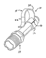
- FIG. 1A is a perspective view of a first embodiment of a finger retention clip according to the present application.
- FIGS. 1B-1D are orthographic views of the finger retention clip of FIG. 1A .
- FIG. 2A is a perspective view of the finger retention clip of FIGS. 1A-1D shown attached to a flashlight.
- FIGS. 2B-2D are orthographic views of the finger retention clip and flashlight of FIG. 2A .
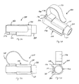
- FIG. 3A is a perspective view of an alternative embodiment of a finger retention clip according to the present application shown attached to a flashlight.
- FIGS. 3B-3D are orthographic views of the finger retention clip of FIG. 3A .
- FIGS. 4A and 4B are perspective views of the retaining member of the finger retention clip of FIGS. 3A-3D .
- FIGS. 4C-4F are orthographic views of the retaining member of FIGS. 4A and 4B .
- FIG. 5 is a perspective view a finger retention clip and flashlight according to the present application shown being worn by a user.
- the finger retention clips of the present application allow the user to hold and use the objects with one hand, while still being able to use that hand to perform other tasks, such as using tools, climbing ladders, using weapons, etc.
- the finger retention clips of the present application include large, open-loop retaining members that perform multiple functions, including: retaining the clip securely to the user's finger or fingers; allowing the user to store the finger retention clip on a belt or pocket; allowing the user to quickly get the finger retention clip onto his finger by simply inserting his finger or fingers through the clip member while the finger retention clip is being stored on a belt or pocket; and allowing the user to rotate the clip member about his finger or fingers to quickly move the object from the palm side of his hand to the back side of his hand, and vice versa.
- One important feature of the finger retention clips of the present application is that the clips are selectively tailored and configured to provide a safe and effective “tear-away” feature, so that the user is not harmed if the object is pulled away from the user's finger.
- finger retention clips of the present application are shown and described herein as being releasably attached to flashlights, the finger retention clips of the present application may be releasably attached to a wide variety of objects and tools.
- the finger retention clips of the present application are described herein as being retrofit onto existing flashlights, it will be appreciated that the finger retention clips of the present application may be easily made as integral components of the objects.
- a finger retention clip 10 according to a first embodiment of the present application is illustrated.
- Clip 10 includes a base member 12 and a retaining member 14 .
- Base member 12 and retaining member 14 are preferably made of the same semi-rigid material, such as plastic, nylon, or rubber; however, it will be appreciated that base member 12 and retaining member 14 may be made of different types of material, and that portions of base member 12 and retaining member 14 may also be made of various materials.
- base member 12 and/or retaining member 14 may include one or more moisture-resistant layers, surface treatments, coatings, various anti-slip features, decorative components, and/or defensive components.
- base member 12 includes a slot 16 that makes an open loop out of base member 12 .
- Slot 16 allows base member 12 to be stretched apart, so that base member 12 may be installed around an object, such as flashlight 18 .
- base member 12 is formed of a semi-rigid, resilient material, base member 12 fits snuggly around flashlight 18 , but may be quickly and easily released from flashlight 18 , if desired.
- a layer of adhesive or other bonding material may be applied between base member 12 and flashlight 18 .
- base member 12 may be attached to flashlight 18 with milled mounting screws, bolts, or other threaded or twist-lock fasteners.
- Retaining member 14 preferably includes a neck portion 20 that is attached to base member 12 and extends outward from base member 12 .
- Neck portion 20 transitions into a thinner tab portion 22 that curves back toward base member 12 .
- Neck portion 20 and tab portion 22 form a large open finger loop, preferably large enough for a user's finger to pass through.
- Tab portion 22 may curve back outward away from base member 12 to facilitate the placement of clip 10 onto a belt or into a pocket. Because retaining member 14 is formed of a semi-rigid, resilient material, retaining member 14 clamps against flashlight 18 and holds clip 10 securely against a belt or pocket.
- Retaining member 14 may be used to releasably attach clip 10 to other objects, such as straps, ladders, tools, backpacks, etc.
- Tab portion 22 may be configured to be in contact with flashlight 18 , i.e., pressing against flashlight 18 with a tailored preload, or merely in close proximity. It will be appreciated that in some applications it will be desirable that tab portion 22 be wider than neck portion 20 .
- Clip 10 includes a unique tear-away feature, in that clip 10 will break or otherwise release from the user's finger without harming the user in the event clip 10 (or the object to which clip 10 is attached) becomes snagged on an obstruction, or is otherwise pulled or twisted away.
- the user may be a law enforcement officer and flashlight 18 may get pulled away in a scuffle with a perpetrator; or the user may be a hunter and flashlight 18 may get snagged on a ladder or a tree branch.
- This tear-away feature can be accomplished in a variety of ways.
- Clip 10 can be custom tailored to ensure that clip 10 yields, or otherwise releases from the user's finger in a predesigned fashion in response to certain tension or torsion forces.
- base member 12 can break, base member 12 can twist off of the object, neck portion 20 can break, tab portion 22 can break, the connection between neck portion 20 and base member 12 can break, and retaining member 14 can twist off of the user's finger.
- clip 10 may include notches and other structural features that selectively provide stress concentrations, which facilitate the yielding of clip 10 when subjected to certain forces.
- Clip 100 is a two-piece assembly having a base member 120 and a retaining member 140 .
- Base member 120 and retaining member 140 are preferably made of the same semi-rigid material, such as plastic, nylon, or rubber; however, it will be appreciated that base member 120 and retaining member 140 may be made of different types of material, and that portions of base member 120 and retaining member 140 may also be made of various materials.
- base member 120 and/or retaining member 140 may include one or more moisture-resistant layers, surface treatments, coatings, various anti-slip features, decorative components, and/or defensive components.
- base member 120 includes a rigid tubular connector 170 and at least one elongated receiver channel 160 .
- Base member 120 is configured to allow base member 120 to be installed around an object, such as a flashlight 180 .
- base member 120 is formed of a semi-rigid, resilient material
- tubular member 170 fits snuggly around flashlight 180 , but may be quickly and easily released from flashlight 180 , if desired.
- Tubular connector 170 may also be made from a non-rigid material, including resilient tubular material (such as nylon, silicone, rubber, and/or plastic), adjustable straps, hook and loop tape, and various combinations of such types of materials.
- base member 120 may be attached to flashlight 180 with milled mounting screws, bolts, or other threaded or twist-lock fasteners.
- Retaining member 140 preferably includes an elongated slider tab 150 , a stop tab 152 , a neck portion 154 located between slider tab 150 and stop tab 152 , and a loop member 156 .
- Neck portion 154 forms a transition between slider tab 152 and loop member 156 .
- Loop member 156 forms a large open loop, preferably large enough for a user's finger to pass through. Loop member 156 may curve back outward away from slider tab 150 to facilitate the placement of clip 100 onto a belt or into a pocket. Because loop member 156 is formed of a semi-rigid, resilient material, loop member 156 is biased toward flashlight 180 and holds clip 100 securely against a belt or pocket.
- loop member 156 may be used to releasably attach clip 100 to other objects, such as ladders, tools, backpacks, etc. Loop member 156 may be configured to be in contact with flashlight 180 , i.e., pressing against flashlight 180 with a tailored preload, or merely in close proximity.
- Receiver channel 160 is preferably shaped and dimensioned to matingly receive slider tab 150 .
- Slider tab 150 and receiver channel 160 are also shaped and dimensioned to be received by conventional weapon mounting platforms and tactical gun rails, such as PicatinnyTM rails. This allows flashlight 180 to be quickly and easily interchanged between hand-held use and use with a weapon having conventional attachment rails.
- retaining member 140 may be used with any device, such as flashlights, scopes, range finders, laser pointers, couplings, and/or adapters, having conventional attachment rails. By attaching retaining member 140 to these devices, the user can use these devices in a hand-held manner and also store them for quick and easy removal from a belt or pocket.
- Slider tab 150 may have the same cross-sectional shape as receiver channel 160 .
- Receiver channel 160 may include mounting apertures through which threaded mounting screws or unthreaded fasteners may pass for securing slider tab 150 to receiver channel 160 and/or for securing receiver channel 160 to a tactical rail system.
- tubular connector 170 may include multiple receiver channels 160 . This also allows tubular connector 170 and flashlight 180 to be mounted to a tactical rail system via one receiver channel 160 , while being coupled to slider tab 150 via another receiver channel 160 .
- clip 100 includes a unique tear-away feature, in that clip 100 will break or otherwise release from the user's finger without harming the user in the event clip 100 (or the object to which clip 100 is attached) becomes snagged on an obstruction, or is otherwise pulled or twisted away.
- the user may be a law enforcement officer and flashlight 180 may get pulled away in a scuffle with a perpetrator; or the user may be a hunter and flashlight 180 may get snagged on a ladder or a tree branch.
- This tear-away feature can be accomplished in a variety of ways.
- Clip 100 can be custom tailored to ensure that clip 100 yields, or otherwise releases from the user's finger in a predesigned fashion in response to certain tension or torsion forces. For example: slider tab 150 can break, slider tab 150 release from receiver channel 160 , neck portion 154 can break, loop member 156 , and loop member 156 can twist off of the user's finger.
- retaining member 14 and loop member 156 have been shown as forming only a single loop shaped and dimensioned to fit a single finger, it should be understood that retaining member 14 and loop member 156 may be shaped to accommodate two or more fingers.
- base members 12 and 120 have been shown having circular cross-sections, it should be understood that base members 12 and 120 may have any desirable cross-sectional shape.
- finger retention clip 10 and flashlight 18 is preferably stored or stowed in a pocket, in a pouch, on a belt, on a weapon sling, on a ladder, or anywhere else in which the user can reach clip 10 with his hand.
- clip 100 functions in a similar fashion as clip 10 .
- a pocket application will be used. The user inserts tab portion 22 into the pocket. Because retaining member 14 forms a relatively large loop, retaining member 14 extends out from the pocket. This allows the user to engage clip 10 quickly and easily by simply moving his hand toward clip 10 and allowing one or more of his fingers to slip onto the loop formed by retaining member 14 .
- Clip 10 and flashlight 18 may be returned to the stowed position by hooking retaining member 14 inside the pocket and simply withdrawing his finger from retaining member 14 .
- Clip 10 is particularly useful for flashlights having control switches on the base end, as the user can easily access such switches with his thumb, while using clip 10 .
- Clip 10 allows the user to loosen his grasp on flashlight 18 to perform other tasks with that hand, such as using other tools, climbing a ladder, operating a phone, or working with other objects, without dropping flashlight 18 .
- retaining member 14 forms a relatively large loop, the user can quickly and easily rotate clip 10 and flashlight 18 about his finger until flashlight 18 is adjacent the back side of the user's hand. This position gives the user unobstructed use of his hand, without having to put flashlight 18 down.
- Retaining member 14 performs other functions, as well. Because retaining member 14 stands out from base member 12 , retaining member 14 prevents flashlight from rolling away when flashlight 18 is placed on an inclined surface. In addition, because retaining member 14 is relatively wide, retaining member 14 allows clip 10 and flashlight 18 to stand on edge, thereby allowing the user to directly aim the light at a desired location.
Landscapes
- Engineering & Computer Science (AREA)
- General Engineering & Computer Science (AREA)
- Clamps And Clips (AREA)
Abstract
A finger retention clip for retaining an object about a user's finger includes a tubular base member adapted for attachment to the object and a resilient retaining member attached to the base member, the retaining member forming an open finger loop and being sized and shaped to conform to the user's finger, wherein the retaining member is configured, such that the retaining member releases from the user's finger in response to a selected force.
Description
The present application relates generally to retention clips for holding small devices.
There are many different types of lanyards and retentions clips for holding small objects, such as keys, tools, writing implements, and the like. These retention devices usually have straps and/or clips for retaining and storing the objects in close proximity to the user, so that the user can quickly and easily grab the object, use it, and return it to its storage position.
Although great strides have been made in the area of retention clips for holding small devices, many shortcomings remain.
The novel features believed characteristic of the embodiments of the present application are set forth in the appended claims. However, the embodiments themselves, as well as a preferred mode of use, and further objectives and advantages thereof, will best be understood by reference to the following detailed description when read in conjunction with the accompanying drawings, wherein:
While the assembly and method of the present application is susceptible to various modifications and alternative forms, specific embodiments thereof have been shown by way of example in the drawings and are herein described in detail. It should be understood, however, that the description herein of specific embodiments is not intended to limit the present application to the particular embodiment disclosed, but on the contrary, the intention is to cover all modifications, equivalents, alternatives, and combinations thereof, falling within the spirit and scope of the present application as defined by the appended claims.
The finger retention clips of the present application allow the user to hold and use the objects with one hand, while still being able to use that hand to perform other tasks, such as using tools, climbing ladders, using weapons, etc. The finger retention clips of the present application include large, open-loop retaining members that perform multiple functions, including: retaining the clip securely to the user's finger or fingers; allowing the user to store the finger retention clip on a belt or pocket; allowing the user to quickly get the finger retention clip onto his finger by simply inserting his finger or fingers through the clip member while the finger retention clip is being stored on a belt or pocket; and allowing the user to rotate the clip member about his finger or fingers to quickly move the object from the palm side of his hand to the back side of his hand, and vice versa. One important feature of the finger retention clips of the present application is that the clips are selectively tailored and configured to provide a safe and effective “tear-away” feature, so that the user is not harmed if the object is pulled away from the user's finger.
It will be appreciated that while the finger retention clips of the present application are shown and described herein as being releasably attached to flashlights, the finger retention clips of the present application may be releasably attached to a wide variety of objects and tools. In addition, while the finger retention clips of the present application are described herein as being retrofit onto existing flashlights, it will be appreciated that the finger retention clips of the present application may be easily made as integral components of the objects.
Referring to FIGS. 1A-1D and 2A-2D in the drawings, a finger retention clip 10 according to a first embodiment of the present application is illustrated. Clip 10 includes a base member 12 and a retaining member 14. Base member 12 and retaining member 14 are preferably made of the same semi-rigid material, such as plastic, nylon, or rubber; however, it will be appreciated that base member 12 and retaining member 14 may be made of different types of material, and that portions of base member 12 and retaining member 14 may also be made of various materials. For example, base member 12 and/or retaining member 14 may include one or more moisture-resistant layers, surface treatments, coatings, various anti-slip features, decorative components, and/or defensive components.
As is shown, base member 12 includes a slot 16 that makes an open loop out of base member 12. Slot 16 allows base member 12 to be stretched apart, so that base member 12 may be installed around an object, such as flashlight 18. Because base member 12 is formed of a semi-rigid, resilient material, base member 12 fits snuggly around flashlight 18, but may be quickly and easily released from flashlight 18, if desired. In some embodiments, it may desirable for base member 12 to be permanently, or semi-permanently, affixed to flashlight 18. In such cases, a layer of adhesive or other bonding material may be applied between base member 12 and flashlight 18. In addition, base member 12 may be attached to flashlight 18 with milled mounting screws, bolts, or other threaded or twist-lock fasteners.
Retaining member 14 preferably includes a neck portion 20 that is attached to base member 12 and extends outward from base member 12. Neck portion 20 transitions into a thinner tab portion 22 that curves back toward base member 12. Neck portion 20 and tab portion 22 form a large open finger loop, preferably large enough for a user's finger to pass through. Tab portion 22 may curve back outward away from base member 12 to facilitate the placement of clip 10 onto a belt or into a pocket. Because retaining member 14 is formed of a semi-rigid, resilient material, retaining member 14 clamps against flashlight 18 and holds clip 10 securely against a belt or pocket. Retaining member 14 may be used to releasably attach clip 10 to other objects, such as straps, ladders, tools, backpacks, etc. Tab portion 22 may be configured to be in contact with flashlight 18, i.e., pressing against flashlight 18 with a tailored preload, or merely in close proximity. It will be appreciated that in some applications it will be desirable that tab portion 22 be wider than neck portion 20.
Referring now also to FIGS. 3A-3D and 4A-4F in the drawings, a finger retention clip 100 according to an alternative embodiment of the present application is illustrated. Clip 100 is a two-piece assembly having a base member 120 and a retaining member 140. Base member 120 and retaining member 140 are preferably made of the same semi-rigid material, such as plastic, nylon, or rubber; however, it will be appreciated that base member 120 and retaining member 140 may be made of different types of material, and that portions of base member 120 and retaining member 140 may also be made of various materials. For example, base member 120 and/or retaining member 140 may include one or more moisture-resistant layers, surface treatments, coatings, various anti-slip features, decorative components, and/or defensive components.
As is shown, base member 120 includes a rigid tubular connector 170 and at least one elongated receiver channel 160. Base member 120 is configured to allow base member 120 to be installed around an object, such as a flashlight 180. Because base member 120 is formed of a semi-rigid, resilient material, tubular member 170 fits snuggly around flashlight 180, but may be quickly and easily released from flashlight 180, if desired. Tubular connector 170 may also be made from a non-rigid material, including resilient tubular material (such as nylon, silicone, rubber, and/or plastic), adjustable straps, hook and loop tape, and various combinations of such types of materials. In some embodiments, it may desirable for base member 120 to be permanently, or semi-permanently, affixed to flashlight 180. In such cases, a layer of adhesive or other bonding material may be applied between tubular member 170 and flashlight 180. In addition, base member 120 may be attached to flashlight 180 with milled mounting screws, bolts, or other threaded or twist-lock fasteners.
Retaining member 140 preferably includes an elongated slider tab 150, a stop tab 152, a neck portion 154 located between slider tab 150 and stop tab 152, and a loop member 156. Neck portion 154 forms a transition between slider tab 152 and loop member 156. Loop member 156 forms a large open loop, preferably large enough for a user's finger to pass through. Loop member 156 may curve back outward away from slider tab 150 to facilitate the placement of clip 100 onto a belt or into a pocket. Because loop member 156 is formed of a semi-rigid, resilient material, loop member 156 is biased toward flashlight 180 and holds clip 100 securely against a belt or pocket. It will be appreciated that loop member 156 may be used to releasably attach clip 100 to other objects, such as ladders, tools, backpacks, etc. Loop member 156 may be configured to be in contact with flashlight 180, i.e., pressing against flashlight 180 with a tailored preload, or merely in close proximity.
As with clip 10, clip 100 includes a unique tear-away feature, in that clip 100 will break or otherwise release from the user's finger without harming the user in the event clip 100 (or the object to which clip 100 is attached) becomes snagged on an obstruction, or is otherwise pulled or twisted away. For example, the user may be a law enforcement officer and flashlight 180 may get pulled away in a scuffle with a perpetrator; or the user may be a hunter and flashlight 180 may get snagged on a ladder or a tree branch. This tear-away feature can be accomplished in a variety of ways. Clip 100 can be custom tailored to ensure that clip 100 yields, or otherwise releases from the user's finger in a predesigned fashion in response to certain tension or torsion forces. For example: slider tab 150 can break, slider tab 150 release from receiver channel 160, neck portion 154 can break, loop member 156, and loop member 156 can twist off of the user's finger.
Although retaining member 14 and loop member 156 have been shown as forming only a single loop shaped and dimensioned to fit a single finger, it should be understood that retaining member 14 and loop member 156 may be shaped to accommodate two or more fingers. In addition, although base members 12 and 120 have been shown having circular cross-sections, it should be understood that base members 12 and 120 may have any desirable cross-sectional shape.
In operation, finger retention clip 10 and flashlight 18 is preferably stored or stowed in a pocket, in a pouch, on a belt, on a weapon sling, on a ladder, or anywhere else in which the user can reach clip 10 with his hand. It will be appreciated that's clip 100 functions in a similar fashion as clip 10. For purposes of this description, a pocket application will be used. The user inserts tab portion 22 into the pocket. Because retaining member 14 forms a relatively large loop, retaining member 14 extends out from the pocket. This allows the user to engage clip 10 quickly and easily by simply moving his hand toward clip 10 and allowing one or more of his fingers to slip onto the loop formed by retaining member 14. Then, the user can pull clip 10 and flashlight 18 out of the pocket, leaving flashlight 18 adjacent to the palm of the user's hand, as shown in FIG. 5 . Clip 10 and flashlight 18 may be returned to the stowed position by hooking retaining member 14 inside the pocket and simply withdrawing his finger from retaining member 14.
Retaining member 14 performs other functions, as well. Because retaining member 14 stands out from base member 12, retaining member 14 prevents flashlight from rolling away when flashlight 18 is placed on an inclined surface. In addition, because retaining member 14 is relatively wide, retaining member 14 allows clip 10 and flashlight 18 to stand on edge, thereby allowing the user to directly aim the light at a desired location.
It is apparent that a system with significant advantages has been described and illustrated. The particular embodiments disclosed above are illustrative only, as the embodiments may be modified and practiced in different but equivalent manners apparent to those skilled in the art having the benefit of the teachings herein. It is therefore evident that the particular embodiments disclosed above may be altered or modified, and all such variations are considered within the scope and spirit of the application. Accordingly, the protection sought herein is as set forth in the description. Although the present embodiments are shown above, they are not limited to just these embodiments, but are amenable to various changes and modifications without departing from the spirit thereof.
Claims (10)
1. A finger retention clip for retaining an object about a user's finger, comprising:
a base member adapted for attachment to the object; and
a resilient retaining member attached to the base member, the retaining member forming an open finger loop and being sized and shaped to conform to the user's finger;
wherein the retaining member has a first width, and a second width narrower than the first width;
wherein the retaining member includes a structural feature that selectively provides a stress concentration, such that the retaining member releases from the user's finger in response to a selected force by breaking of the retaining member.
2. The finger retention clip according to claim 1 , wherein the base member is resilient and comprises:
a longitudinal slot adapted to allow the base member to spread apart to facilitate attachment of the base member to the object;
wherein the base member is tubular.
3. The finger retention clip according to claim 1 , wherein the open finger loop is configured to accommodate multiple fingers.
4. The finger retention clip according to claim 1 , wherein the object is a flashlight.
5. The finger retention clip according to claim 1 , wherein the retaining member comprises:
a neck portion having the first width, the neck portion attached to the base member; and
an upturned tab portion having the second width.
6. The finger retention clip according to claim 5 , wherein the tab portion and the neck portion are of different widths.
7. The finger retention clip according to claim 1 , wherein the structural feature is a pair of notches separating the first width of the retaining member from the second width of the retaining member.
8. The finger retention clip according to claim 1 , wherein the base member is releasable from the object.
9. The finger retention clip according to claim 1 , wherein the base member is selectively tailored to release from the object in response to a selected force.
10. The finger retention clip according to claim 1 , wherein the base member and the retaining member are made from different materials.
Priority Applications (1)
| Application Number | Priority Date | Filing Date | Title |
|---|---|---|---|
| US15/662,397 US10188198B1 (en) | 2017-07-28 | 2017-07-28 | Finger retention clip |
Applications Claiming Priority (1)
| Application Number | Priority Date | Filing Date | Title |
|---|---|---|---|
| US15/662,397 US10188198B1 (en) | 2017-07-28 | 2017-07-28 | Finger retention clip |
Publications (1)
| Publication Number | Publication Date |
|---|---|
| US10188198B1 true US10188198B1 (en) | 2019-01-29 |
Family
ID=65032766
Family Applications (1)
| Application Number | Title | Priority Date | Filing Date |
|---|---|---|---|
| US15/662,397 Active US10188198B1 (en) | 2017-07-28 | 2017-07-28 | Finger retention clip |
Country Status (1)
| Country | Link |
|---|---|
| US (1) | US10188198B1 (en) |
Cited By (1)
| Publication number | Priority date | Publication date | Assignee | Title |
|---|---|---|---|---|
| US20240328611A1 (en) * | 2023-04-02 | 2024-10-03 | Andrew Frazier | Tactical flashlight accessories |
Citations (14)
| Publication number | Priority date | Publication date | Assignee | Title |
|---|---|---|---|---|
| US503011A (en) * | 1893-08-08 | Pen or pencil holder | ||
| US1462714A (en) * | 1922-08-05 | 1923-07-24 | Thomas E Marchand | Pencil-holding clip |
| US2072851A (en) * | 1935-07-25 | 1937-03-09 | Bailey Wilson | Cigarette holder |
| US2084343A (en) * | 1936-04-28 | 1937-06-22 | Jefferis Alice | Cigarette holder |
| US3263444A (en) * | 1963-07-18 | 1966-08-02 | Croce Robert N Di | Safety finger ring having separable parts |
| US3596964A (en) * | 1968-12-19 | 1971-08-03 | Joseph R Zazzara | Writing implement holder |
| US3666372A (en) * | 1970-01-14 | 1972-05-30 | William J Lipkowski | Manual coupler for writing instruments |
| US4084692A (en) * | 1974-09-03 | 1978-04-18 | Ethicon, Inc. | Dispenser for surgical threads |
| US5732862A (en) * | 1997-02-14 | 1998-03-31 | Bull; Charles L. | Material holding apparatus with integrated finger mount |
| US6082997A (en) * | 1998-01-12 | 2000-07-04 | Prescott; Phyllis Matuska | Dental prophylaxis paste holder |
| US6164965A (en) * | 1999-12-09 | 2000-12-26 | Nuview Technologies, Inc. | Prophylaxis paste holder ring and method of manufacture |
| US6280189B1 (en) * | 1999-01-26 | 2001-08-28 | Ivoclar Vivadent Ag | Clip holder for dental material |
| US6905271B1 (en) * | 2002-11-26 | 2005-06-14 | Ronald J. Short | Finger-mounted marking device |
| US8196787B2 (en) * | 2007-07-30 | 2012-06-12 | Hewlett-Packard Development Company, L.P. | Hand mount |
-
2017
- 2017-07-28 US US15/662,397 patent/US10188198B1/en active Active
Patent Citations (14)
| Publication number | Priority date | Publication date | Assignee | Title |
|---|---|---|---|---|
| US503011A (en) * | 1893-08-08 | Pen or pencil holder | ||
| US1462714A (en) * | 1922-08-05 | 1923-07-24 | Thomas E Marchand | Pencil-holding clip |
| US2072851A (en) * | 1935-07-25 | 1937-03-09 | Bailey Wilson | Cigarette holder |
| US2084343A (en) * | 1936-04-28 | 1937-06-22 | Jefferis Alice | Cigarette holder |
| US3263444A (en) * | 1963-07-18 | 1966-08-02 | Croce Robert N Di | Safety finger ring having separable parts |
| US3596964A (en) * | 1968-12-19 | 1971-08-03 | Joseph R Zazzara | Writing implement holder |
| US3666372A (en) * | 1970-01-14 | 1972-05-30 | William J Lipkowski | Manual coupler for writing instruments |
| US4084692A (en) * | 1974-09-03 | 1978-04-18 | Ethicon, Inc. | Dispenser for surgical threads |
| US5732862A (en) * | 1997-02-14 | 1998-03-31 | Bull; Charles L. | Material holding apparatus with integrated finger mount |
| US6082997A (en) * | 1998-01-12 | 2000-07-04 | Prescott; Phyllis Matuska | Dental prophylaxis paste holder |
| US6280189B1 (en) * | 1999-01-26 | 2001-08-28 | Ivoclar Vivadent Ag | Clip holder for dental material |
| US6164965A (en) * | 1999-12-09 | 2000-12-26 | Nuview Technologies, Inc. | Prophylaxis paste holder ring and method of manufacture |
| US6905271B1 (en) * | 2002-11-26 | 2005-06-14 | Ronald J. Short | Finger-mounted marking device |
| US8196787B2 (en) * | 2007-07-30 | 2012-06-12 | Hewlett-Packard Development Company, L.P. | Hand mount |
Cited By (2)
| Publication number | Priority date | Publication date | Assignee | Title |
|---|---|---|---|---|
| US20240328611A1 (en) * | 2023-04-02 | 2024-10-03 | Andrew Frazier | Tactical flashlight accessories |
| US12359798B2 (en) * | 2023-04-02 | 2025-07-15 | Andrew Frazier | Tactical flashlight accessories |
Similar Documents
| Publication | Publication Date | Title |
|---|---|---|
| US8545041B2 (en) | Mounting clip | |
| US10119655B2 (en) | Item holder | |
| US8720754B2 (en) | Locking and quick release mechanism for handgun holsters | |
| US8650794B2 (en) | Firearm fastener | |
| US20080018122A1 (en) | Rifle Sling and Method of Use Thereof | |
| US8205374B2 (en) | Pistol carrier | |
| US7025238B2 (en) | Quick release implement holder | |
| US7798137B2 (en) | Compound archery bow with an adaptor device for carrying a compound archery bow | |
| US20080121670A1 (en) | Weapon Holster System | |
| US20060282939A1 (en) | Mounting system for accessories on a safety helmet | |
| US20110174847A1 (en) | Handgun Holster | |
| US20140196349A1 (en) | Selectively Releasable Flashlight Attachment Device for Handgun | |
| US9328992B1 (en) | Method and apparatus for gun stabilizer | |
| US20160265873A1 (en) | Gun Sling with Tourniquet and Methods of Making the Same | |
| US7331872B1 (en) | Baton scabbard belt plate | |
| US20150122855A1 (en) | Carrying case for police or military baton | |
| US20090084697A1 (en) | Retractable carrying device for an optical device | |
| US20040020524A1 (en) | Walking cane retainer | |
| US6270231B1 (en) | Flashlight holder | |
| CA203939S (en) | Attachment clip with separate retainer element for attachment to and use on tactical belts, holsters and the like | |
| US10495407B1 (en) | Panel attachable to a firearm | |
| US9689641B2 (en) | Hands free carrier system | |
| US10188198B1 (en) | Finger retention clip | |
| US20120081913A1 (en) | Barrel mounted clamp having integrated accessory holder | |
| US10775130B1 (en) | Holster for assault rifle |
Legal Events
| Date | Code | Title | Description |
|---|---|---|---|
| STCF | Information on status: patent grant |
Free format text: PATENTED CASE |
|
| MAFP | Maintenance fee payment |
Free format text: PAYMENT OF MAINTENANCE FEE, 4TH YEAR, MICRO ENTITY (ORIGINAL EVENT CODE: M3551); ENTITY STATUS OF PATENT OWNER: MICROENTITY Year of fee payment: 4 |