US10179357B2 - Bending apparatus and bending method for a plate-shaped metal workpiece - Google Patents
Bending apparatus and bending method for a plate-shaped metal workpiece Download PDFInfo
- Publication number
- US10179357B2 US10179357B2 US15/053,953 US201615053953A US10179357B2 US 10179357 B2 US10179357 B2 US 10179357B2 US 201615053953 A US201615053953 A US 201615053953A US 10179357 B2 US10179357 B2 US 10179357B2
- Authority
- US
- United States
- Prior art keywords
- workpiece
- bending apparatus
- plate
- bending
- suction
- Prior art date
- Legal status (The legal status is an assumption and is not a legal conclusion. Google has not performed a legal analysis and makes no representation as to the accuracy of the status listed.)
- Active
Links
- 238000005452 bending Methods 0.000 title claims abstract description 107
- 239000002184 metal Substances 0.000 title claims abstract description 54
- 238000000034 method Methods 0.000 title description 22
- 230000002093 peripheral effect Effects 0.000 claims 3
- 230000007423 decrease Effects 0.000 claims 2
- 230000003247 decreasing effect Effects 0.000 claims 1
- 230000008602 contraction Effects 0.000 abstract description 26
- 239000011111 cardboard Substances 0.000 description 6
- 210000000078 claw Anatomy 0.000 description 6
- 229910000737 Duralumin Inorganic materials 0.000 description 4
- 238000013001 point bending Methods 0.000 description 4
- 238000004519 manufacturing process Methods 0.000 description 3
- 238000005259 measurement Methods 0.000 description 3
- 239000004033 plastic Substances 0.000 description 3
- 239000000945 filler Substances 0.000 description 2
- 230000008878 coupling Effects 0.000 description 1
- 238000010168 coupling process Methods 0.000 description 1
- 238000005859 coupling reaction Methods 0.000 description 1
- 230000006866 deterioration Effects 0.000 description 1
- 238000005516 engineering process Methods 0.000 description 1
- 238000007689 inspection Methods 0.000 description 1
- 239000000463 material Substances 0.000 description 1
- 230000007246 mechanism Effects 0.000 description 1
- 239000007769 metal material Substances 0.000 description 1
- 238000012986 modification Methods 0.000 description 1
- 230000004048 modification Effects 0.000 description 1
- 238000003825 pressing Methods 0.000 description 1
- 230000009467 reduction Effects 0.000 description 1
Images


Classifications
-
- B—PERFORMING OPERATIONS; TRANSPORTING
- B21—MECHANICAL METAL-WORKING WITHOUT ESSENTIALLY REMOVING MATERIAL; PUNCHING METAL
- B21D—WORKING OR PROCESSING OF SHEET METAL OR METAL TUBES, RODS OR PROFILES WITHOUT ESSENTIALLY REMOVING MATERIAL; PUNCHING METAL
- B21D11/00—Bending not restricted to forms of material mentioned in only one of groups B21D5/00, B21D7/00, B21D9/00; Bending not provided for in groups B21D5/00 - B21D9/00; Twisting
- B21D11/20—Bending sheet metal, not otherwise provided for
-
- B—PERFORMING OPERATIONS; TRANSPORTING
- B21—MECHANICAL METAL-WORKING WITHOUT ESSENTIALLY REMOVING MATERIAL; PUNCHING METAL
- B21D—WORKING OR PROCESSING OF SHEET METAL OR METAL TUBES, RODS OR PROFILES WITHOUT ESSENTIALLY REMOVING MATERIAL; PUNCHING METAL
- B21D11/00—Bending not restricted to forms of material mentioned in only one of groups B21D5/00, B21D7/00, B21D9/00; Bending not provided for in groups B21D5/00 - B21D9/00; Twisting
- B21D11/02—Bending by stretching or pulling over a die
-
- B—PERFORMING OPERATIONS; TRANSPORTING
- B21—MECHANICAL METAL-WORKING WITHOUT ESSENTIALLY REMOVING MATERIAL; PUNCHING METAL
- B21D—WORKING OR PROCESSING OF SHEET METAL OR METAL TUBES, RODS OR PROFILES WITHOUT ESSENTIALLY REMOVING MATERIAL; PUNCHING METAL
- B21D22/00—Shaping without cutting, by stamping, spinning, or deep-drawing
- B21D22/02—Stamping using rigid devices or tools
- B21D22/06—Stamping using rigid devices or tools having relatively-movable die parts
-
- B—PERFORMING OPERATIONS; TRANSPORTING
- B21—MECHANICAL METAL-WORKING WITHOUT ESSENTIALLY REMOVING MATERIAL; PUNCHING METAL
- B21D—WORKING OR PROCESSING OF SHEET METAL OR METAL TUBES, RODS OR PROFILES WITHOUT ESSENTIALLY REMOVING MATERIAL; PUNCHING METAL
- B21D25/00—Working sheet metal of limited length by stretching, e.g. for straightening
- B21D25/02—Working sheet metal of limited length by stretching, e.g. for straightening by pulling over a die
-
- B—PERFORMING OPERATIONS; TRANSPORTING
- B21—MECHANICAL METAL-WORKING WITHOUT ESSENTIALLY REMOVING MATERIAL; PUNCHING METAL
- B21D—WORKING OR PROCESSING OF SHEET METAL OR METAL TUBES, RODS OR PROFILES WITHOUT ESSENTIALLY REMOVING MATERIAL; PUNCHING METAL
- B21D37/00—Tools as parts of machines covered by this subclass
- B21D37/02—Die constructions enabling assembly of the die parts in different ways
-
- B—PERFORMING OPERATIONS; TRANSPORTING
- B21—MECHANICAL METAL-WORKING WITHOUT ESSENTIALLY REMOVING MATERIAL; PUNCHING METAL
- B21D—WORKING OR PROCESSING OF SHEET METAL OR METAL TUBES, RODS OR PROFILES WITHOUT ESSENTIALLY REMOVING MATERIAL; PUNCHING METAL
- B21D53/00—Making other particular articles
- B21D53/92—Making other particular articles other parts for aircraft
Definitions
- the present invention relates to a technology of bending a metal plate, such as a plate-shaped metal workpiece (plate-shaped workpiece) used as an outer-plate (or a skin) of an aircraft, into an arc shape (cylindrical shape) at a predetermined curvature.
- a metal plate such as a plate-shaped metal workpiece (plate-shaped workpiece) used as an outer-plate (or a skin) of an aircraft, into an arc shape (cylindrical shape) at a predetermined curvature.
- an outer shell of an aircraft (having a substantially cylindrical shape in horizontal cross-section) is obtained by coupling together several outer-plates (skins) of the aircraft each bent at a predetermined curvature (for example, each having approximately a size of a thickness of from 2 mm to 10 mm ⁇ a width of 2.5 m ⁇ a length of from 6 m to 10 m) so as to be formed into a cylindrical shape.
- outer-plate (or skin) workpieces (plate-shaped workpieces) each cut into a predetermined size are subjected to tip forming by a large-sized press brake (forming machine) one by one (three-point bending (see FIG.
- each of the outer-plate workpieces is formed into a single contour having a curvature radius R of approximately 3,000 mm. Then, the plurality of outer-plate workpieces (plate-shaped workpieces) each formed to have the predetermined curvature are coupled together, thereby obtaining the outer shell of the aircraft.
- a plurality of pocket grooves (dents) are formed on an inner side (side to be punched) of the outer-plate of the aircraft, which is to be subjected to cylindrical bending.
- shape patterns of the pocket grooves (dents) see reference symbol 3 A in FIG. 1B , and FIG. 8 ).
- a board such as a cardboard (filler having a hardness nearly equal to a hardness of a plate)
- a board which conforms to a size and a shape of each of the pocket grooves, is placed in advance (embedded or fitted) in each of the pocket grooves (for example, see Japanese Patent Application Laid-open No. 2012-213792 and Japanese Patent Application Laid-open No. 2011-194426), and forming is performed under a state in which concaves and convexes are eliminated (a thickness of an entire region of the outer-plate workpiece is equalized).
- a product formed into a uniform contour product bent into a cylindrical shape with a predetermined curvature
- the outer-plate workpiece (plate-shaped workpiece) of the aircraft is a significantly large component having a width dimension of approximately 2.5 m and a length dimension (longitudinal dimension) of approximately from 6 m to 10 m, despite of a small thickness of approximately from 2 mm to 10 mm. Therefore, the outer-plate workpiece deflects due to a self-weight after forming. Accordingly, when the contour is measured in the deflecting state, in actuality, it is difficult to conduct with good accuracy an inspection of whether or not the predetermined curvature is obtained, and a skill is required.
- the outer-plate (or skin) has been formed by the tip forming method using the press brake (forming machine). Accordingly, in order to receive the outer-plate workpiece having the length dimension (longitudinal dimension) of approximately from 6 m to 10 m, a large-sized press brake having a frontage (column interval) of 10 m or more has been needed.
- a slide (punch) of the press brake deflects, and hence has an immense size in order to ensure rigidity (to suppress longitudinal deflection), which leads to increase of mass and increase of operation energy.
- a long period of time is needed to store the operation energy, and a long operation cycle is needed.
- production efficiency of the press brake is low.
- Adoption of a three-point press forming method employing the tip forming method when bending the outer-plate of the aircraft into a cylindrical shape is considered as a cause of the following: work that has hitherto required a long period of working hours (work of embedding cardboards into the pocket grooves (dents) and work of forming the outer-plate in while minutely adjusting thicknesses of the cardboards); and the press brake (forming machine) having an immense size and a wide frontage for receiving a large workpiece.
- a bending apparatus for a plate-shaped metal workpiece including:
- a suction device configured to suck a surface of a plate-shaped metal workpiece in a removable manner
- each of the plurality of expansion and contraction devices being capable of expanding and contracting a length ranging from a proximal end thereof to the suction device;
- the bending apparatus being configured to form the plate-shaped metal workpiece under bending deformation by expanding and contracting the plurality of expansion and contraction devices under a state in which the suction device sucks the surface of the plate-shaped metal workpiece.
- the proximal end may be pivotable with respect to the apparatus base.
- the bending apparatus for a plate-shaped metal workpiece may further include a clamping device configured to clamp an end portion of the plate-shaped metal workpiece in a thickness direction of the plate-shaped metal workpiece in a releasable manner, and the plate-shaped metal workpiece may be formed under bending deformation in such a manner that the clamping device is pivoted with respect to the apparatus base while clamping the end portion of the plate-shaped metal workpiece in the thickness direction.
- the clamping device may be movable in a width direction of the plate-shaped metal workpiece.
- expansion and contraction amounts of the plurality of expansion and contraction devices may be controllable.
- the bending apparatus may form the plate-shaped metal workpiece under bending deformation by expanding or contracting the plurality of expansion and contraction devices in a direction opposite to the same direction in sequential order from an innermost expansion and contraction device toward an outermost expansion and contraction device.
- a bending method for a plate-shaped metal workpiece including, by using a bending apparatus for a plate-shaped metal workpiece including:
- a suction device configured to suck a surface of a plate-shaped metal workpiece in a removable manner
- each of the plurality of expansion and contraction devices being capable of expanding and contracting a length ranging from a proximal end thereof to the suction device;
- the bending method for a plate-shaped metal workpiece further includes, after forming the plate-shaped metal workpiece under bending deformation by expanding or contracting the plurality of expansion and contraction devices in the same direction, forming the plate-shaped metal workpiece under bending deformation by expanding or contracting the plurality of expansion and contraction devices in a direction opposite to the same direction in sequential order from an innermost expansion and contraction device toward an outermost expansion and contraction device.
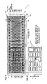
- FIG. 1A is a plan view (top view) of a bending apparatus for a plate-shaped metal workpiece according to an embodiment of the present invention.
- FIG. 1B is a partial plan view (top view) of a plate-shaped metal workpiece to be formed by the bending apparatus for a plate-shaped metal workpiece.
- FIG. 1C to FIG. 1E are side views of the bending apparatus for a plate-shaped metal workpiece when viewed from a width direction of the bending apparatus.
- FIG. 2A to FIG. 2F are side views for respectively illustrating Step 1 to Step 6 of forming steps of the bending apparatus (method) for a plate-shaped metal workpiece according to the embodiment of the present invention.
- FIG. 3A to FIG. 3E are side views for illustrating Step 7 to Step 11 of the forming steps of the bending apparatus (method) for a plate-shaped metal workpiece according to the embodiment of the present invention.
- FIG. 4A is a side view for illustrating a state in which pivotal movement (rocking angles) of servo screw jacks is controlled by servomotors with respect to a bed of the bending apparatus for a plate-shaped metal workpiece according to the embodiment of the present invention.
- FIG. 4B is a side view for illustrating a state in which the pivotal movement (rocking angles) of the servo screw jacks is automatically controlled by springs with respect to the bed.
- FIG. 5A is an enlarged side view for illustrating a configuration example of one of bender-cum-clamp members of the bending apparatus for a plate-shaped metal workpiece according to the embodiment of the present invention.
- FIG. 5B is a partial plan view (top view) of the one of bender-cum-clamp members.
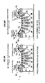
- FIG. 6A is a side view for illustrating a forming method in a case of simultaneously bending both ends of the plate-shaped metal workpiece at a predetermined curvature by the servo screw jacks and the bender-cum-clamp members of the bending apparatus for a plate-shaped metal workpiece according to the embodiment of the present invention.
- FIG. 6B is a side view for illustrating a forming method in a case of bending one end of the plate-shaped metal workpiece at a predetermined curvature.
- FIG. 7A is a view of a related-art press brake when viewed from a feeding direction (length direction) of a plate-shaped metal workpiece (view for illustrating a wide frontage of the press brake).
- FIG. 7B is a side view of FIG. 7A .
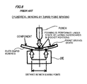
- FIG. 8 is a side view for illustrating a related-art cylindrical bending method employing three-point bending.
- the present invention has been made in view of the above-mentioned circumstances, and has an object to provide a bending apparatus and a bending method for a plate-shaped metal workpiece, which are capable of forming (bending into a cylindrical shape) a plate-shaped metal workpiece for an outer-plate (or a skin) of an aircraft and the like at a predetermined curvature efficiently with high accuracy and a relatively simple and low-cost configuration.
- the inventors of the present invention have focused on the fact that a plurality of pocket grooves (dents) having various shapes are formed in an inner surface (on a side of a center of a curvature radius) of an outer-plate (or a skin) of an aircraft to be formed into a cylindrical shape, but an outer surface (opposite surface) of the outer-plate is flat and has no pocket.
- the inventors of the present invention have created a method of bending an outer-plate workpiece (plate-shaped workpiece) into a cylindrical shape (at a predetermined curvature) by sucking and pulling the outer surface (on a side opposite to the center of the curvature radius) of the outer-plate of the aircraft to be formed into a cylindrical shape, thereby forcibly deforming the outer-plate workpiece (plate-shaped workpiece) through the pulling.
- the suction is performed using a suction pad (such as vacuum suction and magnetic attraction), and a position of the suction pad in a height direction (position thereof in an up-and-down direction in FIG. 2A to FIG. 2F ) can be controlled by a servo screw jack (actuator capable of performing position control) or the like.
- a suction pad such as vacuum suction and magnetic attraction
- a position of the suction pad in a height direction position thereof in an up-and-down direction in FIG. 2A to FIG. 2F
- a servo screw jack actuator capable of performing position control
- a plurality of servo screw jacks 20 A to 20 G each having a suction pad 10 (suction cup in a case of vacuum suction) mounted to a distal end thereof are mounted to a bed 2 through pivots 21 a to 21 g.
- the suction pad 10 corresponds to an example of a suction device according to the present invention
- the servo screw jacks 20 A to 20 G correspond to an example of expansion and contraction devices according to the present invention.
- the bed 2 corresponds to an apparatus base according to the present invention.
- the plate-shaped workpiece (plate-shaped metal workpiece) 3 being a workpiece for an outer-plate of an aircraft and the like
- a metal material such as extra-super duralumin (2524 T3) is exemplified.
- the plate-shaped workpiece 3 has approximately a size of a thickness of from 2 mm to 10 mm ⁇ a width of 2.5 m ⁇ a length of from 6 m to 10 m.
- a plurality of pocket grooves (dents) 3 A having various shapes are formed (carved) in an upper surface of the plate-shaped workpiece 3 .
- the servo screw jacks 20 A to 20 G are arranged in line along a circumferential direction of a cylindrical shape of the plate-shaped workpiece 3 to be bent into the cylindrical shape (arc shape) (along a width direction of the plate-shaped workpiece 3 ).
- the servo screw jacks 20 A to 20 G are supported by the pivots 21 a to 21 g in a pivotable manner, respectively, and the servo screw jacks 20 A to 20 G are pivoted so that a center axis of each of the servo screw jacks 20 A to 20 G in a longitudinal direction (a center axis thereof in an expansion-and-contraction direction) is moved toward a center of a curvature radius of the plate-shaped workpiece 3 to be bent into the cylindrical shape at a predetermined curvature (along a direction of a normal line of the cylindrical shape).
- the servo screw jacks 20 A to 20 G are arranged in a plurality of rows along a length direction of the plate-shaped workpiece 3 .
- servo screw jacks 20 H to 20 M are arranged between a row of the servo screw jacks 20 A to 20 G and another row of the servo screw jacks 20 A to 20 G adjacent thereto.
- the servo screw jacks are arranged in a staggered pattern so that center positions of the suction pads 10 can be as close to each other as possible in the length direction, specifically, the servo screw jacks are arranged in a staggered pattern so that, in the width direction, the servo screw jack 20 H is arranged between the servo screw jacks 20 A and 20 B, and the servo screw jack 20 I is arranged between the servo screw jacks 20 B and 20 C.
- the servo screw jacks 20 A to 20 G are described as a representation of the plurality of servo screw jacks.
- the bending apparatus 1 for a plate-shaped workpiece configured as described above bends the plate-shaped workpiece 3 into a cylindrical shape (arc shape) at a predetermined curvature in the following steps.
- Step 1 (represented by S 1 in FIG. 2A , the same holds true for the following description), as illustrated in FIG. 2A and FIG. 1C , height positions of the suction pads 10 of the respective servo screw jacks 20 A to 20 G (expansion and contraction amount of the respective servo screw jacks 20 A to 20 G) are adjusted so that the suction pads 10 are brought into a flat form.
- This form is a standby form (or standby state). In this standby form, the plate-shaped workpiece 3 is carried and set onto the suction pads 10 .
- Step 2 (S 2 ), as illustrated in FIG. 2B , the suction pads 10 suck a lower surface (surface having no pocket groove) of the plate-shaped workpiece 3 .
- Step 3 (S 3 ), as illustrated in FIG. 2C and FIG. 1D , bender-cum-clamp members 30 A and 30 B support vicinities of both widthwise ends of the plate-shaped workpiece 3 from below. Further, under a state in which the suction pads 10 suck the plate-shaped workpiece 3 , through position control (control of expansion and contraction amounts of the respective servo screw jacks 20 A to 20 G), rods 20 a to 20 g of the respective servo screw jacks 20 A to 20 G are lowered (contracted) to predetermined positions where the predetermined curvature is obtained, thereby lowering the suction pads 10 . In this manner, a vicinity of a widthwise center of the plate-shaped workpiece 3 is subjected to plastic working (bent into a cylindrical shape) at a predetermined curvature (with a curvature radius R of approximately 1,000 mm).
- the bender-cum-clamp member 30 A ( 30 B) is constructed as illustrated in FIG. 5A and FIG. 5B .
- Horizontal movement of the bender-cum-clamp member 30 A ( 30 B) in the width direction can be achieved using a linear guide mechanism or the like capable of controlling a position of a body base 302 of the bender-cum-clamp member 30 A, which is threadingly engaged with a rotary screw 301 , relatively to the bed 2 in such a manner that the rotary screw 301 is rotated by a servomotor 303 .
- Step 4 as illustrated in FIG. 2D , the both widthwise ends of the plate-shaped workpiece 3 are nipped by the bender-cum-clamp members 30 A and 30 B, respectively. Further, the bender-cum-clamp member 30 B illustrated on the left side in FIG. 2D is pivoted (or rotated) clockwise by a predetermined angle, and the bender-cum-clamp member 30 A illustrated on the right side in FIG. 2D is pivoted (or rotated) counterclockwise by a predetermined amount (predetermined rotation angle) (rotation angle position control is performed).
- the vicinities of the both widthwise ends are subjected to plastic working (bent into a cylindrical shape) at the predetermined curvature (with the curvature radius R of approximately 1,000 mm).
- positions of the servo screw jacks 20 A to 20 G are controlled by preset control amounts, and positions of the corresponding suction pads 10 are controlled to appropriate positions.
- the bender-cum-clamp members 30 A and 30 B correspond to an example of a clamping device according to the present invention.
- the bender-cum-clamp members 30 A and 30 B nip the widthwise end portions of the plate-shaped workpiece 3 between a claw portion (nipper portion) 30 a and a base portion 30 c and between a claw portion (nipper portion) 30 b and a base portion 30 d by pivoting the claw portions 30 a and 30 b that are respectively pivoted about pivot shafts 31 A and 31 B by a servomotor 304 or the like.
- the bender-cum-clamp members 30 A and 30 B further pivot the claw portions 30 a and 30 b and the base portions 30 c and 30 d about the pivot shafts 31 A and 31 B by a predetermined amount (predetermined rotation angle) (rotation angle position control is performed), thereby being capable of subjecting (bending into a cylindrical shape) the vicinities of the both widthwise ends to plastic working at the predetermined curvature (with the curvature radius R of approximately 1,000 mm).
- predetermined amount predetermined rotation angle
- opposing surfaces of the claw portion (nipper portion) 30 a and the base portion 30 c and opposing surfaces of the claw portion (nipper portion) 30 b and the base portion 30 d are each formed to have a curvature with a curvature radius R of approximately 1,000 mm.
- Step 5 as illustrated in FIG. 2E , the suction pad 10 of the servo screw jack 20 D, which is positioned at a widthwise center portion among the servo screw jacks 20 A to 20 G, is lifted through position control, and a region to be bent at the predetermined curvature (with the curvature radius R of approximately 1,000 mm) is enlarged toward the widthwise end portions.
- rotation angle positions of the bender-cum-clamp members 30 A and 30 B are controlled by preset control amounts, and positions of the other servo screw jacks 20 A to 20 C and 20 E to 20 G are also controlled by preset control amounts.
- positions of the corresponding suction pads 10 are controlled to appropriate positions.
- Step 6 as illustrated in FIG. 2F , the suction pads 10 of the servo screw jacks 20 C and 20 E, which are adjacent to the servo screw jack 20 D positioned at the widthwise center portion among the servo screw jacks 20 A to 20 G, are lifted up through position control, and the region to be bent at the predetermined curvature (with the curvature radius R of approximately 1,000 mm) is further enlarged toward the widthwise end portions.
- the rotation angle positions of the bender-cum-clamp members 30 A and 30 B are controlled by preset control amounts, and positions of the other servo screw jacks 20 A, 20 B, 20 F, and 20 G are also controlled by preset control amounts.
- positions of the corresponding suction pads 10 are controlled to appropriate positions.
- Step 7 (S 7 ), as illustrated in FIG. 3A , similarly, the suction pads 10 of the servo screw jacks 20 B, 20 C, 20 D, 20 E, and 20 F among the servo screw jacks 20 A to 20 G are lifted up through position control, and the region to be bent at the predetermined curvature (with the curvature radius R of approximately 1,000 mm) is further enlarged toward the widthwise end portions.
- the bender-cum-clamp members 30 A and 30 B, and the other servo screw jacks 20 A and 20 G are controlled in the same manner as that of Step 6 .
- Step 8 as illustrated in FIG. 3B and FIG. 1E , the suction pads 10 of all of the servo screw jacks 20 A to 20 G are lifted up through position control, and the region to be bent at the predetermined curvature (with the curvature radius R of approximately 1,000 mm) is enlarged up to the widthwise end portions.
- the servo screw jacks 20 A to 20 G are expanded or contracted in the same direction (in a downward direction in FIG. 2A to FIG. 2F and FIG. 3A to FIG. 3E ) to form the plate-shaped workpiece 3 under bending deformation (Steps 3 and 4 )
- the servo screw jacks 20 A to 20 G are sequentially (gradually) expanded or contracted in a direction opposite to the same direction (in an upward direction in FIG. 2A to FIG. 2F and FIG. 3A to FIG.
- Step 3E from the innermost servo screw jack 20 D (from two servo screw jacks ( 20 J and 20 K) when two servo screw jacks are positioned at a vicinity of a center among the servo screw jacks as in a case of the servo screw jacks 20 H to 20 M) toward the outermost servo screw jacks 20 A and 20 G, thereby forming the plate-shaped workpiece 3 under bending deformation (Steps 5 , 6 , 7 , and 8 ).
- bending deformation at the predetermined curvature can be gradually enlarged from the inner side toward the outer side of the plate-shaped workpiece 3 . Accordingly, forming can be performed uniformly on an entire widthwise region of the plate-shaped workpiece 3 at a relatively small curvature with good accuracy.
- Step 9 (S 9 ), as illustrated in FIG. 3C , the region to be bent at the predetermined curvature (with the curvature radius R of approximately 1,000 mm) reaches the widthwise end portions in Step 8 so that the forming is finished. Accordingly, the bender-cum-clamp members 30 A and 30 B are released.
- Step 10 loads applied to the respective rods 20 a to 20 g of the servo screw jacks 20 A to 20 G are detected by a load sensor or the like, and positions of the rods (lengths of the rods) of the servo screw jacks 20 A to 20 G are controlled so as to equalize the loads applied to the respective rods 20 a to 20 g .
- a contour (curvature or profile) of the plate-shaped workpiece 3 can be measured, and whether or not a predetermined contour (curvature or profile) is obtained can be inspected.
- an actual contour (curvature or profile) can be obtained with good accuracy.
- the bending apparatus 1 for a plate-shaped workpiece does not include a component such as a punch (slide) arranged above the plate-shaped workpiece 3 . Accordingly, after the forming is performed, on the forming spot (under a state in which the plate-shaped workpiece 3 is placed on the suction pads 10 of the servo screw jacks 20 A to 20 G), the contour (curvature or profile) of the plate-shaped workpiece 3 can be measured using a three-dimensional shape measuring device 50 employing a laser.
- the bending apparatus 1 can contribute to simplification of work of measuring the contour, reduction of working hours, and the like, and also can increase production efficiency.
- Step 10 Whether or not the predetermined contour (curvature or profile) is obtained is determined based on the measurement result obtained in Step 10 (S 10 ). When the predetermined contour (curvature or profile) is not obtained, Step 3 to Step 10 are repeated. In consideration of a difference between a target value and a measurement value, position control is performed on the suction pads 10 of the servo screw jacks 20 A to 20 G so as to obtain the predetermined contour (curvature or profile).
- Step 10 when the predetermined contour (curvature or profile) is obtained in Step 10 , bending steps proceed to Step 11 (S 11 ). As illustrated in FIG. 3E , sucking of the suction pads 10 of the servo screw jacks 20 A to 20 G is cancelled. Thus, the plate-shaped workpiece 3 is released, and then carried to an outside.
- Step 11 As illustrated in FIG. 3E , sucking of the suction pads 10 of the servo screw jacks 20 A to 20 G is cancelled. Thus, the plate-shaped workpiece 3 is released, and then carried to an outside.
- the servo screw jacks 20 A to 20 G are constructed so that the rods 20 a to 20 g thereof serving as output portions are expanded and contracted (moved upward and downward) with respect to bodies of the servo screw jacks 20 A to 20 G.
- each of the servo screw jacks 20 A to 20 G can control an expansion and contraction amount of each of the rods 20 a to 20 g by rotating a built-in screw by an electric motor while controlling a rotation amount of the built-in screw.
- the suction pad 10 is mounted in a rockable manner to a tip of each of the rods 20 a to 20 g through a spherical joint, a universal joint, or the like.
- the servo screw jacks 20 A to 20 G are mounted to the bed 2 so as to be pivotable about the pivots 21 a to 21 g , respectively.
- pivotal movement amounts (rotation amounts) of the servo screw jacks 20 A to 20 G can be controlled by servomotors 22 a to 22 g , respectively.
- the expansion-and-contraction direction of each of the rods 20 a to 20 g (the center axis thereof in the longitudinal direction) can be always conformed to a direction of a normal to a bend of the plate-shaped workpiece 3 . Accordingly, the plate-shaped workpiece 3 can be bent at the predetermined curvature efficiently and precisely.
- springs 23 a to 23 g may support the servo screw jacks 20 A to 20 G to enable the servo screw jacks 20 A to 20 G to pivot about the pivots 21 a to 21 g , respectively.
- the expansion-and-contraction direction of each of the rods 20 a to 20 g (the center axis thereof in the longitudinal direction) can be automatically conformed to the direction of the normal to the bend along with the bend of the plate-shaped workpiece 3 when performing bending by sucking the plate-shaped workpiece 3 using the suction pads 10 . Accordingly, the plate-shaped workpiece 3 can be bent at the predetermined curvature efficiently and precisely with a simple configuration.
- the suction pads 10 are moved while sucking one surface side of the plate-shaped workpiece 3 , to thereby deform the plate-shaped workpiece 3 .
- the plate-shaped workpiece 3 is bent into a cylindrical shape. Accordingly, even with a simple and low-cost configuration, the plate-shaped workpiece for an outer-plate of an aircraft and the like can be formed (bent into a cylindrical shape) at a predetermined curvature efficiently with high accuracy.
- the bending apparatus 1 for a plate-shaped workpiece according to this embodiment does not use a press brake significantly increased in size in order to ensure rigidity (to suppress deflection in the longitudinal direction). Accordingly, operation energy can be reduced, and also an operation cycle can be reduced. Consequently, production efficiency can be increased.
- a distance between front and rear bearing points of a die is small.
- a load applied to deform a workpiece is increased, and a press is required to have high capacity.
- a distance between bearing points for a load is large. Accordingly, the plate-shaped workpiece can be deformed with a relatively small load.
- the bending apparatus and the bending method for a plate-shaped metal workpiece which are capable of forming (bending into a cylindrical shape) the plate-shaped metal workpiece for an outer-plate of an aircraft and the like at the predetermined curvature efficiently with high accuracy and the relatively simple and low-cost configuration.
- an example of operation of the bender-cum-clamp members 30 A and 30 B is as follows. As illustrated in FIG. 6A ( FIG. 2D and the like), under a state in which the bender-cum-clamp members 30 A and 30 B respectively nip the both widthwise end portions of the plate-shaped workpiece 3 , the right bender-cum-clamp member 30 A is pivoted (rotated) counterclockwise, and the left bender-cum-clamp member 30 B is pivoted (rotated) clockwise, thereby being capable of bending and deforming the plate-shaped workpiece 3 at the predetermined curvature.
- vacuum suction using the suction pads 10 can be employed.
- magnetic attraction using an electromagnet or the like may be employed depending on a material of the plate-shaped workpiece 3 .
- the workpiece for an outer-plate of an aircraft is described as an example of the plate-shaped workpiece 3 , but the present invention is not limited thereto.
- the plate-shaped workpiece can be bent and deformed while being sucked by the suction pads 10 , the plate-shaped workpiece is not particularly limited thereto irrespective of whether or not the plate-shaped workpiece has pocket grooves (dents) formed therein.
- the contour (curvature or profile) of the plate-shaped workpiece 3 after the forming is measured using the three-dimensional shape measuring device 50 employing a laser, and the forming is performed once or a plurality of times until the predetermined contour (curvature or profile) is obtained.
- the contour (curvature or profile) may be measured by another method (for example, a method of using a dial gauge or the like).
- both of the bender-cum-clamp members 30 A and 30 B may be omitted, or at least one of the bender-cum-clamp members 30 A and 30 B may be omitted.
- pivoting functions of the bender-cum-clamp members 30 A and 30 B may be omitted.
Landscapes
- Engineering & Computer Science (AREA)
- Mechanical Engineering (AREA)
- Aviation & Aerospace Engineering (AREA)
- Bending Of Plates, Rods, And Pipes (AREA)
Abstract
Provided is a bending apparatus for a plate-shaped metal workpiece, including: a suction device (suction pad) configured to suck a surface of a plate-shaped metal workpiece in a removable manner; a plurality of expansion and contraction devices (servo screw jacks) each including the suction device mounted on a distal end thereof and being capable of expanding and contracting a length ranging from a proximal end thereof to the suction device; and an apparatus base (bed) on which the proximal end of each of the expansion and contraction devices is mounted. The bending apparatus is configured to form the plate-shaped metal workpiece under bending deformation by expanding and contracting the expansion and contraction devices under a state in which the suction device sucks the surface of the plate-shaped metal workpiece.
Description
1. Field of the Invention
The present invention relates to a technology of bending a metal plate, such as a plate-shaped metal workpiece (plate-shaped workpiece) used as an outer-plate (or a skin) of an aircraft, into an arc shape (cylindrical shape) at a predetermined curvature.
2. Description of the Related Art
Hitherto, an outer shell of an aircraft (having a substantially cylindrical shape in horizontal cross-section) is obtained by coupling together several outer-plates (skins) of the aircraft each bent at a predetermined curvature (for example, each having approximately a size of a thickness of from 2 mm to 10 mm×a width of 2.5 m×a length of from 6 m to 10 m) so as to be formed into a cylindrical shape. Accordingly, outer-plate (or skin) workpieces (plate-shaped workpieces) each cut into a predetermined size are subjected to tip forming by a large-sized press brake (forming machine) one by one (three-point bending (see FIG. 8 ) is performed repeatedly at intervals of approximately 20 mm about one hundred and twenty five times, or three-point bending is performed more times when adjustment of a curvature is necessary), thereby forming each of the outer-plate workpieces (by cylindrical bending or constant curvature bending) into a single contour having a curvature radius R of approximately 3,000 mm. Then, the plurality of outer-plate workpieces (plate-shaped workpieces) each formed to have the predetermined curvature are coupled together, thereby obtaining the outer shell of the aircraft.
In this case, in order to reduce a weight of the aircraft, a plurality of pocket grooves (dents) are formed on an inner side (side to be punched) of the outer-plate of the aircraft, which is to be subjected to cylindrical bending. There are actually a variety of shape patterns of the pocket grooves (dents) (see reference symbol 3A in FIG. 1B , and FIG. 8 ).
When a region having the pocket grooves (dents) formed therein is subjected to cylindrical bending, as illustrated in FIG. 8 , a board (such as a cardboard (filler having a hardness nearly equal to a hardness of a plate)), which conforms to a size and a shape of each of the pocket grooves, is placed in advance (embedded or fitted) in each of the pocket grooves (for example, see Japanese Patent Application Laid-open No. 2012-213792 and Japanese Patent Application Laid-open No. 2011-194426), and forming is performed under a state in which concaves and convexes are eliminated (a thickness of an entire region of the outer-plate workpiece is equalized). In this manner, a product formed into a uniform contour (product bent into a cylindrical shape with a predetermined curvature) is obtained.
In this case, in order to obtain a predetermined contour (curvature or profile), every time pressing operation is performed several times, an operator needs to measure the contour, and to minutely adjust a pushing amount of a punch.
It is necessary to minutely adjust a thickness of the cardboard (filler) in order to minutely adjust the pushing amount of the punch. Operation itself of embedding the cardboard into each of the pocket grooves is complicated and requires a long period of time. In addition, even a skilled worker spends a long period of time to minutely adjust the thickness of the cardboard (minutely adjust a height thereof). Accordingly, in actuality, it takes, for example, four hours to form and complete one outer-plate.
In addition, the outer-plate workpiece (plate-shaped workpiece) of the aircraft is a significantly large component having a width dimension of approximately 2.5 m and a length dimension (longitudinal dimension) of approximately from 6 m to 10 m, despite of a small thickness of approximately from 2 mm to 10 mm. Therefore, the outer-plate workpiece deflects due to a self-weight after forming. Accordingly, when the contour is measured in the deflecting state, in actuality, it is difficult to conduct with good accuracy an inspection of whether or not the predetermined curvature is obtained, and a skill is required.
Further, in order to prevent damage to the outer-plate workpiece at the time of forming, rubber is wound around the punch, and a cover plate (which is a member softer than the outer-plate workpiece) is laid on a die. Accordingly, forming accuracy changes due to aged deterioration of the rubber and the cover plate. Thus, in actuality, it is difficult to perform forming at fixed accuracy for a long period of time. Further, in a tip forming method, a distance between front and rear bearing points of the die (see FIG. 8 ) is small. As a result, a load applied to deform the workpiece is increased, and a press is required to have high capacity.
Further, hitherto, the outer-plate (or skin) has been formed by the tip forming method using the press brake (forming machine). Accordingly, in order to receive the outer-plate workpiece having the length dimension (longitudinal dimension) of approximately from 6 m to 10 m, a large-sized press brake having a frontage (column interval) of 10 m or more has been needed.
Accordingly, as illustrated in FIG. 7A and FIG. 7B , a slide (punch) of the press brake deflects, and hence has an immense size in order to ensure rigidity (to suppress longitudinal deflection), which leads to increase of mass and increase of operation energy. In addition, a long period of time is needed to store the operation energy, and a long operation cycle is needed. Thus, in actuality, production efficiency of the press brake is low.
Adoption of a three-point press forming method (FIG. 8 ) employing the tip forming method when bending the outer-plate of the aircraft into a cylindrical shape is considered as a cause of the following: work that has hitherto required a long period of working hours (work of embedding cardboards into the pocket grooves (dents) and work of forming the outer-plate in while minutely adjusting thicknesses of the cardboards); and the press brake (forming machine) having an immense size and a wide frontage for receiving a large workpiece.
In this context, it is desired to create a new forming method that needs no work of filling the pocket grooves even when any patterns of pocket grooves are formed, is capable of obtaining a product shape in several forming steps, and needs no large-sized forming machine.
According to one embodiment of the present invention, there is provided a bending apparatus for a plate-shaped metal workpiece, including:
a suction device configured to suck a surface of a plate-shaped metal workpiece in a removable manner;
a plurality of expansion and contraction devices each including the suction device mounted on a distal end thereof, each of the plurality of expansion and contraction devices being capable of expanding and contracting a length ranging from a proximal end thereof to the suction device; and
an apparatus base on which the proximal end of each of the plurality of expansion and contraction devices is mounted,
the bending apparatus being configured to form the plate-shaped metal workpiece under bending deformation by expanding and contracting the plurality of expansion and contraction devices under a state in which the suction device sucks the surface of the plate-shaped metal workpiece.
In the one embodiment of the present invention, the proximal end may be pivotable with respect to the apparatus base.
In the one embodiment of the present invention, the bending apparatus for a plate-shaped metal workpiece may further include a clamping device configured to clamp an end portion of the plate-shaped metal workpiece in a thickness direction of the plate-shaped metal workpiece in a releasable manner, and the plate-shaped metal workpiece may be formed under bending deformation in such a manner that the clamping device is pivoted with respect to the apparatus base while clamping the end portion of the plate-shaped metal workpiece in the thickness direction.
In the one embodiment of the present invention, the clamping device may be movable in a width direction of the plate-shaped metal workpiece.
In the one embodiment of the present invention, expansion and contraction amounts of the plurality of expansion and contraction devices may be controllable.
In the one embodiment of the present invention, after forming the plate-shaped metal workpiece under bending deformation by expanding or contracting the plurality of expansion and contraction devices in the same direction, the bending apparatus may form the plate-shaped metal workpiece under bending deformation by expanding or contracting the plurality of expansion and contraction devices in a direction opposite to the same direction in sequential order from an innermost expansion and contraction device toward an outermost expansion and contraction device.
According to one embodiment of the present invention, there is provided a bending method for a plate-shaped metal workpiece, including, by using a bending apparatus for a plate-shaped metal workpiece including:
a suction device configured to suck a surface of a plate-shaped metal workpiece in a removable manner;
a plurality of expansion and contraction devices each including the suction device mounted on a distal end thereof, each of the plurality of expansion and contraction devices being capable of expanding and contracting a length ranging from a proximal end thereof to the suction device; and
an apparatus base on which the proximal end of each of the plurality of expansion and contraction devices is mounted,
forming the plate-shaped metal workpiece under bending deformation by expanding and contracting the plurality of expansion and contraction devices under a state in which the suction device sucks the surface of the plate-shaped metal workpiece.
In the one embodiment of the present invention, the bending method for a plate-shaped metal workpiece further includes, after forming the plate-shaped metal workpiece under bending deformation by expanding or contracting the plurality of expansion and contraction devices in the same direction, forming the plate-shaped metal workpiece under bending deformation by expanding or contracting the plurality of expansion and contraction devices in a direction opposite to the same direction in sequential order from an innermost expansion and contraction device toward an outermost expansion and contraction device.
The present invention has been made in view of the above-mentioned circumstances, and has an object to provide a bending apparatus and a bending method for a plate-shaped metal workpiece, which are capable of forming (bending into a cylindrical shape) a plate-shaped metal workpiece for an outer-plate (or a skin) of an aircraft and the like at a predetermined curvature efficiently with high accuracy and a relatively simple and low-cost configuration.
Now, a bending apparatus and a bending method for a plate-shaped metal workpiece according to an embodiment of the present invention are described with reference to the attached drawings. Note that, the present invention is not limited to the embodiment described below.
The inventors of the present invention have focused on the fact that a plurality of pocket grooves (dents) having various shapes are formed in an inner surface (on a side of a center of a curvature radius) of an outer-plate (or a skin) of an aircraft to be formed into a cylindrical shape, but an outer surface (opposite surface) of the outer-plate is flat and has no pocket. Thus, the inventors of the present invention have created a method of bending an outer-plate workpiece (plate-shaped workpiece) into a cylindrical shape (at a predetermined curvature) by sucking and pulling the outer surface (on a side opposite to the center of the curvature radius) of the outer-plate of the aircraft to be formed into a cylindrical shape, thereby forcibly deforming the outer-plate workpiece (plate-shaped workpiece) through the pulling.
The suction is performed using a suction pad (such as vacuum suction and magnetic attraction), and a position of the suction pad in a height direction (position thereof in an up-and-down direction in FIG. 2A to FIG. 2F ) can be controlled by a servo screw jack (actuator capable of performing position control) or the like.
Specifically, as illustrated in FIG. 1C to FIG. 1E , FIG. 2A to FIG. 2F , FIG. 3A to FIG. 3E , FIG. 4A , and FIG. 4B , in a bending apparatus 1 for a plate-shaped workpiece according to this embodiment, a plurality of servo screw jacks 20A to 20G each having a suction pad 10 (suction cup in a case of vacuum suction) mounted to a distal end thereof are mounted to a bed 2 through pivots 21 a to 21 g.
Note that, the suction pad 10 corresponds to an example of a suction device according to the present invention, and the servo screw jacks 20A to 20G correspond to an example of expansion and contraction devices according to the present invention. Further, the bed 2 corresponds to an apparatus base according to the present invention.
In this embodiment, as the plate-shaped workpiece (plate-shaped metal workpiece) 3 being a workpiece for an outer-plate of an aircraft and the like, a metal material such as extra-super duralumin (2524 T3) is exemplified. As illustrated in FIG. 1A and FIG. 1B , for example, the plate-shaped workpiece 3 has approximately a size of a thickness of from 2 mm to 10 mm×a width of 2.5 m×a length of from 6 m to 10 m. Further, as illustrated in FIG. 1B , a plurality of pocket grooves (dents) 3A having various shapes are formed (carved) in an upper surface of the plate-shaped workpiece 3.
As illustrated in FIG. 1C , FIG. 2A to FIG. 2F , FIG. 4A , and FIG. 4B , the servo screw jacks 20A to 20G are arranged in line along a circumferential direction of a cylindrical shape of the plate-shaped workpiece 3 to be bent into the cylindrical shape (arc shape) (along a width direction of the plate-shaped workpiece 3). Further, the servo screw jacks 20A to 20G are supported by the pivots 21 a to 21 g in a pivotable manner, respectively, and the servo screw jacks 20A to 20G are pivoted so that a center axis of each of the servo screw jacks 20A to 20G in a longitudinal direction (a center axis thereof in an expansion-and-contraction direction) is moved toward a center of a curvature radius of the plate-shaped workpiece 3 to be bent into the cylindrical shape at a predetermined curvature (along a direction of a normal line of the cylindrical shape).
Further, as illustrated in FIG. 1A , the servo screw jacks 20A to 20G are arranged in a plurality of rows along a length direction of the plate-shaped workpiece 3. In this embodiment, in the length direction, servo screw jacks 20H to 20M are arranged between a row of the servo screw jacks 20A to 20G and another row of the servo screw jacks 20A to 20G adjacent thereto. Further, the servo screw jacks are arranged in a staggered pattern so that center positions of the suction pads 10 can be as close to each other as possible in the length direction, specifically, the servo screw jacks are arranged in a staggered pattern so that, in the width direction, the servo screw jack 20H is arranged between the servo screw jacks 20A and 20B, and the servo screw jack 20I is arranged between the servo screw jacks 20B and 20C.
In the following, the servo screw jacks 20A to 20G are described as a representation of the plurality of servo screw jacks.
The bending apparatus 1 for a plate-shaped workpiece configured as described above bends the plate-shaped workpiece 3 into a cylindrical shape (arc shape) at a predetermined curvature in the following steps.
In Step 1 (represented by S1 in FIG. 2A , the same holds true for the following description), as illustrated in FIG. 2A and FIG. 1C , height positions of the suction pads 10 of the respective servo screw jacks 20A to 20G (expansion and contraction amount of the respective servo screw jacks 20A to 20G) are adjusted so that the suction pads 10 are brought into a flat form. This form is a standby form (or standby state). In this standby form, the plate-shaped workpiece 3 is carried and set onto the suction pads 10.
In Step 2 (S2), as illustrated in FIG. 2B , the suction pads 10 suck a lower surface (surface having no pocket groove) of the plate-shaped workpiece 3.
In Step 3 (S3), as illustrated in FIG. 2C and FIG. 1D , bender-cum- clamp members 30A and 30B support vicinities of both widthwise ends of the plate-shaped workpiece 3 from below. Further, under a state in which the suction pads 10 suck the plate-shaped workpiece 3, through position control (control of expansion and contraction amounts of the respective servo screw jacks 20A to 20G), rods 20 a to 20 g of the respective servo screw jacks 20A to 20G are lowered (contracted) to predetermined positions where the predetermined curvature is obtained, thereby lowering the suction pads 10. In this manner, a vicinity of a widthwise center of the plate-shaped workpiece 3 is subjected to plastic working (bent into a cylindrical shape) at a predetermined curvature (with a curvature radius R of approximately 1,000 mm).
Note that, springback of extra-super duralumin is significant. Thus, when the extra-super duralumin is deformed at a curvature with a curvature radius R of approximately 1,000 mm, the extra-super duralumin having a curvature with a curvature radius R of approximately 3,000 mm is obtained after being released (see FIG. 1D ).
In this case, positions of both widthwise end portions of the plate-shaped workpiece 3 are shifted inward in accordance with bending deformation of the plate-shaped workpiece 3. Accordingly, the bender-cum- clamp members 30A and 30B, which support the vicinities of the both widthwise ends of the plate-shaped workpiece 3 from below, are movable inward in accordance with the inward shifting of the plate-shaped workpiece 3.
Specifically, the bender-cum-clamp member 30A (30B) is constructed as illustrated in FIG. 5A and FIG. 5B . Horizontal movement of the bender-cum-clamp member 30A (30B) in the width direction can be achieved using a linear guide mechanism or the like capable of controlling a position of a body base 302 of the bender-cum-clamp member 30A, which is threadingly engaged with a rotary screw 301, relatively to the bed 2 in such a manner that the rotary screw 301 is rotated by a servomotor 303.
In Step 4 (S4), as illustrated in FIG. 2D , the both widthwise ends of the plate-shaped workpiece 3 are nipped by the bender-cum- clamp members 30A and 30B, respectively. Further, the bender-cum-clamp member 30B illustrated on the left side in FIG. 2D is pivoted (or rotated) clockwise by a predetermined angle, and the bender-cum-clamp member 30A illustrated on the right side in FIG. 2D is pivoted (or rotated) counterclockwise by a predetermined amount (predetermined rotation angle) (rotation angle position control is performed). Thus, the vicinities of the both widthwise ends are subjected to plastic working (bent into a cylindrical shape) at the predetermined curvature (with the curvature radius R of approximately 1,000 mm). At this time, in order to obtain the predetermined curvature (with the curvature radius R of approximately 1,000 mm) at the vicinities of the both widthwise ends, positions of the servo screw jacks 20A to 20G are controlled by preset control amounts, and positions of the corresponding suction pads 10 are controlled to appropriate positions.
In this case, the bender-cum- clamp members 30A and 30B correspond to an example of a clamping device according to the present invention.
As illustrated in FIG. 2D , FIG. 5A , and FIG. 5B , the bender-cum- clamp members 30A and 30B nip the widthwise end portions of the plate-shaped workpiece 3 between a claw portion (nipper portion) 30 a and a base portion 30 c and between a claw portion (nipper portion) 30 b and a base portion 30 d by pivoting the claw portions 30 a and 30 b that are respectively pivoted about pivot shafts 31A and 31B by a servomotor 304 or the like. In this nipping state, the bender-cum- clamp members 30A and 30B further pivot the claw portions 30 a and 30 b and the base portions 30 c and 30 d about the pivot shafts 31A and 31B by a predetermined amount (predetermined rotation angle) (rotation angle position control is performed), thereby being capable of subjecting (bending into a cylindrical shape) the vicinities of the both widthwise ends to plastic working at the predetermined curvature (with the curvature radius R of approximately 1,000 mm).
Note that, as illustrated in FIG. 5A , opposing surfaces of the claw portion (nipper portion) 30 a and the base portion 30 c and opposing surfaces of the claw portion (nipper portion) 30 b and the base portion 30 d are each formed to have a curvature with a curvature radius R of approximately 1,000 mm.
In Step 5 (S5), as illustrated in FIG. 2E , the suction pad 10 of the servo screw jack 20D, which is positioned at a widthwise center portion among the servo screw jacks 20A to 20G, is lifted through position control, and a region to be bent at the predetermined curvature (with the curvature radius R of approximately 1,000 mm) is enlarged toward the widthwise end portions.
At this time, in order to achieve enlargement of the region to be bent at the predetermined curvature (with the curvature radius R of approximately 1,000 mm) toward the widthwise end portions, rotation angle positions of the bender-cum- clamp members 30A and 30B are controlled by preset control amounts, and positions of the other servo screw jacks 20A to 20C and 20E to 20G are also controlled by preset control amounts. Thus, positions of the corresponding suction pads 10 are controlled to appropriate positions.
In Step 6 (S6), as illustrated in FIG. 2F , the suction pads 10 of the servo screw jacks 20C and 20E, which are adjacent to the servo screw jack 20D positioned at the widthwise center portion among the servo screw jacks 20A to 20G, are lifted up through position control, and the region to be bent at the predetermined curvature (with the curvature radius R of approximately 1,000 mm) is further enlarged toward the widthwise end portions.
At this time, in order to achieve enlargement of the region to be bent at the predetermined curvature (with the curvature radius R of approximately 1,000 mm) toward the widthwise end portions, the rotation angle positions of the bender-cum- clamp members 30A and 30B are controlled by preset control amounts, and positions of the other servo screw jacks 20A, 20B, 20F, and 20G are also controlled by preset control amounts. Thus, positions of the corresponding suction pads 10 are controlled to appropriate positions.
In Step 7 (S7), as illustrated in FIG. 3A , similarly, the suction pads 10 of the servo screw jacks 20B, 20C, 20D, 20E, and 20F among the servo screw jacks 20A to 20G are lifted up through position control, and the region to be bent at the predetermined curvature (with the curvature radius R of approximately 1,000 mm) is further enlarged toward the widthwise end portions. The bender-cum- clamp members 30A and 30B, and the other servo screw jacks 20A and 20G are controlled in the same manner as that of Step 6.
In Step 8 (S8), as illustrated in FIG. 3B and FIG. 1E , the suction pads 10 of all of the servo screw jacks 20A to 20G are lifted up through position control, and the region to be bent at the predetermined curvature (with the curvature radius R of approximately 1,000 mm) is enlarged up to the widthwise end portions.
As described above, after the servo screw jacks 20A to 20G (plurality of expansion and contraction devices) are expanded or contracted in the same direction (in a downward direction in FIG. 2A to FIG. 2F and FIG. 3A to FIG. 3E ) to form the plate-shaped workpiece 3 under bending deformation (Steps 3 and 4), the servo screw jacks 20A to 20G are sequentially (gradually) expanded or contracted in a direction opposite to the same direction (in an upward direction in FIG. 2A to FIG. 2F and FIG. 3A to FIG. 3E ) from the innermost servo screw jack 20D (from two servo screw jacks (20J and 20K) when two servo screw jacks are positioned at a vicinity of a center among the servo screw jacks as in a case of the servo screw jacks 20H to 20M) toward the outermost servo screw jacks 20A and 20G, thereby forming the plate-shaped workpiece 3 under bending deformation (Steps 5, 6, 7, and 8). In this manner, bending deformation at the predetermined curvature can be gradually enlarged from the inner side toward the outer side of the plate-shaped workpiece 3. Accordingly, forming can be performed uniformly on an entire widthwise region of the plate-shaped workpiece 3 at a relatively small curvature with good accuracy.
In Step 9 (S9), as illustrated in FIG. 3C , the region to be bent at the predetermined curvature (with the curvature radius R of approximately 1,000 mm) reaches the widthwise end portions in Step 8 so that the forming is finished. Accordingly, the bender-cum- clamp members 30A and 30B are released.
In Step 10 (S10), as illustrated in FIG. 3D , loads applied to the respective rods 20 a to 20 g of the servo screw jacks 20A to 20G are detected by a load sensor or the like, and positions of the rods (lengths of the rods) of the servo screw jacks 20A to 20G are controlled so as to equalize the loads applied to the respective rods 20 a to 20 g. In this manner, in a state without deflection due to a self-weight, a contour (curvature or profile) of the plate-shaped workpiece 3 can be measured, and whether or not a predetermined contour (curvature or profile) is obtained can be inspected.
Accordingly, as compared to a case of performing measurement under a state in which the plate-shaped workpiece 3 deflects due to the self-weight as in the related art, an actual contour (curvature or profile) can be obtained with good accuracy.
Note that, unlike a press brake (forming machine), the bending apparatus 1 for a plate-shaped workpiece according to this embodiment does not include a component such as a punch (slide) arranged above the plate-shaped workpiece 3. Accordingly, after the forming is performed, on the forming spot (under a state in which the plate-shaped workpiece 3 is placed on the suction pads 10 of the servo screw jacks 20A to 20G), the contour (curvature or profile) of the plate-shaped workpiece 3 can be measured using a three-dimensional shape measuring device 50 employing a laser. Thus, as compared to the related-art case where the plate-shaped workpiece 3 is temporarily moved from the press brake (forming machine) to a wide space in order to measure the contour (curvature or profile) of the plate-shaped workpiece 3, the bending apparatus 1 can contribute to simplification of work of measuring the contour, reduction of working hours, and the like, and also can increase production efficiency.
Whether or not the predetermined contour (curvature or profile) is obtained is determined based on the measurement result obtained in Step 10 (S10). When the predetermined contour (curvature or profile) is not obtained, Step 3 to Step 10 are repeated. In consideration of a difference between a target value and a measurement value, position control is performed on the suction pads 10 of the servo screw jacks 20A to 20G so as to obtain the predetermined contour (curvature or profile).
On the other hand, when the predetermined contour (curvature or profile) is obtained in Step 10, bending steps proceed to Step 11 (S11). As illustrated in FIG. 3E , sucking of the suction pads 10 of the servo screw jacks 20A to 20G is cancelled. Thus, the plate-shaped workpiece 3 is released, and then carried to an outside.
In this case, as illustrated in FIG. 2A to FIG. 2F , FIG. 4A , FIG. 4B , and the like, the servo screw jacks 20A to 20G according to this embodiment are constructed so that the rods 20 a to 20 g thereof serving as output portions are expanded and contracted (moved upward and downward) with respect to bodies of the servo screw jacks 20A to 20G.
Specifically, each of the servo screw jacks 20A to 20G can control an expansion and contraction amount of each of the rods 20 a to 20 g by rotating a built-in screw by an electric motor while controlling a rotation amount of the built-in screw. Further, the suction pad 10 is mounted in a rockable manner to a tip of each of the rods 20 a to 20 g through a spherical joint, a universal joint, or the like.
Further, as illustrated in FIG. 4A , the servo screw jacks 20A to 20G are mounted to the bed 2 so as to be pivotable about the pivots 21 a to 21 g, respectively. However, for example, pivotal movement amounts (rotation amounts) of the servo screw jacks 20A to 20G can be controlled by servomotors 22 a to 22 g, respectively.
With this configuration, when bending is performed by sucking the plate-shaped workpiece 3 using the suction pads 10, the expansion-and-contraction direction of each of the rods 20 a to 20 g (the center axis thereof in the longitudinal direction) can be always conformed to a direction of a normal to a bend of the plate-shaped workpiece 3. Accordingly, the plate-shaped workpiece 3 can be bent at the predetermined curvature efficiently and precisely.
Further, as illustrated in FIG. 4B , instead of the servomotors 22 a to 22 g, springs 23 a to 23 g may support the servo screw jacks 20A to 20G to enable the servo screw jacks 20A to 20G to pivot about the pivots 21 a to 21 g, respectively.
When the springs 23 a to 23 g are each set to have a relatively low (weak) elastic force (restoring force), the expansion-and-contraction direction of each of the rods 20 a to 20 g (the center axis thereof in the longitudinal direction) can be automatically conformed to the direction of the normal to the bend along with the bend of the plate-shaped workpiece 3 when performing bending by sucking the plate-shaped workpiece 3 using the suction pads 10. Accordingly, the plate-shaped workpiece 3 can be bent at the predetermined curvature efficiently and precisely with a simple configuration.
As described above, according to the bending apparatus 1 for a plate-shaped workpiece of this embodiment, without performing cylindrical bending employing three-point bending as in the case of the related-art press brake, the suction pads 10 are moved while sucking one surface side of the plate-shaped workpiece 3, to thereby deform the plate-shaped workpiece 3. With this method, the plate-shaped workpiece 3 is bent into a cylindrical shape. Accordingly, even with a simple and low-cost configuration, the plate-shaped workpiece for an outer-plate of an aircraft and the like can be formed (bent into a cylindrical shape) at a predetermined curvature efficiently with high accuracy.
Further, unlike the related art, the bending apparatus 1 for a plate-shaped workpiece according to this embodiment does not use a press brake significantly increased in size in order to ensure rigidity (to suppress deflection in the longitudinal direction). Accordingly, operation energy can be reduced, and also an operation cycle can be reduced. Consequently, production efficiency can be increased.
Further, in a tip forming method, a distance between front and rear bearing points of a die (see FIG. 8 ) is small. As a result, a load applied to deform a workpiece is increased, and a press is required to have high capacity. However, according to the bending apparatus 1 for a plate-shaped workpiece of this embodiment, a distance between bearing points for a load (distance between the bender-cum- clamp members 30A and 30B) is large. Accordingly, the plate-shaped workpiece can be deformed with a relatively small load.
That is, according to this embodiment, it is possible to provide the bending apparatus and the bending method for a plate-shaped metal workpiece, which are capable of forming (bending into a cylindrical shape) the plate-shaped metal workpiece for an outer-plate of an aircraft and the like at the predetermined curvature efficiently with high accuracy and the relatively simple and low-cost configuration.
Note that, an example of operation of the bender-cum- clamp members 30A and 30B is as follows. As illustrated in FIG. 6A (FIG. 2D and the like), under a state in which the bender-cum- clamp members 30A and 30B respectively nip the both widthwise end portions of the plate-shaped workpiece 3, the right bender-cum-clamp member 30A is pivoted (rotated) counterclockwise, and the left bender-cum-clamp member 30B is pivoted (rotated) clockwise, thereby being capable of bending and deforming the plate-shaped workpiece 3 at the predetermined curvature.
In addition, as illustrated in FIG. 6B , under a state in which the bender-cum-clamp member 30A nips a widthwise end portion of the plate-shaped workpiece 3, the right bender-cum-clamp member 30A is pivoted counterclockwise, whereas the left bender-cum-clamp member 30B is released, thereby bending and deforming a right end side of the plate-shaped workpiece 3 at a relatively small curvature. This operation method is assumable as the operation of the bender-cum- clamp members 30A and 30B.
Note that, in this embodiment, vacuum suction using the suction pads 10 can be employed. In addition, magnetic attraction using an electromagnet or the like may be employed depending on a material of the plate-shaped workpiece 3.
Further, in this embodiment, the workpiece for an outer-plate of an aircraft is described as an example of the plate-shaped workpiece 3, but the present invention is not limited thereto. As long as the plate-shaped workpiece can be bent and deformed while being sucked by the suction pads 10, the plate-shaped workpiece is not particularly limited thereto irrespective of whether or not the plate-shaped workpiece has pocket grooves (dents) formed therein.
Further, in this embodiment, description is made of the case where the plate-shaped workpiece 3 set in a substantially horizontal posture as illustrated in FIG. 1A to FIG. 1E , FIG. 2A to FIG. 2F , FIG. 3A to FIG. 3E , FIG. 6A , and FIG. 6B is deformed at a convex downward (concave upward) curvature, but the present invention is not limited thereto. The present invention is also applicable to a case where the plate-shaped workpiece 3 is deformed at a convex upward (concave downward) curvature.
Further, in this embodiment, the contour (curvature or profile) of the plate-shaped workpiece 3 after the forming is measured using the three-dimensional shape measuring device 50 employing a laser, and the forming is performed once or a plurality of times until the predetermined contour (curvature or profile) is obtained. However, the contour (curvature or profile) may be measured by another method (for example, a method of using a dial gauge or the like).
Further, in this embodiment, description is made of the configuration in which the bender-cum- clamp members 30A and 30B being the clamping device are arranged at the both widthwise ends of the plate-shaped workpiece 3, respectively. However, depending on a required curvature, both of the bender-cum- clamp members 30A and 30B may be omitted, or at least one of the bender-cum- clamp members 30A and 30B may be omitted.
Further, pivoting functions of the bender-cum- clamp members 30A and 30B may be omitted.
The embodiment described above is merely an example for describing the present invention. It goes without saying that various modifications may be made without departing from the gist of the present invention.
Claims (34)
1. A bending apparatus for bending an unbent plate-shaped quadrilateral metal workpiece, comprising:
a support for supporting two edges of the workpiece;
suction devices configured to suck a surface of the workpiece;
actuators, each actuator configured to move one of the suction devices mounted thereon so as to pull a portion of the workpiece being sucked by the one of the suction devices away from an original position of the portion of the workpiece; and
an apparatus base on which each of the actuators is mounted in a pivotable manner with respect to a moving direction of a respective one of the suction devices mounted on the each of the actuators.
2. The bending apparatus according to claim 1 , wherein each of the suction devices is mounted in a rockable manner on corresponding one of the actuators.
3. The bending apparatus according to claim 1 , wherein the support includes clamps each configured to clamp one of the two edges of the workpiece, and each supported pivotably on an axis parallel with the one of the two edge of the workpiece while clamping the one of the two edges of the workpiece.
4. The bending apparatus according to claim 3 , wherein each clamp is movable in a direction perpendicular to the one of the two edges of the workpiece.
5. The bending apparatus for a bending a plate-shaped quadrilateral metal workpiece according to claim 3 , wherein each clamp has curved surfaces holding the one of the two edges.
6. The bending apparatus according to claim 1 , wherein a moving distance of each of the suction devices by a respective one of the actuators is controllable.
7. The bending apparatus according to claim 1 , wherein after forming the workpiece under bending deformation by moving the respective suction devices in the same direction, the bending apparatus forms the workpiece under bending deformation by increasing or decreasing respective distances of the suction devices from the original positions in a sequential order from an innermost actuator toward an outermost actuator.
8. The bending apparatus according to claim 1 , wherein the actuators are arranged in a staggered manner in plan view.
9. The bending apparatus according to claim 1 , further comprising a three-dimensional shape measuring device which measures a contour of the workpiece on the suction devices from a surface of the workpiece opposite to the surface sucked by the suction devices.
10. The bending apparatus according to claim 1 , the suction devices and the actuators are disposed only on one side of the workpiece to bend the workpiece only from one surface of the workpiece.
11. The bending apparatus according to claim 1 , wherein each of the actuators is configured to move a respective one of the suction devices mounted thereon under a state in which the suction devices suck the workpiece so as to bend the workpiece.
12. A bending apparatus for bending an unbent plate-shaped metal workpiece, comprising:
suction devices configured to be attached to the workpiece;
actuators each configured to move corresponding one of the suction devices; and
a support for supporting peripheral areas of the workpiece, wherein
the actuators each pulls the corresponding one of the suction devices to bend the unbent plate-shaped metal supported by the support in a direction of pulling the suction devices.
13. The bending apparatus according to claim 12 , wherein the actuators include first through Nth actuators sequentially arranged in one direction, and
wherein distances from a reference plane to proximal ends of the first actuator to the Nth actuators gradually increase and then gradually decrease.
14. The bending apparatus according to claim 13 , wherein an inclined angle, defined to be a distal end of a respective actuator to a proximal end of the respective actuator, first increases and then decreases from the first actuator toward the Nth actuator.
15. The bending apparatus according to claim 12 , wherein the actuators are configured to move the suction devices independently of each other.
16. The bending apparatus according to claim 12 , wherein each of proximal ends of the actuators is mounted on a base in a pivotable manner with respect to a moving direction of a respective one of the suction devices.
17. The bending apparatus according to claim 12 , wherein each of the suction devices is mounted on corresponding one of the actuators in a rockable manner.
18. The bending apparatus according to claim 12 , wherein the actuators are configured to first move the suction devices toward of the actuators, and then move the suction devices away from of the actuators in a sequential order from an innermost actuator toward an outermost actuator.
19. The bending apparatus according to claim 12 , the suction devices and the actuators are disposed only on one side of the workpiece to bend the workpiece only from one surface of the workpiece.
20. The bending apparatus according to claim 12 , wherein
the plate-shaped metal workpiece has a quadrilateral shape, and
the support includes clamps each configured to clamp one of two edges of the workpiece and each supported pivotably on an axis parallel with the one of the two edges of the workpiece.
21. The bending apparatus according to claim 20 , wherein each clamp is movable in a direction perpendicular to the one of the two edges of the workpiece.
22. The bending apparatus according to claim 20 , wherein each clamp has curved surfaces holding the one of the two edges.
23. A bending apparatus for bending an unbent plate-shaped metal workpiece, comprising:
a support for supporting peripheral areas of the workpiece;
suction devices configured to be attached to the workpiece; and
a base;
connectors, attached to the base, each pivotally supporting one suction device, wherein each suction device comprises:
a suction cup to be attached to a surface of the workpiece, the suction cup covering at least a point on the surface;
a rod, one end of which is coupled to the suction cup; and
an actuator, to which another end of the rod is coupled, configured to push and pull the rod, and
each connector is configured to pivotally support one suction device to maintain the rod of the one suction device to be normal to the surface of the workpiece at the point while the actuator of the one suction device pulls the rod to bend the workpiece.
24. The bending apparatus according to claim 23 , further comprising supports each configured to maintain one suction device in its initial position.
25. The bending apparatus according to claim 23 , wherein each connector includes a motor configured move the rod to maintain a direction of the rod to be normal to the surface of the workpiece at the point depending on progress of bending the workpiece.
26. The bending apparatus according to claim 23 , wherein
the plate-shaped metal workpiece has a quadrilateral shape, and
the support includes clamps each configured to clamp one of two edges of the workpiece and each supported pivotably on an axis parallel with the one of the two edges of the workpiece.
27. The bending apparatus according to claim 26 , wherein each clamp is movable in a direction perpendicular to the one of the two edges of the workpiece.
28. The bending apparatus according to claim 26 , wherein each clamp has curved surfaces holding the one of the two edges.
29. The bending apparatus according to claim 23 , wherein suction cups of the suction devices are arranged in a staggered manner in plan view.
30. A bending apparatus for bending a plate-shaped metal workpiece, comprising:
suction devices configured to be attached to the workpiece; and
a base;
connectors, attached to the base, each pivotally supporting one suction device, wherein each suction device comprises:
a suction cup to be attached to a surface of the workpiece, the suction cup covering at least a point on the surface;
a rod, one end of which is coupled to the suction cup; and
an actuator, to which another end of the rod is coupled, configured to push and pull the rod, and
suction cups of the suction devices are arranged in a staggered manner in plan view.
31. The bending apparatus according to claim 30 , further comprises a support for supporting peripheral areas of the workpiece.
32. The bending apparatus according to claim 31 , wherein
the plate-shaped metal workpiece has a quadrilateral shape, and
the support includes clamps each configured to clamp one of two edges of the workpiece and each supported pivotably on an axis parallel with the one of the two edges of the workpiece.
33. The bending apparatus according to claim 32 , wherein each clamp is movable in a direction perpendicular to the one of the two edges of the workpiece.
34. The bending apparatus according to claim 32 , wherein each clamp has curved surfaces holding the one of the two edges.
Applications Claiming Priority (2)
| Application Number | Priority Date | Filing Date | Title |
|---|---|---|---|
| JP2015-038175 | 2015-02-27 | ||
| JP2015038175A JP6069385B2 (en) | 2015-02-27 | 2015-02-27 | Plate metal material bending apparatus and method |
Publications (2)
| Publication Number | Publication Date |
|---|---|
| US20160250675A1 US20160250675A1 (en) | 2016-09-01 |
| US10179357B2 true US10179357B2 (en) | 2019-01-15 |
Family
ID=55661064
Family Applications (1)
| Application Number | Title | Priority Date | Filing Date |
|---|---|---|---|
| US15/053,953 Active US10179357B2 (en) | 2015-02-27 | 2016-02-25 | Bending apparatus and bending method for a plate-shaped metal workpiece |
Country Status (5)
| Country | Link |
|---|---|
| US (1) | US10179357B2 (en) |
| EP (1) | EP3061539B1 (en) |
| JP (1) | JP6069385B2 (en) |
| CN (3) | CN105921554B (en) |
| ES (1) | ES2714376T3 (en) |
Cited By (1)
| Publication number | Priority date | Publication date | Assignee | Title |
|---|---|---|---|---|
| US20200108478A1 (en) * | 2018-10-05 | 2020-04-09 | Compagnie Plastic Omnium | Vehicle Body Part Rack With Lateral Supports Able To Rotate The Vehicle Body Part |
Families Citing this family (10)
| Publication number | Priority date | Publication date | Assignee | Title |
|---|---|---|---|---|
| JP6019493B2 (en) * | 2008-03-14 | 2016-11-02 | 松谷化学工業株式会社 | Branched dextrin, method for producing the same, and food and drink |
| KR102371596B1 (en) * | 2016-12-16 | 2022-03-07 | 현대자동차주식회사 | Apparatus and method for correcting vehicle member |
| CN112912350B (en) * | 2018-10-19 | 2022-08-16 | Agc株式会社 | Bending apparatus and bending method |
| CA3121688A1 (en) * | 2019-01-15 | 2020-07-23 | Deharde Gmbh | Method and arrangement for changing the shape of a sheet-like workpiece |
| CN110405011B (en) * | 2019-08-21 | 2020-11-17 | 广州市钊顺金属制品有限公司 | Manufacturing and processing method of galvanized steel sheet |
| CN110919928A (en) * | 2019-12-13 | 2020-03-27 | 上海足适智能科技有限公司 | Quick reconfigurable die and fine adjustment assembly thereof |
| JP2021154351A (en) * | 2020-03-27 | 2021-10-07 | 本田技研工業株式会社 | Metallic mold device |
| CN112404279B (en) * | 2020-10-29 | 2023-04-21 | 郑州日产汽车有限公司 | Flexible die plate positioning device, combined positioning method and automatic positioning method |
| CN113772931B (en) * | 2021-09-10 | 2022-09-09 | 武汉华星光电半导体显示技术有限公司 | Forming equipment and forming method of curved surface display panel and curved surface display panel |
| CN117920888A (en) * | 2024-03-22 | 2024-04-26 | 常州新时达光能科技有限公司 | Sheet metal machining device suitable for new energy automobile communication panel |
Citations (26)
| Publication number | Priority date | Publication date | Assignee | Title |
|---|---|---|---|---|
| DE621397C (en) * | 1934-04-08 | 1935-11-06 | Schuler L Ag | Stretch forming press |
| US2437092A (en) * | 1944-09-22 | 1948-03-02 | Hpm Dev Corp | Metal-stretching press |
| JPS52139336U (en) | 1976-04-16 | 1977-10-22 | ||
| US4088312A (en) * | 1977-09-27 | 1978-05-09 | Nasa | Variable contour securing system |
| JPS58135727A (en) | 1982-02-08 | 1983-08-12 | Mitsubishi Heavy Ind Ltd | Carrying device of plate material in plate bend-working device |
| US4684113A (en) * | 1984-09-28 | 1987-08-04 | The Boeing Company | Universal holding fixture |
| JPS6353316U (en) | 1986-09-26 | 1988-04-09 | ||
| US4770017A (en) * | 1986-04-02 | 1988-09-13 | Agency Of Industrial Science And Technology | Apparatus for forming plate with a double-curved surface |
| US5187969A (en) * | 1990-02-13 | 1993-02-23 | Morita And Company Co. Ltd. | Leaf spring cambering method and apparatus |
| US5372357A (en) * | 1991-03-26 | 1994-12-13 | Gfm Gesellschaft Fur Fertigungstechnik Und Maschinenbau Aktiengesellschaft | Work-supporting deck for use in machine tools, particularly in cutting machines |
| US5481897A (en) * | 1994-01-19 | 1996-01-09 | Demmer Corporation | Double plane bend former |
| US5546784A (en) * | 1994-12-05 | 1996-08-20 | Grumman Aerospace Corporation | Adjustable form die |
| JPH09155457A (en) | 1995-12-01 | 1997-06-17 | Nkk Corp | Surface plate with cooling water injection nozzle for automatic heating and bending device for hull outer plate |
| JP2000117331A (en) | 1998-10-13 | 2000-04-25 | Japan Aircraft Mfg Co Ltd | Structural material stretch molding jig, structural material stretch molding system, and structural material stretch molding method |
| US6089061A (en) | 1999-05-12 | 2000-07-18 | Northrop Grumman Corporation | Modularized reconfigurable heated forming tool |
| US6209188B1 (en) * | 1995-08-29 | 2001-04-03 | Cna Manufacturing Systems, Inc. | Flexible tooling method |
| US6216508B1 (en) * | 1998-01-29 | 2001-04-17 | Amino Corporation | Apparatus for dieless forming plate materials |
| US6298896B1 (en) * | 2000-03-28 | 2001-10-09 | Northrop Grumman Corporation | Apparatus for constructing a composite structure |
| JP2002233923A (en) | 2001-02-01 | 2002-08-20 | Kawasaki Heavy Ind Ltd | Work holding method and holding device |
| JP2002301526A (en) | 2001-04-02 | 2002-10-15 | Mitsubishi Heavy Ind Ltd | Pin-connected construction of general purpose forming die |
| US6578399B1 (en) * | 1999-09-09 | 2003-06-17 | Northrop Grumman Corporation | Single-die modularized, reconfigurable honeycomb core forming tool |
| KR20090100306A (en) | 2008-03-19 | 2009-09-23 | 한국생산기술연구원 | Apparatus and method for moldless surface forming using variable active multi-axis cylinder |
| JP2011194426A (en) | 2010-03-18 | 2011-10-06 | Mitsubishi Heavy Ind Ltd | Method of molding plate-shaped workpiece and molded article |
| US8118959B2 (en) * | 2007-06-27 | 2012-02-21 | The Boeing Company | Method and apparatus for contouring composite pre-preg articles |
| JP2012213792A (en) | 2011-03-31 | 2012-11-08 | Mitsubishi Heavy Ind Ltd | Method for forming plate-shaped workpiece and formed body |
| US8544312B2 (en) * | 2010-08-26 | 2013-10-01 | Suzuki Motor Corporation | Press molding die structure and method of press molding work |
Family Cites Families (13)
| Publication number | Priority date | Publication date | Assignee | Title |
|---|---|---|---|---|
| CN1179998A (en) * | 1996-08-30 | 1998-04-29 | Gec阿尔斯通Acb有限公司 | Metal section forming equipment |
| JP3569150B2 (en) * | 1999-02-12 | 2004-09-22 | 株式会社日立製作所 | Bending method of laminated material |
| JP2006315039A (en) * | 2005-05-12 | 2006-11-24 | Takeo Kamigaki | Apparatus for correcting tower-shaped metallic member |
| CN101920282A (en) * | 2009-06-10 | 2010-12-22 | 长春轨道客车股份有限公司 | Technical method for multiple-point modeless shaping of upper cover plate of bogie |
| CN101670392A (en) * | 2009-09-29 | 2010-03-17 | 武汉理工大学 | Unmatched pressing multipoint board forming device |
| KR20120130263A (en) * | 2010-03-18 | 2012-11-29 | 미츠비시 쥬고교 가부시키가이샤 | Molding method for plate-shaped workpiece, and molded article |
| EP2581620B1 (en) * | 2011-10-10 | 2016-05-04 | Petroceramics S.p.A. | Method for manufacturing a brake disc, support bell for a brake disc and brake disc |
| CN102554660B (en) * | 2012-01-17 | 2014-04-09 | 清华大学 | Flexible processing system for aircraft skin |
| CN103100889B (en) * | 2013-03-04 | 2015-05-20 | 西北工业大学 | Multi-point flexible positioning tool |
| CN103203414B (en) * | 2013-04-18 | 2015-09-09 | 上海交通大学 | A kind of combined type plate multi-point mould shape-adjusting device |
| CN103567919A (en) * | 2013-10-11 | 2014-02-12 | 中航飞机股份有限公司西安飞机分公司 | Vacuum adsorbing clamp for thin-walled workpiece |
| CN103878228B (en) * | 2014-02-26 | 2016-04-27 | 哈尔滨工业大学(威海) | Sheet material flexible multipoint forming device |
| CN104307952B (en) * | 2014-08-19 | 2017-01-18 | 深圳先进技术研究院 | Curved steel plate forming method and curved steel plate forming equipment |
-
2015
- 2015-02-27 JP JP2015038175A patent/JP6069385B2/en active Active
-
2016
- 2016-02-18 ES ES16156246T patent/ES2714376T3/en active Active
- 2016-02-18 EP EP16156246.7A patent/EP3061539B1/en active Active
- 2016-02-25 US US15/053,953 patent/US10179357B2/en active Active
- 2016-02-26 CN CN201610108929.5A patent/CN105921554B/en active Active
- 2016-02-26 CN CN201910620834.5A patent/CN110328264B/en active Active
- 2016-02-26 CN CN201910620820.3A patent/CN110314963B/en active Active
Patent Citations (26)
| Publication number | Priority date | Publication date | Assignee | Title |
|---|---|---|---|---|
| DE621397C (en) * | 1934-04-08 | 1935-11-06 | Schuler L Ag | Stretch forming press |
| US2437092A (en) * | 1944-09-22 | 1948-03-02 | Hpm Dev Corp | Metal-stretching press |
| JPS52139336U (en) | 1976-04-16 | 1977-10-22 | ||
| US4088312A (en) * | 1977-09-27 | 1978-05-09 | Nasa | Variable contour securing system |
| JPS58135727A (en) | 1982-02-08 | 1983-08-12 | Mitsubishi Heavy Ind Ltd | Carrying device of plate material in plate bend-working device |
| US4684113A (en) * | 1984-09-28 | 1987-08-04 | The Boeing Company | Universal holding fixture |
| US4770017A (en) * | 1986-04-02 | 1988-09-13 | Agency Of Industrial Science And Technology | Apparatus for forming plate with a double-curved surface |
| JPS6353316U (en) | 1986-09-26 | 1988-04-09 | ||
| US5187969A (en) * | 1990-02-13 | 1993-02-23 | Morita And Company Co. Ltd. | Leaf spring cambering method and apparatus |
| US5372357A (en) * | 1991-03-26 | 1994-12-13 | Gfm Gesellschaft Fur Fertigungstechnik Und Maschinenbau Aktiengesellschaft | Work-supporting deck for use in machine tools, particularly in cutting machines |
| US5481897A (en) * | 1994-01-19 | 1996-01-09 | Demmer Corporation | Double plane bend former |
| US5546784A (en) * | 1994-12-05 | 1996-08-20 | Grumman Aerospace Corporation | Adjustable form die |
| US6209188B1 (en) * | 1995-08-29 | 2001-04-03 | Cna Manufacturing Systems, Inc. | Flexible tooling method |
| JPH09155457A (en) | 1995-12-01 | 1997-06-17 | Nkk Corp | Surface plate with cooling water injection nozzle for automatic heating and bending device for hull outer plate |
| US6216508B1 (en) * | 1998-01-29 | 2001-04-17 | Amino Corporation | Apparatus for dieless forming plate materials |
| JP2000117331A (en) | 1998-10-13 | 2000-04-25 | Japan Aircraft Mfg Co Ltd | Structural material stretch molding jig, structural material stretch molding system, and structural material stretch molding method |
| US6089061A (en) | 1999-05-12 | 2000-07-18 | Northrop Grumman Corporation | Modularized reconfigurable heated forming tool |
| US6578399B1 (en) * | 1999-09-09 | 2003-06-17 | Northrop Grumman Corporation | Single-die modularized, reconfigurable honeycomb core forming tool |
| US6298896B1 (en) * | 2000-03-28 | 2001-10-09 | Northrop Grumman Corporation | Apparatus for constructing a composite structure |
| JP2002233923A (en) | 2001-02-01 | 2002-08-20 | Kawasaki Heavy Ind Ltd | Work holding method and holding device |
| JP2002301526A (en) | 2001-04-02 | 2002-10-15 | Mitsubishi Heavy Ind Ltd | Pin-connected construction of general purpose forming die |
| US8118959B2 (en) * | 2007-06-27 | 2012-02-21 | The Boeing Company | Method and apparatus for contouring composite pre-preg articles |
| KR20090100306A (en) | 2008-03-19 | 2009-09-23 | 한국생산기술연구원 | Apparatus and method for moldless surface forming using variable active multi-axis cylinder |
| JP2011194426A (en) | 2010-03-18 | 2011-10-06 | Mitsubishi Heavy Ind Ltd | Method of molding plate-shaped workpiece and molded article |
| US8544312B2 (en) * | 2010-08-26 | 2013-10-01 | Suzuki Motor Corporation | Press molding die structure and method of press molding work |
| JP2012213792A (en) | 2011-03-31 | 2012-11-08 | Mitsubishi Heavy Ind Ltd | Method for forming plate-shaped workpiece and formed body |
Non-Patent Citations (4)
| Title |
|---|
| Chinese Office Action issued in corresponding Chinese Patent Application No. 201610108929.5, dated Aug. 27, 2018. |
| Extended European Search Report issued in corresponding EP Application No. 16156246.7, dated Jun. 24, 2016. |
| Japanese Office Action dated Dec. 5, 2017 issued in Japanese Patent Application No. 2016-250205 (with English translation). |
| Office Action issued in related Japanese Application No. 2015-038175, dated Jun. 8, 2016. |
Cited By (2)
| Publication number | Priority date | Publication date | Assignee | Title |
|---|---|---|---|---|
| US20200108478A1 (en) * | 2018-10-05 | 2020-04-09 | Compagnie Plastic Omnium | Vehicle Body Part Rack With Lateral Supports Able To Rotate The Vehicle Body Part |
| US10953503B2 (en) * | 2018-10-05 | 2021-03-23 | Compagnie Plastic Omnium | Vehicle body part rack with lateral supports able to rotate the vehicle body part |
Also Published As
| Publication number | Publication date |
|---|---|
| CN105921554B (en) | 2019-09-27 |
| CN110314963B (en) | 2021-02-09 |
| EP3061539A1 (en) | 2016-08-31 |
| CN110328264B (en) | 2021-02-09 |
| CN105921554A (en) | 2016-09-07 |
| JP2016159309A (en) | 2016-09-05 |
| CN110314963A (en) | 2019-10-11 |
| ES2714376T3 (en) | 2019-05-28 |
| JP6069385B2 (en) | 2017-02-01 |
| CN110328264A (en) | 2019-10-15 |
| US20160250675A1 (en) | 2016-09-01 |
| EP3061539B1 (en) | 2018-12-12 |
Similar Documents
| Publication | Publication Date | Title |
|---|---|---|
| US10179357B2 (en) | Bending apparatus and bending method for a plate-shaped metal workpiece | |
| CN102554008B (en) | Active reconfigurable stretch forming tool and method | |
| US8783078B2 (en) | Method to improve geometrical accuracy of an incrementally formed workpiece | |
| CN101239366A (en) | Hemming processing method and hemming processing apparatus | |
| US5913929A (en) | Bending arrangement for aluminum profile | |
| US20070266752A1 (en) | System for Metering the Bending Angle in a Machine for Bending Metallic Sheets and/or Sections, as Well as Method and Machine for Bending Metallic Sheets and/or Sections Using Such System | |
| CN105142818B (en) | Hemming processing device and hemming processing method | |
| JP6452874B1 (en) | Metal processing apparatus, robot, and metal processing method | |
| JP6308598B2 (en) | Plate metal material bending apparatus and method | |
| CN109153057B (en) | Bending beams for rotary bending machines | |
| JP2016000415A (en) | Workpiece abutting method and press brake for back gauge | |
| JP3268163B2 (en) | Plate bending method | |
| JP2013220458A (en) | Work holding change method and work support tool | |
| US9849493B2 (en) | Bending machine and method for bending a sheet metal workpiece | |
| KR102833052B1 (en) | Incremental forming apparatus for multi point incremental forming process | |
| JP6894951B2 (en) | Bending method and bending system | |
| JP2001028486A (en) | Parts bending equipment | |
| KR19990002703A (en) | Bending device and bending method of aluminum side plate | |
| JP2016091747A (en) | Contact molding equipment | |
| CN213507116U (en) | Anti-collision tool for workpiece heat treatment | |
| WO2023120199A1 (en) | Transport device, press device system, method for controlling transport device, fin manufacturing method, and heat exchanger manufacturing method | |
| JP2788310B2 (en) | Method and apparatus for forming leaf spring | |
| JPH04157023A (en) | Leaf spring forming equipment | |
| JP2023180664A (en) | Incremental sheet forming jig, incremental sheet forming device and its forming method | |
| JP2020082131A (en) | Plate material bending system |
Legal Events
| Date | Code | Title | Description |
|---|---|---|---|
| AS | Assignment |
Owner name: AIDA ENGINEERING , LTD., JAPAN Free format text: ASSIGNMENT OF ASSIGNORS INTEREST;ASSIGNOR:ITO, TAKAO;REEL/FRAME:037833/0421 Effective date: 20160202 |
|
| STCF | Information on status: patent grant |
Free format text: PATENTED CASE |
|
| MAFP | Maintenance fee payment |
Free format text: PAYMENT OF MAINTENANCE FEE, 4TH YEAR, LARGE ENTITY (ORIGINAL EVENT CODE: M1551); ENTITY STATUS OF PATENT OWNER: LARGE ENTITY Year of fee payment: 4 |