US10178827B2 - Trimmer head with pivoting posts - Google Patents
Trimmer head with pivoting posts Download PDFInfo
- Publication number
- US10178827B2 US10178827B2 US14/765,082 US201414765082A US10178827B2 US 10178827 B2 US10178827 B2 US 10178827B2 US 201414765082 A US201414765082 A US 201414765082A US 10178827 B2 US10178827 B2 US 10178827B2
- Authority
- US
- United States
- Prior art keywords
- line
- trimmer
- housing
- blade
- head
- Prior art date
- Legal status (The legal status is an assumption and is not a legal conclusion. Google has not performed a legal analysis and makes no representation as to the accuracy of the status listed.)
- Active, expires
Links
Images


Classifications
-
- A—HUMAN NECESSITIES
- A01—AGRICULTURE; FORESTRY; ANIMAL HUSBANDRY; HUNTING; TRAPPING; FISHING
- A01D—HARVESTING; MOWING
- A01D34/00—Mowers; Mowing apparatus of harvesters
- A01D34/01—Mowers; Mowing apparatus of harvesters characterised by features relating to the type of cutting apparatus
- A01D34/412—Mowers; Mowing apparatus of harvesters characterised by features relating to the type of cutting apparatus having rotating cutters
- A01D34/416—Flexible line cutters
- A01D34/4166—Mounting or replacement of the lines
Definitions
- Vegetation trimming devices are well known and are commonly used to maintain one's lawn and garden.
- rotary trimmer heads defined generally by the manner in which a monofilament trimmer line is fed, spooled or replaced in the trimmer head and/or how the trimmer line is discharged, indexed or lengthened during use of the trimmer head.
- a first class of rotary trimmer head is the “self-indexing” trimmer head.
- This type of trimmer head a replaceable spool of trimmer line is used.
- These trimmer heads contain a mechanism to lock and unlock the relative rotation of the spool of trimmer line based on centrifugal forces which change the length of the line and allow for additional line to be released from the spool.
- the mechanism unlocks the spool and additional trimmer line is released.
- the trimmer head speed then slows due to increased air drag on the longer length of trimmer line and the mechanism locks the spool. No manual feeding of new trimmer line is required.
- This trimmer head design undesirably limits the consumer's options regarding line selection.
- a second class of rotary trimmer head is the “bump-fed” or “bump-activated” trimmer head.
- These trimmer heads are designed with a bump knob or similar ground contacting member that is mechanically linked to the internal spool in the rotary trimmer head such that both parts (the bump knob and the internal spool) have the same rotational speed.
- the air drag helps to pull the line from the head.
- the bump knob impacts the ground
- the difference in rotational speed between the internal spool and the housing also helps push the line out.
- the rotational speed of the knob and spool are slowed.
- the bumping action creates a vertical upward force which lifts the spool upward in the housing and briefly unlocks the spool from the housing so that the spool rotates independently.
- Some bump-fed trimmer heads are specific to the rotational direction of the trimmer device while others are “universal” and can be used with trimmers which rotate clockwise or counterclockwise. Because the indexing of the line is automatic upon striking the bump knob on the ground, control of the exact length of additional line that is indexed can be difficult.
- a third class of rotary trimmer head is the “fixed-line” trimmer head.
- the majority of aftermarket trimmer heads for rotary trimmers that are sold are fixed-line trimmer heads because they are easily designed to be universally adaptable to essentially any brand of rotary trimmer regardless of the operation of the trimmer head or the direction of rotation.
- This type of trimmer head is loaded manually and eliminates the need for a spool.
- the head uses a base having a series of spaced line holders or an easy means of inserting, holding and/or removing multiple trimmer lines. As the line wears, the consumer manually inserts a new length of trimmer line into the line channel. There is no indexing or lengthening of the line during use; and, the consumer can control the length of line that is inserted.
- trimmer line strikes solid objects such as rocks and wooden or metal fences, which is common during use, the trimmer line tends to break thus requiring the consumer to remove the broken line and re-load fresh line quite often.
- One of the objectives of this invention is to provide a novel trimmer head with pivoting line-holding mechanisms that can be loaded from the ground-facing surface of the trimmer head.
- Another objective of this invention is to provide a novel trimmer head with a means to push a U-shaped piece of trimmer line partially out of the pivoting line-holding mechanism for the purpose of facilitating removal of the remaining line after use.
- a third objective of this invention is to provide a method for removal of the unused portion of a trimmer line remaining in the line holder after use of the line for trimming vegetations.
- a trimmer head having a main housing and at least two line holder mechanisms peripherally spaced apart and attached to said housing to achieve a balanced rotation about a vertical axis, said attachment of the line holder mechanisms allowing oscillation of each line holder mechanism about their respective vertical axes, each line holder mechanism capable of securing a separate length of flexible trimmer line in said housing during rotational operation of the powered trimmer device, wherein each of said lengths of trimmer line is inserted into each line holder mechanism from the underside of the main housing without necessitating removal of the trimmer head from the powered trimmer device.
- a trimmer head having a main housing and at least two line holder mechanisms peripherally spaced apart and attached to said housing to achieve a balanced rotation about a vertical axis, said attachment of the line holder mechanisms allowing oscillation of each line holder mechanism about their respective vertical axes, each line holder mechanism capable of securing a separate length of flexible trimmer line in said housing during rotational operation of the powered trimmer device, wherein each of said lengths of trimmer line is inserted into each line holder mechanism from the underside of the main housing without necessitating removal of the trimmer head from the powered trimmer device and said trimmer line is fed through a curvilinear channel where the distal ends of the trimmer line exit on the vertical side of the main housing.
- a trimmer head wherein unused lengths of trimmer line can easily be removed from the trimmer head without necessitating removal of the trimmer head from the powered trimmer device, such means comprising an elongated vertical blade, said blade movable between a first upper position where the blade is not in contact with said trimmer line and a second lower position where the blade contacts the trimmer line at a point exterior of the underside of a trimmer head main housing, said blade pushing the trimmer line out and away from the underside of the main housing, and a spring and an actuator, said spring biasing the blade into the first upper position and said actuator moving the blade to the second lower position when activated.
- FIG. 1 shows a side view of a first embodiment of the invention
- FIG. 2 shows a perspective view of the embodiment shown in FIG. 1 ;
- FIG. 3 shows a bottom view of the embodiment shown in FIG. 1 ;
- FIG. 4 shows a bottom perspective view of the embodiment shown in FIG. 1 ;
- FIG. 5 is a side view of the embodiment shown in FIG. 1 ;
- FIG. 6 is an upper perspective view of the cover of the embodiment shown in FIG. 1 ;
- FIG. 7 is a lower perspective view of the cover of the embodiment shown in FIG. 1 ;
- FIG. 8 is an upper perspective view of the main housing of the embodiment shown in FIG. 1 ;
- FIG. 9 is an upper perspective view of the main housing of the embodiment shown in FIG. 1 with the pivot post installed;
- FIG. 10 is a cutaway view of an installed pivot post assembly of the embodiment shown in FIG. 1 ;
- FIG. 11 is a cutaway view of an installed pivot post assembly of the embodiment shown in FIG. 1 ;
- FIG. 12 is a cutaway view of an installed pivot post assembly of the embodiment shown in FIG. 1 ;
- FIG. 13 shows the pivot post assembly of the embodiment shown in FIG. 1 ;
- FIG. 14 is a perspective view of the bearing ring of the pivot post of the embodiment shown in FIG. 1 ;
- FIG. 15 is a perspective view of a pivot post assembly of the embodiment shown in FIG. 1
- FIG. 16 is a perspective view of a lower part of the pivot post assembly of FIG. 15 ;
- FIG. 17 is a perspective view of a lower part of the pivot post assembly of FIG. 15 ;
- FIG. 18 is a side view of the lower part of the pivot post assembly of FIG. 15 ;
- FIG. 19 is a lower perspective view of the lower part of the pivot post assembly of FIG. 15 ;
- FIG. 20 shows the lower part of the pivot post assembly of FIG. 15 ;
- FIG. 21 is a side perspective view of the upper part of the pivot post assembly of FIG. 15 ;
- FIG. 22 is a perspective view of the upper part of the pivot post assembly of FIG. 15 ;
- FIG. 23 is a top view of the upper part of the pivot post assembly of FIG. 15 ;
- FIG. 24 is a bottom perspective view of the upper part of the pivot post assembly of FIG. 15 ;
- FIG. 25 shows a side view of an embodiment of the invention
- FIG. 26 shows a top view of the embodiment shown in FIG. 25 ;
- FIG. 27 shows a lower perspective view of the embodiment shown in FIG. 25 ;
- FIG. 28 is a perspective view of the ground contacting member designed to snap onto the lower side of the embodiment shown in FIG. 25 ;
- FIG. 29 is a bottom view of the embodiment shown in FIG. 25 , with the ground contacting member removed;
- FIG. 30 is a top perspective view of the cover of the embodiment shown in FIG. 25 ;
- FIG. 31 is a bottom perspective view of the cover of the embodiment shown in FIG. 25 ;
- FIG. 32 is a side perspective view of the main housing of the trimmer head of the embodiment shown in FIG. 25 ;
- FIG. 33 is a top view of the main housing of the trimmer head of the embodiment shown in FIG. 25 ;
- FIG. 34 is a side perspective view of the line holding mechanism of the embodiment shown in FIG. 25 ;
- FIG. 35 is a top perspective view of the line holding mechanism of the embodiment shown in FIG. 25 ;
- FIG. 36 is a bottom perspective view of the line holding mechanism of the embodiment shown in FIG. 25 ;
- FIG. 37 is a cutaway view of the line holding mechanism and bearing sleeve of the embodiment shown in FIG. 25 with the spring removed;
- FIG. 38 is a cutaway of the line holding mechanism of the embodiment shown in FIG. 25 ;
- FIG. 39 is a side perspective cutaway view of the button of the embodiment shown in FIG. 25 ;
- FIG. 40 is a top perspective cutaway view of the button of the embodiment shown in FIG. 1 ;
- FIG. 41 is a bottom perspective cutaway view of the button of the embodiment shown in FIG. 25 ;
- FIG. 42 is a perspective view of a first side of the blade of the embodiment shown in FIG. 25 ;
- FIG. 43 is a side view of the blade of the embodiment shown in FIG. 25 ;
- FIG. 44 is a perspective view of a second side of the blade of the embodiment shown in FIG. 25 ;
- FIG. 45 is an upper perspective view of the upper and lower housings of the line holding mechanism of the embodiment shown in FIG. 25 , assembled;
- FIG. 47 is a bottom perspective view of the lower housing of the line holding mechanism of the embodiment shown in FIG. 25 ;
- FIG. 48 is a top perspective view of the lower housing of the line holding mechanism of the embodiment shown in FIG. 25 ;
- FIG. 49 is a side view of the lower housing of the line holding mechanism of the embodiment shown in FIG. 25 ;
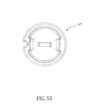
- FIG. 51 is a side view of the upper housing of the line holding mechanism of the embodiment shown in FIG. 25 ;
- FIG. 52 is a side perspective view of the upper housing of the line holding mechanism of the embodiment shown in FIG. 25 ;
- FIG. 53 is a top view of the upper housing of the line holding mechanism of the embodiment shown in FIG. 25 ;
- FIG. 54 shows a typical bearing sleeve used in the embodiment shown in FIG. 25 ;
- FIG. 55 is a cross-sectional cutaway view of the embodiment shown in FIG. 25 ;
- FIG. 56 is a side perspective view of a third embodiment of the present invention.
- FIG. 57 is a bottom perspective view of the embodiment shown in FIG. 56 with the ground contacting member removed;
- FIG. 58 is a top perspective view of the embodiment shown in FIG. 56 with the cover removed;
- FIG. 59 is a sliced view of the embodiment shown in FIG. 56 shown without the ground contacting member, taken between the two main layers of the main housing;
- FIG. 60 is a bottom view of the cover of the embodiment shown in FIG. 56 ;
- FIG. 61 is an inside perspective view of the ground contacting member of the embodiment shown in FIG. 56 ;
- FIG. 62 is a side perspective view of the line-holding mechanism of the embodiment shown in FIG. 56 with two bearing sleeves;
- FIG. 63 is a cutaway view through the main housing, line holding mechanism and bearing sleeves of the embodiment shown in FIG. 56 ;
- FIG. 64 is a cutaway view through the main housing, line holding mechanism and bearing sleeves of the embodiment shown in FIG. 56 depicted with the line holding mechanism removed;
- FIG. 65 is a cutaway line drawing of the line holding mechanism of the embodiment shown in FIG. 56 taken through the blade;
- FIG. 66 is a cutaway line drawing of the line holding mechanism of the embodiment shown in FIG. 56 taken through one of the line channels;
- FIG. 67 depicts the main housing of the embodiment shown in FIG. 56 ;
- FIG. 68 depicts the blade use to push the line out of the line channel
- FIG. 69 is a cutaway view of the blade pressed into the button
- FIG. 70 shows a perspective of a preferred embodiment of the present invention.
- FIG. 71 shows a side view of the embodiment shown in FIG. 70 with trimmer line extending from the line-holding mechanism
- FIG. 72 shows a bottom view of the embodiment shown in FIG. 70 with the trimmer line installed
- FIG. 73 shows the trimmer line pushed out from the trimmer head after the user has activated the button.
- FIG. 74 shows the button released, and the loop of trimmer line that can be pinched and pulled out of the head by the user.
- FIGS. 1-24 A first embodiment of the trimmer head 10 of the present invention is shown in FIGS. 1-24 .
- the embodiment shown in FIGS. 1-24 incorporates three line holding mechanisms 14 a - 14 c .
- One of the line holding mechanisms 14 is shown in FIG. 15 .
- the terms “line holding mechanism”, “pivoting post” and “pivot post” are used herein interchangeably.
- the head 10 comprises a main housing 11 and a cover 12 .
- the main housing 11 of the trimmer head 10 as shown in FIGS. 8 and 9 has three openings 29 for receiving each line holding mechanism 14 .
- Main housing 11 can best be seen in FIGS. 3, 4, 5, 8 and 9 .
- FIGS. 3 and 4 show the underside of main housing 11 and
- FIGS. 8 and 9 show the top of main housing 11 .
- the main housing 11 has three pairs of openings 26 a - 29 a .
- Main housing 11 is constructed of two spaced layers 19 and 21 (best seen in FIG. 5 ) connected by a central hub 25 .
- Each pair of openings are aligned vertically, one in each layer of the main housing 11 , and constructed so that the assembled line holding mechanism 14 can be inserted into the openings from above ( FIG. 9 shows line holding mechanism 14 inserted into opening).
- FIG. 9 shows line holding mechanism 14 inserted into opening.
- openings include upper plate opening 26 a , first lower plate opening 27 a , lower plate stop 28 a , and second lower plate opening 29 a .
- a bearing sleeve 17 e.g., as shown in FIG. 14
- cover 12 is placed over the main housing 11 to hold the line holding mechanisms in place.
- Cover 12 is fastened to the main housing 11 preferably using six screws 13 , as shown in FIG. 2 , although other fastening mechanisms used in the industry could also be utilized.
- cover 12 comprises a three-pronged shaped to accommodate the number of line holding mechanisms 14 utilized.
- Cover comprises opening 18 located in the center and shaped/sized to allow passage of a trimmer drive shaft there through to accomplish attachment of head 10 to trimmer device (not shown).
- FIG. 7 best shows cavities 23 a - 23 c for receiving of line holding mechanism 14 .
- Cover 12 and cavity 23 fit over line holding mechanism 14 .
- Opening 24 is shaped and sized to receive the main housing hub 25 to further secure cover to main housing.
- the trimmer head 10 is attached to a trimmer machine by placing a fastener (not shown) with a hexagon head into the hexagon shaped cavity 20 . Either the stem from the trimmer or the stem from a bolt would pass through the opening 18 shown in FIG. 2 . The head would then be rotated to turn the fastener, until the head was fully threaded onto the trimmer machine.
- the line holding mechanisms are confined vertically between the bearing sleeves 17 and the cover 12 , and are confined along their perimeters by the perimeter of each opening 26 a , 27 a , 29 a in the housing 11 .
- the line holding mechanisms 14 are allowed to pivot about a vertical axis.
- Each of the pivoting line holding mechanisms 14 are preferably assembled using five pieces, excluding the bearing sleeve 17 .
- the upper housing 16 for the line holding mechanism is shown separately in FIGS. 21-24 . This is placed over the lower housing 15 , shown separately in various views in FIGS. 16-20 .
- the upper housing 16 and lower housing 15 as assembled are shown in FIGS. 13 and 15 .
- the interior surfaces of the upper and lower housings are shaped such that when combined, each pair creates a passageway for holding a folded strip of line.
- the two line channels 35 are separated by interior surface rib 36 shown in FIG. 17 .
- Rib 32 further receives slot 33 from upper housing to secure line holding mechanism together.
- Interior surface 36 of lower housing provides support surface for upper plate and helps to define channels 35 . Opening 37 ( FIG.
- the line channels are not restricted to being parallel.
- the line channels are curvilinear, allowing the line to be loaded at a ninety degree angle from the exit position.
- the design is not restricted to a ninety degree orientation.
- the angle formed by the line portion entering the pivoting assembly relative to the line portion existing the pivoting assembly could be greater or less than ninety degrees.
- Each pivoting line holding mechanism 14 is designed to hold one folded strip of line. Referring to FIGS. 15 and 17 , the two distal ends of line are inserted into the openings 31 a and 31 b from the underside of main housing 11 . The trimmer line ends are pushed into the line channels 35 discussed above which are formed between the upper 16 and lower 15 housings. The line ends will follow the curvilinear path and will eit the line holding mechanism 14 at line outlets 30 a , 30 b located on the side of main housing 10 (see FIG. 10 ). The user would continue to push the line into the channel, or would pull the free ends of the trimmer line until the folded strip of line is fully inserted. This process would be repeated until a folded strip of trimmer line is installed into each of the three line-holding mechanisms for this embodiment.
- the preferred embodiment of the present invention has three pivoting line-holding mechanisms, spaced 120 degrees apart.
- other embodiments having various numbers of the pivoting line-holding mechanisms equally spaced would also function equally well.
- the trimmer head could be designed to have two pivoting line-holding mechanisms spaced 180 degrees apart, or four pivoting line-holding mechanisms, each equally spaced 90 degrees apart.
- five or more pivoting line-holding mechanisms could be used as long as the weight was uniformly distributed to allow for balanced rotation about a vertical axis.
- the number of screws or other mechanisms utilized to secure the cover to the main housing and thereby secure the line holding mechanisms within the head cavity may also vary accordingly.
- the outer most perimeter of the head is preferably round. However, this is not a functional requirement.
- the outer most perimeter of the head could be any shape as long as it was balanced with regards to rotational spinning about a vertical axis.
- FIGS. 25-55 is generally identical to the embodiment described above in FIGS. 1-24 but features an optional ground contacting member 111 and blade 119 .
- This embodiment incorporates three line-holding mechanisms 114 spaced 120 degrees apart.
- One of the line holding mechanisms 114 is shown in FIG. 35 .
- the main housing 112 of the trimmer head as shown in FIGS. 32 and 33 has three pairs of openings 124 .
- the main housing is constructed of two spaced layers connected by a central hub. Each pair of openings are aligned vertically, one in each layer of the main housing, and constructed so that the assembled line-holding mechanism can be inserted from above.
- a bearing sleeve 115 must first be inserted into the lower level of the opening 124 in the main housing.
- the line-holding mechanisms are confined vertically between the bearing sleeves 115 and the cover 113 , and are confined along their perimeters by the perimeter of each opening 124 in the housing 112 .
- the line-holding mechanisms 114 are allowed to pivot about a vertical axis within the limits defined by the impingement of the vertical walls 150 a and 150 b shown in FIG. 49 against the stop 149 shown on the inside of cover 113 in FIG. 31 .
- This limit to the rotation is not required for the functioning of the trimmer head, but assists in maintaining the pivot post in their preferred orientation, which is to have the exit holes 128 a and 128 b (shown in FIG. 49 ) pointing generally outward (away from the rotational center of the trimmer head).
- the trimmer head is attached to a trimmer machine by placing a fastener (not shown) with a hexagon head into the hexagon shaped cavity 122 . Either the stem from the trimmer or the stem from a bolt would pass through the opening 123 shown in FIGS. 29-32 . The head would then be rotated to turn the fastener, until the head was fully threaded onto the trimmer machine.
- the ground contacting member 111 is not shown. It would be added after the assembled trimmer head is attached to the powered rotary machine (string trimmer or brush cutter machine).
- the ground contacting member 111 attaches to the main housing by pushing the three tabs 121 (see FIG. 28 ) through the three slots 127 (see figure FIG. 32 ).
- use of the ground contacting member is optional.
- Each of the pivoting line-holding mechanisms 114 are preferably assembled using five pieces, excluding the bearing sleeve 115 shown in FIGS. 38 and 54 .
- the upper housing 117 for the line holding mechanism is shown separately in FIGS. 51-53 . This is placed over the lower housing 116 , shown separately in various views in FIGS. 47-50 .
- the upper housing 117 and lower housing 116 as assembled are shown in FIGS. 45 and 46 .
- the interior surfaces of the upper and lower housings are shaped such that when combined, each pair creates a passageway for holding a folded strip of line. At the upper end of this line passageway, the two line channels are separated by rib 143 shown in FIG. 48 .
- Each pivoting line-holding mechanism is designed to hold one folded strip of line (see FIGS. 70-74 ).
- the two distal ends of line are inserted into the openings 130 a and 130 b .
- the trimmer line ends are pushed into the line channels discussed above which are formed between the upper 117 and lower 116 housings.
- the line ends will follow the curvilinear path and will exit the line-holding mechanism 114 at channels 128 a and 128 b .
- the user would continue to push the line into the channel, or would pull the free ends of the trimmer line until the folded strip of line is fully inserted.
- FIGS. 70-72 show the line installed. This process would be repeated until a folded strip of trimmer line is installed into each of the three line-holding mechanisms for this embodiment.
- the distal ends of the folded strip of line will extend radially outward due to the centrifugal force caused by the rotation of the trimmer head. Due to the high spin rate the tips of the trimmer line are capable of cutting vegetation. However, if the tips of the trimmer line were to impact an immovable object such as a metal pole or rock, then the line-holding mechanism can pivot, allowing the trimmer line to momentarily move out of the way.
- the advantage of this pivoting action is that the line is less apt to break due to impacting an immovable object.
- the centrifugal force created by the rotational spinning of the trimmer head would cause the trimmer line to rotate the line-holding assemblies such that the line is again extending radially outward. This action of the line pivoting out of the way from an immovable object and then pivoting back to a radial position occurs repetitively until the trimmer line is clear of the immovable object.
- FIGS. 25-55 of the present invention comprises a trimmer head wherein the line-holding mechanism 114 comprises a spring-loaded, button activated blade 119 (see FIG. 38 ) that allows the user a means to push the used strip of line partially out of the line-holding mechanism.
- FIGS. 72-74 show this action.
- FIG. 72 shows the line strip installed with the blade 119 in the up position.
- FIG. 73 shows the blade in the down position.
- the user To move the blade into the downward position, the user must push button 118 , which in turn compresses spring 132 and moves blade 119 into the lower position. Then the user can release the button. Upon doing so, the spring will bias the blade back into the up position. This will leave a loop of line extending from the lower surface of the line-holding mechanism. This loop of line can then easily be pinched and pulled to remove the used strip of line.
- the incorporation of the spring-loaded, button activated blade in the pivoting line-holding mechanism provides the consumer with a novel product and a novel method for removing a used folded strip of trimmer line without the use of tools.
- blade 119 is preferably formed from a folded strip of metal.
- the folding action provides a nice radius 137 at the bottom of the blade for pushing against the folded strip of line.
- blade 119 could also be formed using a die casting process, or machined from metal using several commercial processes. It could also be molded of plastic.
- the lower end of the blade could be a blunt square tip or other shape, but the rounded lower end is preferred.
- the main shaft of the blade could be constructed differently. For example, a cylindrical shape could also be used.
- the upper end could also be fastened to the button using other means, such as a head placed on the upper end and pressed into a cavity of the button. Insert molding could also be used to attach the button to the blade shaft.
- the upper end of the blade 119 is projection 136 .
- the upper end of the blade is inserted into the channel 135 (see FIG. 41 ) of the button.
- the blade upper end is to be oriented such that its projection 136 will catch upon the ledge 134 once inserted.
- Ledge 134 (see FIGS. 39 and 40 ) will keep the blade 119 from being removed from the button.
- the spring 132 Prior to inserting the upper end of blade 119 into the button 118 , the spring 132 must be installed into the circular slot 133 shown in FIG. 39 .
- the cutaway in FIG. 38 shows the proper placement of the spring 132 in the line-holding mechanism 114 .
- the subassembly of the spring 132 , button 118 and the blade 119 are not locked into the lower housing 116 .
- FIG. 46 there is a passageway 138 which is open all the way through both the upper housing 117 and the lower housing 116 .
- the upper end of the blade 119 is pushed first through the opening 138 as in the lower housing 116 , then through the opening 38 in the upper housing 117 ( FIG. 45 ), then through the center of the spring 132 , and finally into the opening 135 in the button ( FIG. 41 ).
- the blade is pushed until the blade hook 136 catches on the ledge 134 shown in FIG. 40 . Once the blade hook catches on ledge 134 , then the assembly cannot be taken apart.
- There is a stop 140 on the inside bottom of the lower housing 116 ( FIG. 47 ) which limits the upward movement of blade 119 .
- the bearing sleeve 115 will have a lower edge 151 ( FIG. 54 ) that will rest on a ledge 153 located on the inside of openings 124 (see FIG. 32 for location of ledge 153 ).
- the ledge 153 located on the lower layer 155 of the main housing in combination with the bearing sleeve 152 will support the downward facing surfaces of the line-holding mechanism 114 .
- the novel design allows for a novel method for removing a used strip of folded trimmer line.
- the first step of the method involves the user pushing a button, which will cause a blade to push the folded portion on the trimmer line away from the lower surface of the line holding mechanism.
- the second step is for the user to release the button.
- the third step is for the user to then pinch the folded portion of line using the thumb and a finger tip.
- the fourth and final step is for the user to pull the line away from and out of the line holding mechanism.
- FIGS. 56-69 A third embodiment of the present invention is depicted in FIGS. 56-69 .
- the third embodiment functions generally in the same manner as the previous embodiment.
- the main differences between the embodiments is the shape of the perimeter head and the use of a second bearing sleeve on the pivoting line-holding mechanism in the third embodiment.
- the shape of the third embodiment is a head 1110 with three projections or legs. Each projection contains one pivot post assembly 1114 .
- the pivot post assembly is also called a line-holding assembly 1114 .
- pivoting line-holding assemblies are similar in design to the line-holding assemblies used in head 110 in the first embodiment. The difference is that the shape has been modified to function with two bearing sleeves 1115 a and 1115 b .
- Bearing sleeve 1115 a is mounted in the lower layer of the head 1155 .
- Bearing sleeve 1115 b is mounted in the upper layer of the head 1154 .
- the purpose of adding a second bearing sleeve is to improve the pivoting motion (to minimize the resistance to pivoting).
- the components in head 1110 have been numbered the same as the components in head 110 , with the exception that all components numbers used with head 1110 have been indexed by 1100 .
Abstract
Description
Claims (14)
Priority Applications (1)
| Application Number | Priority Date | Filing Date | Title |
|---|---|---|---|
| US14/765,082 US10178827B2 (en) | 2013-01-31 | 2014-01-31 | Trimmer head with pivoting posts |
Applications Claiming Priority (4)
| Application Number | Priority Date | Filing Date | Title |
|---|---|---|---|
| US201361758831P | 2013-01-31 | 2013-01-31 | |
| US201361829350P | 2013-05-31 | 2013-05-31 | |
| US14/765,082 US10178827B2 (en) | 2013-01-31 | 2014-01-31 | Trimmer head with pivoting posts |
| PCT/US2014/014283 WO2014121131A2 (en) | 2013-01-31 | 2014-01-31 | Trimmer head with pivoting posts |
Publications (2)
| Publication Number | Publication Date |
|---|---|
| US20150366131A1 US20150366131A1 (en) | 2015-12-24 |
| US10178827B2 true US10178827B2 (en) | 2019-01-15 |
Family
ID=51263122
Family Applications (1)
| Application Number | Title | Priority Date | Filing Date |
|---|---|---|---|
| US14/765,082 Active 2035-05-14 US10178827B2 (en) | 2013-01-31 | 2014-01-31 | Trimmer head with pivoting posts |
Country Status (3)
| Country | Link |
|---|---|
| US (1) | US10178827B2 (en) |
| CA (1) | CA2899871C (en) |
| WO (1) | WO2014121131A2 (en) |
Families Citing this family (13)
| Publication number | Priority date | Publication date | Assignee | Title |
|---|---|---|---|---|
| US9801335B2 (en) * | 2014-03-20 | 2017-10-31 | Shakespeare Company, Llc | Trimmer head and method of installing pivot posts therein |
| US9986682B2 (en) * | 2014-06-05 | 2018-06-05 | Shakespeare Company, Llc | Trimmer head with pivot posts holding a single strip of line |
| USD756728S1 (en) * | 2014-12-15 | 2016-05-24 | George E. Alliss | Figure eight holed line mount for a string trimmer head |
| USD813000S1 (en) | 2016-03-18 | 2018-03-20 | Tecomec S.R.L. | Head trimmer |
| US10070582B2 (en) | 2016-04-20 | 2018-09-11 | Tti (Macao Commercial Offshore) Limited | String trimmer head |
| USD823080S1 (en) | 2016-10-07 | 2018-07-17 | Tecomec S.R.L. | Head trimmer |
| USD826013S1 (en) * | 2016-10-07 | 2018-08-21 | Tecomec S.R.L. | Head trimmer |
| USD826663S1 (en) * | 2016-10-07 | 2018-08-28 | Tecomec S.R.L. | Head trimmer |
| USD831448S1 (en) | 2017-06-28 | 2018-10-23 | Tecomec S.R.L. | Head trimmer |
| USD907973S1 (en) * | 2018-10-09 | 2021-01-19 | KPI—Kiwk Products, Inc. | Housing for flexible line on a rotary trimmer |
| USD929828S1 (en) * | 2018-10-09 | 2021-09-07 | KPI—Kwik Products, Inc. | Housing for flexible line on a rotary trimmer |
| CA3065995A1 (en) | 2019-01-03 | 2020-07-03 | Techtronic Cordless Gp | Trimmer head assembly for a trimmer |
| MX2020000525A (en) | 2019-01-25 | 2020-08-20 | Techtronic Cordless Gp | Trimmer head assembly for a trimmer. |
Citations (9)
| Publication number | Priority date | Publication date | Assignee | Title |
|---|---|---|---|---|
| US20050126017A1 (en) * | 2003-12-12 | 2005-06-16 | Robert L. Phillips | String trimmer head |
| JP2007175013A (en) | 2005-12-28 | 2007-07-12 | Starting Ind Co Ltd | Rotary cutter for bush cleaner |
| US7257898B2 (en) * | 2004-04-16 | 2007-08-21 | Kwik Products, Inc. | Cutting head for string trimmer |
| US20090031567A1 (en) | 2007-08-02 | 2009-02-05 | Robert L. Phillips | Fixed line trimmer head with ease of loading |
| US20090038163A1 (en) * | 2007-08-10 | 2009-02-12 | Orlando Jerez | Weed trimming apparatus, weed trimmer head, and trimmer line retention device |
| US7536792B2 (en) * | 2007-01-03 | 2009-05-26 | Moore Mark R | Head for a rotary line trimmer apparatus |
| JP2009171929A (en) | 2008-01-28 | 2009-08-06 | Diatop Kk | Reaping head |
| US7603782B2 (en) | 2004-12-01 | 2009-10-20 | Orlando Jerez | Universal, trimmer line, hook disk system |
| US20110289785A1 (en) | 2010-06-01 | 2011-12-01 | Orlando Jerez | Rotary Trimmer Apparatus And Related Rotary Head Assembly |
Family Cites Families (1)
| Publication number | Priority date | Publication date | Assignee | Title |
|---|---|---|---|---|
| US6347455B2 (en) * | 1999-12-20 | 2002-02-19 | Murray, Inc. | String trimmer head |
-
2014
- 2014-01-31 CA CA2899871A patent/CA2899871C/en not_active Expired - Fee Related
- 2014-01-31 US US14/765,082 patent/US10178827B2/en active Active
- 2014-01-31 WO PCT/US2014/014283 patent/WO2014121131A2/en active Application Filing
Patent Citations (10)
| Publication number | Priority date | Publication date | Assignee | Title |
|---|---|---|---|---|
| US20050126017A1 (en) * | 2003-12-12 | 2005-06-16 | Robert L. Phillips | String trimmer head |
| US7257898B2 (en) * | 2004-04-16 | 2007-08-21 | Kwik Products, Inc. | Cutting head for string trimmer |
| US7603782B2 (en) | 2004-12-01 | 2009-10-20 | Orlando Jerez | Universal, trimmer line, hook disk system |
| US7743511B2 (en) | 2004-12-01 | 2010-06-29 | Orlando Jerez | Powered disk preferably with oscillateable, trimmer-line-hook mounts |
| JP2007175013A (en) | 2005-12-28 | 2007-07-12 | Starting Ind Co Ltd | Rotary cutter for bush cleaner |
| US7536792B2 (en) * | 2007-01-03 | 2009-05-26 | Moore Mark R | Head for a rotary line trimmer apparatus |
| US20090031567A1 (en) | 2007-08-02 | 2009-02-05 | Robert L. Phillips | Fixed line trimmer head with ease of loading |
| US20090038163A1 (en) * | 2007-08-10 | 2009-02-12 | Orlando Jerez | Weed trimming apparatus, weed trimmer head, and trimmer line retention device |
| JP2009171929A (en) | 2008-01-28 | 2009-08-06 | Diatop Kk | Reaping head |
| US20110289785A1 (en) | 2010-06-01 | 2011-12-01 | Orlando Jerez | Rotary Trimmer Apparatus And Related Rotary Head Assembly |
Also Published As
| Publication number | Publication date |
|---|---|
| CA2899871A1 (en) | 2014-08-07 |
| WO2014121131A3 (en) | 2015-01-15 |
| WO2014121131A2 (en) | 2014-08-07 |
| US20150366131A1 (en) | 2015-12-24 |
| CA2899871C (en) | 2017-05-30 |
Similar Documents
| Publication | Publication Date | Title |
|---|---|---|
| US10178827B2 (en) | Trimmer head with pivoting posts | |
| US10440881B2 (en) | Weed trimming apparatus, weed trimmer head, and trimmer line retention device | |
| US10278327B2 (en) | Trimmer head for use with line and blades | |
| US4068376A (en) | Flexible cutting line and rotor therefor | |
| US8001694B2 (en) | Fixed line rotary head trimmer with quick friction rotational lock for string trimmer machine | |
| US7878097B2 (en) | Powered weed trimmer cutting head and method | |
| US7412768B2 (en) | Invertible trimmer line spool for a vegetation trimmer apparatus | |
| US6928741B2 (en) | Fixed line head for flexible line rotary trimmers | |
| US8973274B2 (en) | Fixed line head for flexible line rotary trimmers | |
| US8181560B2 (en) | Food processing tool | |
| US8640588B2 (en) | Powered weed trimmer cutting head and method | |
| US6854185B1 (en) | Vegetation trimmer apparatus | |
| US20160227705A1 (en) | String trimmer head | |
| US20070084061A1 (en) | Mechanism for attaching trimmer line strips to a head of a trimming apparatus | |
| EP2554039B1 (en) | Brush cutter | |
| US20060254061A1 (en) | Vegetation trimmer apparatus | |
| US20100083506A1 (en) | Head section for a rotary cutting device including blades and individual cutting lines | |
| EP3288364A1 (en) | Quick loading trimmer head and trimmer thereto | |
| EP2724602B1 (en) | A rotary cutting head system | |
| US20060254060A1 (en) | Vegetation trimmer apparatus | |
| EP3536140B1 (en) | String trimmer attachment for a trimmer head | |
| CA3098902A1 (en) | Cross-flow horizontal rotary mower | |
| US9861034B2 (en) | Trimmer head with incorporated line cutter | |
| WO2015143288A1 (en) | Improved pivot posts & trimmer heads utilizing the same | |
| CA2654671A1 (en) | Powered weed trimmer cutting head and method |
Legal Events
| Date | Code | Title | Description |
|---|---|---|---|
| AS | Assignment |
Owner name: SHAKESPEARE COMPANY, LLC, SOUTH CAROLINA Free format text: ASSIGNMENT OF ASSIGNORS INTEREST;ASSIGNOR:SKINNER, DAVID B.;REEL/FRAME:036225/0854 Effective date: 20140131 |
|
| STCF | Information on status: patent grant |
Free format text: PATENTED CASE |
|
| AS | Assignment |
Owner name: CREDIT SUISSE AG, CAYMAN ISLANDS BRANCH, AS COLLAT Free format text: SECURITY INTEREST;ASSIGNORS:JARDEN ZINC PRODUCTS, LLC;LIFOAM INDUSTRIES, LLC;SHAKESPEARE COMPANY, LLC;AND OTHERS;REEL/FRAME:049122/0163 Effective date: 20190501 Owner name: CREDIT SUISSE AG, CAYMAN ISLANDS BRANCH, AS COLLATERAL AGENT, CAYMAN ISLANDS Free format text: SECURITY INTEREST;ASSIGNORS:JARDEN ZINC PRODUCTS, LLC;LIFOAM INDUSTRIES, LLC;SHAKESPEARE COMPANY, LLC;AND OTHERS;REEL/FRAME:049122/0163 Effective date: 20190501 |
|
| MAFP | Maintenance fee payment |
Free format text: PAYMENT OF MAINTENANCE FEE, 4TH YEAR, LARGE ENTITY (ORIGINAL EVENT CODE: M1551); ENTITY STATUS OF PATENT OWNER: LARGE ENTITY Year of fee payment: 4 |