US10178748B1 - X-ray spot stability - Google Patents
X-ray spot stability Download PDFInfo
- Publication number
- US10178748B1 US10178748B1 US15/455,856 US201715455856A US10178748B1 US 10178748 B1 US10178748 B1 US 10178748B1 US 201715455856 A US201715455856 A US 201715455856A US 10178748 B1 US10178748 B1 US 10178748B1
- Authority
- US
- United States
- Prior art keywords
- anode
- fins
- insulator
- electrical
- array
- Prior art date
- Legal status (The legal status is an assumption and is not a legal conclusion. Google has not performed a legal analysis and makes no representation as to the accuracy of the status listed.)
- Active, expires
Links
Images


Classifications
-
- H—ELECTRICITY
- H05—ELECTRIC TECHNIQUES NOT OTHERWISE PROVIDED FOR
- H05G—X-RAY TECHNIQUE
- H05G1/00—X-ray apparatus involving X-ray tubes; Circuits therefor
- H05G1/02—Constructional details
- H05G1/025—Means for cooling the X-ray tube or the generator
-
- H—ELECTRICITY
- H01—ELECTRIC ELEMENTS
- H01J—ELECTRIC DISCHARGE TUBES OR DISCHARGE LAMPS
- H01J35/00—X-ray tubes
- H01J35/02—Details
- H01J35/04—Electrodes ; Mutual position thereof; Constructional adaptations therefor
- H01J35/06—Cathodes
-
- H—ELECTRICITY
- H01—ELECTRIC ELEMENTS
- H01J—ELECTRIC DISCHARGE TUBES OR DISCHARGE LAMPS
- H01J35/00—X-ray tubes
- H01J35/02—Details
- H01J35/04—Electrodes ; Mutual position thereof; Constructional adaptations therefor
- H01J35/06—Cathodes
- H01J35/064—Details of the emitter, e.g. material or structure
-
- H—ELECTRICITY
- H01—ELECTRIC ELEMENTS
- H01J—ELECTRIC DISCHARGE TUBES OR DISCHARGE LAMPS
- H01J35/00—X-ray tubes
- H01J35/02—Details
- H01J35/04—Electrodes ; Mutual position thereof; Constructional adaptations therefor
- H01J35/08—Anodes; Anti cathodes
-
- H—ELECTRICITY
- H01—ELECTRIC ELEMENTS
- H01J—ELECTRIC DISCHARGE TUBES OR DISCHARGE LAMPS
- H01J35/00—X-ray tubes
- H01J35/02—Details
- H01J35/04—Electrodes ; Mutual position thereof; Constructional adaptations therefor
- H01J35/08—Anodes; Anti cathodes
- H01J35/12—Cooling non-rotary anodes
-
- H—ELECTRICITY
- H01—ELECTRIC ELEMENTS
- H01J—ELECTRIC DISCHARGE TUBES OR DISCHARGE LAMPS
- H01J35/00—X-ray tubes
- H01J35/02—Details
- H01J35/04—Electrodes ; Mutual position thereof; Constructional adaptations therefor
- H01J35/08—Anodes; Anti cathodes
- H01J35/12—Cooling non-rotary anodes
- H01J35/13—Active cooling, e.g. fluid flow, heat pipes
-
- H—ELECTRICITY
- H01—ELECTRIC ELEMENTS
- H01J—ELECTRIC DISCHARGE TUBES OR DISCHARGE LAMPS
- H01J35/00—X-ray tubes
- H01J35/02—Details
- H01J35/16—Vessels; Containers; Shields associated therewith
- H01J35/18—Windows
-
- H—ELECTRICITY
- H01—ELECTRIC ELEMENTS
- H01J—ELECTRIC DISCHARGE TUBES OR DISCHARGE LAMPS
- H01J2235/00—X-ray tubes
- H01J2235/12—Cooling
- H01J2235/1204—Cooling of the anode
-
- H—ELECTRICITY
- H01—ELECTRIC ELEMENTS
- H01J—ELECTRIC DISCHARGE TUBES OR DISCHARGE LAMPS
- H01J2235/00—X-ray tubes
- H01J2235/12—Cooling
- H01J2235/1225—Cooling characterised by method
- H01J2235/1291—Thermal conductivity
- H01J2235/1295—Contact between conducting bodies
-
- H—ELECTRICITY
- H01—ELECTRIC ELEMENTS
- H01J—ELECTRIC DISCHARGE TUBES OR DISCHARGE LAMPS
- H01J2235/00—X-ray tubes
- H01J2235/16—Vessels
Definitions
- the present application is related generally to x-ray tubes.
- a location where an x-ray beam hits a sample is called an x-ray spot.
- the x-ray source is used with polycapillary focusing optics, it can be important for the x-ray spot to be stable (i.e. does not fluctuate over time). Temperature changes of, and temperature differentials within, the x-ray source can cause instability or fluctuation of the x-ray spot.
- x-ray tubes can have large pathways for removal of heat, but some x-ray tubes (e.g. for a portable x-ray source) need small size, and can't afford large pathways for removal of heat. Therefore, it can be more difficult to provide x-ray spot stability in these small x-ray tubes.
- X-ray tubes are often cooled by a heat exchanger carrying a liquid coolant. Such a cooling method may be impractical for a portable x-ray source.
- the present invention is directed to various embodiments of x-ray tubes that satisfy these needs. Each embodiment may satisfy one or more of these needs.
- the x-ray tube can comprise an anode that is electrically-conductive and that includes a target material configured for production and emission of x-rays in response to impinging electrons; and a cathode, electrically insulated from the anode, and having an electron-emitter capable of emitting electrons towards the target material on the anode.
- the target material can have a target displacement less than 60 micrometers, where the target displacement is a displacement of the target material, towards the electron-emitter, along a longitudinal-axis of the anode, from x-ray powered-off state to stable operation at 40 watts, based on elongation of the anode.
- the x-ray tube can be small.
- a distance from the electron-emitter to the target material can be less than 40 millimeters and/or a distance from the x-ray window to a center of the target material can be less than 25 millimeters.
- the x-ray tube can include a heatsink with a base located closer to the anode and an array of fins extending from the base away from the anode in opposite directions with first distal ends at one end and second distal ends at an opposite end.
- a first fan can be attached to the first distal ends of the array of fins, oriented to face the base, and configured to direct an airstream towards the base.
- a second fan can be attached to the second distal ends of the array of fins, oriented to face away from the base, and configured to draw the airstream from the base.
- An air flow path can extend from the first fan to the second fan within array of fins. Plates can be located on sides of the fins and can be configured to direct air flow from the first fan to the second fan.
- the x-ray tube can include an electrical-insulator encircling the anode and electrically insulating the cathode from the anode and a heatsink attached to and in thermal contact with the electrical-insulator.
- FIG. 1 is a schematic, cross-sectional side-view of an x-ray source 10 , comprising an x-ray tube 27 and a power supply 24 , the x-ray tube 27 including a cathode 13 , an anode 11 , an electrical-insulator 15 encircling the anode 11 , a heatsink 19 attached to the electrical-insulator 15 , and two fans 21 located at opposite ends of fins 19 f of the heatsink 19 , in accordance with an embodiment of the present invention.
- FIG. 2 is a schematic side-view of the x-ray tube 27 of FIG. 1 , in accordance with an embodiment of the present invention.
- FIG. 3 is a schematic side-view of the x-ray tube 27 of FIG. 2 , with a first plate 31 located on a first lateral side 29 f of the fins 19 f and blocking at least a portion of gaps G between the fins 19 f to direct flow from one fan 21 to the other and across a base 19 b of the heatsink 19 , in accordance with an embodiment of the present invention.
- FIG. 4 is a schematic end-view of the x-ray tube 27 of FIG. 3 , showing the first plate 31 located on the first lateral side 29 f of the fins 19 f , and a second plate 41 located on a second lateral side 29 s of the fins 19 f , that is opposite of the first lateral side 29 f , and blocking at least a portion of gaps G between the fins 19 f to direct flow from one fan 21 to the other and across a base 19 b of the heatsink 19 , in accordance with an embodiment of the present invention.
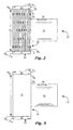
- FIG. 5 is a schematic side-view of an x-ray tube 57 , similar to x-ray tubes 27 in FIGS. 1-4 , except with fins 19 f extending in a single direction away from the base 19 b of the heatsink 19 and only a single fan 21 , in accordance with an embodiment of the present invention.
- FIG. 6 is a schematic side-view of the x-ray tube 57 of FIG. 5 , with a first plate 31 located on a first lateral side 29 f of the fins 19 f and blocking at least a portion of gaps G between the fins 19 f to direct flow from one fan 21 to and across the base 19 b of the heatsink 19 , in accordance with an embodiment of the present invention.
- FIG. 7 is a schematic end-view of the x-ray tube 57 of FIG. 6 , showing the first plate 31 located on the first lateral side 29 f of the fins 19 f , and a second plate 41 located on a second lateral side 29 s of the fins 19 f , that is opposite of the first lateral side 29 f , and blocking at least a portion of gaps G between the fins 19 f to direct flow from one fan 21 to and across a base 19 b of the heatsink 19 , in accordance with an embodiment of the present invention.
- an x-ray source 10 comprising a power supply 24 electrically coupled to an x-ray tube 27 .
- Various views and embodiments of the x-ray tube 27 , without the power supply 24 are also shown in FIGS. 2-4 .
- X-ray tube 57 shown in FIGS. 5-7 , is similar to x-ray tube 27 , except for a difference in structure of the heatsink 19 , as will be described below.
- the x-ray tubes 27 and 57 can include an anode 11 and a cathode 13 .
- the anode 11 can be electrically-conductive and can include a target material 11 T configured for production and emission of x-rays 17 in response to impinging electrons 16 .
- the cathode 13 can be electrically insulated from the anode 11 and can have an electron-emitter 12 capable of emitting electrons 16 towards the target material 11 T on the anode 11 .
- the x-ray tubes 27 and 57 are side-window x-ray tubes.
- the invention may be more useful to side-window x-ray tubes; however, the invention may also be applicable to transmission-target x-ray tubes.
- the x-ray window 14 can be electrically-insulated from the anode 11 and can be electrically-coupled to the cathode 13 .
- the x-ray window 14 can be spaced apart from the target material 11 T of the anode 11 and can be located to allow transmission of the x-rays 17 through the x-ray window 14 and out of the x-ray tube 27 or 57 .
- the x-ray window 14 can include some or all of the properties (e.g. low deflection, high x-ray transmissivity, low visible and infrared light transmissivity) of the x-ray window described in U.S. patent application Ser. No. 14/597,955, filed on Jan. 15, 2015, which is incorporated herein by reference in its entirety.
- the x-ray spot can change due to expansion and contraction of the anode 11 as the temperature changes.
- the anode 11 of x-ray tubes 27 and 57 expand and contract along a longitudinal-axis 11 L of the anode 11 the x-ray spot can shift. This can cause problems in some x-ray applications, such as for example if the x-ray tubes 27 and 57 are used with polycapillary focusing optics.
- the x-ray tubes 27 and 57 can include an electrical-insulator 15 , electrically insulating the cathode 13 from the anode 11 (of course a vacuum also electrically insulates the cathode 13 from the anode 11 along a different potential electrical-current path).
- the electrical-insulator 15 can be made of various electrically-insulative materials, including ceramic or glass.
- a hole 25 can extend through the electrical-insulator 15 .
- the anode 11 can extend partially or completely through the hole 25 .
- the original length L o of the region that affects the change in length ⁇ L of the anode 11 , in regard to motion of the target material 11 T and motion of the x-ray spot, is based on a location of attachment of the anode 11 to the electrical-insulator 15 .
- the original length L o and thus also the change in length ⁇ L, can be reduced by attaching the anode closer to the proximal-end 25 p of the hole 25 of the electrical-insulator 15 .
- a bond e.g. hermetic-bond
- the electrical-insulator 15 to the anode 11 can be located at the proximal-end 25 p of the hole 25 in one aspect, within 3 millimeters of the proximal-end 25 p of the hole 25 in another aspect, or within 6 millimeters of the proximal-end 25 p of the hole 25 in another aspect.
- the original length L o of the region that affects the change in length ⁇ L of the anode 11 can be a distance D 7 between the center of the target material 11 T of the anode 11 and the proximal-end 25 p .
- This distance D 7 can be small, such as for example less than 20 millimeters in one aspect, less than 10 millimeters in another aspect, or less than 7 millimeters in another aspect.
- the length L o of the region that affects the change in length ⁇ L of the anode 11 can be the relatively large distance D 8 between the center of the target material 11 T of the anode 11 and the distal-end 23 p .
- the change in length ⁇ L can also be reduced by selection of a material, for part or all of the anode 11 , with a relatively small coefficient of linear thermal expansion ⁇ at 20° C., such as for example less than 5 ⁇ m/(m*K) in one aspect, less than 6 ⁇ m/(m*K) in another aspect, or less than 10 ⁇ m/(m*K) in another aspect.
- all or part of the anode can be made of tungsten, with a coefficient of linear thermal expansion ⁇ of about 4.5 ⁇ m/(m*K) at 20° C.
- the change in length ⁇ L can also be reduced by reducing the change in temperature ⁇ T during operation of the x-ray tubes 27 and 57 .
- a heatsink 19 can be attached to the electrical-insulator 15 .
- the heatsink can be directly attached to the electrical-insulator 15 , such that there is minimal distance D 3 between the heatsink 19 and the electrical-insulator 15 , such as for example less than 0.1 millimeter in one aspect, less than 1 millimeter in another aspect, or less than 3 millimeters in another aspect.
- the heatsink can be directly attached to the electrical-insulator 15 by a material with a high thermal conductivity, such as for example a silver epoxy.
- a material with a high thermal conductivity such as for example a silver epoxy.
- Use of an electrical-insulator 15 made of a material with a high thermal conductivity, can also improve heat transfer and reduce the change in temperature ⁇ T. For example, many ceramics have higher thermal conductivities than potting materials. Thus, the electrical-insulator 15 can be made partly or entirely of ceramic.
- a straight-line path 28 from an inside of the electrical-insulator 15 , proximate the anode 11 , through the electrical-insulator 15 , through the heatsink 19 to an outer-surface of the heatsink 19 can pass only through materials having a relatively high coefficient of thermal conductivity, such as for example, at least 2.0 W/m*K in one aspect, at least 10 W/m*K in another aspect, or at least 20 W/m*K in another aspect.
- the electrical-insulator 15 can have a thickness D 4 , from an inner diameter proximate the anode 11 to an outer diameter proximate the heatsink 19 , of less than 25 millimeters in one aspect, less than 12 millimeters in another aspect, or less than 10 millimeters in another aspect.
- a heatsink with air cooling can be used instead of a heat exchanger with a liquid coolant.
- a heatsink with air cooling can be used instead of a heat exchanger with a liquid coolant.
- the heatsink 19 can have a base 19 b proximate the electrical-insulator 15 and an array of fins 19 f .
- the array of fins 19 f can be elongated and can extend outwards away from the electrical-insulator 15 in opposite directions with first distal ends 19 d1 at one end and second distal ends 19 d2 at an opposite end.
- a first fan 21 a can be attached to the first distal ends 19 d1 , oriented to face the base 19 b , and configured to direct an airstream towards the base 19 b .
- a second fan 21 b can be attached to the second distal ends 19 d2 , oriented to face away from the base 19 b , and configured to draw the airstream away from the base 19 b .
- An air flow path 22 can extend from the first fan 21 a to the second fan 21 b within array of fins 19 f .
- a first lateral side 29 f of the array of fins 19 f can extend from the first distal ends 19 d1 to the second distal ends 19 d2 .
- a second lateral side 29 s of the array of fins 19 f can extend from the first distal ends 19 d1 to the second distal ends 19 d2 at an opposite side of the array of fins 19 f from the first lateral side 29 f .
- a first plate 31 can be located on the first lateral side 29 f .
- the first plate 31 can have a length L 1 to block gaps G between the fins 19 f on the first lateral side 29 f .
- the first plate 31 can have a length L 1 of at least 70% in one aspect, at least 80% in another aspect, at least 90% In another aspect, or at least 95% in another aspect, of a distance D 9 between the first distal ends 19 d1 and the second distal ends 19 d2 on the first lateral side 29 f .
- the first plate 31 can block at least 70% of the gaps G in one aspect, at least 80% of the gaps G in another aspect, at least 90% of the gaps G in another aspect, at least 95% of the gaps G in another aspect.
- the first plate 31 by its length L 1 and location, can thus be configured to direct air flow from the first fan 21 a to the second fan 21 b .
- a second plate 41 can be located on the second lateral side 29 s .
- the second plate 41 can have a length L 2 to block gaps G between the fins 19 f on the second lateral side 29 s .
- the second plate 31 can have a length L 2 of at least 70% in one aspect, at least 80% in another aspect, at least 90% In another aspect, or at least 95% in another aspect, of a distance D 9 between the first distal ends 19 d1 and the second distal ends 19 d2 on the second lateral side 29 s .
- the second plate 31 can block at least 70% of the gaps G in one aspect, at least 80% of the gaps G in another aspect, at least 90% of the gaps G in another aspect, at least 95% of the gaps G in another aspect.
- the second plate 41 by its length L 2 and location, can thus be configured to direct air flow from the first fan 21 a to the second fan 21 b .
- the array of fins 19 f can be elongated and can extend outwards away from the electrical-insulator 15 , from proximal ends 59 p at the base 19 b to distal ends 59 d away from the base 19 b , and can have a height H extending between the proximal ends 59 p and the distal ends 59 d .
- a fan 21 can be located adjacent to the distal ends 59 d of the array of fins 19 f and can be oriented to face the base 19 b and can be configured to direct an airstream towards the base 19 b .
- An air flow path 52 can extend from the fan 21 at the distal ends 59 d of the array of fins 19 f , along the array of fins 19 f to the base 19 b , and out a first lateral side 29 f of the array of fins 19 f .
- a first plate 31 can be located at the first lateral side 29 f of the array of fins 19 f and can extend from the distal ends 59 d of the array of fins 19 f towards the base 19 b .
- the first plate 31 can have a length L 1 designed for optimal size and direction of the air flow path 52 to direct air flow from the fan to the base 19 b of the heatsink 19 .
- the length L 1 can be at least 25% of the height H of the array of fins 19 f in one aspect, at least 50% of the height H of the array of fins 19 f in another aspect, at least 75% of the height H of the array of fins 19 f in another aspect, or at least 90% of the height H of the array of fins 19 f in another aspect.
- a second plate 41 can be located at a second lateral side 29 s of the array of fins 19 f .
- the second lateral side 29 s can be opposite of the first lateral side 29 f .
- the second plate 41 can extend from the distal ends 59 d of the array of fins 19 f towards the base 19 b .
- the second plate 41 can have a length L 2 designed for optimal size and direction of the air flow path 52 to direct air flow from the fan to the base 19 b of the heatsink 19 .
- the length L 2 can be at least 25% of the height H of the array of fins 19 f in one aspect, at least 50% of the height H of the array of fins 19 f in another aspect, at least 75% of the height H of the array of fins 19 f in another aspect, or at least 90% of the height H of the array of fins 19 f in another aspect.
- Displacement of the target material 11 T can be reduced by a design that includes elements as just described, such as one or more of: (a) reducing a length L o the anode 11 (or at least reducing a portion of the anode 11 that can affect target material 11 T location by thermal expansion and contraction); (b) reducing the coefficient of linear thermal expansion ⁇ ; and (c) improving heat transfer to reduce the change in temperature ⁇ T.
- the target material 11 T can have a target displacement less than 100 micrometers in one aspect, less than 60 micrometers in another aspect, less than 40 micrometers in another aspect, less than 20 micrometers in another aspect, or less than 10 micrometers in another aspect, where the target displacement is a displacement of the target material 11 T , towards the electron-emitter 12 , along a longitudinal-axis 11 L of the anode 11 , from x-ray powered-off state to stable operation at 40 watts, based on elongation of the anode 11 .
- x-ray tubes can have large pathways for removal of heat, but some x-ray tubes (e.g. for a portable x-ray source) need small size, and can't afford large pathways for removal of heat. It can be more difficult to provide x-ray spot stability in these small x-ray tubes.
- X-ray tubes are often cooled by a heat exchanger carrying a liquid coolant. Such a cooling method may be impractical for a portable x-ray source.
- the present invention is especially applicable to small x-ray tubes.
- small examples include the following:
- the electrical-insulator 15 can be located at least partially inside of a bore 23 extending through heatsink 19 .
- An electrically-conductive adhesive can attach the heatsink 19 to the electrical-insulator 15 .
- a short-circuit between the heatsink 19 and the cathode 13 can be caused by some of this electrically-conductive adhesive extending from the heatsink 19 to the cathode.
- An annular-groove 18 can be located at an interface of the electrical-insulator 15 and the heatsink 19 ; can be radially-perpendicular to a longitudinal-axis 11 L of the bore 23 ; can be cut into an inner-face of the heatsink 19 , an outer-face of the electrical-insulator 15 , or both; and can be configured to contain excess adhesive that binds the electrical-insulator 15 to the heatsink 19 .
- This annular-groove 18 can help avoid a short-circuit between the heatsink 19 and the cathode 13 caused by the electrically-conductive adhesive.
- the annular-groove 18 can be located at or near an end 23 p of the bore that is closest to the electron-emitter 12 , such as for example within 3 millimeters of this end 23 p .
- the design of the x-ray tubes 27 and 57 described herein can allow a relatively large voltage differential between the cathode 13 and the anode 11 and can be operated at relatively high power (relative to other, similar-sized, x-ray tubes).
- the x-ray tubes 27 and 57 can form part of an x-ray source 10 , the x-ray source 10 comprising a power supply 24 electrically coupled to the x-ray tube 27 or 57 .
- the x-ray source 10 can provide at least 25 watts of x-ray emission continuously for at least 1 hour.
Landscapes
- Physics & Mathematics (AREA)
- Fluid Mechanics (AREA)
- X-Ray Techniques (AREA)
Abstract
An x-ray tube can provide x-ray spot stability, even for a small x-ray tube. The x-ray tube can have small target displacement, where target displacement is a displacement of the target material, towards the electron-emitter, along a longitudinal-axis of the anode, from x-ray powered-off state to stable operation, based on elongation of the anode. The x-ray tube can include a heatsink with an array of fins extending away from a base in opposite directions. A first fan can be attached to one end of the array of fins, oriented to face the base, and configured to direct an airstream towards the base. A second fan can be attached to opposite ends, oriented to face away from the base, and configured to draw the airstream from the base. Plate(s) can be located on sides of the fins to direct air flow from the first fan to the second fan.
Description
Priority is claims to U.S. Provisional Patent Application No. 62/352,334, filed Jun. 20, 2016, which is hereby incorporated herein by reference.
The present application is related generally to x-ray tubes.
A location where an x-ray beam hits a sample is called an x-ray spot. In some applications, especially if the x-ray source is used with polycapillary focusing optics, it can be important for the x-ray spot to be stable (i.e. does not fluctuate over time). Temperature changes of, and temperature differentials within, the x-ray source can cause instability or fluctuation of the x-ray spot.
It would be beneficial to increase positional stability of the x-ray spot. Large x-ray tubes can have large pathways for removal of heat, but some x-ray tubes (e.g. for a portable x-ray source) need small size, and can't afford large pathways for removal of heat. Therefore, it can be more difficult to provide x-ray spot stability in these small x-ray tubes. X-ray tubes are often cooled by a heat exchanger carrying a liquid coolant. Such a cooling method may be impractical for a portable x-ray source.
It has been recognized that it would be advantageous to increase positional stability of the x-ray spot, especially for small and portable x-ray sources, and to avoid the need for a heat exchanger. The present invention is directed to various embodiments of x-ray tubes that satisfy these needs. Each embodiment may satisfy one or more of these needs.
The x-ray tube can comprise an anode that is electrically-conductive and that includes a target material configured for production and emission of x-rays in response to impinging electrons; and a cathode, electrically insulated from the anode, and having an electron-emitter capable of emitting electrons towards the target material on the anode.
In one embodiment, the target material can have a target displacement less than 60 micrometers, where the target displacement is a displacement of the target material, towards the electron-emitter, along a longitudinal-axis of the anode, from x-ray powered-off state to stable operation at 40 watts, based on elongation of the anode.
In another embodiment, the x-ray tube can be small. For example, a distance from the electron-emitter to the target material can be less than 40 millimeters and/or a distance from the x-ray window to a center of the target material can be less than 25 millimeters.
In another embodiment, the x-ray tube can include a heatsink with a base located closer to the anode and an array of fins extending from the base away from the anode in opposite directions with first distal ends at one end and second distal ends at an opposite end. A first fan can be attached to the first distal ends of the array of fins, oriented to face the base, and configured to direct an airstream towards the base. A second fan can be attached to the second distal ends of the array of fins, oriented to face away from the base, and configured to draw the airstream from the base. An air flow path can extend from the first fan to the second fan within array of fins. Plates can be located on sides of the fins and can be configured to direct air flow from the first fan to the second fan.
In another embodiment, the x-ray tube can include an electrical-insulator encircling the anode and electrically insulating the cathode from the anode and a heatsink attached to and in thermal contact with the electrical-insulator.
As illustrated in FIG. 1 , an x-ray source 10 is shown comprising a power supply 24 electrically coupled to an x-ray tube 27. Various views and embodiments of the x-ray tube 27, without the power supply 24, are also shown in FIGS. 2-4 . X-ray tube 57, shown in FIGS. 5-7 , is similar to x-ray tube 27, except for a difference in structure of the heatsink 19, as will be described below. The x-ray tubes 27 and 57 can include an anode 11 and a cathode 13. The anode 11 can be electrically-conductive and can include a target material 11 T configured for production and emission of x-rays 17 in response to impinging electrons 16. The cathode 13 can be electrically insulated from the anode 11 and can have an electron-emitter 12 capable of emitting electrons 16 towards the target material 11 T on the anode 11.
The x-ray tubes 27 and 57, shown in the figures, are side-window x-ray tubes. The invention may be more useful to side-window x-ray tubes; however, the invention may also be applicable to transmission-target x-ray tubes. In the side- window x-ray tubes 27 and 57 shown in the figures, the x-ray window 14 can be electrically-insulated from the anode 11 and can be electrically-coupled to the cathode 13. The x-ray window 14 can be spaced apart from the target material 11 T of the anode 11 and can be located to allow transmission of the x-rays 17 through the x-ray window 14 and out of the x-ray tube 27 or 57. The x-ray window 14 can include some or all of the properties (e.g. low deflection, high x-ray transmissivity, low visible and infrared light transmissivity) of the x-ray window described in U.S. patent application Ser. No. 14/597,955, filed on Jan. 15, 2015, which is incorporated herein by reference in its entirety.
In a side-window x-ray tube, the x-ray spot can change due to expansion and contraction of the anode 11 as the temperature changes. For example, as the anode 11 of x-ray tubes 27 and 57 expand and contract along a longitudinal-axis 11 L of the anode 11 the x-ray spot can shift. This can cause problems in some x-ray applications, such as for example if the x-ray tubes 27 and 57 are used with polycapillary focusing optics.
A change in length ΔL can be described by the following equation: ΔL=Lo*α*ΔT, where Lo is the original length, α is a coefficient of thermal expansion, and ΔT is a change in temperature. Therefore, the change in length ΔL can be reduced by any or all of the following: reducing the original length Lo, reducing the coefficient of linear thermal expansion α, and reducing the change in temperature ΔT. All three of these can be reduced by the invention described herein.
The x-ray tubes 27 and 57 can include an electrical-insulator 15, electrically insulating the cathode 13 from the anode 11 (of course a vacuum also electrically insulates the cathode 13 from the anode 11 along a different potential electrical-current path). The electrical-insulator 15 can be made of various electrically-insulative materials, including ceramic or glass.
A hole 25 can extend through the electrical-insulator 15. The anode 11 can extend partially or completely through the hole 25. There can be a proximal-end 25 p of the hole 25 closer to, and a distal-end 25 d of the hole 25 farther from, the electron-emitter 12. The original length Lo of the region that affects the change in length ΔL of the anode 11, in regard to motion of the target material 11 T and motion of the x-ray spot, is based on a location of attachment of the anode 11 to the electrical-insulator 15. The original length Lo, and thus also the change in length ΔL, can be reduced by attaching the anode closer to the proximal-end 25 p of the hole 25 of the electrical-insulator 15. Thus for example, a bond (e.g. hermetic-bond) of the electrical-insulator 15 to the anode 11 can be located at the proximal-end 25 p of the hole 25 in one aspect, within 3 millimeters of the proximal-end 25 p of the hole 25 in another aspect, or within 6 millimeters of the proximal-end 25 p of the hole 25 in another aspect.
By bonding or attaching 26 the electrical-insulator 15 to the anode 11 at the proximal-end 25 p, the original length Lo of the region that affects the change in length ΔL of the anode 11 can be a distance D7 between the center of the target material 11 T of the anode 11 and the proximal-end 25 p. This distance D7 can be small, such as for example less than 20 millimeters in one aspect, less than 10 millimeters in another aspect, or less than 7 millimeters in another aspect. In contrast, if the bond of the electrical-insulator 15 to the anode 11 is at the distal-end 23 d, the length Lo of the region that affects the change in length ΔL of the anode 11 can be the relatively large distance D8 between the center of the target material 11 T of the anode 11 and the distal-end 23 p.
The change in length ΔL can also be reduced by selection of a material, for part or all of the anode 11, with a relatively small coefficient of linear thermal expansion α at 20° C., such as for example less than 5 μm/(m*K) in one aspect, less than 6 μm/(m*K) in another aspect, or less than 10 μm/(m*K) in another aspect. For example, all or part of the anode can be made of tungsten, with a coefficient of linear thermal expansion α of about 4.5 μm/(m*K) at 20° C.
The change in length ΔL can also be reduced by reducing the change in temperature ΔT during operation of the x-ray tubes 27 and 57. A heatsink 19 can be attached to the electrical-insulator 15. The heatsink can be directly attached to the electrical-insulator 15, such that there is minimal distance D3 between the heatsink 19 and the electrical-insulator 15, such as for example less than 0.1 millimeter in one aspect, less than 1 millimeter in another aspect, or less than 3 millimeters in another aspect.
The heatsink can be directly attached to the electrical-insulator 15 by a material with a high thermal conductivity, such as for example a silver epoxy. Use of an electrical-insulator 15 made of a material with a high thermal conductivity, can also improve heat transfer and reduce the change in temperature ΔT. For example, many ceramics have higher thermal conductivities than potting materials. Thus, the electrical-insulator 15 can be made partly or entirely of ceramic. By use of a ceramic electrical-insulator 15, silver epoxy between the electrical-insulator 15 and the heatsink 19, and a heatsink with a material that has a high thermal conductivity, a straight-line path 28 from an inside of the electrical-insulator 15, proximate the anode 11, through the electrical-insulator 15, through the heatsink 19 to an outer-surface of the heatsink 19, can pass only through materials having a relatively high coefficient of thermal conductivity, such as for example, at least 2.0 W/m*K in one aspect, at least 10 W/m*K in another aspect, or at least 20 W/m*K in another aspect.
Reducing electrical-insulator 15 thickness can also help reduce the change in temperature ΔT. For example, the electrical-insulator 15 can have a thickness D4, from an inner diameter proximate the anode 11 to an outer diameter proximate the heatsink 19, of less than 25 millimeters in one aspect, less than 12 millimeters in another aspect, or less than 10 millimeters in another aspect.
It can be beneficial, especially for portable x-ray sources, if a heatsink with air cooling can be used instead of a heat exchanger with a liquid coolant. Following are options for design of the heatsink 19 for improved heat transfer, to reduce the change in temperature ΔT without use of a heat exchanger with liquid coolant.
The heatsink 19 can have a base 19 b proximate the electrical-insulator 15 and an array of fins 19 f. As shown in FIGS. 1-4 , the array of fins 19 f can be elongated and can extend outwards away from the electrical-insulator 15 in opposite directions with first distal ends 19 d1 at one end and second distal ends 19 d2 at an opposite end. A first fan 21 a can be attached to the first distal ends 19 d1, oriented to face the base 19 b, and configured to direct an airstream towards the base 19 b. A second fan 21 b can be attached to the second distal ends 19 d2, oriented to face away from the base 19 b, and configured to draw the airstream away from the base 19 b.
An air flow path 22 can extend from the first fan 21 a to the second fan 21 b within array of fins 19 f. A first lateral side 29 f of the array of fins 19 f can extend from the first distal ends 19 d1 to the second distal ends 19 d2. A second lateral side 29 s of the array of fins 19 f can extend from the first distal ends 19 d1 to the second distal ends 19 d2 at an opposite side of the array of fins 19 f from the first lateral side 29 f.
A first plate 31 can be located on the first lateral side 29 f. The first plate 31 can have a length L1 to block gaps G between the fins 19 f on the first lateral side 29 f. For example, the first plate 31 can have a length L1 of at least 70% in one aspect, at least 80% in another aspect, at least 90% In another aspect, or at least 95% in another aspect, of a distance D9 between the first distal ends 19 d1 and the second distal ends 19 d2 on the first lateral side 29 f. The first plate 31 can block at least 70% of the gaps G in one aspect, at least 80% of the gaps G in another aspect, at least 90% of the gaps G in another aspect, at least 95% of the gaps G in another aspect. The first plate 31, by its length L1 and location, can thus be configured to direct air flow from the first fan 21 a to the second fan 21 b.
A second plate 41 can be located on the second lateral side 29 s. The second plate 41 can have a length L2 to block gaps G between the fins 19 f on the second lateral side 29 s. For example, the second plate 31 can have a length L2 of at least 70% in one aspect, at least 80% in another aspect, at least 90% In another aspect, or at least 95% in another aspect, of a distance D9 between the first distal ends 19 d1 and the second distal ends 19 d2 on the second lateral side 29 s. The second plate 31 can block at least 70% of the gaps G in one aspect, at least 80% of the gaps G in another aspect, at least 90% of the gaps G in another aspect, at least 95% of the gaps G in another aspect. The second plate 41, by its length L2 and location, can thus be configured to direct air flow from the first fan 21 a to the second fan 21 b.
As shown in FIGS. 5-7 , the array of fins 19 f can be elongated and can extend outwards away from the electrical-insulator 15, from proximal ends 59 p at the base 19 b to distal ends 59 d away from the base 19 b, and can have a height H extending between the proximal ends 59 p and the distal ends 59 d. A fan 21 can be located adjacent to the distal ends 59 d of the array of fins 19 f and can be oriented to face the base 19 b and can be configured to direct an airstream towards the base 19 b. An air flow path 52 can extend from the fan 21 at the distal ends 59 d of the array of fins 19 f, along the array of fins 19 f to the base 19 b, and out a first lateral side 29 f of the array of fins 19 f.
A first plate 31 can be located at the first lateral side 29 f of the array of fins 19 f and can extend from the distal ends 59 d of the array of fins 19 f towards the base 19 b. The first plate 31 can have a length L1 designed for optimal size and direction of the air flow path 52 to direct air flow from the fan to the base 19 b of the heatsink 19. For example, the length L1 can be at least 25% of the height H of the array of fins 19 f in one aspect, at least 50% of the height H of the array of fins 19 f in another aspect, at least 75% of the height H of the array of fins 19 f in another aspect, or at least 90% of the height H of the array of fins 19 f in another aspect.
As shown in FIG. 7 , in addition to the first plate 31, a second plate 41 can be located at a second lateral side 29 s of the array of fins 19 f. The second lateral side 29 s can be opposite of the first lateral side 29 f. The second plate 41 can extend from the distal ends 59 d of the array of fins 19 f towards the base 19 b. The second plate 41 can have a length L2 designed for optimal size and direction of the air flow path 52 to direct air flow from the fan to the base 19 b of the heatsink 19. For example, the length L2 can be at least 25% of the height H of the array of fins 19 f in one aspect, at least 50% of the height H of the array of fins 19 f in another aspect, at least 75% of the height H of the array of fins 19 f in another aspect, or at least 90% of the height H of the array of fins 19 f in another aspect.
Displacement of the target material 11 T can be reduced by a design that includes elements as just described, such as one or more of: (a) reducing a length Lo the anode 11 (or at least reducing a portion of the anode 11 that can affect target material 11 T location by thermal expansion and contraction); (b) reducing the coefficient of linear thermal expansion α; and (c) improving heat transfer to reduce the change in temperature ΔT. For example, the target material 11 T can have a target displacement less than 100 micrometers in one aspect, less than 60 micrometers in another aspect, less than 40 micrometers in another aspect, less than 20 micrometers in another aspect, or less than 10 micrometers in another aspect, where the target displacement is a displacement of the target material 11 T, towards the electron-emitter 12, along a longitudinal-axis 11 L of the anode 11, from x-ray powered-off state to stable operation at 40 watts, based on elongation of the anode 11.
Large x-ray tubes can have large pathways for removal of heat, but some x-ray tubes (e.g. for a portable x-ray source) need small size, and can't afford large pathways for removal of heat. It can be more difficult to provide x-ray spot stability in these small x-ray tubes. X-ray tubes are often cooled by a heat exchanger carrying a liquid coolant. Such a cooling method may be impractical for a portable x-ray source.
Therefore, the present invention is especially applicable to small x-ray tubes. Examples of the meaning of “small” include the following:
- 1. A distance from the electron-
emitter 12 to thetarget material 11 T can be less than 60 millimeters in one aspect, less than 40 millimeters in another aspect, or less than 20 millimeters in another aspect. - 2. A distance from the
x-ray window 14 to a center of thetarget material 11 T can be less than 25 millimeters in one aspect, less than 15 millimeters in another aspect, or less than 10 millimeters in another aspect. - 3. A maximum outside diameter of the
anode 11 can be less than 15 millimeters in one aspect, less than 10 millimeters in one aspect, less than 7.5 millimeters in another aspect.
A difficulty of small x-ray tubes can be avoiding undesirable short-circuits. The electrical-insulator 15 can be located at least partially inside of a bore 23 extending through heatsink 19. An electrically-conductive adhesive can attach the heatsink 19 to the electrical-insulator 15. A short-circuit between the heatsink 19 and the cathode 13 can be caused by some of this electrically-conductive adhesive extending from the heatsink 19 to the cathode. An annular-groove 18, can be located at an interface of the electrical-insulator 15 and the heatsink 19; can be radially-perpendicular to a longitudinal-axis 11 L of the bore 23; can be cut into an inner-face of the heatsink 19, an outer-face of the electrical-insulator 15, or both; and can be configured to contain excess adhesive that binds the electrical-insulator 15 to the heatsink 19. This annular-groove 18 can help avoid a short-circuit between the heatsink 19 and the cathode 13 caused by the electrically-conductive adhesive. The annular-groove 18 can be located at or near an end 23 p of the bore that is closest to the electron-emitter 12, such as for example within 3 millimeters of this end 23 p.
The design of the x-ray tubes 27 and 57 described herein can allow a relatively large voltage differential between the cathode 13 and the anode 11 and can be operated at relatively high power (relative to other, similar-sized, x-ray tubes). The x-ray tubes 27 and 57 can form part of an x-ray source 10, the x-ray source 10 comprising a power supply 24 electrically coupled to the x-ray tube 27 or 57. For example, the x-ray source 10 can provide at least 25 watts of x-ray emission continuously for at least 1 hour.
Claims (20)
1. An x-ray tube comprising:
a. an anode that is electrically-conductive and that includes a target material configured for production and emission of x-rays in response to impinging electrons;
b. an x-ray window, spaced apart from the target material of the anode and located to allow transmission of the x-rays through the x-ray window and out of the x-ray tube;
c. a cathode, electrically insulated from the anode, and having an electron-emitter capable of emitting electrons towards the target material on the anode;
d. the target material having a target displacement less than 60 micrometers, where the target displacement is a displacement of the target material, towards the electron-emitter, along a longitudinal-axis of the anode, from x-ray powered-off state to stable operation at 40 watts, based on elongation of the anode;
e. an electrical-insulator encircling the anode and electrically insulating the cathode from the anode;
f. a heatsink attached to the electrical-insulator; and
g. a straight-line path from an inside of the electrical-insulator, proximate the anode, through the electrical-insulator, through the heatsink to an outer-surface of the heatsink, passes only through materials having a coefficient of thermal conductivity of at least 2.0 W/m*K.
2. The x-ray tube of claim 1 , further comprising:
a. the heatsink:
i. having a base proximate the electrical-insulator;
ii. having an array of fins, the array of fins being elongated and extending outwards away from the electrical-insulator in opposite directions with first distal ends at one end and second distal ends at an opposite end;
d. a first fan attached to the first distal ends of the array of fins, oriented to face the base, and configured to direct an airstream towards the base;
e. a second fan attached to the second distal ends of the array of fins, oriented to face away from the base, and configured to draw the airstream from the base;
f. an air flow path extending from the first fan to the second fan within array of fins;
g. a first lateral side of the array of fins extending from the first distal ends to the second distal ends; and
h. a first plate located on the first lateral side, having a length of at least 80% of a distance between the first distal ends and the second distal ends, blocking at least 80% of gaps between the fins on the first lateral side, and configured to direct air flow from the first fan to the second fan.
3. The x-ray tube of claim 2 , further comprising:
a. a second lateral side of the array of fins extending from the first distal ends to the second distal ends at an opposite side of the array of fins from the first lateral side;
b. a second plate located on the second lateral side, having a length of at least 80% of a distance between the first distal ends and the second distal ends, blocking at least 80% of gaps between the fins on the second lateral side, and configured to direct air flow from the first fan to the second fan.
4. The x-ray tube of claim 1 , wherein the x-ray tube forms part of an x-ray source, the x-ray source comprising a power supply electrically coupled to the x-ray tube, wherein the power supply and the x-ray tube can provide at least 25 watts of x-ray emission continuously for at least 1 hour.
5. The x-ray tube of claim 1 , wherein a coefficient of linear thermal expansion of at least a portion of the anode is less than 6 μm/(m*K) at 20° C.
6. The x-ray tube of claim 1 , wherein the x-ray window is electrically-insulated from the anode and electrically-coupled to the cathode.
7. An x-ray tube comprising:
a. an anode that is electrically-conductive and that includes a target material configured for production and emission of x-rays in response to impinging electrons;
b. an x-ray window, spaced apart from the target material of the anode and located to allow transmission of the x-rays through the x-ray window and out of the x-ray tube;
c. a cathode, electrically insulated from the anode, and having an electron-emitter capable of emitting electrons towards the target material on the anode;
d. the target material having a target displacement less than 60 micrometers, where the target displacement is a displacement of the target material, towards the electron-emitter, along a longitudinal-axis of the anode, from x-ray powered-off state to stable operation at 40 watts, based on elongation of the anode;
e. a distance from the electron-emitter to the target material being less than 40 millimeters;
f. a distance from the x-ray window to a center of the target material being less than 25 millimeters;
g. an electrical-insulator encircling the anode, the electrical-insulator electrically insulating the cathode from the anode;
h. a heatsink:
i. attached to the electrical-insulator;
ii. having a base proximate the electrical-insulator;
iii. having an array of fins, the array of fins being elongated and extending outwards away from the electrical-insulator from proximal ends at the base to distal ends away from the base, and having a height extending between the proximal and distal ends;
i. a fan adjacent to the distal ends of the array of fins and oriented to face the base and configured to direct an airstream towards the base;
j. an air flow path extending from the fan at the distal ends of the array of fins, along the array of fins to the base, and out a first lateral side of the array of fins; and
k. a first plate located at the first lateral side of the array of fins and extending from the distal ends of the array of fins towards the base, the first plate having a length of at least 25% of a height of the array of fins and configured to direct air flow from the fan to the base of the heatsink.
8. The x-ray tube of claim 7 , wherein the target displacement is less than 20 micrometers.
9. The x-ray tube of claim 7 , further comprising a straight-line path, from an inside of the electrical-insulator proximate the anode through the electrical-insulator and through the heatsink to an outer-surface of the heatsink, passes only through materials having a coefficient of thermal conductivity of at least 2.0 W/m*K.
10. The x-ray tube of claim 9 , wherein the straight-line path passes only through materials having a coefficient of thermal conductivity of at least 20 W/m*K.
11. The x-ray tube of claim 7 , wherein the electrical-insulator is ceramic and there is a distance of less than 1 millimeter between the ceramic electrical-insulator and the heatsink.
12. The x-ray tube of claim 7 , further comprising a second plate located at a second lateral side of the array of fins, the second lateral side being opposite of the first lateral side, the second plate extending from the distal ends of the array of fins towards the base, the second plate having a length at least 25% of a height of the array of fins and configured to direct air flow from the fan to the base of the heatsink.
13. The x-ray tube of claim 7 , further comprising:
a. the heatsink having a bore extending therethrough, the electrical-insulator located at least partially inside of the bore;
b. an annular-groove:
i. located at an interface of the electrical-insulator and the heatsink and radially-perpendicular to a longitudinal-axis of the bore;
ii. cut into an inner-face of the heatsink, an outer-face of the electrical-insulator, or both; and
iii. configured to contain excess adhesive that binds the electrical-insulator to the heatsink.
14. The x-ray tube of claim 13 , wherein the annular-groove is located within 3 millimeters of an end of the bore that is closest to the electron-emitter.
15. The x-ray tube of claim 7 , wherein a maximum outside diameter of the anode is less than 10 millimeters.
16. The x-ray tube of claim 7 , further comprising a hole extending through the electrical-insulator, and wherein:
a. the anode extends through the hole in the electrical-insulator;
b. the electrical-insulator electrically insulates the cathode from the anode;
c. a hermetic-bond of the electrical-insulator to the anode is located within 3 millimeters of a proximal-end of the hole closer to the electron-emitter.
17. The x-ray tube of claim 16 , wherein a distance between the center of the target material of the anode and the proximal-end of the hole of the electrical-insulator is less than 10 millimeters.
18. An x-ray tube comprising:
a. an anode that is electrically-conductive and that includes a target material configured for production and emission of x-rays in response to impinging electrons;
b. a cathode, electrically insulated from the anode, and having an electron-emitter capable of emitting electrons towards the target material on the anode;
c. a heatsink having a base located closer to the anode and an array of fins extending from the base away from the anode in opposite directions with first distal ends at one end and second distal ends at an opposite end;
d. a first fan attached to the first distal ends of the array of fins, oriented to face the base, and configured to direct an airstream towards the base;
e. a second fan attached to the second distal ends of the array of fins, oriented to face away from the base, and configured to draw the airstream from the base;
f. an air flow path extending from the first fan to the second fan within array of fins;
g. a first lateral side of the array of fins extending from the first distal ends to the second distal ends;
h. a first plate located on the first lateral side, having a length of at least 80% of a distance between the first distal ends and the second distal ends, blocking at least 80% of gaps between the fins on the first lateral side, and configured to direct air flow from the first fan to the second fan;
i. a second lateral side of the array of fins extending from the first distal ends to the second distal ends and located at an opposite side of the array of fins from the first lateral side; and
j. a second plate located on the second lateral side, having a length of at least 80% of a distance between the first distal ends and the second distal ends, blocking at least 80% of gaps between the fins on the second lateral side, and configured to direct air flow from the first fan to the second fan.
19. The x-ray tube of claim 18 , further comprising:
a. an electrical-insulator encircling the anode and electrically insulating the cathode from the anode;
b. the heatsink attached to the electrical-insulator; and
c. a straight-line path from an inside of the electrical-insulator, proximate the anode, through the electrical-insulator, through the heatsink to an outer-surface of the heatsink, passes only through materials having a coefficient of thermal conductivity of at least 2.0 W/m*K.
20. The x-ray tube of claim 19 , wherein the straight-line path passes only through materials having a coefficient of thermal conductivity of at least 20 W/m*K.
Priority Applications (1)
| Application Number | Priority Date | Filing Date | Title |
|---|---|---|---|
| US15/455,856 US10178748B1 (en) | 2016-06-20 | 2017-03-10 | X-ray spot stability |
Applications Claiming Priority (2)
| Application Number | Priority Date | Filing Date | Title |
|---|---|---|---|
| US201662352334P | 2016-06-20 | 2016-06-20 | |
| US15/455,856 US10178748B1 (en) | 2016-06-20 | 2017-03-10 | X-ray spot stability |
Related Child Applications (1)
| Application Number | Title | Priority Date | Filing Date |
|---|---|---|---|
| US16/153,464 Division US20200029412A9 (en) | 2016-10-12 | 2018-10-05 | Data monitoring and management device and event data monitoring method |
Publications (1)
| Publication Number | Publication Date |
|---|---|
| US10178748B1 true US10178748B1 (en) | 2019-01-08 |
Family
ID=64815771
Family Applications (1)
| Application Number | Title | Priority Date | Filing Date |
|---|---|---|---|
| US15/455,856 Active 2037-08-04 US10178748B1 (en) | 2016-06-20 | 2017-03-10 | X-ray spot stability |
Country Status (1)
| Country | Link |
|---|---|
| US (1) | US10178748B1 (en) |
Cited By (5)
| Publication number | Priority date | Publication date | Assignee | Title |
|---|---|---|---|---|
| CN109727836A (en) * | 2018-12-28 | 2019-05-07 | 上海联影医疗科技有限公司 | X-ray tube shell, X-ray bulb and CT equipment |
| US10727023B2 (en) | 2018-05-07 | 2020-07-28 | Moxtek, Inc. | X-ray tube single anode bore |
| US11293884B2 (en) * | 2020-01-07 | 2022-04-05 | The Boeing Company | Multi source backscattering |
| US20220238293A1 (en) * | 2021-01-22 | 2022-07-28 | Hamamatsu Photonics K.K. | X-ray module |
| US11562875B2 (en) * | 2018-05-23 | 2023-01-24 | Dedicated2Imaging, Llc | Hybrid air and liquid X-ray cooling system comprising a hybrid heat-transfer device including a plurality of fin elements, a liquid channel including a cooling liquid, and a circulation pump |
Citations (7)
| Publication number | Priority date | Publication date | Assignee | Title |
|---|---|---|---|---|
| US4384360A (en) * | 1978-09-12 | 1983-05-17 | Tokyo Shibaura Denki Kabushiki Kaisha | X-Ray apparatus |
| US20050031073A1 (en) * | 2001-12-04 | 2005-02-10 | X-Ray Optical Systems, Inc. | X-ray tube and method and apparatus for analyzing fluid streams using x-rays |
| US20070140420A1 (en) * | 2001-12-04 | 2007-06-21 | X-Ray Optical Systems, Inc. | X-ray source assembly having enhanced output stability, and fluid stream analysis applications thereof |
| US9070531B2 (en) * | 2011-04-13 | 2015-06-30 | Canon Kabushiki Kaisha | X-ray generator tube having improved cooling container and X-ray imaging apparatus including the same |
| US9502206B2 (en) | 2012-06-05 | 2016-11-22 | Brigham Young University | Corrosion-resistant, strong x-ray window |
| US20170094761A1 (en) * | 2015-09-25 | 2017-03-30 | Moxtek, Inc. | X-ray Tube Integral Heatsink |
| US20170338076A1 (en) * | 2014-10-30 | 2017-11-23 | Smiths Heimann Gmbh | X-ray radiation generator |
-
2017
- 2017-03-10 US US15/455,856 patent/US10178748B1/en active Active
Patent Citations (13)
| Publication number | Priority date | Publication date | Assignee | Title |
|---|---|---|---|---|
| US4384360A (en) * | 1978-09-12 | 1983-05-17 | Tokyo Shibaura Denki Kabushiki Kaisha | X-Ray apparatus |
| US20070140420A1 (en) * | 2001-12-04 | 2007-06-21 | X-Ray Optical Systems, Inc. | X-ray source assembly having enhanced output stability, and fluid stream analysis applications thereof |
| US20050041773A1 (en) * | 2001-12-04 | 2005-02-24 | X-Ray Optical Systems, Inc. | Detection apparatus for x-ray analysis, including semiconductor detectors having uncooled active areas |
| US20050053197A1 (en) * | 2001-12-04 | 2005-03-10 | X-Ray Optical Systems, Inc. | X-ray source assembly having enhanced output stability, and fluid stream analysis applications thereof |
| US7072439B2 (en) * | 2001-12-04 | 2006-07-04 | X-Ray Optical Systems, Inc. | X-ray tube and method and apparatus for analyzing fluid streams using x-rays |
| US7209545B2 (en) * | 2001-12-04 | 2007-04-24 | X-Ray Optical Systems, Inc. | X-ray source assembly having enhanced output stability, and fluid stream analysis applications thereof |
| US20050031073A1 (en) * | 2001-12-04 | 2005-02-10 | X-Ray Optical Systems, Inc. | X-ray tube and method and apparatus for analyzing fluid streams using x-rays |
| US7382856B2 (en) * | 2001-12-04 | 2008-06-03 | X-Ray Optical Systems, Inc. | X-ray source assembly having enhanced output stability, and fluid stream analysis applications thereof |
| US7515684B2 (en) * | 2001-12-04 | 2009-04-07 | X-Ray Optical Systems, Inc. | Detection apparatus for x-ray analysis, including semiconductor detectors having uncooled active areas |
| US9070531B2 (en) * | 2011-04-13 | 2015-06-30 | Canon Kabushiki Kaisha | X-ray generator tube having improved cooling container and X-ray imaging apparatus including the same |
| US9502206B2 (en) | 2012-06-05 | 2016-11-22 | Brigham Young University | Corrosion-resistant, strong x-ray window |
| US20170338076A1 (en) * | 2014-10-30 | 2017-11-23 | Smiths Heimann Gmbh | X-ray radiation generator |
| US20170094761A1 (en) * | 2015-09-25 | 2017-03-30 | Moxtek, Inc. | X-ray Tube Integral Heatsink |
Cited By (8)
| Publication number | Priority date | Publication date | Assignee | Title |
|---|---|---|---|---|
| US10727023B2 (en) | 2018-05-07 | 2020-07-28 | Moxtek, Inc. | X-ray tube single anode bore |
| US11081311B2 (en) | 2018-05-07 | 2021-08-03 | Moxtek, Inc. | X-ray tube heat sink and target material |
| US11562875B2 (en) * | 2018-05-23 | 2023-01-24 | Dedicated2Imaging, Llc | Hybrid air and liquid X-ray cooling system comprising a hybrid heat-transfer device including a plurality of fin elements, a liquid channel including a cooling liquid, and a circulation pump |
| CN109727836A (en) * | 2018-12-28 | 2019-05-07 | 上海联影医疗科技有限公司 | X-ray tube shell, X-ray bulb and CT equipment |
| CN109727836B (en) * | 2018-12-28 | 2022-03-25 | 上海联影医疗科技股份有限公司 | X-ray tube shell, X-ray bulb tube and CT (computed tomography) equipment |
| US11293884B2 (en) * | 2020-01-07 | 2022-04-05 | The Boeing Company | Multi source backscattering |
| US20220238293A1 (en) * | 2021-01-22 | 2022-07-28 | Hamamatsu Photonics K.K. | X-ray module |
| US11728121B2 (en) * | 2021-01-22 | 2023-08-15 | Hamamatsu Photonics K.K. | X-ray module |
Similar Documents
| Publication | Publication Date | Title |
|---|---|---|
| US10178748B1 (en) | X-ray spot stability | |
| TWI749520B (en) | X-ray generating device and X-ray imaging device | |
| EP2740332B1 (en) | Radiation generating apparatus and radiation imaging apparatus | |
| US8761344B2 (en) | Small x-ray tube with electron beam control optics | |
| US20120307974A1 (en) | X-ray tube and radiation imaging apparatus | |
| US9401259B2 (en) | Radiation generating tube, and radiation generating apparatus and radiation imaging system using the same | |
| CN111108578A (en) | Three-axis X-ray tube | |
| US10832884B2 (en) | Cylindrical X-ray tube and manufacturing method thereof | |
| WO2011052163A1 (en) | X-ray tube | |
| EP4006951B1 (en) | X-ray generation device and x-ray imaging device | |
| US11152184B2 (en) | X-ray tube insulation, window, and focusing plate | |
| US20170263412A1 (en) | X-ray target and x-ray generation device having the same | |
| KR20180005880A (en) | High performance electron beam using nanotechnology | |
| JP7768994B2 (en) | Anode, cooling system, and X-ray source including same | |
| KR20230109074A (en) | Micro-focus x-ray tube using nano electric field emitter | |
| KR102812187B1 (en) | X-ray tube with adjustable angle | |
| JP2017054591A (en) | X-ray generator tube, X-ray generator using the same, and X-ray imaging system | |
| US12609262B2 (en) | Field emission X-ray source device | |
| KR102812154B1 (en) | X-ray tube with adjustable focus | |
| US20180182589A1 (en) | X-ray tube device and negative electrode | |
| KR20250170849A (en) | Field emission x-ray generating device | |
| JPH01120741A (en) | X-ray tube device |
Legal Events
| Date | Code | Title | Description |
|---|---|---|---|
| STCF | Information on status: patent grant |
Free format text: PATENTED CASE |
|
| MAFP | Maintenance fee payment |
Free format text: PAYMENT OF MAINTENANCE FEE, 4TH YEAR, LARGE ENTITY (ORIGINAL EVENT CODE: M1551); ENTITY STATUS OF PATENT OWNER: LARGE ENTITY Year of fee payment: 4 |