US10175378B2 - System and method of focusing an array laterolog - Google Patents
System and method of focusing an array laterolog Download PDFInfo
- Publication number
- US10175378B2 US10175378B2 US14/403,455 US201214403455A US10175378B2 US 10175378 B2 US10175378 B2 US 10175378B2 US 201214403455 A US201214403455 A US 201214403455A US 10175378 B2 US10175378 B2 US 10175378B2
- Authority
- US
- United States
- Prior art keywords
- current
- electrodes
- electrode
- sequence
- main electrode
- Prior art date
- Legal status (The legal status is an assumption and is not a legal conclusion. Google has not performed a legal analysis and makes no representation as to the accuracy of the status listed.)
- Active, expires
Links
- 238000000034 method Methods 0.000 title claims abstract description 71
- 238000012545 processing Methods 0.000 claims description 54
- 238000012544 monitoring process Methods 0.000 claims description 38
- 238000005553 drilling Methods 0.000 claims description 31
- 230000004044 response Effects 0.000 claims description 14
- 238000003860 storage Methods 0.000 claims description 11
- 230000008569 process Effects 0.000 claims description 10
- 238000005259 measurement Methods 0.000 abstract description 33
- 230000015572 biosynthetic process Effects 0.000 description 36
- 238000005755 formation reaction Methods 0.000 description 36
- 238000004891 communication Methods 0.000 description 16
- 230000000875 corresponding effect Effects 0.000 description 6
- 239000012530 fluid Substances 0.000 description 6
- 230000006870 function Effects 0.000 description 6
- 230000000694 effects Effects 0.000 description 5
- 238000010586 diagram Methods 0.000 description 4
- 230000006698 induction Effects 0.000 description 4
- 230000007246 mechanism Effects 0.000 description 4
- 239000004020 conductor Substances 0.000 description 3
- 238000013500 data storage Methods 0.000 description 2
- 238000005516 engineering process Methods 0.000 description 2
- 230000003287 optical effect Effects 0.000 description 2
- 230000000149 penetrating effect Effects 0.000 description 2
- 230000002093 peripheral effect Effects 0.000 description 2
- 230000004913 activation Effects 0.000 description 1
- 238000013459 approach Methods 0.000 description 1
- 238000012937 correction Methods 0.000 description 1
- 230000002596 correlated effect Effects 0.000 description 1
- 230000008878 coupling Effects 0.000 description 1
- 238000010168 coupling process Methods 0.000 description 1
- 238000005859 coupling reaction Methods 0.000 description 1
- 238000005520 cutting process Methods 0.000 description 1
- 238000007598 dipping method Methods 0.000 description 1
- 238000009826 distribution Methods 0.000 description 1
- 238000001914 filtration Methods 0.000 description 1
- 238000011835 investigation Methods 0.000 description 1
- 238000005461 lubrication Methods 0.000 description 1
- 238000007726 management method Methods 0.000 description 1
- 239000000463 material Substances 0.000 description 1
- 230000001105 regulatory effect Effects 0.000 description 1
- 230000035945 sensitivity Effects 0.000 description 1
- 238000012546 transfer Methods 0.000 description 1
Images


Classifications
-
- G—PHYSICS
- G01—MEASURING; TESTING
- G01V—GEOPHYSICS; GRAVITATIONAL MEASUREMENTS; DETECTING MASSES OR OBJECTS; TAGS
- G01V3/00—Electric or magnetic prospecting or detecting; Measuring magnetic field characteristics of the earth, e.g. declination, deviation
- G01V3/18—Electric or magnetic prospecting or detecting; Measuring magnetic field characteristics of the earth, e.g. declination, deviation specially adapted for well-logging
- G01V3/20—Electric or magnetic prospecting or detecting; Measuring magnetic field characteristics of the earth, e.g. declination, deviation specially adapted for well-logging operating with propagation of electric current
- G01V3/24—Electric or magnetic prospecting or detecting; Measuring magnetic field characteristics of the earth, e.g. declination, deviation specially adapted for well-logging operating with propagation of electric current using AC
Definitions
- the present invention relates generally to apparatus for making measurements related to oil and gas exploration.
- Logging is the process of making measurements via sensors located downhole, which can provide valuable information regarding the formation characteristics.
- induction logging utilizes electromagnetic signals that can be used to make deep measurements, which are substantially unaffected by the borehole and the effects of the zone invaded by the drilling. Since induction tools may not offer the most reliable measurements in a high resistivity formation, such as a formation having a resistivity greater than hundreds ohm-m, an array laterolog may offer more accurate measurements in the high resistivity cases.
- An array laterolog is a current based tool in which a current is generated from the tool and resistivity is determined from measured voltages based on Ohm's law.
- the array laterolog typically includes a central current electrode with additional current electrodes above and below the central current electrode, where the additional current electrodes are used to achieve focusing.
- the additional current electrodes can be arranged to force flow perpendicular to the axis of the logging device in a lateral direction.
- a resistivity log can be made with the tool in an uncased borehole filled with an electrically conductive material. Further, the usefulness of such measurements may be related to the precision or quality of the information derived from such measurements.
- Widely used electrical well logging tools have azimuthal symmetrical structures, which may not offer the most accurate formation resistivity in deviated wells, especially in horizontal wells since boundaries and dipping angle can affect responses. Such tools also may not offer the most accurate measurement of the anisotropy of formation resistivity.
- tri-axial induction well logging tools have been developed during the past decade. Since induction tools may not offer reliable measurement in high resistivity formation, such as formation resistivity being greater than a hundred ohm-m, an array laterolog may offer more accurate measurements in the high resistivity cases.
- a conventional array laterolog can include a central electrode emitting current, with multiple guard electrodes above and below it such that current is sent between different guard electrodes to achieve greater or less focusing.
- FIG. 1 shows a block diagram of an example system to determine formation resistivity, in accordance with various embodiments.
- FIG. 2 shows an example configuration of electrodes of an array laterolog tool, in accordance with various embodiments.
- FIG. 3 shows a view of an example array laterolog, in accordance with various embodiments.
- FIGS. 4A-4B show examples of current flow patterns of an array laterolog tool, in accordance with various embodiments.
- FIGS. 5A-5E show a flow pattern of the currents of five example operational modes, in accordance with various embodiments.
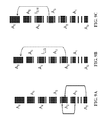
- FIGS. 6A-6C show schematically three separated current flow patterns used to form the current flow pattern of mode 1 shown in FIG. 5A , in accordance with various embodiments.
- FIGS. 7A-7C show schematically three separated current flow patterns of mode 1, applicable for combined software and hardware focusing, in accordance with various embodiments.
- FIGS. 8A-8B show schematically the two separated current flow patterns of mode 1, applicable for combined software and hardware focusing in which a signal of differential voltage is not available for hardware focusing, in accordance with various embodiments.
- FIGS. 9A-9C show schematically three separated current flow patterns to form a current pattern of a mode 2, in accordance with various embodiments.
- FIGS. 10A-10D shows schematically five separated current flow patterns of a mode 3, in accordance with various embodiments.
- FIGS. 11A-E show schematically six separated current flow patterns of a mode 4, in accordance with various embodiments.
- FIG. 12 shows curves demonstrating the borehole effect on apparent resistivity of array laterolog tool when all signals are measurable, in accordance with various embodiments.
- FIG. 13 shows curves demonstrating the borehole effect on apparent resistivity of array laterolog tool when some signals between a pair of monitor electrodes are unreadable, in accordance with various embodiments.
- FIG. 14 shows features of an example method of using a tool to determine resistivity of a formation around a borehole, in accordance with various embodiments.
- FIG. 15 shows features of an example method of using a tool to determine resistivity of a formation around a borehole, in accordance with various embodiments.
- FIG. 16 depicts a block diagram of features of an example system having a tool configured with a main electrode operable with current electrodes and monitor electrodes arranged on the tool with respect to the main electrode, in accordance with various embodiments.
- FIG. 17 depicts an example system at a drilling site, where the system includes a tool configured with a main electrode operable with current electrodes and monitor electrodes arranged on the tool with respect to the main electrode, in accordance with various embodiments.
- the inventors have discovered that if the resistivity contrast between formation resistivity and borehole mud resistivity is too high, some signals acquired in an array laterolog tool can be too small to be measured accurately by direct use of electronics or the signals at different locations are almost identical such as to make the difference between signals indeterminable or lacking in accurate determination. Such situations can render previous methods using an array laterolog tool inaccurate in certain cases with large errors in apparent resistivity output from the measurement.
- a tool having a number of current electrodes spaced apart from each other in a sequence from a main electrode, two monitor electrodes between the main electrode and a first current electrode of the sequence, and two monitor electrodes located next to each other between each of two adjoining current electrodes in the sequence can be operated to determine resistivity of a formation around a borehole.
- Current can be generated from the main electrode and selected ones of the current electrodes according to a selected current pattern.
- Selected monitor electrodes in the sequence can be monitored, voltages at the selected monitor electrodes can be determined, and voltage differences between selected pairs of monitor electrodes can be determined in response to currents generated according to the selected current pattern.
- Apparent resistivity can be determined based on the determined voltages and the determined voltage differences, according to the selected current pattern.
- the tool can be structured as an array laterolog tool.
- An array laterolog tool can be controlled to operate under a modified method for the focusing condition of its components to improve the output results, when some of the signals are too small to be measured accurately.
- This modified method can provide a more stable and robust assessment of the formation resistivity, even when some of the signals are small or unreadable.
- a modified method can include generating currents from the main and one or more current electrodes such that processing of measured signals includes using the currents from the main and the one or more current electrodes as a survey current.
- processing of measured voltages and currents can be conducted with apparent resistivity for each of the operating modes processed being inversely proportional to the current from the main electrode or inversely proportional to the total current emitted from the main electrode and the first current electrode.
- FIG. 1 shows a block diagram of an example embodiment of a system 100 structured to determine resistivity of a formation with respect to a drilling operation associated with borehole 102 .
- the system 100 includes a tool 105 having a tool structure 103 , a control unit 115 , and a data processing unit 120 .
- the tool structure 103 has a main electrode 110 , where the main electrode 110 can be operable with electrodes arranged on the tool structure 103 with respect to the main electrode 110 along a longitudinal axis 117 of the tool structure 103 .
- Monitor electrodes 111 - 1 and 111 - 2 can be arranged on either side of and adjacent to the main electrode 110 .
- the main electrode 110 can be arranged as a central electrode with an upper sequence of electrodes 112 -U- 1 . . . 112 -U-N and monitor electrodes 114 -U- 1 . . . 114 -U-M such that the upper sequence provides a first number of electrodes to one side of the main electrode 110 along the axis 117 .
- the arrangement of main electrode 110 can also include a lower sequence of electrodes 112 -L- 1 . . . 112 -L-N and monitor electrodes 114 -L- 1 . . .
- the upper sequence of the electrodes 112 -U- 1 . . . 112 -U-N and the monitor electrodes 114 -U- 1 . . . 114 -U-N can be arranged such that for each component of the upper sequence there is a component in the lower sequence arranged in substantially the same manner as the component in the upper sequence. In such an arrangement, the upper sequence of the electrodes 112 -U- 1 . . . 112 -U-N and the monitor electrodes 114 -U- 1 . . .
- 114 -U-M is considered to correspond to the lower sequence of the electrodes 112 -L- 1 . . . 112 -L-N and the monitor electrodes 114 -L- 1 . . . 114 -L-M.
- the corresponding electrodes of the upper and the lower sequences can be coupled together. This coupling can be realized as a direct connection or using switches. Switches may also be used to selectively couple monitor electrodes next to each other between two adjoining electrodes of the upper electrodes 12 -U- 1 . . . 112 -U-N and monitor electrodes next to each other between two adjoining electrodes of the lower electrodes 112 -L- 1 . . . 112 -L-N.
- the electrodes 112 -U- 1 . . . 112 -U-N and 112 -L- 1 . . . 112 -L-N can be structured as current electrodes.
- the number of monitor electrodes can be arranged such that voltages are controlled with respect to current generated from the spaced apart electrodes of the main electrode.
- more than one monitor electrode can be associated with a given current electrode.
- Two or more monitor electrodes may be disposed between two adjoining current electrodes.
- the control unit 115 can be structured to operably manage generation and control of a current signal from the main electrode 110 and generation and control of current from the electrodes 112 -U- 1 . . . 112 -U-N and 112 -L- 1 . . . 112 -L-N.
- the control unit 115 can be structured to operably manage measurement of voltages and/or setting voltages of the monitor electrodes 114 -U- 1 . . . 114 -U-M and 114 -L- 1 . . . 114 -L-M.
- the control unit 115 can be structured to selectively generate current from the main electrode 110 and the electrodes 112 -U- 1 . . .
- the control unit 115 can be structured to selectively generate current and/or set reference potentials such that measured voltages and generated currents can be used to determine resistivity.
- the data processing unit 120 of the system 100 can be structured to process the measured voltages with respect to the generated currents to determine formation resistivity.
- the data processing unit 120 can be realized as a processing unit with a controller, such as a processor, with a data storage device such that values of measured voltages and generated currents can be processed to provide resistivity data.
- the tool 105 can be structured with the data processing unit 120 and the control unit 115 both integrated with the tool structure 103 or structured as distributed components.
- the control unit 115 can be structured to selectively control the first number of the electrodes 112 -U- 1 . . . 112 -U-N and the second number of the electrodes 112 -L- 1 . . . 112 -L-N such that selected ones of the first number of electrodes and of the second number of electrodes receive current from the main electrode 110 or other electrode in the same respective sequence.
- the control unit 115 can be arranged to generate current from other selected ones of the first number of electrodes and the second number of electrodes based on a selected current pattern.
- the control unit 115 can be arranged to adjust the current such that a potential difference between selected ones of the monitored electrodes equals a reference potential.
- Reference structures 113 -U and 113 -L may provide a reference with which to measure voltages. Other reference structures can be used.
- the control unit 115 can be arranged to selectively control the main electrode 110 , the first number of electrodes 112 -U- 1 . . . 112 -U-N, and the second number of electrodes 112 -L- 1 . . . 112 -L-N to generate a current pattern.
- the control unit 115 can also include circuitry to process signals acquired that the monitor electrodes 114 -U- 1 . . . 114 -U-M and 114 -L- 1 . . . 114 -L-M. Such circuitry can include filters to distinguish signals at different frequencies correlated to currents generated at assigned frequencies. Alternatively, such signal processing can be conducted in the data processing unit 120 or in a combination of the control unit 115 and the data processing unit 120 .
- FIG. 2 shows a configuration of an embodiment of electrodes of an array laterolog tool 205 .
- the electrodes can include a main electrode A 0 that functions as a survey electrode, current emitting electrodes A 1 , A 2 , . . . , A N and current emitting electrodes A 1 ′, A 2 ′, . . . , A N ′ disposed on opposite sides with respect of A 0 , and voltage monitoring electrodes M 1 , . . . , M 2*(N-1) , and M 1 ′, . . . , M 2*(N-1) ′ disposed on opposite sides with respect of A 0 .
- Each current electrode A i and A i ′ can be arranged with two monitor electrodes M j and M j+1 and M j ′ and M j+1 ′, respectively, with M j and M j+1 on opposite sides of A i (M j ′ and M j+1 ′ on opposite sides of A i ′).
- This arrangement can include monitoring electrodes located next to each other between two adjoining current electrodes.
- the electrodes A 1 , A 2 , . . . , A N and the electrodes A 1 ′, A 2 ′, . . . , A N ′ can be symmetrically disposed with respect to A 0 .
- Electrodes A k and A k ′ can be of different sizes.
- FIG. 3 shows another view of an array laterolog 305 that can be used in systems and methods discussed herein.
- FIG. 4A shows a current flow pattern with associated frequencies.
- the current flows are schematically depicted for half of the current electrodes (electrodes A 1 , A 2 , . . . , A N ) and the survey electrode A 0 of the array laterolog tool 205 of FIG. 2 in a software focusing method. Similar flows are provided in the other half of the current electrodes (electrodes A 1 ′, A 2 ′, . . . , A N ′) and the survey electrode A 0 .
- electrodes A 1 ′, A 2 ′, . . . , A N ′ the survey electrode A 0 .
- FIG. 4B shows another current flow pattern with its associated frequencies.
- the current flows are schematically depicted for half the electrodes of the array laterolog tool 205 in a combination hardware/software focusing method.
- Focusing refers to providing a balance in the measurement procedure, which can be satisfied by setting potentials at selected ones of electrodes equal to selected values, while having other selected ones of electrodes disconnected from being in a current circuit.
- Software focusing method refers to generating current from the array laterolog tool and measuring potentials without potentials at selected electrodes set equal and using linearity of the measuring environment to determine the quantities being measured from known relationships between current and potential in the measuring environment.
- Hardware focusing method refers to generating current from an array laterolog tool and measuring potentials with potentials at selected electrodes set equal.
- Combination hardware/software focusing method refers to using at least one measurement in the measurement procedure by a hardware focusing method with the other measurements made using the software focusing method.
- FIG. 4B Comparing FIG. 4A , it is seen that the difference between the combination focusing method and the software focusing method is that the combination focusing method the survey electrode A 0 emits two currents with different frequencies, f 0 and f 1 .
- two sets of data can be measured.
- the first set is the potential on the monitor electrodes with odd order or even order measured with respect to a reference electrode. Though one of the sets, odd order or even order, can be used for determining formation resistivity, both can be measured to improve accuracy and to add redundancy.
- the potentials of the monitoring electrodes are functions of the measuring time, t, and can be expressed as
- N is the number of current electrodes in one-half of the tool
- N ⁇ 1 refers to the other electrodes except the last electrode, UM i,f k is the amplitude of the potential, or the voltage, with frequency f k at the i th monitoring electrode, t is the measuring time for each logging position, ⁇ i,k is the initial phase with respect to frequency f k on the i th monitor.
- the second set which can be measured, are the voltage differences between monitoring electrodes located next to each other between two adjoining current electrodes. These voltage differences are functions of the measuring time, t, and can be expressed as
- ⁇ VM i,i+1,f k is the amplitude of the voltage with frequency f k between i th and (i+1) th monitor electrodes
- ⁇ i,i+1,k is the initial phase of ⁇ VM i,i+1,f k with frequency f k .
- the amplitude of the voltages and voltage differences can be processed and expressed as
- the current emitted by A 0 through A N-1 can be recorded in a memory device, for example, and labeled as I 0,f 0 , I 1,f 1 , . . . , I (N-1),f N-1 for software focusing method and I 0,f 0 , I 0,f 1 , I 1,f 1 , . . . , I (N-1),f N-1 for combination software/hardware focusing method.
- the array laterolog tool 205 of FIG. 2 or a similar array laterolog tool can be operated to make the measurements described above that can be used to synthesize N ⁇ 1 operational modes with the depth of investigation (DOI).
- DOI can be defined in terms of radius.
- Mode ⁇ ⁇ 1 k 1 ⁇ UM 1 I 0 , where UM 1 is the voltage between the monitor electrode M and the reference electrode, and I 0 is the total current emitted by the electrode A0, when operation mode 1 is satisfied with respect to the monitor electrodes and the current flow.
- the factor k 1 is the tool's coefficient for mode 1.
- the currents emitted by A 0 , A 1 , and A 2 only flow into A 3 , while keeping the voltage difference between the monitoring electrodes M 1 and M 2 , ⁇ VM 1,2 , and the voltage difference between the monitoring electrodes M 3 and M 4 , ⁇ VM 3,4 , at 0 volts.
- the apparent resistivity can be computed as
- Mode ⁇ ⁇ 2 k 2 ⁇ UM 1 I 0 , where UM 1 is the voltage between the monitor electrode M1 and the reference electrode, and I 0 is the total current emitted by the electrode A0 when operation mode 2 is satisfied with respect to the monitor electrodes and the current flow.
- the factor k 2 is the tool's coefficient of mode 2.
- the currents emitted by A 0 , A 1 , A 2 , and A 3 only flow into A 4 , while keeping the voltage difference between the monitoring electrodes M 1 and M 2 , ⁇ VM 1,2 , the voltage difference between the monitoring electrodes M 3 and M 4 , ⁇ VM 3,4 , and the voltage difference between the monitoring electrodes M 5 and M 6 , ⁇ VM 5,6 , at 0 volts.
- the apparent resistivity can be computed as
- Mode ⁇ ⁇ 3 k 3 ⁇ UM 1 I 0 , where UM 1 is the voltage between the monitor electrode M1 and the reference electrode, and I 0 is the total current emitted by the electrode A0 when operation mode 3 is satisfied with respect to the monitor electrodes and the current flow.
- the factor k 3 is the tool's coefficient of mode 3.
- the currents emitted by A 0 , A 1 , A 2 , A 3 , and A 4 only flow into A 5 , while keeping the voltage difference between the monitoring electrodes M 1 and M 2 , ⁇ VM 1,2 , the voltage difference between the monitoring electrodes M 3 and M 4 , ⁇ VM 3,4 , the voltage difference between the monitoring electrodes M 5 and M 6 , ⁇ VM 5,6 , and the voltage difference between the monitoring electrodes M 7 and M 8 , ⁇ VM 7,8 , at 0 volts.
- the apparent resistivity can be computed as
- Mode ⁇ ⁇ 4 k 4 ⁇ UM 1 I 0 , where UM 1 is the voltage between the monitor electrode M1 and the reference electrode, and I 0 is the total current emitted by the electrode A 0 when operation mode 4 is satisfied with respect to the monitor electrodes and the current flow.
- the factor k 4 is the tool's coefficient of mode 4.
- the currents emitted by A 0 , A 1 , A 2 , A 3 , A 4 and A 5 only flow into A 6 , while keeping the voltage difference between the monitoring electrodes M 1 and M 2 , ⁇ VM 1,2 , the voltage difference between the monitoring electrodes M 3 and M 4 , ⁇ VM 3,4 , the voltage difference between the monitoring electrodes M 5 and M 6 , ⁇ VM 5,6 , the voltage difference between monitoring the electrodes M 7 and M 8 , ⁇ VM 7,8 , and the voltage difference between the monitoring electrodes M 9 and M 10 , ⁇ VM 9,10 , at 0 volts.
- the apparent resistivity can be computed as
- Mode ⁇ ⁇ 5 k 5 ⁇ UM 1 I 0 , where UM 1 is the voltage between the monitor electrode M1 and the reference electrode, and I 0 is the total current emitted by the electrode A0 when operation mode 5 is satisfied with respect to the monitor electrodes and the current flow.
- the factor k 5 is the tool's coefficient of mode 5.
- Table 1 shows an example of simulated signals at an array laterolog tool in a formation.
- the model for the formation has a borehole size of 8 inches, a formation resistivity, R t , of 20,000 ohm-m and a mud resistivity, R m , of 0.02 ohm-m, providing the ratio 1,000,000:1.
- the currents I f0 , I f1 , I f2 , I f3 , I f4 and I f5 are 0.1(A). If some voltage difference between M1 and M2 are not readable, such as data shown in Tables 2 and 3, the software focusing method does not work. In Table 2, the voltage difference between M1 and M2 for frequencies f 3 , f 4 , and f 5 can be neglected. In Table 3, the voltage difference between M1 and M2 for frequencies f 2 , f 3 , f 4 , and f 5 can be neglected.
- Mode ⁇ ⁇ 1 k 1 ⁇ UM 1 I 0 , where UM 1 is the voltage between the monitor electrode M 1 and the reference electrode.
- I 0 is the current emitted by the electrode A0 with frequency f 1 if the measured data is like that shown in Table 3, where the voltage difference between M 1 and M 2 for frequencies f 2 , f 3 , f 4 , and f 5 can be neglected, when operation mode 1 is satisfied.
- I 0 is the total current emitted by electrode A0 with frequencies f 0 and f 1 if the measured signals are like that shown in Table 2, where the voltage difference between M 1 and M 2 for frequencies f 3 , f 4 , and f 5 can be neglected.
- the factor k 1 is the tool's coefficient of mode 1.
- the electrodes A 0 , A 1 , and A 1 ′ can be taken to be combined together to be a survey electrode with the total current emitted by A 0 , A 1 , and A 1 ′, expressed by I model , kept as survey current.
- the currents emitted by A 0 , A 1 and A 2 flow into A3, while keeping the voltage differences between the monitoring electrodes M 3 and M 4 , ⁇ VM 3,4 , at 0 volts.
- the apparent resistivity for mode 2 can be computed as
- Mode ⁇ ⁇ 2 k 2 ⁇ UM 1 I mode ⁇ ⁇ 1 , where UM 1 is the voltage between the monitor electrode M 1 and the reference electrode with I model being the total current emitted by A 0 , A 1 , and A 1 ′.
- the factor k 2 is the tool's coefficient of mode 2.
- the currents emitted by A 0 , A 1 , A 2 , and A 3 only flow into A 4 , while keeping the voltage differences between monitoring electrodes M 3 and M 4 , ⁇ VM 3,4 , and the voltage differences between monitoring electrodes M 5 and M 6 , ⁇ VM 5,6 , at 0 volts.
- the apparent resistivity for mode 3 can be computed as
- Mode ⁇ ⁇ 3 k 3 ⁇ UM 1 I mode ⁇ ⁇ 1 , where UM 1 is the voltage between the monitor electrode M 1 and the reference electrode with I model being the total current emitted by A 0 , A 1 , and A 1 ′.
- the factor k 3 is the tool's coefficient of mode 3.
- the currents emitted by A 0 , A 1 , A 2 , A 3 , and A 4 only flow into A 5 , while keeping the voltage differences between monitoring electrodes M 3 and M 4 , ⁇ VM 3.4 , the voltage differences between monitoring electrodes M 5 and M 6 , ⁇ VM 5,6 , and the voltage differences between monitoring electrodes M 7 and M 8 , ⁇ VM 7,8 , at 0 volts.
- the apparent resistivity for mode 4 can be computed as
- Mode ⁇ ⁇ 4 k 4 ⁇ UM 1 I mode ⁇ ⁇ 1 , where UM 1 is the voltage between the monitor electrode M 1 and the reference electrode with I model being the total current emitted by A 0 , A 1 , and A 1 ′.
- the factor k 4 is the tool's coefficient of mode 4.
- the currents emitted by A 0 , A 1 , A 2 , A 3 , A 4 , and A 5 flow into A 6 , while keeping the voltage differences between monitoring electrodes M 3 and M 4 , ⁇ VM 3,4 , the voltage differences between monitoring electrodes M 5 and M 6 , ⁇ VM 5,6 , the voltage differences between monitoring electrodes M 7 and M 8 , ⁇ VM 7,8 , and the voltage differences between monitoring electrodes M 9 and M 10 , ⁇ VM 9,10 , at 0 volts.
- the apparent resistivity for mode 5 can be computed as
- Mode ⁇ ⁇ 5 k 5 ⁇ UM 1 I mode ⁇ ⁇ 1 , where UM 1 is the voltage between the monitor electrode M 1 and the reference electrode with I model being the total current emitted by A 0 , A 1 , and A 1 ′.
- the factor k 5 is the tool's coefficient of mode 5.
- a software focusing methodology can be implemented to compute apparent resistivity when the small signals between the monitor electrodes M1 and M2 are not readable.
- survey electrode A 0 only emits one current with frequency f 0 , as shown in FIG. 4A .
- FIGS. 6A-C shows schematically three separated current flow patterns used to form the current flow pattern of mode 1 shown in FIG. 5A .
- FIGS. 6A, 6B, and 6C represent the currents emitted by A 0 , A 1 , and A 2 flowing to A 6 , respectively.
- the operation of mode 1 can be realized by following conditions.
- I 2,f 3 T ⁇ ( I 0,f1 T +I 1,f 2 T ), (4) where I 0,f1 T , I 1,f 2 T , and I 2,f 3 T represent the total current emitted by A 0 , A l , and A 2 flowing to A 6 , respectively, when the balance of mode 1 operation is satisfied.
- the operation of mode 1 is balanced when the voltages of monitor electrodes M 1 and M 2 are equal or a voltage imbalance is removed by processing of signals to provide the focusing conditions.
- FIGS. 7A-C show schematically the three separated current flow patterns of mode i, applicable for combined software and hardware focusing in which a signal of differential voltage between M 1 and M 2 of frequency f 2 is readable.
- FIG. 7A represents hardware focusing
- FIGS. 7B and 7C represent the current emitted by A 0 and A 2 flowing to A 6 , respectively.
- FIGS. 8A-B show schematically the two separated current flow patterns of mode 1, applicable for combined software and hardware focusing without in a signal of differential voltage between M 1 and M 2 ( ⁇ V 1,2 signal). In this method, signals of differential voltage between M 1 and M 2 are not readable for all frequencies.
- FIG. 8A represents hardware focusing
- FIG. 8B represents the current emitted by A 2 flowing to A 6 .
- the operation of mode 1 can be realized by the following processing.
- I 2,f 2 T ⁇ ( I 0,f 1 +I 1,f 1 ), (14) where I 0,f 1 and I 1,f 1 represent the current emitted by A 0 , A 1 flowing to A 6 , respectively, and I 2,f 2 T is the total current emitted by A 2 flowing into A 6 .
- FIGS. 9A-C show schematically three separated current flow patterns to form a current pattern of mode 2.
- FIG. 9A represents a current flow pattern of mode 1
- FIGS. 8B and 8C represent the current emitted by A 2 and A 3 flowing to A 6 , respectively.
- FIGS. 10A-D shows schematically four separated current flow patterns of mode 3.
- FIG. 10A represents current flow pattern of mode 1
- FIGS. 10B, 10C and 10D represent the current emitted by A 2 , A 3 , and A 4 flowing to A 6 , respectively.
- FIGS. 11A-E show schematically five separated current flow patterns of mode 4.
- FIG. 11A represents a current flow pattern of mode 1
- FIGS. 11B, 11C, 11D, and 11E represent the current emitted by A 0 , A 2 , A 3 , A 4 , and A 5 flowing to A 6 , respectively.
- Mode 5 of operation can be realized by combining the measurements of FIGS. 11A-E using a set of constraints.
- the apparent resistivity of mode 5 can be computed by the following formula,
- FIG. 12 shows curves demonstrating the borehole effect on apparent resistivity of array laterolog tool when all signals are measurable.
- FIG. 13 shows curves demonstrating the borehole effect on apparent resistivity of array laterolog tool when some signals between M 1 and M 2 are unreadable such as when the measured data is like that shown in Table 2.
- Both figures show a plot of the ratio of corrected resistance to apparent resistance as a function of the ratio of the apparent resistance to mud resistance.
- the apparent resistance is the apparent resistance from mode 5.
- the apparent resistance is the apparent resistance from mode 1.
- the apparent resistance is the apparent resistance from mode 2.
- the apparent resistance is the apparent resistance from mode 3.
- the apparent resistance is the apparent resistance from mode 4.
- Comparison of FIGS. 12 and 13 indicates that different look up tables are to be used to perform borehole correction when some signals are not readable.
- a software focusing methodology as described herein can be used to compute apparent resistivity of array laterolog tool when some signals are too small to be measured. Such processing may offer more stable array laterolog measurements that may offer more accurate and stable apparent formation resistivity, in high contrast cases between formation resistivity and mud resistivity.
- FIG. 14 shows features of an embodiment of an example method of using a tool to determine resistivity of a formation around a borehole.
- current from a main electrode of a tool disposed in a borehole is generated.
- the current from the main electrode can be generated at an assigned frequency.
- the tool can have a number of current electrodes spaced apart from each other in a sequence from the main electrode and can have two monitor electrodes between the main electrode and a first current electrode of the sequence and two monitor electrodes located next to each other between each of two adjoining current electrodes in the sequence.
- the current can be generated as a current from the main electrode to the last current electrode in the sequence.
- the tool can include additional current electrodes and monitor electrodes arranged in a sequence from the main electrode in a manner similar to or identical to the above-mentioned sequence but in an opposite direction from the main electrode.
- the two sequences of current electrodes and monitor electrodes can be arranged symmetrically with each other relative to the main electrode.
- current from each one of the current electrodes in the sequence is generated to the last current electrode in the sequence at a frequency assigned to the current electrode.
- the assigned frequencies can be different from each other.
- the current generated from the main electrode and current electrodes can be generated such that theses currents only flow into the last current electrode.
- an additional current can be generated from the main electrode to the last current electrode with the two monitor electrodes between the main electrode and the first current electrode physically set to substantially the same voltage, where the additional current can be at a frequency different from the frequency of the current from the main electrode.
- the frequency of the additional current can be set at the assigned frequency of the first current electrode.
- voltages at the monitor electrodes are determined in response to the currents generated from the current electrodes in the sequence.
- voltage differences between two monitor electrodes located next to each other between each of two adjoining current electrodes in the sequence is determined in response to the currents generated.
- the voltage differences between two monitor electrodes located between the main electrode and the first current electrode can be determined.
- the voltage differences at the different frequencies can be measured directly using electronic circuitry of a control unit, a data processing unit, or a combination of a control unit and data processing unit.
- differences between the voltages measured at the monitor voltages can be determined, where the voltages at the monitor voltages are measured with respect to a reference. Filtering can be used to distinguish the frequency components.
- the measured quantities UM i (t) and ⁇ VM i,i+1 (t) can be represented as a sum of components by superposition, with each component representing a single frequency.
- . . N ⁇ 1 refers to the current electrodes in the sequence except the last electrode, UM i,f k is an amplitude of the voltage with frequency f k at the i th monitoring electrode, t is measuring time for each logging position, ⁇ i,k is initial phase with respect to frequency f k on the i th monitor, ⁇ VM i,i+1,f k is an amplitude of the voltage with frequency f k between i th and (i+1) th monitor electrodes, and ⁇ i,i+1,k is the initial phase of ⁇ VM i,i+1,f k with frequency f k .
- the relationships can be processed, for example using one or processors and data storage devices, determining each UM i,f k , ⁇ i,k , ⁇ VM i,i+1,f k , and ⁇ i,i+1,k .
- the measuring time t can be discrete. Processing can include using a fast Fourier transform or a least-square method on data and relationships corresponding to the discrete times.
- the currents, I k,f k emitted by the main electrode and the current electrodes, other than the last electrode, can be recorded as I 0,f 0 , I 1,f 1 , . . . , I (N-1),f N-1 in a memory device.
- Processing can include balancing the two monitor electrodes between the main electrode and a first current electrode such that voltage imbalance is removed by processing of signals to provide a focusing condition.
- I 0,f 1 being an additional current generated from the main electrode to the last current electrode with the two monitor electrodes between the main electrode and the first current electrode physically set to substantially the same voltage
- currents emitted by the main electrode and the current electrodes, other than the last electrode can be recorded as I 0,f 0 , I 0,f 1 , I 1,f 1 , . . . , I (N-1),f N-1 in a memory device.
- the additional current can be at the frequency of the current from the first current electrode.
- an apparent resistivity based on the determined voltages and the determined voltage differences is determined.
- FIG. 15 shows features of an embodiment of an example method of using a tool to determine resistivity of a formation around a borehole.
- a tool disposed in a borehole is operated according to a plurality of modes. Each mode can correspond to a current pattern emitted from the tool.
- the tool can have a number of current electrodes spaced apart from each other in a first sequence from a main electrode and a number of current electrodes spaced apart from each other in a second sequence from the main electrode, two monitor electrodes between the main electrode and a first current electrode of the first sequence, two monitor electrodes between the main electrode and a first current electrode of the second sequence, and two monitor electrodes located next to each other between each of two adjoining current electrodes in the first sequence and in the second sequence.
- the two monitor electrodes between the main electrode and the first current electrode of the first sequence can be set to equal voltages by processing signals to provide focusing conditions of the respective mode, and the two monitor electrodes between selected current electrodes of the first sequence with respect to the respective mode can be set to equal voltages by processing signals to provide focusing conditions of the respective mode, using linearity of measuring environment to determine the quantities being measured from known relationships between current and potential in the measuring environment (software processing).
- the two monitor electrodes between the main electrode and the first current electrode of the first sequence or the two monitor electrodes between selected adjoining current electrodes of the first sequence can be set to equal voltages by adjusting one or more currents flowing from the tool.
- the two monitor electrodes between the main electrode and the first current electrode of the first sequence can be set to equal voltages by the adjustment. This setting of balance among selected monitor electrodes can be conducted as hardware processing or a combination of hardware and software processing.
- voltages measured from monitor electrodes of the first sequence, readable voltage differences measured between the two monitor electrodes between the two adjoining current electrodes of the first sequence, and measured currents at a plurality of frequencies are processed according to each mode.
- the electrodes of the first sequence and the electrodes of the second sequence may be operated in a similar or an identical manner.
- an approach to focusing an array laterolog can include using a survey current from the main electrode and an effective survey current taken as a sum of the current from the main electrode and one or more current electrodes.
- the current emitted from the main electrode of the first mode can be emitted at a first frequency and the total current emitted from the main electrode, the first current electrode of the first sequence, and the first current electrode of the second sequence can be used as a first mode current equal to the sum of the current emitted from the main electrode at the first frequency and current from the first current electrodes of the first and second sequences at the first frequency.
- the first mode current can be used to determine coefficients that relate total voltages at the two monitor electrodes between the main electrode and the first current electrode of the first sequence to voltages at the two monitor electrodes between the main electrode and the first current electrode of the first sequence at the frequencies of the respective mode.
- the processing can be conducted such that an apparent resistivity of a first mode of the plurality of modes can be processed as being inversely proportional to a current emitted from the main electrode and an apparent resistivity for each of the other modes can be processed as being as being inversely proportional to a total current including total current emitted from the main electrode, the first current electrode of the first sequence, and the first current electrode of the second sequence.
- the total current can include current from other components in addition to the total current emitted from the main electrode, the first current electrode of the first sequence, and the first current electrode of the second sequence.
- a tool such as one used in methods associated with FIG. 14 or FIG. 15 can be directed to operation by an electronic system using instructions physically stored in device.
- a machine-readable storage device can have instructions stored thereon, which, when performed by a machine, cause the machine to perform operations, where the operations comprises features similar or identical to those discussed with respect to FIGS. 14 and 15 .
- a system can be structured such that its operations include features similar or identical to those discussed with respect to FIGS. 14 and 15 .
- Such a system can comprise a tool operable in a borehole, the tool having a number of current electrodes spaced apart from each other in a sequence from a main electrode, the tool having two monitor electrodes between the main electrode and a first current electrode of the sequence and two monitor electrodes located next to each other between each of two adjoining current electrodes in the sequence; a control unit coupled to the tool, the control unit having circuitry to control generation of currents from the tool according to a plurality of modes, each mode corresponding to a current pattern emitted from the tool; and a processing unit coupled to the tool.
- the control unit and the processing unit can be arranged as an integrated unit.
- Various components of a system including a tool having a main electrode; having a first number of electrodes to one side of the main electrode along the axis and a second number of electrodes on another side of the main electrode along the axis; and having a number of monitor electrodes to monitor signals with respect to current generated from the main electrode, the first number of electrodes, and the second number of electrodes, as described herein or in a similar manner, may be realized in combinations of hardware and software based implementations.
- implementations may include a machine-readable storage device having machine-executable instructions, such as a computer-readable storage device having computer-executable instructions, to generate current from a main electrode of a tool disposed in a borehole at a frequency assigned to the main electrode, the tool having a number of current electrodes spaced apart from each other in a sequence from the main electrode, the tool having two monitor electrodes between the main electrode and a first current electrode of the sequence and two monitor electrodes located next to each other between each of two adjoining current electrodes in the sequence; to generate current from each one of the current electrodes in the sequence to a last current electrode in the sequence at a frequency assigned to the current electrode, the assigned frequencies being different from each other; to determine voltages at the monitor electrodes in response to the currents generated from the current electrodes in the sequence; to determine voltage differences between the two monitor electrodes located next to each other between each of two adjoining current electrodes in the sequence in response to the currents generated; and to determine an apparent resistivity based on the determined voltages and the determined voltage differences
- these implementations may include a machine-readable storage device having machine-executable instructions, such as a computer-readable storage device having computer-executable instructions, to operate a tool disposed in a borehole according to a plurality of modes, each mode corresponding to a current pattern emitted from the tool, the tool having a number of current electrodes spaced apart from each other in a first sequence from a main electrode and a number of current electrodes spaced apart from each other in a second sequence from the main electrode, the tool having two monitor electrodes between the main electrode and a first current electrode of the first sequence, two monitor electrodes between the main electrode and a first current electrode of the second sequence, and two monitor electrodes located next to each other between each of two adjoining current electrodes in the first sequence and in the second sequence: and to process voltages measured from the monitor electrodes of the first sequence, readable voltage differences measured between the two monitor electrodes between the two adjoining current electrodes of the first sequence, and measured currents at a plurality of frequencies according to each
- the instructions can include instructions to operate the first sequence and second sequence in a similar or an identical manner.
- the instructions can include instructions to manage the tool, determine formation resistivities, and direct drilling operations, such as but not limited to steering operations, based on the results of using the determined resistivities, in accordance with the teachings herein.
- a machine-readable storage device herein, is a physical device that stores data represented by physical structure within the device. Examples of machine-readable storage devices include, but are not limited to, read only memory (ROM), random access memory (RAM), a magnetic disk storage device, an optical storage device, a flash memory, and other electronic, magnetic, and/or optical memory devices.
- FIG. 16 depicts a block diagram of features of an example embodiment of a system 1600 having a tool 1605 including a main electrode 1610 operable with electrodes 1612 and 1614 arranged on the tool 1605 with respect to the main electrode 1610 along a longitudinal axis of the tool 1605 .
- the system 1600 includes the tool 1605 having an arrangement of a main electrode 1610 , current electrodes 1612 , and monitor electrodes 1614 that can be realized in a similar or identical manner to arrangements of electrodes discussed herein.
- the system 1600 can be configured to operate in accordance with the teachings herein.
- the system 1600 can include a controller 1625 , a memory 1630 , an electronic apparatus 1665 , and a communications unit 1635 .
- the controller 1625 , the memory 1630 , and the communications unit 1635 can be arranged to operate as a processing unit to control operation of the tool 1605 , having an arrangement of the main electrode 1610 , the current electrodes 1612 , and the monitor electrodes 1614 to perform measurements in a borehole from which formation resistivity can be determined and management of a drilling operation can be conducted, in a manner similar or identical to the procedures discussed herein.
- Such a processing unit can be realized using a data processing unit 1620 , which can be implemented as a single unit or distributed among the components of the system 1600 including the electronic apparatus 1665 .
- the controller 1625 and the memory 1630 can operate to control activation of the main electrode 1610 and the current electrodes 1612 and selection of the monitor electrodes 1614 in the tool 1605 and to manage processing schemes in accordance with measurement procedures and signal processing as described herein.
- Generation of current between the main electrode 1610 and the current electrodes 1612 can be conducted using current generator(s) 1607 .
- the current generator(s) 1607 can provide a reference current of the main electrode 1610 .
- the current from the main electrode 1610 and selected ones of the current electrodes 1612 may depend on the current path and homogeneity status of the formation material of the current path.
- Selection of particular current electrodes and focusing of current to selected current electrodes may be realized using voltage generator(s) 1608 and switch(es) 1609 in addition to the current generator(s) 1607 .
- the system 1600 can be structured to function in a manner similar to or identical to structures associated with FIGS. 1-13 .
- the communications unit 1635 can include downhole communications for appropriately located electrodes. Such downhole communications can include a telemetry system.
- the communications unit 1635 may use combinations of wired communication technologies and wireless technologies at frequencies that do not interfere with on-going measurements.
- the system 1600 can also include a bus 1627 , where the bus 1627 provides electrical conductivity among the components of the system 1600 .
- the bus 1627 can include an address bus, a data bus, and a control bus, each independently configured or in an integrated format.
- the bus 1627 can be realized using a number of different communication mediums that allows for the distribution of components of the system 1600 . Use of the bus 1627 can be regulated by the controller 1625 .
- the peripheral devices 1645 can include additional storage memory and/or other control devices that may operate in conjunction with the controller 1625 and/or the memory 1630 .
- the controller 1625 can be realized as a processor or a group of processors that may operate independently depending on an assigned function.
- the peripheral devices 1645 can be arranged with one or more displays 1655 , as a distributed component on the surface, that can be used with instructions stored in the memory 1630 to implement a user interface to monitor the operation of the tool 1605 and/or components distributed within the system 1600 .
- the user interface can be used to input operating parameter values such that the system 1600 can operate autonomously substantially without user intervention.
- FIG. 17 depicts an embodiment of a system 1700 at a drilling site, where the system 1700 includes a tool 1705 configured with a main electrode operable with electrodes arranged on the tool with respect to the main electrode along a longitudinal axis of the tool 1705 .
- the tool 1705 can be realized in a similar or identical manner to arrangements of electrodes discussed herein and can be configured to operate in accordance with the teachings herein.
- the system 1700 can be arranged in a land based drilling operation or a subsea drilling operation.
- the system 1700 can include a drilling rig 1702 located at a surface 1704 of a well 1706 and a string of drill pipes, that is, the drill string 1708 , connected together so as to form a drilling string that is lowered through a rotary table 1707 into a wellbore or borehole 1712 .
- the drilling rig 1702 can provide support for the drill string 1708 .
- the drill string 1708 can operate to penetrate rotary table 1707 for drilling a borehole 1712 through subsurface formations 1714 .
- the drill string 1708 can include drill pipe 1718 and a bottom hole assembly 1720 located at the lower portion of the drill pipe 1718 .
- the bottom hole assembly 1720 can include drill collar 1715 , the tool 1705 attached to the drill collar 1715 , and a drill bit 1726 .
- the drill bit 1726 can operate to create the borehole 1712 by penetrating the surface 1704 and the subsurface formations 1714 .
- the tool 1705 can be structured for an implementation in the borehole 1712 of a well as a measurements-while-drilling (MWD) system such as a logging-while-drilling (LWD) system to determine formation resistivity, which can be used to direct drilling operations based on the determined resistivity.
- the housing containing the tool 1705 can include electronics to activate electrodes of the tool 1705 and collect responses from electrodes of the tool 1705 .
- Such electronics can include a data processing unit to analyze signals received by the tool 1705 and provide measurement results of resistivity to the surface over a standard communication mechanism for operating a well.
- electronics can include a communications interface to provide signals measured by the tool 1705 to the surface over a standard communication mechanism for operating a well, where these measured signals can be analyzed at a processing unit at the surface.
- the drill string 1708 can be rotated by the rotary table 1707 .
- the bottom hole assembly 1720 can also be rotated by a motor (e.g., a mud motor) that is located downhole.
- the drill collars 1715 can be used to add weight to the drill bit 1726 .
- the drill collars 1715 also can stiffen the bottom hole assembly 1720 to allow the bottom hole assembly 1720 to transfer the added weight to the drill bit 1726 , and in turn, assist the drill bit 1726 in penetrating the surface 1704 and subsurface formations 1714 .
- a mud pump 1732 can pump drilling fluid (sometimes known by those of skill in the art as “drilling mud”) from a mud pit 1734 through a hose 1736 into the drill pipe 1718 and down to the drill bit 1726 .
- the drilling fluid can flow out from the drill bit 1726 and be returned to the surface 1704 through an annular area 1740 between the drill pipe 1718 and the sides of the borehole 1712 .
- the drilling fluid may then be returned to the mud pit 1734 , where such fluid is filtered.
- the drilling fluid can be used to cool the drill bit 1726 , as well as to provide lubrication for the drill bit 1726 during drilling operations. Additionally, the drilling fluid may be used to remove the subsurface formation 1714 cuttings created by operating the drill bit 1726 .
- the tool 1705 may be included in a tool body 1770 coupled to a logging cable 1774 such as, for example, for wireline applications.
- the tool body 1770 containing the tool 1705 can include electronics to activate electrodes of the tool 1705 and collect responses from electrodes of the tool 1705 .
- Such electronics can include a data processing unit to analyze signals measured by the tool 1705 and provide measurement results of resistivity to the surface over a standard communication mechanism for operating a well.
- electronics can include a communications interface to provide signals measured by the tool 1705 to the surface over a standard communication mechanism for operating a well, where these collected measurement signals are analyzed at a processing unit at the surface.
- the logging cable 1774 may be realized as a wireline (multiple power and communication lines), a mono-cable (a single conductor), and/or a slick-line (no conductors for power or communications), or other appropriate structure for use in the bore hole 1712 .
- the tool body 1770 can be used in the same borehole 1712 as the bottom hole assembly 1720 .
Landscapes
- Life Sciences & Earth Sciences (AREA)
- Engineering & Computer Science (AREA)
- Environmental & Geological Engineering (AREA)
- Geology (AREA)
- Remote Sensing (AREA)
- Physics & Mathematics (AREA)
- General Life Sciences & Earth Sciences (AREA)
- General Physics & Mathematics (AREA)
- Geophysics (AREA)
- Measurement Of Resistance Or Impedance (AREA)
- Geophysics And Detection Of Objects (AREA)
- Investigating Or Analyzing Materials By The Use Of Electric Means (AREA)
Abstract
Description
where N is the number of current electrodes in one-half of the tool, k=0 refers to the main electrode and k=1, . . . , N−1 refers to the other electrodes except the last electrode, UMi,f
where ΔVMi,i+1,f
The current emitted by A0 through AN-1 can be recorded in a memory device, for example, and labeled as I0,f
where UM1 is the voltage between the monitor electrode M and the reference electrode, and I0 is the total current emitted by the electrode A0, when
where UM1 is the voltage between the monitor electrode M1 and the reference electrode, and I0 is the total current emitted by the electrode A0 when
where UM1 is the voltage between the monitor electrode M1 and the reference electrode, and I0 is the total current emitted by the electrode A0 when
where UM1 is the voltage between the monitor electrode M1 and the reference electrode, and I0 is the total current emitted by the electrode A0 when
where UM1 is the voltage between the monitor electrode M1 and the reference electrode, and I0 is the total current emitted by the electrode A0 when
| TABLE 1 | ||||||
| ΔVM1, 2 | ΔVM3, 4 | ΔVM5, 6 | ΔVM7, 8 | ΔVM9, 10 | ||
| f0 | 0.0019048 | 0.003942104 | 0.008902 | 0.0148319 | 0.017776 |
| |
0 | 0.003941374 | 0.008902 | 0.0148314 | 0.0177753 |
| f2 | −3.696E−08 | −4.8342E−07 | 0.008903 | 0.0148321 | 0.0177762 |
| f3 | −2.876E−08 | −2.4775E−07 | −9.09E−07 | 0.0148315 | 0.0177766 |
| f4 | −1.883E−08 | −1.6181E−07 | −6.5E−07 | −1.5E−06 | 0.0177773 |
| f5 | −8.54E−09 | −7.329E−08 | −3E−07 | −8.1E−07 | −1.5E−06 |
| TABLE 2 | ||||||
| ΔVM1, 2 | ΔVM3, 4 | ΔVM5, 6 | ΔVM7, 8 | ΔVM9, 10 | ||
| f0 | 0.0019048 | 0.003942104 | 0.008902 | 0.0148319 | 0.017776 |
| |
0 | 0.003941374 | 0.008902 | 0.0148314 | 0.0177753 |
| f2 | −3.696E−08 | −4.8342E−07 | 0.008903 | 0.0148321 | 0.0177762 |
| f3 | −2.4775E−07 | −9.09E−07 | 0.0148315 | 0.0177766 | |
| f4 | −1.6181E−07 | −6.5E−07 | −1.5E−06 | 0.0177773 | |
| f5 | −7.329E−08 | −3E−07 | −8.1E−07 | −1.5E−06 | |
| TABLE 3 | ||||||
| ΔVM1, 2 | ΔVM3, 4 | ΔVM5, 6 | ΔVM7, 8 | ΔVM9, 10 | ||
| f0 | 0.0019048 | 0.003942104 | 0.008902 | 0.0148319 | 0.017776 |
| |
0 | 0.003941374 | 0.008902 | 0.0148314 | 0.0177753 |
| f2 | −4.8342E−07 | 0.008903 | 0.0148321 | 0.0177762 | |
| f3 | −2.4775E−07 | −9.09E−07 | 0.0148315 | 0.0177766 | |
| f4 | −1.6181E−07 | −6.5E−07 | −1.5E−06 | 0.0177773 | |
| f5 | −7.329E−08 | −3E−07 | −8.1E−07 | −1.5E−06 | |
where UM1 is the voltage between the monitor electrode M1 and the reference electrode. I0 is the current emitted by the electrode A0 with frequency f1 if the measured data is like that shown in Table 3, where the voltage difference between M1 and M2 for frequencies f2, f3, f4, and f5 can be neglected, when
where UM1 is the voltage between the monitor electrode M1 and the reference electrode with Imodel being the total current emitted by A0, A1, and A1′. The factor k2 is the tool's coefficient of
where UM1 is the voltage between the monitor electrode M1 and the reference electrode with Imodel being the total current emitted by A0, A1, and A1′. The factor k3 is the tool's coefficient of
where UM1 is the voltage between the monitor electrode M1 and the reference electrode with Imodel being the total current emitted by A0, A1, and A1′. The factor k4 is the tool's coefficient of
where UM1 is the voltage between the monitor electrode M1 and the reference electrode with Imodel being the total current emitted by A0, A1, and A1′. The factor k5 is the tool's coefficient of
I 2,f
where I0,f1 T, I1,f
I 0,f1 T =I 0,f1, (5a)
I 1,f
I 2,f
where C1,1 and C1,2 are coefficients to be determined by processing the following equations.
The apparent resistivity of mode I can be computed by the following formula
where
-
- UM1=UM1,f
1 +C1,1*UM1,f2 +C1,2*UM1,f3 , - UM2=UM2,f
1 +C1,1*UM2,f2 +C1,2*UM2,f2 , - I0=I0,f
1 , and k1 is the tool's coefficient ofmode 1.
The total current emitted by A0 and A1 is labeled as Imodel=I0+I1,f1 , which can be used to compute the apparent resistivity formode 2 tomode 5.
- UM1=UM1,f
UM i,Mode1 =UM i,f1 +C 1,1 *UM i,f
ΔVM j,j+1,Mode1 =ΔVM j,j+1,f1 +C 1,1 *ΔVM j,j+1,f
which can be used in the apparent resistivity computation from
I 2,f
where I0 T, I1,f
I 0 T =C 1,1 I 0,f
I 1,f
I 2,f
where C1,1 and C1,2 are coefficients determined from processing the following equations.
The following formula can be used to compute the apparent resistivity of
where
-
- UM1=UM1,f
2 +C1,1*UM1,f1 +C1,2*UM1,f3 , - UM2=UM2,f
2 +C1,1*UM2,f1 +C1,2*UM2,f3 , - I0=C1,1I0,f
1 +I0,f2 , and k1 is the tool's coefficient ofmode 1.
The total current emitted by A0, A1, and A1′ is labelled as
I mode1 =C 1,1 I 0,f1 +I 0,f2 +I 1,f1 ,
which can be used to compute apparent resistivity formode 2 tomode 5.
- UM1=UM1,f
UM i,Mode1 =UM i,f2 +C 1,1 *UM i,f
ΔVM j,j+1,Mode1 =ΔVM j,j+1,f2 +C 1,1 *ΔVM j,j+1,f
and can be used in the apparent resistivity computation from
I 2,f
where I0,f
The following formula can be used to compute the apparent resistivity of mode as:
where
-
- UM1=UM1,f
1 +C1,1*UM1,f2 , - UM2=UM2,f
1 +C1,1*UM2,f2 , - I0=I0,f
1 , k1 is the tool's coefficient ofmode 1,
when the voltage between monitor electrodes M1 and M2 is unreadable. The total current emitted by A0 and A1, labeled as Imode1=I0,f1 +I1,f1 , can be used to compute the apparent resistivity formode 2 tomode 5.
- UM1=UM1,f
UM i,Mode1 =UM i,f1 +C 1,1 *UM i,f
ΔVM j,j+1,Mode1 =ΔVM j,j+1,f1 +C 1,1 *ΔVM j,j+1,f
which can be used in the apparent resistivity computation from
I 3,f
where Imode1, I2,f
I 2,f
I 3,f
where C2,1 and C2,2 are coefficients to be determined by solving the following equations,
The following formula can be used to compute the apparent resistivity of
where
-
- UM1=UM1,mode1+C2,1*UM1,f
2 +C2,2*UM1,f3 , - UM2=UM2,mode1+C2,1*UM2,f
2 +C2,2*UM2,f3 ,
k2 is the tool's coefficient ofmode 2.
- UM1=UM1,mode1+C2,1*UM1,f
I 4,f
where Imode1, I2,f
I 2,f
I 3,f
I 4,f
where C3,1, C3,2 and C3,3 are coefficients to be determined by solving following the equations.
The apparent resistivity of
where
-
- UM1=UM1,mode1+C3,3*UM1,f
2 +C3,2*UM1,f3 +C3,3*UM1,f4 , - UM2=UM2,mode1+C3,1*UM2,f
2 +C3,2*UM2,f3 +C3,3*UM2,f4 ,
and k3 is the tool's coefficient ofmode 3.
- UM1=UM1,mode1+C3,3*UM1,f
I 5,f
where Imode1, I2,f
I 2,f
I 3,f
I 4,f
I 5,f
where C4,1, C4,2, C4,3, and C4,4 are coefficients to be determined by solving the following equations,
The apparent resistivity of
where
-
- UM1=UM1,mode1+C4,1*UM2,f
2 +C4,2*UM1,f3 +C4,3*UM1,f4 +C4,4*UM1,f5 , - UM2=UM2,mode1+C4,1*UM2,f
2 +C4,2*UM2,f3 +C4,3*UM2,f4 +C4,4*UM2,f5 ,
and k4 is the tool's coefficient ofmode 4.
- UM1=UM1,mode1+C4,1*UM2,f
where
-
- UM1=UM1,mode1+C5,1*UM1,f
2 +C5,2*UM1,f3 +C5,3*UM1,f4 +C5,4*UM1,f5 , - UM2=UM2,mode1+C5,1*UM2,f
2 +C5,2*UM2,f3 +C5,3*UM2,f4 +C5,4*UM2,f5 ,
and ks is the tool's coefficient ofmode 5. In addition, the coefficients, C5,1, C5,2, C5,3, and C5,4 can be computed by the following equations.
- UM1=UM1,mode1+C5,1*UM1,f
The methodology expressed above can be used to compute the apparent resistivity of an array laterolog tool when more signals are unreadable.
where N is the number of current electrodes in the sequence, k=0 refers to the main electrode and k=1 . . . N−1 refers to the current electrodes in the sequence except the last electrode, UMi,f
Claims (34)
Applications Claiming Priority (1)
| Application Number | Priority Date | Filing Date | Title |
|---|---|---|---|
| PCT/US2012/046722 WO2014011186A1 (en) | 2012-07-13 | 2012-07-13 | System and method of focusing an array laterolog |
Publications (2)
| Publication Number | Publication Date |
|---|---|
| US20150177406A1 US20150177406A1 (en) | 2015-06-25 |
| US10175378B2 true US10175378B2 (en) | 2019-01-08 |
Family
ID=46582074
Family Applications (1)
| Application Number | Title | Priority Date | Filing Date |
|---|---|---|---|
| US14/403,455 Active 2034-08-16 US10175378B2 (en) | 2012-07-13 | 2012-07-13 | System and method of focusing an array laterolog |
Country Status (7)
| Country | Link |
|---|---|
| US (1) | US10175378B2 (en) |
| EP (1) | EP2872930A1 (en) |
| AU (1) | AU2012384925B2 (en) |
| BR (1) | BR112015000548A2 (en) |
| CA (1) | CA2878919A1 (en) |
| MX (1) | MX355600B (en) |
| WO (1) | WO2014011186A1 (en) |
Families Citing this family (15)
| Publication number | Priority date | Publication date | Assignee | Title |
|---|---|---|---|---|
| US10175378B2 (en) | 2012-07-13 | 2019-01-08 | Halliburton Energy Services, Inc. | System and method of focusing an array laterolog |
| CN104122593B (en) * | 2013-04-26 | 2016-10-19 | 邓友明 | A kind of dielectric constant dispersion measurement methods and applications method to exploration logging |
| AU2013397964B2 (en) | 2013-08-14 | 2016-11-17 | Halliburton Energy Services, Inc. | Improved array laterolog tool techniques |
| MX369063B (en) | 2013-08-14 | 2019-10-28 | Halliburton Energy Services Inc | Crosstalk suppression or removal for galvanic measurements. |
| WO2016057122A1 (en) * | 2014-10-10 | 2016-04-14 | Halliburton Energy Services, Inc. | Formation resistivity measurement apparatus, systems, and methods |
| WO2016153617A1 (en) | 2015-03-20 | 2016-09-29 | Halliburton Energy Services, Inc. | Measurement and control apparatus, systems, and methods |
| CN107762490A (en) * | 2016-08-17 | 2018-03-06 | 中国石油化工股份有限公司 | A kind of horizontal well is based on dual laterolog true resistivity inversion method |
| CN109563738A (en) * | 2016-09-15 | 2019-04-02 | 李善军 | System and method for through casing resistivity instrumentation |
| CN108222924A (en) * | 2016-12-14 | 2018-06-29 | 中国石油天然气股份有限公司 | Reservoir fluid identification method |
| CN107524438B (en) * | 2017-07-26 | 2024-09-27 | 杭州迅美科技有限公司 | Drill collar azimuth array lateral logging instrument with edge detection capability and measuring method thereof |
| TWI627555B (en) * | 2017-10-16 | 2018-06-21 | 旺宏電子股份有限公司 | method for physically unclonable function-identification generation AND apparatus of THE SAME |
| WO2019088996A1 (en) | 2017-10-31 | 2019-05-09 | Halliburton Energy Services, Inc. | Software tuning of borehole imagers |
| CN110297016A (en) * | 2019-06-19 | 2019-10-01 | 安徽国科骄辉科技有限公司 | The calculation method and imaging device of the apparent resistivity of cylinder model |
| CN111042806A (en) * | 2019-12-19 | 2020-04-21 | 中国电波传播研究所(中国电子科技集团公司第二十二研究所) | A laboratory array resistivity focusing system and focusing method |
| CN112927457B (en) * | 2021-01-26 | 2022-09-09 | 上海新住信机电集成有限公司 | Perimeter alarm method, system, device and storage medium thereof |
Citations (12)
| Publication number | Priority date | Publication date | Assignee | Title |
|---|---|---|---|---|
| GB2141237A (en) | 1983-05-31 | 1984-12-12 | Gearhart Ind Inc | Method and apparatus for reducing Groeningen effect errors in resistivity measurements of an earth formation |
| US4646026A (en) | 1983-05-31 | 1987-02-24 | Gearhart Industries, Inc. | Method and apparatus for measuring resistivity of an earth formation |
| US5399971A (en) | 1991-11-28 | 1995-03-21 | Schlumberger Technology Corporation | Method and apparatus for evaluating formation resistivity using focused annular and azimuthal electrodes |
| US20010033164A1 (en) * | 2000-01-24 | 2001-10-25 | Vinegar Harold J. | Focused through-casing resistivity measurement |
| US20030184299A1 (en) * | 2001-08-23 | 2003-10-02 | Strack Kurt M. | Integrated borehole system for reservoir detection and monitoring |
| WO2004029664A1 (en) | 2002-09-27 | 2004-04-08 | Baker Hughes Incorporated | A method for resistivity anisotropy determination in near vertical wells |
| US20060173624A1 (en) | 2005-01-31 | 2006-08-03 | Baker Hughes Incorporated | Method for real-time well-site interpretation of array resistivity log data in vertical and deviated wells |
| US7256582B2 (en) | 2005-04-20 | 2007-08-14 | Baker Hughes Incorporated | Method and apparatus for improved current focusing in galvanic resistivity measurement tools for wireline and measurement-while-drilling applications |
| US20100070181A1 (en) | 2008-09-11 | 2010-03-18 | Baker Hughes Incorporated | Laterolog shunt measurement |
| US7756641B2 (en) | 2004-12-20 | 2010-07-13 | Schlumberger Technology Corporation | Computation of sensitivity for resistivity measurements |
| WO2012067599A1 (en) | 2010-11-15 | 2012-05-24 | Halliburton Energy Services, Inc. | Multi-array laterolog tools and methods |
| WO2014011186A1 (en) | 2012-07-13 | 2014-01-16 | Halliburton Energy Services, Inc. | System and method of focusing an array laterolog |
-
2012
- 2012-07-13 US US14/403,455 patent/US10175378B2/en active Active
- 2012-07-13 WO PCT/US2012/046722 patent/WO2014011186A1/en not_active Ceased
- 2012-07-13 BR BR112015000548A patent/BR112015000548A2/en not_active Application Discontinuation
- 2012-07-13 AU AU2012384925A patent/AU2012384925B2/en not_active Ceased
- 2012-07-13 CA CA2878919A patent/CA2878919A1/en not_active Abandoned
- 2012-07-13 MX MX2015000136A patent/MX355600B/en active IP Right Grant
- 2012-07-13 EP EP12740261.8A patent/EP2872930A1/en not_active Withdrawn
Patent Citations (14)
| Publication number | Priority date | Publication date | Assignee | Title |
|---|---|---|---|---|
| GB2141237A (en) | 1983-05-31 | 1984-12-12 | Gearhart Ind Inc | Method and apparatus for reducing Groeningen effect errors in resistivity measurements of an earth formation |
| US4646026A (en) | 1983-05-31 | 1987-02-24 | Gearhart Industries, Inc. | Method and apparatus for measuring resistivity of an earth formation |
| US5399971A (en) | 1991-11-28 | 1995-03-21 | Schlumberger Technology Corporation | Method and apparatus for evaluating formation resistivity using focused annular and azimuthal electrodes |
| US20010033164A1 (en) * | 2000-01-24 | 2001-10-25 | Vinegar Harold J. | Focused through-casing resistivity measurement |
| US20030184299A1 (en) * | 2001-08-23 | 2003-10-02 | Strack Kurt M. | Integrated borehole system for reservoir detection and monitoring |
| US20040133351A1 (en) * | 2002-09-27 | 2004-07-08 | Baker Hughes Incorporated | Method for resistivity anisotropy determination in near vertical wells |
| WO2004029664A1 (en) | 2002-09-27 | 2004-04-08 | Baker Hughes Incorporated | A method for resistivity anisotropy determination in near vertical wells |
| US7756641B2 (en) | 2004-12-20 | 2010-07-13 | Schlumberger Technology Corporation | Computation of sensitivity for resistivity measurements |
| US20060173624A1 (en) | 2005-01-31 | 2006-08-03 | Baker Hughes Incorporated | Method for real-time well-site interpretation of array resistivity log data in vertical and deviated wells |
| US7256582B2 (en) | 2005-04-20 | 2007-08-14 | Baker Hughes Incorporated | Method and apparatus for improved current focusing in galvanic resistivity measurement tools for wireline and measurement-while-drilling applications |
| US20100070181A1 (en) | 2008-09-11 | 2010-03-18 | Baker Hughes Incorporated | Laterolog shunt measurement |
| WO2012067599A1 (en) | 2010-11-15 | 2012-05-24 | Halliburton Energy Services, Inc. | Multi-array laterolog tools and methods |
| US20130257436A1 (en) | 2010-11-15 | 2013-10-03 | Michael S. Bittar | Multi-Array Laterolog Tools and Methods |
| WO2014011186A1 (en) | 2012-07-13 | 2014-01-16 | Halliburton Energy Services, Inc. | System and method of focusing an array laterolog |
Non-Patent Citations (11)
Also Published As
| Publication number | Publication date |
|---|---|
| EP2872930A1 (en) | 2015-05-20 |
| US20150177406A1 (en) | 2015-06-25 |
| CA2878919A1 (en) | 2014-01-16 |
| AU2012384925B2 (en) | 2016-07-14 |
| WO2014011186A1 (en) | 2014-01-16 |
| MX355600B (en) | 2018-04-24 |
| MX2015000136A (en) | 2015-08-10 |
| AU2012384925A1 (en) | 2015-02-26 |
| BR112015000548A2 (en) | 2017-06-27 |
Similar Documents
| Publication | Publication Date | Title |
|---|---|---|
| US10175378B2 (en) | System and method of focusing an array laterolog | |
| US10995608B2 (en) | System for drilling parallel wells for SAGD applications | |
| US7427863B2 (en) | Method and system for calculating resistivity of an earth formation | |
| US10359535B2 (en) | Electrode-based tool measurement corrections based on measured leakage currents | |
| US10031254B2 (en) | Electrode-based tool measurement corrections based on leakage currents estimated using a predetermined internal impedance model or table | |
| US10295698B2 (en) | Multi-component induction logging systems and methods using selected frequency inversion | |
| AU2014415581A1 (en) | Formation logging using multicomponent signal-based measurement of anisotropic permittivity and resistivity | |
| US9239402B2 (en) | Focused array laterolog tool | |
| US8400158B2 (en) | Imaging in oil-based mud by synchronizing phases of currents injected into a formation | |
| US10267944B2 (en) | Apparatus and methods of reducing error in measurements | |
| AU2012384928A1 (en) | Apparatus and method for temperature independent balancing of a tool | |
| US10386525B2 (en) | Uniaxial anisotropy detection apparatus, systems, and methods | |
| US8965702B2 (en) | Formation resistivity measurements using multiple controlled modes |
Legal Events
| Date | Code | Title | Description |
|---|---|---|---|
| AS | Assignment |
Owner name: HALLIBURTON ENERGY SERVICES, INC., TEXAS Free format text: ASSIGNMENT OF ASSIGNORS INTEREST;ASSIGNORS:LI, SHANJUN;SANMARTIN, LUIS;BITTAR, MICHAEL S.;AND OTHERS;SIGNING DATES FROM 20120713 TO 20120714;REEL/FRAME:029706/0537 |
|
| AS | Assignment |
Owner name: HALLIBURTON ENERGY SERVICES, INC., TEXAS Free format text: ASSIGNMENT OF ASSIGNORS INTEREST;ASSIGNORS:LI, SHANJUN;SAN MARTIN, LUIS;BITTAR, MICHAEL S.;AND OTHERS;SIGNING DATES FROM 20120707 TO 20120714;REEL/FRAME:034252/0862 |
|
| STCF | Information on status: patent grant |
Free format text: PATENTED CASE |
|
| MAFP | Maintenance fee payment |
Free format text: PAYMENT OF MAINTENANCE FEE, 4TH YEAR, LARGE ENTITY (ORIGINAL EVENT CODE: M1551); ENTITY STATUS OF PATENT OWNER: LARGE ENTITY Year of fee payment: 4 |