US10172246B2 - Universal mount for a mobile hand-holdable electronic device - Google Patents

Universal mount for a mobile hand-holdable electronic device Download PDF

Info

Publication number
US10172246B2
US10172246B2 US15/807,971 US201715807971A US10172246B2 US 10172246 B2 US10172246 B2 US 10172246B2 US 201715807971 A US201715807971 A US 201715807971A US 10172246 B2 US10172246 B2 US 10172246B2
Authority
US
United States
Prior art keywords
assembly
sub
plate
mount
housing
Prior art date
Legal status (The legal status is an assumption and is not a legal conclusion. Google has not performed a legal analysis and makes no representation as to the accuracy of the status listed.)
Active
Application number
US15/807,971
Other versions
US20180132364A1 (en
Inventor
Josh APTER
Current Assignee (The listed assignees may be inaccurate. Google has not performed a legal analysis and makes no representation or warranty as to the accuracy of the list.)
PADCASTER LLC
Original Assignee
PADCASTER LLC
Priority date (The priority date is an assumption and is not a legal conclusion. Google has not performed a legal analysis and makes no representation as to the accuracy of the date listed.)
Filing date
Publication date
Application filed by PADCASTER LLC filed Critical PADCASTER LLC
Priority to US15/807,971 priority Critical patent/US10172246B2/en
Assigned to PADCASTER LLC reassignment PADCASTER LLC ASSIGNMENT OF ASSIGNORS INTEREST (SEE DOCUMENT FOR DETAILS). Assignors: APTER, Josh
Publication of US20180132364A1 publication Critical patent/US20180132364A1/en
Application granted granted Critical
Publication of US10172246B2 publication Critical patent/US10172246B2/en
Active legal-status Critical Current
Anticipated expiration legal-status Critical

Links

Images

Classifications

    • HELECTRICITY
    • H05ELECTRIC TECHNIQUES NOT OTHERWISE PROVIDED FOR
    • H05KPRINTED CIRCUITS; CASINGS OR CONSTRUCTIONAL DETAILS OF ELECTRIC APPARATUS; MANUFACTURE OF ASSEMBLAGES OF ELECTRICAL COMPONENTS
    • H05K5/00Casings, cabinets or drawers for electric apparatus
    • H05K5/0086Casings, cabinets or drawers for electric apparatus portable, e.g. battery operated apparatus
    • BPERFORMING OPERATIONS; TRANSPORTING
    • B60VEHICLES IN GENERAL
    • B60RVEHICLES, VEHICLE FITTINGS, OR VEHICLE PARTS, NOT OTHERWISE PROVIDED FOR
    • B60R11/00Arrangements for holding or mounting articles, not otherwise provided for
    • B60R11/02Arrangements for holding or mounting articles, not otherwise provided for for radio sets, television sets, telephones, or the like; Arrangement of controls thereof
    • B60R11/0258Arrangements for holding or mounting articles, not otherwise provided for for radio sets, television sets, telephones, or the like; Arrangement of controls thereof for navigation systems
    • FMECHANICAL ENGINEERING; LIGHTING; HEATING; WEAPONS; BLASTING
    • F16ENGINEERING ELEMENTS AND UNITS; GENERAL MEASURES FOR PRODUCING AND MAINTAINING EFFECTIVE FUNCTIONING OF MACHINES OR INSTALLATIONS; THERMAL INSULATION IN GENERAL
    • F16BDEVICES FOR FASTENING OR SECURING CONSTRUCTIONAL ELEMENTS OR MACHINE PARTS TOGETHER, e.g. NAILS, BOLTS, CIRCLIPS, CLAMPS, CLIPS OR WEDGES; JOINTS OR JOINTING
    • F16B2/00Friction-grip releasable fastenings
    • F16B2/02Clamps, i.e. with gripping action effected by positive means other than the inherent resistance to deformation of the material of the fastening
    • F16B2/06Clamps, i.e. with gripping action effected by positive means other than the inherent resistance to deformation of the material of the fastening external, i.e. with contracting action
    • F16B2/12Clamps, i.e. with gripping action effected by positive means other than the inherent resistance to deformation of the material of the fastening external, i.e. with contracting action using sliding jaws
    • FMECHANICAL ENGINEERING; LIGHTING; HEATING; WEAPONS; BLASTING
    • F16ENGINEERING ELEMENTS AND UNITS; GENERAL MEASURES FOR PRODUCING AND MAINTAINING EFFECTIVE FUNCTIONING OF MACHINES OR INSTALLATIONS; THERMAL INSULATION IN GENERAL
    • F16BDEVICES FOR FASTENING OR SECURING CONSTRUCTIONAL ELEMENTS OR MACHINE PARTS TOGETHER, e.g. NAILS, BOLTS, CIRCLIPS, CLAMPS, CLIPS OR WEDGES; JOINTS OR JOINTING
    • F16B2/00Friction-grip releasable fastenings
    • F16B2/02Clamps, i.e. with gripping action effected by positive means other than the inherent resistance to deformation of the material of the fastening
    • F16B2/18Clamps, i.e. with gripping action effected by positive means other than the inherent resistance to deformation of the material of the fastening using cams, levers, eccentrics, or toggles
    • FMECHANICAL ENGINEERING; LIGHTING; HEATING; WEAPONS; BLASTING
    • F16ENGINEERING ELEMENTS AND UNITS; GENERAL MEASURES FOR PRODUCING AND MAINTAINING EFFECTIVE FUNCTIONING OF MACHINES OR INSTALLATIONS; THERMAL INSULATION IN GENERAL
    • F16MFRAMES, CASINGS OR BEDS OF ENGINES, MACHINES OR APPARATUS, NOT SPECIFIC TO ENGINES, MACHINES OR APPARATUS PROVIDED FOR ELSEWHERE; STANDS; SUPPORTS
    • F16M11/00Stands or trestles as supports for apparatus or articles placed thereon Stands for scientific apparatus such as gravitational force meters
    • F16M11/02Heads
    • F16M11/04Means for attachment of apparatus; Means allowing adjustment of the apparatus relatively to the stand
    • F16M11/041Allowing quick release of the apparatus
    • FMECHANICAL ENGINEERING; LIGHTING; HEATING; WEAPONS; BLASTING
    • F16ENGINEERING ELEMENTS AND UNITS; GENERAL MEASURES FOR PRODUCING AND MAINTAINING EFFECTIVE FUNCTIONING OF MACHINES OR INSTALLATIONS; THERMAL INSULATION IN GENERAL
    • F16MFRAMES, CASINGS OR BEDS OF ENGINES, MACHINES OR APPARATUS, NOT SPECIFIC TO ENGINES, MACHINES OR APPARATUS PROVIDED FOR ELSEWHERE; STANDS; SUPPORTS
    • F16M13/00Other supports for positioning apparatus or articles; Means for steadying hand-held apparatus or articles
    • F16M13/02Other supports for positioning apparatus or articles; Means for steadying hand-held apparatus or articles for supporting on, or attaching to, an object, e.g. tree, gate, window-frame, cycle
    • F16M13/022Other supports for positioning apparatus or articles; Means for steadying hand-held apparatus or articles for supporting on, or attaching to, an object, e.g. tree, gate, window-frame, cycle repositionable
    • HELECTRICITY
    • H05ELECTRIC TECHNIQUES NOT OTHERWISE PROVIDED FOR
    • H05KPRINTED CIRCUITS; CASINGS OR CONSTRUCTIONAL DETAILS OF ELECTRIC APPARATUS; MANUFACTURE OF ASSEMBLAGES OF ELECTRICAL COMPONENTS
    • H05K5/00Casings, cabinets or drawers for electric apparatus
    • H05K5/02Details
    • H05K5/0217Mechanical details of casings
    • H05K5/0221Locks; Latches

Definitions

  • the present invention generally relates to a mount for mounting therein a mobile hand-holdable electronic device. More particularly, the present invention relates to a universal mount with adjustable sub-assemblies for mounting therein differently-sized mobile hand-holdable electronic devices.
  • Mobile hand-holdable electronic devices are microprocessor-enabled electronic devices, which are generally small enough to be carried around by hand.
  • Commonly used mobile hand-holdable devices include, but are not limited to, phones, tablets, Personal Digital Assistants (PDAs), cameras, gaming devices, personal navigation devices, audio players, and multimedia players.
  • PDAs Personal Digital Assistants
  • gaming devices personal navigation devices
  • audio players audio players
  • multimedia players There are millions of mobile hand-holdable electronic devices in various sizes which are used in the world today.
  • most mobile hand-holdable electronic devices include a digital camera system.
  • Digital camera systems integrated into mobile hand-holdable electronic devices have vastly improved in both image quality and editing features. The improvements are such that many mobile hand-holdable electronic devices take photographs as well as a traditional camera.
  • most mobile hand-holdable electronic devices do not include a receiving port or a similar coupling that allows the mobile hand-holdable electronic device to releasably received and retained in a mount. Thus, users often have to manually hold their mobile device, making it difficult to capture steady images and/or video.
  • Most mobile hand-holdable electronic devices also do not include ports or cold shoe mounts suitable for connection to camera accessories (e.g. external lights, microphones, and the like) which enhance functionality of the device.
  • one embodiment of the present invention is directed to a universal mount able to accommodate mobile hand-holdable electronic devices of various sizes having a device lower edge spaced from a device upper edge.
  • the universal mount comprises a housing sub-assembly having a housing sub-assembly base-plate with a lower mount attached thereto.
  • the lower mount is configured to releaseably receive the device lower edge.
  • a movable latch-plate sub-assembly is disposed in and slideably attached to the housing sub-assembly.
  • the movable latch-plate sub-assembly has an upper mount attached thereto.
  • the upper mount is aligned with the lower mount at a position above the lower mount and is configured to releaseably receive the device upper edge.
  • the position of the upper mount is adjustable relative to the lower mount to accommodate mobile hand-holdable electronic devices of various sizes.
  • a support-plate sub-assembly is fixedly disposed in the housing.
  • the movable latch-plate sub-assembly is slideably attached to the support-plate sub-assembly.
  • a back-plate sub-assembly is attached to the housing sub-assembly and encloses the movable latch-plate sub-assembly and the support-plate sub-assembly in the housing sub-assembly.
  • FIG. 1 is a front isometric view of a preferred embodiment of a universal mount for a mobile hand-holdable electronic device in accordance with the present invention
  • FIG. 2 is a front elevation view of the mount of FIG. 1 ;
  • FIG. 3 is a left-side elevation view of the mount of FIG. 1 ;
  • FIG. 4 is a right-side elevation view the mount of FIG. 1 ;
  • FIG. 5 is a back elevation view the mount of FIG. 1 ;
  • FIG. 6 is a top plan view the mount of FIG. 1 ;
  • FIG. 7 is bottom plan view of the mount of FIG. 1 ;
  • FIG. 8 is a partially exploded front isometric view of the mount of FIG. 1 ;
  • FIG. 9 is a front isometric view of the back-plate sub-assembly of the mount of FIG. 1 ;
  • FIG. 10 is a right side elevation view of the back-plate sub-assembly of the mount of FIG. 1 ;
  • FIG. 11 is a front isometrix view of the support-plate sub-assembly of the mount of FIG. 1 ;
  • FIG. 12 is a front elevation view of support-plate sub-assembly of the mount of FIG. 1 ;
  • FIG. 13 a left-side elevation view of the support-plate sub-assembly of the mount of FIG. 1 ;
  • FIG. 14 is a bottom plan view of the support-plate sub-assembly of the mount of FIG. 1 ;
  • FIG. 15 is a front elevation view of the movable latch-plate sub-assembly of the mount of FIG. 1 ;
  • FIG. 16 is a back elevation view of the movable latch-plate sub-assembly of the mount of FIG. 1 ;
  • FIG. 17 is a back isometric view of the movable latch-plate sub-assembly of the mount of FIG. 1 ;
  • FIG. 18 is bottom plan view of the movable latch-plate sub-assembly of the mount of FIG. 1 ;
  • FIG. 19 is a front elevation view of the housing sub-assembly of the mount of FIG. 1 ;
  • FIG. 20 is a back elevation view of the housing sub-assembly of the mount of FIG. 1 ;
  • FIG. 21 is a cross-sectional elevation view of the mount of FIG. 1 taken along the line B-B of FIG. 6 ;
  • FIG. 22 is a front isometric cross-sectional elevation view of the mount of FIG. 1 taken along the line A-A of FIG. 1 ;
  • FIG. 23 is a right side elevation view of the pawl of the mount of FIG. 1 ;
  • FIG. 24 is front isometric view of the right-side intermediate mount of the mount of FIG. 1 .
  • first, second, etc. are used herein to describe various elements, these elements should not be limited by these words. These words are only used to distinguish one element from another. For example, a first length could be termed a second length, and, similarly, a second length could be termed a first length, without departing from the scope of the present invention.
  • FIGS. 1-24 a first preferred embodiment of a universal mount for a mobile hand-holdable electronic device, generally designated 10 , and hereinafter referred to as the “mount” 10 in accordance with the present invention.
  • the mount 10 releaseably retains therein a mobile hand-holdable electronic device such as a tablet computer, cell phone, camera and the like.
  • the mount 10 comprises a housing sub-assembly 12 within which a movable-plate sub-assembly 14 and a support-plate sub-assemble 16 to which the movable latch-plate sub-assembly 14 is slideably attached are disposed and enclosed therein by a back-plate sub-assembly 18 attached to the housing sub-assembly 12 .
  • the housing sub-assembly 12 preferably has a generally rectangular housing base-plate 20 from which spaced-apart right (or first) and left (or second) housing side-plates 22 , 24 having a length L 1 extend upwardly to a housing top-plate 26 .
  • L 1 may be between four to eight inches, but could be larger than eight inches or smaller than four inches.
  • L 1 may be between eight to twelve inches but could be greater than 12 inches or less than eight inches.
  • a housing front-plate 28 extending from the right housing side-plate 22 to the left housing side-plate 24 has a housing front-plate lower edge 28 a spaced from a housing base-plate front lip 30 and extends upwardly from the housing base-plate 20 a length L 2 terminating in a housing front-plate upper edge 28 b .
  • the remaining front portion of the housing sub-assembly 12 between the housing top-plate 26 and the housing front-plate upper edge 28 b provides and opening having a length L 3 within which the position of the movable-plate sub-assembly 14 is adjusted to accommodate mobile hand-holdable electronic devices of various sizes.
  • the multi-plate housing sub-assembly 12 is preferably injection molded as a single integrated piece.
  • the multi-plate housing sub-assembly 12 may assembled from individually fabricated pieces joined together by well known material specific joining methods, such as adhesive bonding if the fabrication material is a polymeric material, conventional welding if the fabrication material is a metal of by any number of well known fasteners.
  • the piece-parts comprising the housing sub-assembly 12 have been referred to as plates, in some instances, the plates need not be planar and could have a shell-like curvature.
  • the housing base-plate 20 is not limited to a rectangular shape and in some embodiments may have another geometric shape such as a square or any other polygon.
  • the right and left housing base-plate side-walls 32 , 34 may be extensions of the lower portion of the right and left housing side-plates 22 , 24 .
  • the lower portion of the right and left housing side-plates 22 may be contained within the right and left housing base-plate side-walls 32 , 34 .
  • a lower mount 36 configured to releaseably support and retain a portion of a lower edge of a mobile hand-holdable electronic device is fixedly attached to the front portion of the housing base-plate 20 between the housing base-plate front lip 30 and the housing front-plate lower edge 28 a .
  • the lower mount 36 has a V-shaped cross-section compatible with the lower edge of mobile hand-holdable electronic devices with a wide variety of configurations.
  • the lower mount 36 is not fixedly attached to the housing base-plate 20 and may be replaced by a base-plate tailored to the configuration of the lower edge of a particular mobile hand-holdable electronic device.
  • the movable latch-plate sub-assembly 14 includes a movable plate 38 slideably disposed within and attached to the housing sub-assembly 12 by latch pins 40 (see, FIG. 17 ) that extend outwardly from each side of the top portion of the movable plate 38 and engage slots 42 (see FIG. 8 ) in the opposed inner surfaces of the right and left housing side-plates 22 , 24 adjacent the opening above the upper edge 28 b of the housing front-plate 28 .
  • a cantilevered brace 44 attached to the top of the movable plate 38 extends forward through the opening in the housing sub-assembly 12 .
  • the brace 44 has a generally rectangular shape extending the width of the movable plate 38 and has a V-shaped cross section for receiving and fixedly retaining an upper mount 46 having a configuration compatible with the upper edge of mobile hand-holdable electronic devices with a wide variety of configurations.
  • the upper mount 46 may not be fixedly attached to the brace 44 and may be replaceable with an upper mount tailored to the configuration of a particular mobile hand-holdable electronic device.
  • a latch-plate sub-assembly rail 48 functioning as a rack is positioned along the right edge of the rearwardly facing surface of the latch-plate sub-assembly 14 , extends rearwardly and has gear teeth 50 on an inwardly facing surface for engaging a gear wheel 52 (see, FIG. 21 ).
  • a latch-plate sub-assembly bar 54 functioning as a ratchet bar is spaced from the left edge of the rearwardly facing surface of the latch-plate sub-assembly 14 , extends rearwardly and has serrated teeth 56 on an outwardly facing surface for engaging a pawl 58 (See, FIGS. 21-23 ) permitting movement of the movable latch-plate sub-assembly 14 in one direction and preventing movement in the opposite direction.
  • a movable latch-plate sub-assembly channel 60 between the rail 48 and the bar 54 is centrally positioned on the rearwardly facing surface of the latch-plate sub-assembly 14 .
  • a rod 62 extending substantially the length of the latch-plate sub-assembly channel 60 terminates in an open end 62 a configured to receive one end of a movable latch-plate sub-assembly compression spring 64 (See, FIGS. 21 and 22 )
  • the other end of the latch-plate sub-assembly compression spring 64 is attached to and supported by the housing base plate 20 .
  • the support-plate sub-assembly 16 is operatively coupled to the movable latch-plate sub-assembly 14 by (i) the support-plate sub-assembly gear wheel 52 rotatably mounted on a inwardly extending support-plate sub-assembly shaft 66 on the forwardly facing surface of the support-plate sub-assembly 16 and which engages the rail 48 on the rearwardly facing surface of the latch-plate sub-assembly 14 , (ii) the support-plate sub-assembly pawl 58 which engages the ratchet bar 54 on the rearwardly facing surface of the latch-plate sub-assembly 14 , and (iii) a support-plate sub-assembly channel 68 within which the latch-plate sub-assembly channel 60 is movable.
  • the movable latch-plate sub-assembly 14 compression spring 64 upwardly biase
  • the pawl 58 comprises a pivoting catch 70 having an catch edge 72 at one end configured and positioned to engage the serrated teeth 56 of the ratchet bar 54 and a pawl release button 74 at the other end.
  • Pawl pins 76 extending from opposite sides of the pivoting catch 70 are received and pivotably retained in sockets (not shown) in the inwardly facing surface of the housing front plate 28 and the opposed inwardly facing surface of the support-plate sub-assembly 16 .
  • a ratchet pawl compression spring (not shown) extends between a cradle 82 and the release button 74 biasing the pawl 58 in the ratchet bar 54 engaging position such that pressing of the release button 74 disengages the catch edge 72 from the serrated teeth 56 of the ratchet bar 54 allowing movable latch-plate sub-assembly compression spring 64 to expand, thereby moving the upper mount 44 upwardly and away from the lower mount 36 .
  • the pawl 58 may be locked in place by a slideable locking pin 80
  • mount 10 may have an intermediate mount 84 positioned on the housing sub-assembly 12 between the lower mount 36 and the upper mount 44 to allow mobile hand-holdable electronic devices with small frames to be reliably received and releasably retained in the mount 10 .
  • the intermediate mount 84 comprises a pair of pivotable arms 86 stowed in recesses 88 in the right and left housing side plates 22 , 24 .
  • Each pivotable arm 86 has a pivotable arm pin 90 with a collapsible tip allowing the pivotable arm pin 90 to be inserted in an arm hole 92 in the right and left recesses 88 such that upon insertion in the arm hole 92 , the tip is first compressed and then expands providing a snap fit pivotably attaching them pivot arm 86 to the right or left side-plate 22 , 24 .
  • each pivotable arm 86 may be pivotably attached to the right and left side-plates 22 , 24 by a threaded pivotable arm pin screwably inserted in each arm hole 92 .
  • the total range of travel of the pair of pivotable arms 86 is about 90 degrees.
  • a finger nail slot may be provided as a feature between the pivotable arms 86 and the housing right and left side plates and the housing front plate 28 .
  • the housing sub-assembly 12 may have a cold shoe mount 96 on one or more housing sub-assembly side and top plates 22 , 24 , 26 for mounting peripheral devices (e.g. external lights, microphones, and the like) which enhance the functionality of the mobile device.
  • peripheral devices e.g. external lights, microphones, and the like
  • the several sub-assemblies described above are preferably fabricated by well known injection molding processes from compatible polymeric materials.
  • the fabrication materials are not limited to polymerics. Other materials such as various metals or carbon fiber composites could be used.
  • a preferred method for assembling the mount 10 includes as a first step, placing the housing sub-assembly with the housing sub-assembly 12 front plate 28 facing downwardly on a flat surface.
  • the movable-plate sub-assembly 14 is inserted into the front of the housing sub-assembly 12 such that the latch pins 38 extending outwardly from each side of the top portion of the movable plate 36 are slideably disposed in the slots 42 in the opposed inner surfaces of the right and left housing side-plated 22 , 24 and the upper mount 46 extends past the housing front-plate 28
  • the movably latch-plate sub-assembly compression spring 64 is installed by sliding the spring 64 over the open end of the rod 62 , making sure that both ends of the spring 64 are properly seated at their interface with the rod 62 and the housing base plate 20 and that the body of the spring 64 is located properly in the movable latch-plate sub-assembly channel 60 .
  • the gear wheel 52 is now installed on the inwardly extending shaft 66 of the forwardly facing surface of the support-plate sub-assembly 16 .
  • the ratcheting pawl 58 and compression spring (not shown) are installed on the inwardly extending shaft 66 of the forwardly facing surface of the support-plate sub-assembly 16 such that one end of the compression spring (not shown) is seated in the compression spring cradle 82 and the other end is seated in the pawl release button 74 .
  • Damping grease is applied to both the gear wheel 52 and the ratcheting pawl 58 to hold the components in place while installing the support-plate sub-assembly 16 is installed on the movable latch-plate sub-assembly 14 in the housing sub-assembly 12 making sure that the pivoting catch pivot pins 76 are inserted in the pivot pin sockets (not shown) in both the housing sub-assembly 12 and the support-plate sub-assembly 16 .
  • the support-plate sub-assembly 16 is now attached to the house sub-assembly 12 by threaded fasteners.
  • the support-plate sub-assembly 16 may be additionally attached to the house sub-assembly 12 by dovetail joints, adhesive bonds or other well known joining methods.
  • the housing back-plate sub-assembly 18 has a generally rectangular shell like shape with inwardly extending flat head studs 98 positioned at each corner of the housing back-plate sub-assembly 18 for insertion in keyholes 100 in the support-plate sub-assembly 16 in register with the flat head studs 98 which upon insertion in the keyholes 100 and the upward sliding of the housing back-plate sub-assembly 18 relative to the support-plate sub-assembly 16 locks the two sub-assemblies 16 , 18 together, enclosing the house sub-assembly 12 .

Abstract

A universal mount is able to accommodate mobile hand-holdable electronic devices of various sizes having a device lower edge spaced from a device upper edge. The universal mount has a housing sub-assembly having a housing sub-assembly base-plate with a lower mount attached thereto and configured to releaseably receive the device lower edge. A movable latch-plate sub-assembly, having an upper mount attached thereto, is disposed in and slideably attached to the housing sub-assembly. The upper mount, aligned with the lower mount at an adjustable position above and relative to the lower mount, is configured to releaseably receive the device upper edge. A support-plate sub-assembly is fixedly disposed in the housing. The movable latch-plate sub-assembly is slideably attached to the support-plate sub-assembly. A back-plate sub-assembly is attached to the housing sub-assembly and encloses the movable latch-plate sub-assembly and the support-plate sub-assembly in the housing sub-assembly.

Description

CROSS-REFERENCE TO RELATED APPLICATIONS
This application claims the benefit of priority under 35 USC § 119(e) of U.S. Provisional Patent Application No. 62/420,171 filed Nov. 10, 2016, the contents of which are incorporated herein by reference.
BACKGROUND OF THE INVENTION
The present invention generally relates to a mount for mounting therein a mobile hand-holdable electronic device. More particularly, the present invention relates to a universal mount with adjustable sub-assemblies for mounting therein differently-sized mobile hand-holdable electronic devices.
Mobile hand-holdable electronic devices are microprocessor-enabled electronic devices, which are generally small enough to be carried around by hand. Commonly used mobile hand-holdable devices include, but are not limited to, phones, tablets, Personal Digital Assistants (PDAs), cameras, gaming devices, personal navigation devices, audio players, and multimedia players. There are millions of mobile hand-holdable electronic devices in various sizes which are used in the world today.
Regardless of their size, most mobile hand-holdable electronic devices include a digital camera system. Digital camera systems integrated into mobile hand-holdable electronic devices have vastly improved in both image quality and editing features. The improvements are such that many mobile hand-holdable electronic devices take photographs as well as a traditional camera. But unlike traditional cameras, most mobile hand-holdable electronic devices do not include a receiving port or a similar coupling that allows the mobile hand-holdable electronic device to releasably received and retained in a mount. Thus, users often have to manually hold their mobile device, making it difficult to capture steady images and/or video. Most mobile hand-holdable electronic devices also do not include ports or cold shoe mounts suitable for connection to camera accessories (e.g. external lights, microphones, and the like) which enhance functionality of the device.
As such, there are clear needs for a universal mount that can accommodate differently sized mobile hand-holdable electronic devices.
BRIEF SUMMARY OF THE INVENTION
Briefly stated, one embodiment of the present invention is directed to a universal mount able to accommodate mobile hand-holdable electronic devices of various sizes having a device lower edge spaced from a device upper edge. The universal mount comprises a housing sub-assembly having a housing sub-assembly base-plate with a lower mount attached thereto. The lower mount is configured to releaseably receive the device lower edge. A movable latch-plate sub-assembly is disposed in and slideably attached to the housing sub-assembly. The movable latch-plate sub-assembly has an upper mount attached thereto. The upper mount is aligned with the lower mount at a position above the lower mount and is configured to releaseably receive the device upper edge. The position of the upper mount is adjustable relative to the lower mount to accommodate mobile hand-holdable electronic devices of various sizes. A support-plate sub-assembly is fixedly disposed in the housing. The movable latch-plate sub-assembly is slideably attached to the support-plate sub-assembly. A back-plate sub-assembly is attached to the housing sub-assembly and encloses the movable latch-plate sub-assembly and the support-plate sub-assembly in the housing sub-assembly.
BRIEF DESCRIPTION OF THE SEVERAL VIEWS OF THE DRAWINGS
The following detailed description of a preferred embodiment of the invention will be better understood when read in conjunction with the appended drawings. For the purpose of illustrating the invention, there is shown in the drawings an embodiment which is presently preferred. It should be understood, however, that the invention is not limited to the precise arrangement and instrumentalities shown.
In the drawings:
FIG. 1 is a front isometric view of a preferred embodiment of a universal mount for a mobile hand-holdable electronic device in accordance with the present invention;
FIG. 2 is a front elevation view of the mount of FIG. 1;
FIG. 3 is a left-side elevation view of the mount of FIG. 1;
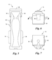
FIG. 4 is a right-side elevation view the mount of FIG. 1;
FIG. 5 is a back elevation view the mount of FIG. 1;
FIG. 6 is a top plan view the mount of FIG. 1;
FIG. 7 is bottom plan view of the mount of FIG. 1;
FIG. 8 is a partially exploded front isometric view of the mount of FIG. 1;
FIG. 9 is a front isometric view of the back-plate sub-assembly of the mount of FIG. 1;
FIG. 10 is a right side elevation view of the back-plate sub-assembly of the mount of FIG. 1;
FIG. 11 is a front isometrix view of the support-plate sub-assembly of the mount of FIG. 1;
FIG. 12 is a front elevation view of support-plate sub-assembly of the mount of FIG. 1;
FIG. 13 a left-side elevation view of the support-plate sub-assembly of the mount of FIG. 1;
FIG. 14 is a bottom plan view of the support-plate sub-assembly of the mount of FIG. 1;
FIG. 15 is a front elevation view of the movable latch-plate sub-assembly of the mount of FIG. 1;
FIG. 16 is a back elevation view of the movable latch-plate sub-assembly of the mount of FIG. 1;
FIG. 17 is a back isometric view of the movable latch-plate sub-assembly of the mount of FIG. 1;
FIG. 18 is bottom plan view of the movable latch-plate sub-assembly of the mount of FIG. 1;
FIG. 19 is a front elevation view of the housing sub-assembly of the mount of FIG. 1;
FIG. 20 is a back elevation view of the housing sub-assembly of the mount of FIG. 1;
FIG. 21 is a cross-sectional elevation view of the mount of FIG. 1 taken along the line B-B of FIG. 6;
FIG. 22 is a front isometric cross-sectional elevation view of the mount of FIG. 1 taken along the line A-A of FIG. 1;
FIG. 23 is a right side elevation view of the pawl of the mount of FIG. 1; and
FIG. 24 is front isometric view of the right-side intermediate mount of the mount of FIG. 1.
DETAILED DESCRIPTION OF THE INVENTION
Reference will now be made in detail to an embodiment of the invention, an example of which is illustrated in the accompanying drawings. The terminology used in the description of the invention herein is for the purpose of describing the preferred embodiment only and is not intended to be limiting of the invention.
As used in the description of the invention and the appended claims, the singular forms “a”, “an” and “the” are intended to include the plural forms as well, unless the context clearly indicates otherwise. The words “and/or” as used herein refers to and encompasses any and all possible combinations of one or more of the associated listed items. The words “comprises” and/or “comprising,” when used in this specification, specify the presence of stated features, integers, steps, operations, elements, and/or components, but do not preclude the presence or addition of one or more other features, integers, steps, operations, elements, components, and/or groups thereof.
The words “right,” “left,” “lower”, “upper”, ‘rearward” and “forward” designate directions in the drawings to which reference is made. The words “inwardly” and “outwardly” refer to directions toward and away from, respectively, the geometric center of the embodiment, and designated parts thereof. The terminology includes the words noted above, derivatives thereof and words of similar import.
Although the words first, second, etc., are used herein to describe various elements, these elements should not be limited by these words. These words are only used to distinguish one element from another. For example, a first length could be termed a second length, and, similarly, a second length could be termed a first length, without departing from the scope of the present invention.
The following description is directed towards various embodiments of the universal mount for a mobile hand-holdable electronic device in accordance with the present invention.
Referring to the drawings in detail, where like numerals indicate like elements throughout, there is shown in FIGS. 1-24 a first preferred embodiment of a universal mount for a mobile hand-holdable electronic device, generally designated 10, and hereinafter referred to as the “mount” 10 in accordance with the present invention. The mount 10 releaseably retains therein a mobile hand-holdable electronic device such as a tablet computer, cell phone, camera and the like.
Referring to the exploded front isometric view in FIG. 8, the mount 10 comprises a housing sub-assembly 12 within which a movable-plate sub-assembly 14 and a support-plate sub-assemble 16 to which the movable latch-plate sub-assembly 14 is slideably attached are disposed and enclosed therein by a back-plate sub-assembly 18 attached to the housing sub-assembly 12.
Referring to FIGS. 1-8, the housing sub-assembly 12 preferably has a generally rectangular housing base-plate 20 from which spaced-apart right (or first) and left (or second) housing side- plates 22, 24 having a length L1 extend upwardly to a housing top-plate 26. For mobile hand-holdable electronic devices, such as cell phones, L1 may be between four to eight inches, but could be larger than eight inches or smaller than four inches. For mobile hand-holdable electronic devices, such as pads or tablets, L1 may be between eight to twelve inches but could be greater than 12 inches or less than eight inches.
A housing front-plate 28 extending from the right housing side-plate 22 to the left housing side-plate 24 has a housing front-plate lower edge 28 a spaced from a housing base-plate front lip 30 and extends upwardly from the housing base-plate 20 a length L2 terminating in a housing front-plate upper edge 28 b. The remaining front portion of the housing sub-assembly 12 between the housing top-plate 26 and the housing front-plate upper edge 28 b provides and opening having a length L3 within which the position of the movable-plate sub-assembly 14 is adjusted to accommodate mobile hand-holdable electronic devices of various sizes. The multi-plate housing sub-assembly 12 is preferably injection molded as a single integrated piece. However, the multi-plate housing sub-assembly 12 may assembled from individually fabricated pieces joined together by well known material specific joining methods, such as adhesive bonding if the fabrication material is a polymeric material, conventional welding if the fabrication material is a metal of by any number of well known fasteners. Although the piece-parts comprising the housing sub-assembly 12 have been referred to as plates, in some instances, the plates need not be planar and could have a shell-like curvature.
The housing base-plate 20 is not limited to a rectangular shape and in some embodiments may have another geometric shape such as a square or any other polygon. In some embodiments the right and left housing base-plate side- walls 32, 34 may be extensions of the lower portion of the right and left housing side- plates 22, 24. In other embodiments, the lower portion of the right and left housing side-plates 22 may be contained within the right and left housing base-plate side- walls 32, 34.
A lower mount 36 configured to releaseably support and retain a portion of a lower edge of a mobile hand-holdable electronic device is fixedly attached to the front portion of the housing base-plate 20 between the housing base-plate front lip 30 and the housing front-plate lower edge 28 a. Preferably, the lower mount 36 has a V-shaped cross-section compatible with the lower edge of mobile hand-holdable electronic devices with a wide variety of configurations. In some embodiments, the lower mount 36 is not fixedly attached to the housing base-plate 20 and may be replaced by a base-plate tailored to the configuration of the lower edge of a particular mobile hand-holdable electronic device.
Referring to FIGS. 8 and 15-18, the movable latch-plate sub-assembly 14 includes a movable plate 38 slideably disposed within and attached to the housing sub-assembly 12 by latch pins 40 (see, FIG. 17) that extend outwardly from each side of the top portion of the movable plate 38 and engage slots 42 (see FIG. 8) in the opposed inner surfaces of the right and left housing side- plates 22, 24 adjacent the opening above the upper edge 28 b of the housing front-plate 28. A cantilevered brace 44 attached to the top of the movable plate 38 extends forward through the opening in the housing sub-assembly 12. The brace 44 has a generally rectangular shape extending the width of the movable plate 38 and has a V-shaped cross section for receiving and fixedly retaining an upper mount 46 having a configuration compatible with the upper edge of mobile hand-holdable electronic devices with a wide variety of configurations. In some embodiments, the upper mount 46 may not be fixedly attached to the brace 44 and may be replaceable with an upper mount tailored to the configuration of a particular mobile hand-holdable electronic device.
Referring to FIGS. 16-18, 21 and 22, a latch-plate sub-assembly rail 48 functioning as a rack is positioned along the right edge of the rearwardly facing surface of the latch-plate sub-assembly 14, extends rearwardly and has gear teeth 50 on an inwardly facing surface for engaging a gear wheel 52 (see, FIG. 21). A latch-plate sub-assembly bar 54 functioning as a ratchet bar is spaced from the left edge of the rearwardly facing surface of the latch-plate sub-assembly 14, extends rearwardly and has serrated teeth 56 on an outwardly facing surface for engaging a pawl 58 (See, FIGS. 21-23) permitting movement of the movable latch-plate sub-assembly 14 in one direction and preventing movement in the opposite direction.
A movable latch-plate sub-assembly channel 60 between the rail 48 and the bar 54 is centrally positioned on the rearwardly facing surface of the latch-plate sub-assembly 14. A rod 62 extending substantially the length of the latch-plate sub-assembly channel 60 terminates in an open end 62 a configured to receive one end of a movable latch-plate sub-assembly compression spring 64 (See, FIGS. 21 and 22) The other end of the latch-plate sub-assembly compression spring 64 is attached to and supported by the housing base plate 20.
Referring to FIGS. 8, 11-14, 21 and 22, the support-plate sub-assembly 16 is operatively coupled to the movable latch-plate sub-assembly 14 by (i) the support-plate sub-assembly gear wheel 52 rotatably mounted on a inwardly extending support-plate sub-assembly shaft 66 on the forwardly facing surface of the support-plate sub-assembly 16 and which engages the rail 48 on the rearwardly facing surface of the latch-plate sub-assembly 14, (ii) the support-plate sub-assembly pawl 58 which engages the ratchet bar 54 on the rearwardly facing surface of the latch-plate sub-assembly 14, and (iii) a support-plate sub-assembly channel 68 within which the latch-plate sub-assembly channel 60 is movable. The movable latch-plate sub-assembly 14 compression spring 64 upwardly biases the upper mount 46 away from the lower mount 36.
Referring to FIGS. 8 and 21-23, the pawl 58 comprises a pivoting catch 70 having an catch edge 72 at one end configured and positioned to engage the serrated teeth 56 of the ratchet bar 54 and a pawl release button 74 at the other end. Pawl pins 76 extending from opposite sides of the pivoting catch 70 are received and pivotably retained in sockets (not shown) in the inwardly facing surface of the housing front plate 28 and the opposed inwardly facing surface of the support-plate sub-assembly 16. A ratchet pawl compression spring (not shown) extends between a cradle 82 and the release button 74 biasing the pawl 58 in the ratchet bar 54 engaging position such that pressing of the release button 74 disengages the catch edge 72 from the serrated teeth 56 of the ratchet bar 54 allowing movable latch-plate sub-assembly compression spring 64 to expand, thereby moving the upper mount 44 upwardly and away from the lower mount 36. The pawl 58 may be locked in place by a slideable locking pin 80
Referring to FIGS. 1-4, 8 and 24, mount 10 may have an intermediate mount 84 positioned on the housing sub-assembly 12 between the lower mount 36 and the upper mount 44 to allow mobile hand-holdable electronic devices with small frames to be reliably received and releasably retained in the mount 10. The intermediate mount 84 comprises a pair of pivotable arms 86 stowed in recesses 88 in the right and left housing side plates 22, 24. Each pivotable arm 86 has a pivotable arm pin 90 with a collapsible tip allowing the pivotable arm pin 90 to be inserted in an arm hole 92 in the right and left recesses 88 such that upon insertion in the arm hole 92, the tip is first compressed and then expands providing a snap fit pivotably attaching them pivot arm 86 to the right or left side- plate 22, 24. In some embodiments, each pivotable arm 86 may be pivotably attached to the right and left side- plates 22, 24 by a threaded pivotable arm pin screwably inserted in each arm hole 92. The total range of travel of the pair of pivotable arms 86 is about 90 degrees. At zero degrees, the pivot arms 86 are stowed in the recesses 88 in the right and left housing side plates 22, 24 and held in the stowed position by the reverse angle feature of the pivotable arms 86 in conjunction with a similar reverse angle feature of the recesses 88. In some embodiments, a finger nail slot may be provided as a feature between the pivotable arms 86 and the housing right and left side plates and the housing front plate 28.
Referring to FIGS. 1 and 2, in some embodiments of the mount 10, the housing sub-assembly 12 may have a cold shoe mount 96 on one or more housing sub-assembly side and top plates 22, 24, 26 for mounting peripheral devices (e.g. external lights, microphones, and the like) which enhance the functionality of the mobile device.
As stated above for the housing sub-assembly 12, the several sub-assemblies described above are preferably fabricated by well known injection molding processes from compatible polymeric materials. However, the fabrication materials are not limited to polymerics. Other materials such as various metals or carbon fiber composites could be used.
A preferred method for assembling the mount 10 includes as a first step, placing the housing sub-assembly with the housing sub-assembly 12 front plate 28 facing downwardly on a flat surface. The movable-plate sub-assembly 14 is inserted into the front of the housing sub-assembly 12 such that the latch pins 38 extending outwardly from each side of the top portion of the movable plate 36 are slideably disposed in the slots 42 in the opposed inner surfaces of the right and left housing side-plated 22, 24 and the upper mount 46 extends past the housing front-plate 28 The movably latch-plate sub-assembly compression spring 64 is installed by sliding the spring 64 over the open end of the rod 62, making sure that both ends of the spring 64 are properly seated at their interface with the rod 62 and the housing base plate 20 and that the body of the spring 64 is located properly in the movable latch-plate sub-assembly channel 60. The gear wheel 52 is now installed on the inwardly extending shaft 66 of the forwardly facing surface of the support-plate sub-assembly 16. The ratcheting pawl 58 and compression spring (not shown) are installed on the inwardly extending shaft 66 of the forwardly facing surface of the support-plate sub-assembly 16 such that one end of the compression spring (not shown) is seated in the compression spring cradle 82 and the other end is seated in the pawl release button 74. Damping grease is applied to both the gear wheel 52 and the ratcheting pawl 58 to hold the components in place while installing the support-plate sub-assembly 16 is installed on the movable latch-plate sub-assembly 14 in the housing sub-assembly 12 making sure that the pivoting catch pivot pins 76 are inserted in the pivot pin sockets (not shown) in both the housing sub-assembly 12 and the support-plate sub-assembly 16. The support-plate sub-assembly 16 is now attached to the house sub-assembly 12 by threaded fasteners. In some embodiments, the support-plate sub-assembly 16 may be additionally attached to the house sub-assembly 12 by dovetail joints, adhesive bonds or other well known joining methods.
Referring to FIGS. 8-10, the housing back-plate sub-assembly 18 has a generally rectangular shell like shape with inwardly extending flat head studs 98 positioned at each corner of the housing back-plate sub-assembly 18 for insertion in keyholes 100 in the support-plate sub-assembly 16 in register with the flat head studs 98 which upon insertion in the keyholes 100 and the upward sliding of the housing back-plate sub-assembly 18 relative to the support-plate sub-assembly 16 locks the two sub-assemblies 16, 18 together, enclosing the house sub-assembly 12.
It will be appreciated by those skilled in the art that changes could be made to the embodiment described above without departing from the presently-disclosed invention. It is understood, therefore, that this invention is not limited to the particular embodiment disclosed, but it is intended to cover modifications within the spirit and scope of the present invention as defined by the appended claim.

Claims (8)

I claim:
1. A universal mount able to accommodate mobile hand-holdable electronic devices of various sizes having a device lower edge spaced from a device upper edge, the universal mount comprising:
a housing sub-assembly having a housing sub-assembly base-plate with a lower mount attached thereto, the lower mount configured to releaseably receive the device lower edge;
a movable latch-plate sub-assembly disposed in and slideably attached to the housing sub-assembly, the movable latch-plate sub-assembly having an upper mount attached thereto, the upper mount aligned with the lower mount at a position above the lower mount and configured to releaseably receive the device upper edge, the position of the upper mount being adjustable relative to the lower mount to accommodate mobile hand-holdable electronic devices of various sizes;
a support-plate sub-assembly fixedly disposed in the housing sub-assembly, the movable latch-plate sub-assembly slideably attached to the support-plate sub-assembly; and
a back-plate sub-assembly attached to the housing sub-assembly and enclosing the movable latch-plate sub-assembly and the support-plate sub-assembly in the housing sub-assembly,
wherein the housing sub-assembly further comprises:
a first housing sub-assembly side plate and a second housing sub-assembly side plate spaced from the first housing sub-assembly side plate, the first and second housing sub-assembly side plates having a length L1 and extending upwardly from the housing base-plate to a housing top-plate extending from the first housing sub-assembly side plate to the second housing sub-assembly side plate;
a housing sub-assembly front-plate extending from the first housing sub-assembly side plate to the second housing sub-assembly side plate and upwardly from the housing sub-assembly base-plate a length L2 less than the length L1; and
a housing sub-assembly opening in the housing sub-assembly between the housing sub-assembly top-plate and the housing sub-assembly front-plate having a length L3 within which the position of the movable-plate sub-assembly is adjustable.
2. The universal mount according to claim 1, wherein the housing sub-assembly is injection molded as a single integrated piece.
3. The universal mount according to claim 1, wherein the housing sub-assembly further comprises a cold shoe on at least one of the first housing sub-assembly side plate, the a second housing sub-assembly side plate and the housing sub-assembly top plate, the cold shoe configured to mount a peripheral device.
4. A universal mount able to accommodate mobile hand-holdable electronic devices of various sizes having a device lower edge spaced from a device upper edge, the universal mount comprising:
a housing sub-assembly having a housing sub-assembly base-plate with a lower mount attached thereto, the lower mount configured to releaseably receive the device lower edge;
a movable latch-plate sub-assembly disposed in and slideably attached to the housing sub-assembly, the movable latch-plate sub-assembly having an upper mount attached thereto, the upper mount aligned with the lower mount at a position above the lower mount and configured to releaseably receive the device upper edge, the position of the upper mount being adjustable relative to the lower mount to accommodate mobile hand-holdable electronic devices of various sizes;
a support-plate sub-assembly fixedly disposed in the housing sub-assembly, the moveable latch-plate sub-assembly slideably attached to the support-plate sub-assembly; and
a back-plate sub-assembly attached to the housing sub-assembly and enclosing the moveable latch-plate sub-assembly and the support-plate sub-assembly in the housing sub-assembly,
wherein the movable latch-plate sub-assembly further comprises:
a moveable latch-plate sub-assembly rail positioned along a right edge of a rearwardly facing surface of the movable latch-plate sub-assembly, the movable latch-plate sub-assembly rail extending rearwardly and configured as a rack having gear teeth on an inwardly facing rack surface; and
wherein the support-plate sub-assembly comprises:
a forwardly facing support-plate sub-assembly surface;
a support-plate shaft extending inwardly from the forwardly facing support-plate sub-assembly surface, and
a support-plate sub-assembly gear wheel rotatably mounted on the support-plate sub-assembly shaft and engaging the gear teeth of the rack on the rearwardly facing surface of the movable latch-plate sub-assembly.
5. A universal mount able to accommodate mobile hand-holdable electronic devices of various sizes having a device lower edge spaced from a device upper edge, the universal mount comprising:
a housing sub-assembly having a housing sub-assembly base-plate with a lower mount attached thereto, the lower mount configured to releaseably receive the device lower edge;
a movable latch-plate sub-assembly disposed in and slideably attached to the housing sub-assembly, the movable latch-plate sub-assembly having an upper mount attached thereto, the upper mount aligned with the lower mount at a position above the lower mount and configured to releaseably receive the device upper edge, the position of the upper mount being adjustable relative to the lower mount to accommodate mobile hand-holdable electronic devices of various sizes;
a support-plate sub-assembly fixedly disposed in the housing sub-assembly, the movable latch-plate sub-assembly slideably attached to the support-plate sub-assembly; and
a back-plate sub-assembly attached to the housing sub-assembly and enclosing the movable latch-plate sub-assembly and the support-plate sub-assembly in the housing sub-assembly;
wherein the movable latch-plate sub-assembly comprises:
a movable latch-plate sub-assembly bar spaced from the left edge of a rearwardly facing surface of the movable latch-plate sub-assembly, the movable latch-plate sub-assembly bar extending rearwardly and configured as a ratchet bar with serrated teeth on an outwardly facing ratchet bar surface, and
wherein the support-plate sub-assembly comprises:
a support-plate sub-assembly pawl which engages the serrated teeth of the ratchet bar on the rearwardly facing surface of the latch-plate sub-assembly permitting movement of the movable latch-plate sub-assembly in one direction and preventing movement of the movable latch-plate sub-assembly in the opposite direction.
6. The universal mount according to claim 5, wherein the pawl comprises:
a pivoting catch having an catch edge at a first pawl end configured and positioned to engage the serrated teeth of the ratchet bar and a pawl release button at a second pawl end.
7. A universal mount able to accommodate mobile hand-holdable electronic devices of various sizes having a device lower edge spaced from a device upper edge, the universal mount comprising:
a housing sub-assembly having a housing sub-assembly base-plate with a lower mount attached thereto, the lower mount configured to releaseably receive the device lower edge;
a movable latch-plate sub-assembly disposed in and slideably attached to the housing sub-assembly, the moveable latch plate sub-assembly having an upper mount attached thereto, the upper mount aligned with the lower mount at a position above the lower mount and configured to releaseably receive the device upper edge, the position of the upper mount being adjustable relative to the lower mount to accommodate mobile hand-holdable electronic devices of various sizes;
a support-plate sub-assembly fixedly disposed in the housing sub-assembly, the movable latch-plate sub-assembly attached to the support-plate sub-assembly; and
a back-plate sub-assembly attached to the housing sub-assembly and enclosing the movable latch-plate sub-assembly and the support-plate sub-assembly in the housing sub-assembly;
wherein the movable latch-plate sub-assembly comprises:
a rearwardly facing movable latch-plate sub-assembly surface having a centrally-positioned downwardly-extending movable latch-plate sub-assembly first slot spaced apart from a centrally-positioned downwardly-extending movable latch-plate sub-assembly second slot; and
a movable latch-plate sub-assembly rod disposed between the movable latch-plate sub-assembly first and second spaced-apart slots, the movable latch-plate sub-assembly rod extending downwardly substantially a movable latch-plate slot length and terminating in a movable latch-plate sub-assembly rod compression spring mount, and
wherein the support-plate sub-assembly comprises:
a generally U-shaped support-plate sub-assembly channel having spaced-apart first and second channel arms slideably disposed in the movable latch-plate sub-assembly first and second spaced-apart slots;
a movable latch-plate sub-assembly compression spring disposed in the support-plate sub-assembly channel having a first compression spring end coupled to the movable latch-plate sub-assembly rod compression spring mount and a second compression spring end attached to and supported by the housing base plate, the movable latch-plate sub-assembly compression spring upwardly biasing the upper mount away from the lower mount.
8. A universal mount able to accommodate mobile hand-holdable electronic devices of various sizes having a device lower edge spaced from a device upper , the universal mount comprising:
a housing sub-assembly having a housing sub-assembly base-plate with a lower mount attached thereto, the lower mount configured to releaseably receive the device lower edge;
a movable latch-plate sub-assembly disposed in and slideably attached to the housing sub-assembly, the movable latch-plate sub-assembly having an upper mount attached thereto, the upper mount aligned with the lower mount at a position above the lower mount and configured to releaseably receive the device upper edge, the position of the upper mount being adjustable relative to the lower mount to accommodate mobile hand-holdable electronic devices of various sizes;
a support-plate sub-assembly fixedly disposed in the housing sub-assemnly, the movable latch-plate sub-assembly slideably attached to the support-plate sub-assembly; and
a back-plate sub-assembly attached to the housing sub-assembly and enclosing the movable latch-plate sub-assembly and the support-plate sub-assembly in the housing sub-assembly;
wherein the housing sub-assembly further comprises:
a first recess in the first housing sub-assembly side plate;
a second recess in the second housing sub-assembly side plate;
an intermediate mount positioned between the lower mount and the upper mount, the intermediate mount comprising:
a first extendable arm stowed in the first recess and pivotably attached to the first housing sub-assembly side plate; and
a second extendable arm stowed in the second recess and pivotably attached to the second housing sub-assembly side plate,
the first and second extendable anus are configured to releaseably receive the device lower edge when the first and second extendable arms are in an extended position.
US15/807,971 2016-11-10 2017-11-09 Universal mount for a mobile hand-holdable electronic device Active US10172246B2 (en)

Priority Applications (1)

Application Number Priority Date Filing Date Title
US15/807,971 US10172246B2 (en) 2016-11-10 2017-11-09 Universal mount for a mobile hand-holdable electronic device

Applications Claiming Priority (2)

Application Number Priority Date Filing Date Title
US201662420171P 2016-11-10 2016-11-10
US15/807,971 US10172246B2 (en) 2016-11-10 2017-11-09 Universal mount for a mobile hand-holdable electronic device

Publications (2)

Publication Number Publication Date
US20180132364A1 US20180132364A1 (en) 2018-05-10
US10172246B2 true US10172246B2 (en) 2019-01-01

Family

ID=60413303

Family Applications (1)

Application Number Title Priority Date Filing Date
US15/807,971 Active US10172246B2 (en) 2016-11-10 2017-11-09 Universal mount for a mobile hand-holdable electronic device

Country Status (2)

Country Link
US (1) US10172246B2 (en)
WO (1) WO2018089620A1 (en)

Cited By (7)

* Cited by examiner, † Cited by third party
Publication number Priority date Publication date Assignee Title
US20180274715A1 (en) * 2015-10-29 2018-09-27 Alberto Rene Somoano Adjustable Portable Electronic Device Holder
US20190384359A1 (en) * 2018-06-19 2019-12-19 Robert Bosch Gmbh Holding Device for a Handheld Computer Unit for Controlling a Machine
US11277506B2 (en) 2020-05-26 2022-03-15 National Products, Inc. Cradles for mobile devices with one or more biasing tabs and methods of making and using
US11489350B2 (en) * 2019-12-23 2022-11-01 National Products, Inc. Cradle for mobile devices with resilient guides and methods of making and using
US11510326B2 (en) * 2020-05-21 2022-11-22 Utto Inc. Mobile device retainer for field mapping and data collection
US11652326B2 (en) 2021-04-30 2023-05-16 National Products, Inc. Dock with flexible locator pins and methods of making and using
US20230263280A1 (en) * 2022-02-22 2023-08-24 Chien-Ting Lin Tablet holder

Families Citing this family (6)

* Cited by examiner, † Cited by third party
Publication number Priority date Publication date Assignee Title
USD901507S1 (en) 2018-09-05 2020-11-10 ACCO Brands Corporation Electronic dock
US10788857B2 (en) 2018-09-05 2020-09-29 ACCO Brands Corporation Dock for a portable electronic device
US20200178408A1 (en) * 2018-12-03 2020-06-04 Nanning Fugui Precision Industrial Co., Ltd. Mounting mechanism and electronic device having the same
CN111698869A (en) * 2019-03-14 2020-09-22 南宁富桂精密工业有限公司 Drawing type device
CN110730577B (en) * 2019-09-20 2021-08-31 广东恒梓煜科技有限公司 Distribution network automation control box convenient to overhaul
CN112118692B (en) * 2020-09-08 2022-03-18 广西智电电力工程有限公司 Safety protection equipment for power facility used in power construction site

Citations (18)

* Cited by examiner, † Cited by third party
Publication number Priority date Publication date Assignee Title
US5903645A (en) * 1996-10-23 1999-05-11 Tsay; Wen-Feng Clamping device for mobile phones
US6229893B1 (en) 1998-11-27 2001-05-08 E. Lead Electronic Co., Ltd. Universal hands-free receiver for a mobile telephone
US20040184223A1 (en) 2003-03-21 2004-09-23 Yeh Ta Kuang Attachment assembly for personal digital assistant
US7551458B2 (en) * 2005-05-24 2009-06-23 Carnevali Jeffrey D Secure universal mounting apparatus
EP2218611A1 (en) 2009-02-13 2010-08-18 Funkwerk Dabendorf GmbH Holder for a mobile electronic device for temporarily fixing the device to the holder
US8640868B2 (en) 2012-01-13 2014-02-04 John O'Dowd Case assembly and method for covering and protecting a portable device
US9103487B2 (en) * 2012-03-24 2015-08-11 Daymen Us, Inc. Adjustable mounting clip and system using same
US9108096B2 (en) * 2013-08-30 2015-08-18 Karsten Manufacturing Corporation Portable electronic device holders and methods to manufacture portable electronic device holders
US20150359114A1 (en) * 2014-06-06 2015-12-10 Yongjian Yang Portable clamping apparatus for mobile equipment
US20160108942A1 (en) * 2014-10-16 2016-04-21 Tsung-Yao Yu Support Rack
US9386194B2 (en) 2013-02-25 2016-07-05 iOgrapher, LLC Receptacle for an image capture computing device
US9581180B2 (en) * 2014-05-15 2017-02-28 Ability Enterprise Co., Ltd. Clamper and device using the same
US9586530B2 (en) * 2015-05-08 2017-03-07 Sehhan KIM Holder for holding portable device
US9695977B2 (en) * 2015-05-30 2017-07-04 Gript Inc. Electronic device holder with tripod mount and hand grip
USD794606S1 (en) 2016-05-31 2017-08-15 Sz Dji Osmo Technology Co., Ltd. Gimbal with handle
US9776577B2 (en) * 2012-08-13 2017-10-03 Jeffrey D. Carnevali Modular electronics platform
US9840264B1 (en) * 2015-05-12 2017-12-12 Chad R. Johnson Portable electronic device holder for a shopping cart
US9924005B1 (en) * 2017-01-26 2018-03-20 Cam Caddie Universal phone mounting apparatus

Patent Citations (19)

* Cited by examiner, † Cited by third party
Publication number Priority date Publication date Assignee Title
US5903645A (en) * 1996-10-23 1999-05-11 Tsay; Wen-Feng Clamping device for mobile phones
US6229893B1 (en) 1998-11-27 2001-05-08 E. Lead Electronic Co., Ltd. Universal hands-free receiver for a mobile telephone
US20040184223A1 (en) 2003-03-21 2004-09-23 Yeh Ta Kuang Attachment assembly for personal digital assistant
US6959899B2 (en) * 2003-03-21 2005-11-01 Ta Kuang Yeh Attachment assembly for personal digital assistant
US7551458B2 (en) * 2005-05-24 2009-06-23 Carnevali Jeffrey D Secure universal mounting apparatus
EP2218611A1 (en) 2009-02-13 2010-08-18 Funkwerk Dabendorf GmbH Holder for a mobile electronic device for temporarily fixing the device to the holder
US8640868B2 (en) 2012-01-13 2014-02-04 John O'Dowd Case assembly and method for covering and protecting a portable device
US9103487B2 (en) * 2012-03-24 2015-08-11 Daymen Us, Inc. Adjustable mounting clip and system using same
US9776577B2 (en) * 2012-08-13 2017-10-03 Jeffrey D. Carnevali Modular electronics platform
US9386194B2 (en) 2013-02-25 2016-07-05 iOgrapher, LLC Receptacle for an image capture computing device
US9108096B2 (en) * 2013-08-30 2015-08-18 Karsten Manufacturing Corporation Portable electronic device holders and methods to manufacture portable electronic device holders
US9581180B2 (en) * 2014-05-15 2017-02-28 Ability Enterprise Co., Ltd. Clamper and device using the same
US20150359114A1 (en) * 2014-06-06 2015-12-10 Yongjian Yang Portable clamping apparatus for mobile equipment
US20160108942A1 (en) * 2014-10-16 2016-04-21 Tsung-Yao Yu Support Rack
US9586530B2 (en) * 2015-05-08 2017-03-07 Sehhan KIM Holder for holding portable device
US9840264B1 (en) * 2015-05-12 2017-12-12 Chad R. Johnson Portable electronic device holder for a shopping cart
US9695977B2 (en) * 2015-05-30 2017-07-04 Gript Inc. Electronic device holder with tripod mount and hand grip
USD794606S1 (en) 2016-05-31 2017-08-15 Sz Dji Osmo Technology Co., Ltd. Gimbal with handle
US9924005B1 (en) * 2017-01-26 2018-03-20 Cam Caddie Universal phone mounting apparatus

Non-Patent Citations (1)

* Cited by examiner, † Cited by third party
Title
Int'l Search Report and Written Opinion dated Feb. 6, 2018 in Int'l Application No. PCT/US2017/060837.

Cited By (9)

* Cited by examiner, † Cited by third party
Publication number Priority date Publication date Assignee Title
US20180274715A1 (en) * 2015-10-29 2018-09-27 Alberto Rene Somoano Adjustable Portable Electronic Device Holder
US10774978B2 (en) * 2015-10-29 2020-09-15 Alberto Rene Somoano Adjustable portable electronic device holder
US20190384359A1 (en) * 2018-06-19 2019-12-19 Robert Bosch Gmbh Holding Device for a Handheld Computer Unit for Controlling a Machine
US10890943B2 (en) * 2018-06-19 2021-01-12 Robert Bosch Gmbh Holding device for a handheld computer unit for controlling a machine
US11489350B2 (en) * 2019-12-23 2022-11-01 National Products, Inc. Cradle for mobile devices with resilient guides and methods of making and using
US11510326B2 (en) * 2020-05-21 2022-11-22 Utto Inc. Mobile device retainer for field mapping and data collection
US11277506B2 (en) 2020-05-26 2022-03-15 National Products, Inc. Cradles for mobile devices with one or more biasing tabs and methods of making and using
US11652326B2 (en) 2021-04-30 2023-05-16 National Products, Inc. Dock with flexible locator pins and methods of making and using
US20230263280A1 (en) * 2022-02-22 2023-08-24 Chien-Ting Lin Tablet holder

Also Published As

Publication number Publication date
WO2018089620A1 (en) 2018-05-17
US20180132364A1 (en) 2018-05-10

Similar Documents

Publication Publication Date Title
US10172246B2 (en) Universal mount for a mobile hand-holdable electronic device
US10416538B2 (en) Quick-release ball-and-socket joint camera mount
US9402016B1 (en) Electronic device mount
US8388243B1 (en) Apparatus for holding a portable media device
US8857775B1 (en) Camera mount with spring clamp
US8262299B2 (en) Panoramic camera mount
US20160116828A1 (en) Quick-release ball-and-socket joint camera mount
US20110064401A1 (en) Coupling and accessory system for electronic devices
US9454065B2 (en) Device support and trigger apparatus
US20160077411A1 (en) Frame and insert for mounting a mobile device to a tripod
US20150370150A1 (en) Auxiliary optical components for mobile devices
JP5850050B2 (en) Camera mounting apparatus and camera mounting method
US11240359B2 (en) Auxiliary grip system
US7963494B2 (en) Holder, and assembly of the holder and an electronic device
US20060231667A1 (en) Electronic apparatus with detachable support
US7870962B2 (en) Multi-functional storage apparatus
JPS58501730A (en) Portable equipment for carrying cameras, etc. in a ready-to-use state
USD508065S1 (en) Digital camera
KR101713471B1 (en) Receptacle for an image capture computing device
KR20060097355A (en) Clip type cradle apparatus for mobile terminal can attached and removed on camera tripod
JP2010039430A (en) Attachment for accessory and imaging apparatus
JP2003255453A (en) Camera
US6793413B1 (en) Nose pad for camera
KR101583943B1 (en) Case for portable electric device
KR20190087682A (en) Selkabon

Legal Events

Date Code Title Description
FEPP Fee payment procedure

Free format text: ENTITY STATUS SET TO UNDISCOUNTED (ORIGINAL EVENT CODE: BIG.); ENTITY STATUS OF PATENT OWNER: SMALL ENTITY

FEPP Fee payment procedure

Free format text: ENTITY STATUS SET TO SMALL (ORIGINAL EVENT CODE: SMAL); ENTITY STATUS OF PATENT OWNER: SMALL ENTITY

AS Assignment

Owner name: PADCASTER LLC, NEW YORK

Free format text: ASSIGNMENT OF ASSIGNORS INTEREST;ASSIGNOR:APTER, JOSH;REEL/FRAME:044697/0748

Effective date: 20180111

STCF Information on status: patent grant

Free format text: PATENTED CASE

MAFP Maintenance fee payment

Free format text: PAYMENT OF MAINTENANCE FEE, 4TH YR, SMALL ENTITY (ORIGINAL EVENT CODE: M2551); ENTITY STATUS OF PATENT OWNER: SMALL ENTITY

Year of fee payment: 4