US10170783B2 - Manufacture of a fuel cell with liquid electrolyte migration prevention - Google Patents
Manufacture of a fuel cell with liquid electrolyte migration prevention Download PDFInfo
- Publication number
- US10170783B2 US10170783B2 US13/145,626 US200913145626A US10170783B2 US 10170783 B2 US10170783 B2 US 10170783B2 US 200913145626 A US200913145626 A US 200913145626A US 10170783 B2 US10170783 B2 US 10170783B2
- Authority
- US
- United States
- Prior art keywords
- barrier
- separator plate
- plate assembly
- edge
- land region
- Prior art date
- Legal status (The legal status is an assumption and is not a legal conclusion. Google has not performed a legal analysis and makes no representation as to the accuracy of the status listed.)
- Active, expires
Links
- 239000000446 fuel Substances 0.000 title claims abstract description 62
- 238000013508 migration Methods 0.000 title claims abstract description 19
- 230000005012 migration Effects 0.000 title claims abstract description 19
- 239000011244 liquid electrolyte Substances 0.000 title claims abstract description 11
- 238000004519 manufacturing process Methods 0.000 title claims description 11
- 230000002265 prevention Effects 0.000 title 1
- 230000004888 barrier function Effects 0.000 claims abstract description 54
- 230000002209 hydrophobic effect Effects 0.000 claims abstract description 12
- 229920001973 fluoroelastomer Polymers 0.000 claims abstract description 8
- 239000004820 Pressure-sensitive adhesive Substances 0.000 claims abstract description 7
- 238000000034 method Methods 0.000 claims description 24
- 239000000463 material Substances 0.000 claims description 8
- 229920001343 polytetrafluoroethylene Polymers 0.000 claims description 8
- 239000004812 Fluorinated ethylene propylene Substances 0.000 claims description 3
- 229920009441 perflouroethylene propylene Polymers 0.000 claims description 3
- YCKRFDGAMUMZLT-UHFFFAOYSA-N Fluorine atom Chemical compound [F] YCKRFDGAMUMZLT-UHFFFAOYSA-N 0.000 claims description 2
- 239000003522 acrylic cement Substances 0.000 claims description 2
- HQQADJVZYDDRJT-UHFFFAOYSA-N ethene;prop-1-ene Chemical group C=C.CC=C HQQADJVZYDDRJT-UHFFFAOYSA-N 0.000 claims description 2
- 229910052731 fluorine Inorganic materials 0.000 claims description 2
- 239000011737 fluorine Substances 0.000 claims description 2
- 238000011065 in-situ storage Methods 0.000 claims description 2
- 239000013464 silicone adhesive Substances 0.000 claims description 2
- 229920001600 hydrophobic polymer Polymers 0.000 claims 6
- 229920006026 co-polymeric resin Polymers 0.000 claims 1
- 238000010438 heat treatment Methods 0.000 claims 1
- 229920006254 polymer film Polymers 0.000 claims 1
- NBIIXXVUZAFLBC-UHFFFAOYSA-N Phosphoric acid Chemical compound OP(O)(O)=O NBIIXXVUZAFLBC-UHFFFAOYSA-N 0.000 abstract description 18
- 229910000147 aluminium phosphate Inorganic materials 0.000 abstract description 8
- 239000007767 bonding agent Substances 0.000 abstract description 5
- 210000004027 cell Anatomy 0.000 description 92
- 239000002253 acid Substances 0.000 description 41
- 239000000376 reactant Substances 0.000 description 16
- 239000003792 electrolyte Substances 0.000 description 11
- 239000003570 air Substances 0.000 description 9
- 239000001257 hydrogen Substances 0.000 description 8
- 229910052739 hydrogen Inorganic materials 0.000 description 8
- 230000032683 aging Effects 0.000 description 7
- 239000004810 polytetrafluoroethylene Substances 0.000 description 7
- 238000012546 transfer Methods 0.000 description 7
- IJGRMHOSHXDMSA-UHFFFAOYSA-N Atomic nitrogen Chemical compound N#N IJGRMHOSHXDMSA-UHFFFAOYSA-N 0.000 description 6
- UFHFLCQGNIYNRP-UHFFFAOYSA-N Hydrogen Chemical compound [H][H] UFHFLCQGNIYNRP-UHFFFAOYSA-N 0.000 description 6
- 238000005086 pumping Methods 0.000 description 6
- 229920001971 elastomer Polymers 0.000 description 5
- 239000000806 elastomer Substances 0.000 description 5
- 230000006835 compression Effects 0.000 description 4
- 238000007906 compression Methods 0.000 description 4
- 239000011159 matrix material Substances 0.000 description 4
- 230000003647 oxidation Effects 0.000 description 4
- 238000007254 oxidation reaction Methods 0.000 description 4
- NIXOWILDQLNWCW-UHFFFAOYSA-N acrylic acid group Chemical group C(C=C)(=O)O NIXOWILDQLNWCW-UHFFFAOYSA-N 0.000 description 3
- 230000000712 assembly Effects 0.000 description 3
- 238000000429 assembly Methods 0.000 description 3
- 238000005260 corrosion Methods 0.000 description 3
- 230000007797 corrosion Effects 0.000 description 3
- 238000013461 design Methods 0.000 description 3
- -1 hydrogen ions Chemical class 0.000 description 3
- 229910052757 nitrogen Inorganic materials 0.000 description 3
- 239000007800 oxidant agent Substances 0.000 description 3
- 230000001590 oxidative effect Effects 0.000 description 3
- 238000012360 testing method Methods 0.000 description 3
- OKTJSMMVPCPJKN-UHFFFAOYSA-N Carbon Chemical compound [C] OKTJSMMVPCPJKN-UHFFFAOYSA-N 0.000 description 2
- MCMNRKCIXSYSNV-UHFFFAOYSA-N Zirconium dioxide Chemical compound O=[Zr]=O MCMNRKCIXSYSNV-UHFFFAOYSA-N 0.000 description 2
- 230000001133 acceleration Effects 0.000 description 2
- QVGXLLKOCUKJST-UHFFFAOYSA-N atomic oxygen Chemical compound [O] QVGXLLKOCUKJST-UHFFFAOYSA-N 0.000 description 2
- 229910052799 carbon Inorganic materials 0.000 description 2
- 239000003575 carbonaceous material Substances 0.000 description 2
- 210000003850 cellular structure Anatomy 0.000 description 2
- 238000006243 chemical reaction Methods 0.000 description 2
- 238000011156 evaluation Methods 0.000 description 2
- 239000012530 fluid Substances 0.000 description 2
- PCHJSUWPFVWCPO-UHFFFAOYSA-N gold Chemical compound [Au] PCHJSUWPFVWCPO-UHFFFAOYSA-N 0.000 description 2
- 239000007788 liquid Substances 0.000 description 2
- 239000001301 oxygen Substances 0.000 description 2
- 229910052760 oxygen Inorganic materials 0.000 description 2
- 238000007789 sealing Methods 0.000 description 2
- XLYOFNOQVPJJNP-UHFFFAOYSA-N water Chemical compound O XLYOFNOQVPJJNP-UHFFFAOYSA-N 0.000 description 2
- 229920002449 FKM Polymers 0.000 description 1
- 229920006362 Teflon® Polymers 0.000 description 1
- 238000010521 absorption reaction Methods 0.000 description 1
- 150000001450 anions Chemical class 0.000 description 1
- 238000001816 cooling Methods 0.000 description 1
- 229920001577 copolymer Polymers 0.000 description 1
- 230000001627 detrimental effect Effects 0.000 description 1
- 238000011161 development Methods 0.000 description 1
- 230000018109 developmental process Effects 0.000 description 1
- 230000008020 evaporation Effects 0.000 description 1
- 238000001704 evaporation Methods 0.000 description 1
- 238000001125 extrusion Methods 0.000 description 1
- 239000004744 fabric Substances 0.000 description 1
- 239000007789 gas Substances 0.000 description 1
- 150000002431 hydrogen Chemical class 0.000 description 1
- KJLLKLRVCJAFRY-UHFFFAOYSA-N mebutizide Chemical compound ClC1=C(S(N)(=O)=O)C=C2S(=O)(=O)NC(C(C)C(C)CC)NC2=C1 KJLLKLRVCJAFRY-UHFFFAOYSA-N 0.000 description 1
- 238000002844 melting Methods 0.000 description 1
- 230000008018 melting Effects 0.000 description 1
- 238000009428 plumbing Methods 0.000 description 1
- 239000002952 polymeric resin Substances 0.000 description 1
- 238000003860 storage Methods 0.000 description 1
- 239000000758 substrate Substances 0.000 description 1
- 229920003249 vinylidene fluoride hexafluoropropylene elastomer Polymers 0.000 description 1
Images


Classifications
-
- H—ELECTRICITY
- H01—ELECTRIC ELEMENTS
- H01M—PROCESSES OR MEANS, e.g. BATTERIES, FOR THE DIRECT CONVERSION OF CHEMICAL ENERGY INTO ELECTRICAL ENERGY
- H01M8/00—Fuel cells; Manufacture thereof
- H01M8/24—Grouping of fuel cells, e.g. stacking of fuel cells
- H01M8/241—Grouping of fuel cells, e.g. stacking of fuel cells with solid or matrix-supported electrolytes
- H01M8/242—Grouping of fuel cells, e.g. stacking of fuel cells with solid or matrix-supported electrolytes comprising framed electrodes or intermediary frame-like gaskets
-
- H—ELECTRICITY
- H01—ELECTRIC ELEMENTS
- H01M—PROCESSES OR MEANS, e.g. BATTERIES, FOR THE DIRECT CONVERSION OF CHEMICAL ENERGY INTO ELECTRICAL ENERGY
- H01M8/00—Fuel cells; Manufacture thereof
- H01M8/08—Fuel cells with aqueous electrolytes
- H01M8/086—Phosphoric acid fuel cells [PAFC]
-
- H—ELECTRICITY
- H01—ELECTRIC ELEMENTS
- H01M—PROCESSES OR MEANS, e.g. BATTERIES, FOR THE DIRECT CONVERSION OF CHEMICAL ENERGY INTO ELECTRICAL ENERGY
- H01M8/00—Fuel cells; Manufacture thereof
- H01M8/02—Details
-
- H—ELECTRICITY
- H01—ELECTRIC ELEMENTS
- H01M—PROCESSES OR MEANS, e.g. BATTERIES, FOR THE DIRECT CONVERSION OF CHEMICAL ENERGY INTO ELECTRICAL ENERGY
- H01M8/00—Fuel cells; Manufacture thereof
- H01M8/02—Details
- H01M8/0271—Sealing or supporting means around electrodes, matrices or membranes
- H01M8/028—Sealing means characterised by their material
- H01M8/0284—Organic resins; Organic polymers
-
- H—ELECTRICITY
- H01—ELECTRIC ELEMENTS
- H01M—PROCESSES OR MEANS, e.g. BATTERIES, FOR THE DIRECT CONVERSION OF CHEMICAL ENERGY INTO ELECTRICAL ENERGY
- H01M8/00—Fuel cells; Manufacture thereof
- H01M8/02—Details
- H01M8/0271—Sealing or supporting means around electrodes, matrices or membranes
- H01M8/0286—Processes for forming seals
-
- H—ELECTRICITY
- H01—ELECTRIC ELEMENTS
- H01M—PROCESSES OR MEANS, e.g. BATTERIES, FOR THE DIRECT CONVERSION OF CHEMICAL ENERGY INTO ELECTRICAL ENERGY
- H01M8/00—Fuel cells; Manufacture thereof
- H01M8/04—Auxiliary arrangements, e.g. for control of pressure or for circulation of fluids
-
- H—ELECTRICITY
- H01—ELECTRIC ELEMENTS
- H01M—PROCESSES OR MEANS, e.g. BATTERIES, FOR THE DIRECT CONVERSION OF CHEMICAL ENERGY INTO ELECTRICAL ENERGY
- H01M8/00—Fuel cells; Manufacture thereof
- H01M8/24—Grouping of fuel cells, e.g. stacking of fuel cells
-
- H—ELECTRICITY
- H01—ELECTRIC ELEMENTS
- H01M—PROCESSES OR MEANS, e.g. BATTERIES, FOR THE DIRECT CONVERSION OF CHEMICAL ENERGY INTO ELECTRICAL ENERGY
- H01M8/00—Fuel cells; Manufacture thereof
- H01M8/02—Details
- H01M8/0202—Collectors; Separators, e.g. bipolar separators; Interconnectors
- H01M8/0204—Non-porous and characterised by the material
- H01M8/0223—Composites
- H01M8/0228—Composites in the form of layered or coated products
-
- Y—GENERAL TAGGING OF NEW TECHNOLOGICAL DEVELOPMENTS; GENERAL TAGGING OF CROSS-SECTIONAL TECHNOLOGIES SPANNING OVER SEVERAL SECTIONS OF THE IPC; TECHNICAL SUBJECTS COVERED BY FORMER USPC CROSS-REFERENCE ART COLLECTIONS [XRACs] AND DIGESTS
- Y02—TECHNOLOGIES OR APPLICATIONS FOR MITIGATION OR ADAPTATION AGAINST CLIMATE CHANGE
- Y02E—REDUCTION OF GREENHOUSE GAS [GHG] EMISSIONS, RELATED TO ENERGY GENERATION, TRANSMISSION OR DISTRIBUTION
- Y02E60/00—Enabling technologies; Technologies with a potential or indirect contribution to GHG emissions mitigation
- Y02E60/30—Hydrogen technology
- Y02E60/50—Fuel cells
-
- Y—GENERAL TAGGING OF NEW TECHNOLOGICAL DEVELOPMENTS; GENERAL TAGGING OF CROSS-SECTIONAL TECHNOLOGIES SPANNING OVER SEVERAL SECTIONS OF THE IPC; TECHNICAL SUBJECTS COVERED BY FORMER USPC CROSS-REFERENCE ART COLLECTIONS [XRACs] AND DIGESTS
- Y02—TECHNOLOGIES OR APPLICATIONS FOR MITIGATION OR ADAPTATION AGAINST CLIMATE CHANGE
- Y02P—CLIMATE CHANGE MITIGATION TECHNOLOGIES IN THE PRODUCTION OR PROCESSING OF GOODS
- Y02P70/00—Climate change mitigation technologies in the production process for final industrial or consumer products
- Y02P70/50—Manufacturing or production processes characterised by the final manufactured product
-
- Y02P70/56—
Definitions
- the present disclosure relates to manufacture of fuel cells that are suited for usage in transportation vehicles, portable power plants, or as stationary power plants, and especially to manufacture of a fuel cell including a barrier to migration of an acid electrolyte from the fuel cell into an adjacent fuel cell.
- Fuel cells are well known and are commonly used to produce electrical current from hydrogen containing reducing fluid, fuel and oxygen containing oxidant reactant streams, to power various types of electrical apparatus. Many fuel cells use a liquid electrolyte such as phosphoric acid, and such fuel cells are typically adjacent other fuel cells to form a well known fuel cell stack having manifolds and associated plumbing to deliver and remove reactant and exhaust stream, etc.
- Phosphoric acid electrolyte fuel cells are frequently associated with a problem of migration of acid out of one cell into an adjacent cell. Many efforts have been undertaken to resolve this problem. Such efforts are disclosed, for example, in commonly owned U.S. Pat. No. 5,079,104 to Roche et al., U.S. Pat. No. 5,156,929, to Dec et al., U.S. Pat. No. 5,178,968 to Roche, U.S. Pat. No. 5,270,132 to Breault et al., U.S. Pat. No. 5,837,395 to Breault et al., and U.S. Pat. No. 6,050,331 to Breault et al., which patents are hereby incorporated herein by reference thereto.
- Such phosphoric acid fuel cells contain excess acid to accommodate acid loss due to evaporation into the reactant streams, loss due to absorption by cell components and loss by reaction with materials within the cell.
- This excess acid is stored in electrolyte reservoir plates which may be a separate component or the electrolyte storage function may be integrated into the porous electrode substrate. Managing the liquid electrolyte within a fuel cell is a significant design challenge.
- the carbonaceous materials at the edges of planar components of the fuel cell that are exposed to the air inlet and air exit manifolds are oxidized due to chemical reaction.
- the extent of oxidation is a function of the electrochemical potential, the partial pressure of water vapor and the local temperature. Oxidation is normally greater at the air inlet edge of the cell due to higher temperatures than at the air exit edge of the cell. Oxidation typically is minimal on the edges exposed to the reactant fuel.
- Oxidation of the carbonaceous material results in the material at the edge of the cell becoming wettable and leads to the presence of an acid film along the edge of the separator plate assembly.
- This acid film results in an ionic shunt current path along the edge of the fuel cell.
- This shunt current path results in protons (hydrogen ions) flowing from the positive end of a substack of cells to the negative end of the substack along the edges of the cells.
- a “substack” of fuel cells is a group of typically 4-8 cells disposed between cooling plates within the fuel cell stack. There are two consequences to these shunt currents. The first consequence is that the shunt current lowers the electrolyte potential such that carbon corrosion occurs at the positive end of the substack.
- Carbon corrosion is a significant issue for fuel cells operating at elevated reactant pressures where the electrode potentials are higher than at ambient pressure.
- the second consequence is that the shunt current results in the flow of anions (di-hydrogen phosphate) from the negative end of the sub-stack to the positive end of the sub-stack.
- the hydrogen ions and the di-hydrogen phosphate ions combine at the positive end of the sub-stack.
- the consequences of this acid pumping is that the cells at the negative end will fail due to reactant cross-over due to the loss of acid; and the positive cell will fail due to poor performance due to the excess acid. Acid pumping from cell to cell significantly reduces the useful life of the fuel cell. The acid pumping problem is most severe in cells with small electrolyte reservoirs.
- FIG. 1 presents a schematic representation of the above described acid pumping or acid migration between “Cell 1 ” and “Cell 2 ”, wherein such cells would be two of many fuel cells in a fuel cell stack assembly 10 .
- an “integral separator plate”, also referred to herein as a “separator plate assembly” 18 is located between the cathode electrode 12 of “Cell 1 ” and the anode electrode 14 of “cell 2 ”. While the separator plate assembly defines reactant passage flow fields for both adjacent electrodes separated by an impermeable layer, FIG. 1 shows schematically how acid migrates as a film along an edge of the integrated separator plate between “Cell 1 ” and “Cell 2 ”.
- the disclosure includes a fuel cell for generating electrical current from hydrogen containing reducing fluid fuel and oxygen containing oxidant reactant streams.
- the fuel cell includes a cathode electrode and an anode electrode secured adjacent a matrix containing a liquid acid electrolyte.
- a separator plate assembly is secured adjacent both the cathode electrode of one cell and the anode electrode of an adjacent cell.
- the separator plate assembly defines a first flow field adjacent a first contact surface of the separator plate assembly which includes at least one flow channel defined between ribs of the separator plate assembly so that the at least one flow channel is defined below the first contact surface and so that the first contact surface contacts the adjacent electrode to direct one of the reactant streams adjacent the electrode.
- the separator plate assembly also includes land regions extending along the first contact surface on each side of each flow field to an edge of the separator plate assembly and extending about parallel to a direction of the flow channel.
- a barrier to acid migration is secured within a step defined within the land region of the separator plate assembly and the barrier extends from the edge of the separator plate assembly all or a portion of a distance between the edge and the flow channel.
- the barrier also extends away from the edge of the separator plate assembly a distance of between about 0.051 and about 2.0 millimeters (about 2 and about 80 mils; a mil is 0.001 inch).
- the barrier includes a hydrophobic film, a pressure sensitive adhesive (a manufacturing aid) and a bonding agent.
- the disclosure includes a method of manufacturing a fuel cell having a barrier to acid migration, described in more detail below and within the attached Figures.
- FIG. 1 is a simplified schematic representation of a “Cell 1 ” and a “Cell 2 ” showing components of the cells, development of acid migration from “Cell 1 ” to “Cell 2 ”, and a shunt current associated therewith.
- FIG. 2 is a fragmentary, simplified perspective view of a fuel cell having a barrier to acid migration out of the fuel cell in accordance with the present disclosure.
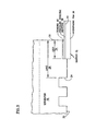
- FIG. 3 is a simplified, fragmentary, schematic representation of the barrier to acid migration of FIG. 2 , in accordance with the present disclosure.
- FIG. 4 is a simplified schematic representation of a sub-scale shunt current rig for permitting rapid evaluation of configurations and materials for preventing acid transfer at edges of fuel cell components.
- FIG. 5 is a graph showing “acid migration rate . . . ” as a function of “aging time” for a separator plate assembly within the FIG. 4 sub-scale shunt current rig.
- FIG. 2 portions of a stack 10 of fuel cells 11 with barriers to acid migration out of the fuel cells are shown in FIG. 2 .
- the simplified schematic of FIG. 2 includes a cathode electrode 12 of a first fuel cell 11 (“Cell 1 ” of FIG. 1 ) and an anode electrode 14 of an adjoining second cell 11 (“Cell 2 ” of FIG. 1 ).
- each fuel cell also includes a matrix 16 containing a liquid acid electrolyte, such as phosphoric acid or fluoroborate acid.
- a separator plate assembly 18 is secured between the cathode electrode 12 of one cell 11 (e.g., Cell 1 ) and the anode electrode 14 of an adjacent cell 11 (e.g., cell 2 ).
- the separator plate assemblies 18 may be made according to the disclosure of a “Fuel Cell Separator Plate Assembly” disclosed in Patent Application Publication No. US 2008/0057373 A1, published on Mar. 6, 2008, or may take the form of a ribbed type of separator plate shown in FIG. 1 of U.S. Pat. No. 4,734,906.
- Each separator plate assembly 18 defines a first flow field 20 , such as a cathode flow field, adjacent a first contact surface 22 of the separator plate assembly 18 .
- the first flow field 20 includes at least one flow channel 24 defined between ribs 26 A, 26 B of the separator plate assembly 18 so that the at least one flow channel 24 extends inwardly from the first contact surface 22 and so that the first contact surface 22 contacts the adjacent cathode electrode 12 to direct an oxidant reactant stream adjacent the cathode electrode 12 .
- the separator plate assembly 18 comprises a land region 28 shown in FIGS. 2 and 3 extending along the first contact surface 22 between an edge 30 of the separator plate assembly 18 and the adjacent flow channel 24 and extending parallel to the flow channels 24 .
- An acid migration barrier 32 is secured within a step 34 defined within the land region 28 of the separator plate assembly 18 .
- the barrier extends from the edge 30 of the separator plate assembly 28 all or a portion of the distance between the edge 30 and the adjacent flow channel 24 .
- the barrier also extends away from the edge of the separator plate assembly a distance of between about 0.051 and about 2.0 millimeters (about 2 and about 80 mils.
- the barrier includes a hydrophobic film 36 , a pressure sensitive adhesive 38 and a bonding agent 40 .
- the hydrophobic film 36 is defined as a polymeric film which has a contact angle of greater than 90° with a liquid electrolyte at cell operating temperature and acid concentration, which has a melting point at least 50° C. (90° F.) above the cell operating temperature, and is chemically stable for 10 years in the environment of the fuel cell stack 10 .
- Suitable barrier film materials include polytetrafluoroethylene (PTFE), fluorinated ethylene propylene (FEP), and polyfluoroaloxy co-polymer resin (PFA).
- the hydrophobic film 36 is equal to or greater than 2 mils (0.05 mm) thick and preferably between 2 mills (0.05 mm) and 5 mils (0.13 mm) thick. Below 2 mils it is too difficult to handle and above 5 mils there are cost and structural issues.
- the pressure sensitive adhesive 38 may be an acrylic or silicone adhesive and is about 0.038 mm (about 1.5 mil) thick.
- the pressure sensitive adhesive 38 is simply an assembly aide and can be of any thickness between 0.5 and 2 mils.
- the hydrophobic film preferably has one surface 44 coated with the PSA.
- the bonding agent 40 may be an elastomer that is compatible in the fuel cell stack 10 and is preferably a fluoroelastomer. Suitable fluoroelastomers include FLUOREL®, VITON®, and FLUOROLAST®. The fluorine content of the fluoroelastomer bonding 40 must be 68% or greater to have acceptable corrosion resistance in a phosphoric acid fuel cell (PAFC). The preferred thickness of the fluoroelastomer is between 0.5-2.0 mils (0.0125-0.05 mm). Below 0.5 mils the bond is inadequate and above 2.0 mil there is a problem with extrusion of the elastomer bonding 40 during the initial heat-up of the stack. The elastomer bonding 40 may be applied to the hydrophobic film 36 , to the PSA 38 or to the surface of the step 34 in the land 28 .
- the geometry of the barrier 32 to acid transfer is dictated by manufacturing tolerances and axial load considerations within the cell stack 10 . If the step 34 extends too far below the contact surface 22 of the land region 28 , there will be too little pressure within an active area of the cell 11 and this will result in increased cell 11 resistance and reactant cross-over due to inadequate compression of the matrix 16 . If the step 34 does not extend far enough below the contact surface 22 of the land region 28 there will be inadequate compression on edge seals (not shown) and reactant leakage will occur.
- the easiest configuration to manufacture is one where a width of the step 34 is equal to a width of the land region 28 . Seal designs where a width of a step is less than that of the land region are acceptable.
- a depth of the step 34 relative to height of a rib 26 A, 26 B should be substantially equal to a thickness of the hydrophobic film 36 . The depth of the step 34 should be 80 to 120 percent of the thickness of the hydrophobic film 36 .
- the elastomer bonding 40 must be cured while the hydrophobic film 36 is compressed against the land region 28 to obtain a good acid barrier 32 .
- the fuel cell stack 10 needs to be heated to above 175° C. for an hour to cure the fluoroelastomer bonding 40 . This can be done in-situ within the fuel cell stack 10 during the first heat-up cycle of the stack 10 .
- the axial force in the land region 28 of the fuel cell is generally in excess of 345 kPa (50 psi), which is more than adequate to create a good seal.
- any of the techniques show in DuPont Technical Bulletin H-55005-2 dated December 1996, such as hot bar heat sealing, may be used to create a bond during the manufacturing process and prior to cell assembly.
- FIG. 4 shows a simplified schematic representation of a sub-scale shunt current rig 50 developed by the inventors herein for permitting relatively rapid evaluation of configurations and materials for preventing acid transfer at edges of fuel cell 11 components.
- the sub-scale shunt current rig 50 includes a separator plate assembly 52 , sandwiched between phosphoric acid filled matrices 54 A, 54 B.
- the acid filled matrices 54 A, 54 B an additional acid filled matrices 74 A, 74 B prevent electronic shorts and gas cross-over between electrode 56 and electrode 58 .
- the objective of the rig 50 is to measure ionic resistance of any electrolyte path on edges 60 of the separator plate assembly 52 .
- Current passing through the cell 62 is an ionic shunt current and is measured as a function of a voltage drop across the cell 62 .
- the cell voltage divided by the current is the ionic resistance of the shunt current path.
- One skilled in the art can convert the ionic resistance to an acid pumping rate for a particular electrolyte, cell design and operating conditions.
- the separator plate assembly 52 is aged at an elevated potential and temperature by placing hydrogen on the electrode 58 and nitrogen on the electrode 56 of the separator plate assembly 52 .
- a potentiostat (not shown) is used to set a potential of the separator plate assembly 52 relative to the electrode 58 potential (hydrogen reference electrode).
- the standard aging condition is 175° C., a water dew point of 54° C. and a potential of 0.875V. This aging condition represents an acceleration factor of about 270 ⁇ for an air inlet edge (not shown) of a phosphoric acid fuel cell (not shown) that operates at about 0.650 volts at 165° C.
- one hour of aging in the sub-scale shunt current rig 50 is equivalent to 270 hours at the air inlet in the cell stack 10 at rated power.
- This aging condition represents an acceleration factor of about 1140 ⁇ for an air exit edge (not shown) of the fuel cell that operates at 0.650 volts at 140° C. Therefore one hour of aging in the rig 50 is equivalent to 1140 hours at the air exit in the cell stack 10 at rated power.
- the sub-scale shunt current rig 50 includes other components including: a first reactant flow field 64 and a second reactant flow field 67 with inlet and exit passages (not shown) for directing flow of the hydrogen, nitrogen and air through the cell 62 ; gold wire 65 connected to the separator plate assembly 52 ; TEFLON® gaskets 66 A, 66 B for sealing the cell 62 ; passageways 72 for directing flow of nitrogen around edges of the separator plate assembly 52 ; a laminated electrolyte reservoir plate (“LERP”) reactant flow field 70 with inlet and exit passages (not shown) secured adjacent the electrode 58 ; and, zirconia cloth layers 74 A, 74 B with a matrix ink secured adjacent opposed surfaces of the separator plate assembly 52 .
- LRP laminated electrolyte reservoir plate
- FIG. 5 shows an acid pumping or “subscale acid migration rate . . . ” as a function of aging time for a separator plate assembly 52 with bare edges 60 .
- the untreated edges 60 start out with a high acid transfer rate that stays high with increasing time as shown at reference numeral 79 in FIG. 5 .
- Tests were also run to establish if curing the bonding agent elastomer 40 prior to assembly of the cell 62 was detrimental.
- Two exemplary separator plate assemblies were made with 0.127 mm (5 mil) thick PTFE film, that extended approximately 0.762 mm (30 mils) beyond the edge 60 , with the PTFE film containing an acrylic PSA, and with about 0.019 mm (0.75 mils) of FLUOROLAST® painted on the land region of the separator plate assembly.
- the FLUOROLAST® in one assembly was cured at 190° C. for two hours without any compression.
- the other assembly was cured within the shunt current rig at 190° C. for two hours under a compressive load of about 100 psi.
- Sub-scale shunt current testing was done with both assemblies and is also shown in FIG. 5 .
- the assembly that was cured under pressure has a low acid transfer rate as shown at reference numeral 78 in FIG. 5 .
- the assembly that was cured without any compression has a higher transfer rate as shown by reference numeral 82 .
- Another separator plate assembly was made with 0.127 mm (5 mil) thick PTFE film, that extended approximately 0.127 mm (5 mils) beyond the edge, that contained an acrylic PSA, with about 0.019 mm (0.75 mils) of FLUOROLAST® painted on the seal region.
- This assembly was cured within the shunt current rig at 190° C. for two hours under a compressive load of about 100 psi. Sub-scale shunt current testing was done.
- the assembly where the PTFE film extended 0.127 mm (5 mils) beyond the edge, as represented by reference numeral 80 in FIG. 5 had a significantly higher acid transfer rate than the assembly where the PTFE extended 0.75 mm (30 mils) 78 as shown in FIG. 5 .
- the barrier 32 may simply protrude beyond the edge 30 of the separator plate assembly, or it may be a formed portion of the separator plate assembly. Care should be taken so that barriers do not interfere with reactant manifold seals (not shown).
- the word “about” is to mean plus or minus ten percent.
Landscapes
- Life Sciences & Earth Sciences (AREA)
- Engineering & Computer Science (AREA)
- Manufacturing & Machinery (AREA)
- Sustainable Development (AREA)
- Sustainable Energy (AREA)
- Chemical & Material Sciences (AREA)
- Chemical Kinetics & Catalysis (AREA)
- Electrochemistry (AREA)
- General Chemical & Material Sciences (AREA)
- Fuel Cell (AREA)
Abstract
Description
Claims (23)
Priority Applications (1)
| Application Number | Priority Date | Filing Date | Title |
|---|---|---|---|
| US13/145,626 US10170783B2 (en) | 2009-04-20 | 2009-06-18 | Manufacture of a fuel cell with liquid electrolyte migration prevention |
Applications Claiming Priority (3)
| Application Number | Priority Date | Filing Date | Title |
|---|---|---|---|
| US21413009P | 2009-04-20 | 2009-04-20 | |
| US13/145,626 US10170783B2 (en) | 2009-04-20 | 2009-06-18 | Manufacture of a fuel cell with liquid electrolyte migration prevention |
| PCT/US2009/003648 WO2010123478A1 (en) | 2009-04-20 | 2009-06-18 | Manufacture of a fuel cell with liquid electrolyte migration prevention |
Publications (2)
| Publication Number | Publication Date |
|---|---|
| US20120028172A1 US20120028172A1 (en) | 2012-02-02 |
| US10170783B2 true US10170783B2 (en) | 2019-01-01 |
Family
ID=43011362
Family Applications (3)
| Application Number | Title | Priority Date | Filing Date |
|---|---|---|---|
| US13/145,626 Active 2031-08-03 US10170783B2 (en) | 2009-04-20 | 2009-06-18 | Manufacture of a fuel cell with liquid electrolyte migration prevention |
| US13/142,099 Active 2030-07-19 US9812724B2 (en) | 2009-04-20 | 2009-06-18 | Preventing migration of liquid electrolyte out of a fuel cell |
| US15/802,599 Active US10396382B2 (en) | 2009-04-20 | 2017-11-03 | Preventing migration of liquid electrolyte out of a fuel cell |
Family Applications After (2)
| Application Number | Title | Priority Date | Filing Date |
|---|---|---|---|
| US13/142,099 Active 2030-07-19 US9812724B2 (en) | 2009-04-20 | 2009-06-18 | Preventing migration of liquid electrolyte out of a fuel cell |
| US15/802,599 Active US10396382B2 (en) | 2009-04-20 | 2017-11-03 | Preventing migration of liquid electrolyte out of a fuel cell |
Country Status (6)
| Country | Link |
|---|---|
| US (3) | US10170783B2 (en) |
| EP (1) | EP2422395B1 (en) |
| KR (2) | KR101719830B1 (en) |
| DE (1) | DE09843753T8 (en) |
| ES (1) | ES2607116T3 (en) |
| WO (2) | WO2010123479A1 (en) |
Families Citing this family (11)
| Publication number | Priority date | Publication date | Assignee | Title |
|---|---|---|---|---|
| US6505123B1 (en) | 2000-07-24 | 2003-01-07 | Weatherbank, Inc. | Interactive weather advisory system |
| WO2012177255A1 (en) * | 2011-06-23 | 2012-12-27 | Utc Power Corporation | Flow field configuration for fuel cell plate |
| US10637080B2 (en) | 2011-10-25 | 2020-04-28 | Doosan Fuel Cell America, Inc. | Acid resistant, monolithic fuel cell cooler assembly |
| KR102055951B1 (en) | 2012-12-28 | 2020-01-23 | 주식회사 미코 | Stack structure for fuel cell |
| KR20150118104A (en) | 2013-02-19 | 2015-10-21 | 두산 퓨얼 셀 아메리카, 인크. | Phosphoric acid fuel cell component having a polymer impregnated region |
| KR102042884B1 (en) * | 2013-02-19 | 2019-11-08 | 두산 퓨얼 셀 아메리카, 인크. | Fuel cell component having a flap extending from a polymer impregnated region |
| US10454239B2 (en) * | 2015-08-28 | 2019-10-22 | International Business Machines Corporation | Wafer scale monolithic integration of lasers, modulators, and other optical components using ALD optical coatings |
| US9923218B2 (en) * | 2015-12-15 | 2018-03-20 | Doosan Fuel Cell America, Inc. | Fuel cell electrolyte management device |
| TWI690921B (en) | 2018-08-24 | 2020-04-11 | 緯創資通股份有限公司 | Sound reception processing apparatus and sound reception processing method thereof |
| US11444298B2 (en) | 2019-07-18 | 2022-09-13 | Hyaxiom, Inc. | Electrolyte shunt migration management in a fuel cell stack |
| US20230197978A1 (en) * | 2021-12-16 | 2023-06-22 | Doosan Fuel Cell America, Inc. | Fuel cell component including polytetrafluoroethylene film bonded to graphite |
Citations (6)
| Publication number | Priority date | Publication date | Assignee | Title |
|---|---|---|---|---|
| US4728533A (en) * | 1982-09-30 | 1988-03-01 | Engelhard Corporation | Process for forming integral edge seals in porous gas distribution plates utilizing a vibratory means |
| US5536598A (en) * | 1994-10-12 | 1996-07-16 | Bipolar Technologies Corporation | Bipolar battery cells, batteries and methods |
| JPH10289722A (en) * | 1997-04-11 | 1998-10-27 | Sanyo Electric Co Ltd | Solid macromolecular type fuel cell and manufacture therefor |
| US20030013004A1 (en) * | 2001-07-02 | 2003-01-16 | Honda Giken Kogyo Kabushiki Kaisha | Fuel cell |
| US20050136322A1 (en) * | 2003-12-22 | 2005-06-23 | Bartling Brandon A. | Tab system for a metal-air electrochemical cell |
| US20050153188A1 (en) * | 2003-12-13 | 2005-07-14 | Elringklinger Ag | Component of a fuel cell unit |
Family Cites Families (13)
| Publication number | Priority date | Publication date | Assignee | Title |
|---|---|---|---|---|
| US4596749A (en) | 1984-08-06 | 1986-06-24 | United Technologies Corporation | Method and apparatus for adding electrolyte to a fuel cell stack |
| JPH0821398B2 (en) * | 1987-12-02 | 1996-03-04 | 三菱電機株式会社 | Stacked fuel cell |
| US5178968A (en) * | 1991-03-18 | 1993-01-12 | International Fuel Cells Corporation | Extruded fuel cell stack shunt current prevention arrangement |
| US5298342A (en) * | 1992-10-20 | 1994-03-29 | M-C Power Corporation | Fuel cell crossover arrestor and pressure seal |
| JPH0837021A (en) * | 1994-07-22 | 1996-02-06 | Fuji Electric Co Ltd | Insulator for phosphoric acid fuel cell stack |
| JPH08190919A (en) * | 1995-01-06 | 1996-07-23 | Fuji Electric Co Ltd | Stacked phosphoric acid fuel cell |
| JPH0935728A (en) * | 1995-07-20 | 1997-02-07 | Fuji Electric Co Ltd | Phosphoric acid laminated fuel cell |
| JP2001185175A (en) * | 1999-12-24 | 2001-07-06 | Honda Motor Co Ltd | Cell for phosphoric acid type fuel cell |
| JP2002015759A (en) * | 2000-06-29 | 2002-01-18 | Honda Motor Co Ltd | Operating method of phosphoric acid fuel cell |
| US20040121200A1 (en) * | 2002-12-24 | 2004-06-24 | Richard Johnsen | Inactive end cell assembly for fuel cells for improved electrolyte management and electrical contact |
| CN100541886C (en) * | 2004-04-13 | 2009-09-16 | 尤米科尔股份公司及两合公司 | Multi-layer membrane-electrode-assembly (ML-MEA) and method for manufacturing the same |
| EP1982372B1 (en) * | 2006-01-17 | 2020-10-21 | Henkel IP & Holding GmbH | Sealant integrated fuel cell components and methods and systems for producing the same |
| US8512907B2 (en) * | 2007-09-27 | 2013-08-20 | Dai Nippon Printing Co., Ltd. | Membrane catalyst layer assembly with reinforcing films, membrane electrode assembly with reinforcing films, and polymer electrolyte fuel cells |
-
2009
- 2009-06-18 ES ES09843753.6T patent/ES2607116T3/en active Active
- 2009-06-18 WO PCT/US2009/003658 patent/WO2010123479A1/en not_active Ceased
- 2009-06-18 DE DE09843753T patent/DE09843753T8/en active Active
- 2009-06-18 WO PCT/US2009/003648 patent/WO2010123478A1/en not_active Ceased
- 2009-06-18 EP EP09843753.6A patent/EP2422395B1/en active Active
- 2009-06-18 US US13/145,626 patent/US10170783B2/en active Active
- 2009-06-18 US US13/142,099 patent/US9812724B2/en active Active
- 2009-06-18 KR KR1020117021602A patent/KR101719830B1/en active Active
- 2009-06-18 KR KR1020117018376A patent/KR101632092B1/en active Active
-
2017
- 2017-11-03 US US15/802,599 patent/US10396382B2/en active Active
Patent Citations (6)
| Publication number | Priority date | Publication date | Assignee | Title |
|---|---|---|---|---|
| US4728533A (en) * | 1982-09-30 | 1988-03-01 | Engelhard Corporation | Process for forming integral edge seals in porous gas distribution plates utilizing a vibratory means |
| US5536598A (en) * | 1994-10-12 | 1996-07-16 | Bipolar Technologies Corporation | Bipolar battery cells, batteries and methods |
| JPH10289722A (en) * | 1997-04-11 | 1998-10-27 | Sanyo Electric Co Ltd | Solid macromolecular type fuel cell and manufacture therefor |
| US20030013004A1 (en) * | 2001-07-02 | 2003-01-16 | Honda Giken Kogyo Kabushiki Kaisha | Fuel cell |
| US20050153188A1 (en) * | 2003-12-13 | 2005-07-14 | Elringklinger Ag | Component of a fuel cell unit |
| US20050136322A1 (en) * | 2003-12-22 | 2005-06-23 | Bartling Brandon A. | Tab system for a metal-air electrochemical cell |
Non-Patent Citations (1)
| Title |
|---|
| Machine translation of patent application publication JP 10-289722, Oct. 27, 1998. * |
Also Published As
| Publication number | Publication date |
|---|---|
| US20120028172A1 (en) | 2012-02-02 |
| DE09843753T8 (en) | 2013-04-25 |
| EP2422395A1 (en) | 2012-02-29 |
| US20180053954A1 (en) | 2018-02-22 |
| KR101632092B1 (en) | 2016-06-20 |
| DE09843753T1 (en) | 2012-09-06 |
| EP2422395A4 (en) | 2013-11-20 |
| US9812724B2 (en) | 2017-11-07 |
| ES2607116T3 (en) | 2017-03-29 |
| KR101719830B1 (en) | 2017-03-24 |
| US10396382B2 (en) | 2019-08-27 |
| WO2010123478A1 (en) | 2010-10-28 |
| US20120028160A1 (en) | 2012-02-02 |
| KR20120049842A (en) | 2012-05-17 |
| KR20120022704A (en) | 2012-03-12 |
| WO2010123479A1 (en) | 2010-10-28 |
| EP2422395B1 (en) | 2016-09-14 |
Similar Documents
| Publication | Publication Date | Title |
|---|---|---|
| US10396382B2 (en) | Preventing migration of liquid electrolyte out of a fuel cell | |
| JP4304101B2 (en) | Electrolyte membrane / electrode structure and fuel cell | |
| JP6616519B2 (en) | Bipolar plate with asymmetric seal forming section and fuel cell stack with such bipolar plate | |
| US7534517B2 (en) | Fuel cell and method for manufacture thereof | |
| JPH11204122A (en) | Solid polymer electrolyte fuel cell | |
| US20100119918A1 (en) | Sealing structure for fuel cell | |
| CN107112562A (en) | Electrochemical cell for fuel cell pack | |
| JP6816620B2 (en) | Fuel cell | |
| CN100391038C (en) | Partition | |
| JP2004207071A (en) | Fuel cell | |
| CA2658980A1 (en) | Fuel cell_having stack fastening load supporting members | |
| CN1538546A (en) | Fuel cell element, fuel cell, fuel cell power generation system, and methods for their manufacture | |
| KR100604700B1 (en) | Fuel cell stack | |
| JP2006339118A (en) | Fuel cell stack assembly equipment | |
| JP2003123801A (en) | Polymer electrolyte stacked fuel cell | |
| US8318362B2 (en) | Fuel cell with electrolyte condensation zone | |
| EP1842258A1 (en) | Fuel cell with electrolyte condensation zone | |
| CN114175321A (en) | Fuel cell unit | |
| JP5139687B2 (en) | Fuel cell | |
| JP2007005222A (en) | Fuel cell and fuel cell separator | |
| US20100136444A1 (en) | Electrical bridge for fuel cell plates | |
| JP2007280615A (en) | Fuel cell seal structure and method of manufacturing the seal | |
| JP2005317518A (en) | Solid polymer fuel cell | |
| JP2018120684A (en) | Separator member for fuel cell | |
| JPH07235318A (en) | Fuel cell |
Legal Events
| Date | Code | Title | Description |
|---|---|---|---|
| AS | Assignment |
Owner name: DOOSAN FUEL CELL AMERICA, INC., GEORGIA Free format text: ASSIGNMENT OF ASSIGNORS INTEREST;ASSIGNOR:CLEAREDGE POWER, INC., CLEAREDGE POWER, LLC, CLEAREDGE POWER INTERNATIONAL SERVICE, LLC;REEL/FRAME:033472/0094 Effective date: 20140718 |
|
| AS | Assignment |
Owner name: UTC POWER CORPORATION, CONNECTICUT Free format text: ASSIGNMENT OF ASSIGNORS INTEREST;ASSIGNORS:KANURI, SRIDHAR V.;BREAULT, RICHARD D.;TENNETI, KISHORE KUMAR;AND OTHERS;SIGNING DATES FROM 20090612 TO 20090615;REEL/FRAME:039338/0987 |
|
| AS | Assignment |
Owner name: CLEAREDGE POWER, LLC, CONNECTICUT Free format text: CERTIFICATE OF CONVERSION;ASSIGNOR:CLEAREDGE POWER CORPORATION;REEL/FRAME:039696/0953 Effective date: 20140121 Owner name: CLEAREDGE POWER CORPORATION, CONNECTICUT Free format text: CHANGE OF NAME;ASSIGNOR:UTC POWER CORPORATION;REEL/FRAME:039696/0973 Effective date: 20130222 |
|
| STCF | Information on status: patent grant |
Free format text: PATENTED CASE |
|
| AS | Assignment |
Owner name: HYAXIOM, INC., CALIFORNIA Free format text: CHANGE OF NAME;ASSIGNOR:DOOSAN FUEL CELL AMERICA, INC.;REEL/FRAME:059364/0046 Effective date: 20220224 |
|
| AS | Assignment |
Owner name: HYAXIOM, INC., CONNECTICUT Free format text: CORRECTIVE ASSIGNMENT TO CORRECT THE THE ASSIGNEE ADDRESS PREVIOUSLY RECORDED AT REEL: 059364 FRAME: 0046. ASSIGNOR(S) HEREBY CONFIRMS THE ASSIGNMENT;ASSIGNOR:DOOSAN FUEL CELL AMERICA, INC.;REEL/FRAME:060062/0957 Effective date: 20220224 |
|
| MAFP | Maintenance fee payment |
Free format text: PAYMENT OF MAINTENANCE FEE, 4TH YEAR, LARGE ENTITY (ORIGINAL EVENT CODE: M1551); ENTITY STATUS OF PATENT OWNER: LARGE ENTITY Year of fee payment: 4 |