US10166567B2 - Coating apparatus and method of coating joint - Google Patents
Coating apparatus and method of coating joint Download PDFInfo
- Publication number
- US10166567B2 US10166567B2 US15/694,328 US201715694328A US10166567B2 US 10166567 B2 US10166567 B2 US 10166567B2 US 201715694328 A US201715694328 A US 201715694328A US 10166567 B2 US10166567 B2 US 10166567B2
- Authority
- US
- United States
- Prior art keywords
- sprayer
- flow path
- pipeline
- coating apparatus
- fluid
- Prior art date
- Legal status (The legal status is an assumption and is not a legal conclusion. Google has not performed a legal analysis and makes no representation as to the accuracy of the status listed.)
- Expired - Fee Related
Links
- 238000000576 coating method Methods 0.000 title claims abstract description 358
- 239000011248 coating agent Substances 0.000 title claims abstract description 344
- 238000000034 method Methods 0.000 title description 114
- 239000007788 liquid Substances 0.000 claims abstract description 194
- 239000012530 fluid Substances 0.000 claims abstract description 182
- 239000007921 spray Substances 0.000 claims abstract description 122
- 238000005507 spraying Methods 0.000 claims abstract description 76
- 238000002360 preparation method Methods 0.000 claims abstract description 19
- 239000002904 solvent Substances 0.000 claims description 78
- 238000011144 upstream manufacturing Methods 0.000 claims description 3
- 239000003517 fume Substances 0.000 claims description 2
- 230000008569 process Effects 0.000 description 80
- 238000002156 mixing Methods 0.000 description 36
- 238000009428 plumbing Methods 0.000 description 27
- 238000010926 purge Methods 0.000 description 21
- 238000011068 loading method Methods 0.000 description 14
- 238000011010 flushing procedure Methods 0.000 description 12
- 230000007246 mechanism Effects 0.000 description 9
- 239000000463 material Substances 0.000 description 6
- 239000003795 chemical substances by application Substances 0.000 description 4
- 238000012545 processing Methods 0.000 description 4
- 230000007613 environmental effect Effects 0.000 description 3
- 239000002184 metal Substances 0.000 description 3
- 239000002245 particle Substances 0.000 description 3
- 238000005086 pumping Methods 0.000 description 3
- 239000007787 solid Substances 0.000 description 3
- 238000005304 joining Methods 0.000 description 2
- 238000012544 monitoring process Methods 0.000 description 2
- 229920000642 polymer Polymers 0.000 description 2
- 230000002411 adverse Effects 0.000 description 1
- 230000004323 axial length Effects 0.000 description 1
- 238000010276 construction Methods 0.000 description 1
- 239000000356 contaminant Substances 0.000 description 1
- 230000006866 deterioration Effects 0.000 description 1
- 230000009977 dual effect Effects 0.000 description 1
- 230000000694 effects Effects 0.000 description 1
- 239000007789 gas Substances 0.000 description 1
- 230000008570 general process Effects 0.000 description 1
- 230000002045 lasting effect Effects 0.000 description 1
- 239000011344 liquid material Substances 0.000 description 1
- 238000004519 manufacturing process Methods 0.000 description 1
- 239000012046 mixed solvent Substances 0.000 description 1
- 239000000203 mixture Substances 0.000 description 1
- 238000012986 modification Methods 0.000 description 1
- 230000004048 modification Effects 0.000 description 1
- 238000013021 overheating Methods 0.000 description 1
- 239000004848 polyfunctional curative Substances 0.000 description 1
- 239000011347 resin Substances 0.000 description 1
- 229920005989 resin Polymers 0.000 description 1
- 230000004044 response Effects 0.000 description 1
- 238000013519 translation Methods 0.000 description 1
Images


Classifications
-
- B—PERFORMING OPERATIONS; TRANSPORTING
- B05—SPRAYING OR ATOMISING IN GENERAL; APPLYING FLUENT MATERIALS TO SURFACES, IN GENERAL
- B05B—SPRAYING APPARATUS; ATOMISING APPARATUS; NOZZLES
- B05B13/00—Machines or plants for applying liquids or other fluent materials to surfaces of objects or other work by spraying, not covered by groups B05B1/00 - B05B11/00
- B05B13/02—Means for supporting work; Arrangement or mounting of spray heads; Adaptation or arrangement of means for feeding work
- B05B13/0207—Means for supporting work; Arrangement or mounting of spray heads; Adaptation or arrangement of means for feeding work the work being an elongated body, e.g. wire or pipe
-
- B—PERFORMING OPERATIONS; TRANSPORTING
- B05—SPRAYING OR ATOMISING IN GENERAL; APPLYING FLUENT MATERIALS TO SURFACES, IN GENERAL
- B05B—SPRAYING APPARATUS; ATOMISING APPARATUS; NOZZLES
- B05B12/00—Arrangements for controlling delivery; Arrangements for controlling the spray area
- B05B12/14—Arrangements for controlling delivery; Arrangements for controlling the spray area for supplying a selected one of a plurality of liquids or other fluent materials or several in selected proportions to a spray apparatus, e.g. to a single spray outlet
- B05B12/1418—Arrangements for controlling delivery; Arrangements for controlling the spray area for supplying a selected one of a plurality of liquids or other fluent materials or several in selected proportions to a spray apparatus, e.g. to a single spray outlet for supplying several liquids or other fluent materials in selected proportions to a single spray outlet
-
- B—PERFORMING OPERATIONS; TRANSPORTING
- B05—SPRAYING OR ATOMISING IN GENERAL; APPLYING FLUENT MATERIALS TO SURFACES, IN GENERAL
- B05B—SPRAYING APPARATUS; ATOMISING APPARATUS; NOZZLES
- B05B13/00—Machines or plants for applying liquids or other fluent materials to surfaces of objects or other work by spraying, not covered by groups B05B1/00 - B05B11/00
- B05B13/02—Means for supporting work; Arrangement or mounting of spray heads; Adaptation or arrangement of means for feeding work
- B05B13/04—Means for supporting work; Arrangement or mounting of spray heads; Adaptation or arrangement of means for feeding work the spray heads being moved during spraying operation
- B05B13/0436—Installations or apparatus for applying liquid or other fluent material to elongated bodies, e.g. light poles, pipes
-
- B—PERFORMING OPERATIONS; TRANSPORTING
- B05—SPRAYING OR ATOMISING IN GENERAL; APPLYING FLUENT MATERIALS TO SURFACES, IN GENERAL
- B05B—SPRAYING APPARATUS; ATOMISING APPARATUS; NOZZLES
- B05B14/00—Arrangements for collecting, re-using or eliminating excess spraying material
-
- B—PERFORMING OPERATIONS; TRANSPORTING
- B05—SPRAYING OR ATOMISING IN GENERAL; APPLYING FLUENT MATERIALS TO SURFACES, IN GENERAL
- B05B—SPRAYING APPARATUS; ATOMISING APPARATUS; NOZZLES
- B05B15/00—Details of spraying plant or spraying apparatus not otherwise provided for; Accessories
- B05B15/50—Arrangements for cleaning; Arrangements for preventing deposits, drying-out or blockage; Arrangements for detecting improper discharge caused by the presence of foreign matter
- B05B15/55—Arrangements for cleaning; Arrangements for preventing deposits, drying-out or blockage; Arrangements for detecting improper discharge caused by the presence of foreign matter using cleaning fluids
-
- B—PERFORMING OPERATIONS; TRANSPORTING
- B05—SPRAYING OR ATOMISING IN GENERAL; APPLYING FLUENT MATERIALS TO SURFACES, IN GENERAL
- B05B—SPRAYING APPARATUS; ATOMISING APPARATUS; NOZZLES
- B05B7/00—Spraying apparatus for discharge of liquids or other fluent materials from two or more sources, e.g. of liquid and air, of powder and gas
- B05B7/16—Spraying apparatus for discharge of liquids or other fluent materials from two or more sources, e.g. of liquid and air, of powder and gas incorporating means for heating or cooling the material to be sprayed
- B05B7/166—Spraying apparatus for discharge of liquids or other fluent materials from two or more sources, e.g. of liquid and air, of powder and gas incorporating means for heating or cooling the material to be sprayed the material to be sprayed being heated in a container
-
- B—PERFORMING OPERATIONS; TRANSPORTING
- B05—SPRAYING OR ATOMISING IN GENERAL; APPLYING FLUENT MATERIALS TO SURFACES, IN GENERAL
- B05C—APPARATUS FOR APPLYING FLUENT MATERIALS TO SURFACES, IN GENERAL
- B05C5/00—Apparatus in which liquid or other fluent material is projected, poured or allowed to flow on to the surface of the work
- B05C5/02—Apparatus in which liquid or other fluent material is projected, poured or allowed to flow on to the surface of the work the liquid or other fluent material being discharged through an outlet orifice by pressure, e.g. from an outlet device in contact or almost in contact, with the work
-
- F—MECHANICAL ENGINEERING; LIGHTING; HEATING; WEAPONS; BLASTING
- F16—ENGINEERING ELEMENTS AND UNITS; GENERAL MEASURES FOR PRODUCING AND MAINTAINING EFFECTIVE FUNCTIONING OF MACHINES OR INSTALLATIONS; THERMAL INSULATION IN GENERAL
- F16L—PIPES; JOINTS OR FITTINGS FOR PIPES; SUPPORTS FOR PIPES, CABLES OR PROTECTIVE TUBING; MEANS FOR THERMAL INSULATION IN GENERAL
- F16L58/00—Protection of pipes or pipe fittings against corrosion or incrustation
- F16L58/18—Protection of pipes or pipe fittings against corrosion or incrustation specially adapted for pipe fittings
-
- B—PERFORMING OPERATIONS; TRANSPORTING
- B05—SPRAYING OR ATOMISING IN GENERAL; APPLYING FLUENT MATERIALS TO SURFACES, IN GENERAL
- B05B—SPRAYING APPARATUS; ATOMISING APPARATUS; NOZZLES
- B05B12/00—Arrangements for controlling delivery; Arrangements for controlling the spray area
- B05B12/14—Arrangements for controlling delivery; Arrangements for controlling the spray area for supplying a selected one of a plurality of liquids or other fluent materials or several in selected proportions to a spray apparatus, e.g. to a single spray outlet
- B05B12/1418—Arrangements for controlling delivery; Arrangements for controlling the spray area for supplying a selected one of a plurality of liquids or other fluent materials or several in selected proportions to a spray apparatus, e.g. to a single spray outlet for supplying several liquids or other fluent materials in selected proportions to a single spray outlet
- B05B12/1427—Arrangements for controlling delivery; Arrangements for controlling the spray area for supplying a selected one of a plurality of liquids or other fluent materials or several in selected proportions to a spray apparatus, e.g. to a single spray outlet for supplying several liquids or other fluent materials in selected proportions to a single spray outlet a condition of a first liquid or other fluent material in a first supply line controlling a condition of a second one in a second supply line
- B05B12/1436—Arrangements for controlling delivery; Arrangements for controlling the spray area for supplying a selected one of a plurality of liquids or other fluent materials or several in selected proportions to a spray apparatus, e.g. to a single spray outlet for supplying several liquids or other fluent materials in selected proportions to a single spray outlet a condition of a first liquid or other fluent material in a first supply line controlling a condition of a second one in a second supply line the controlling condition of the first liquid or other fluent material in the first supply line being its flow rate or its pressure
-
- B—PERFORMING OPERATIONS; TRANSPORTING
- B05—SPRAYING OR ATOMISING IN GENERAL; APPLYING FLUENT MATERIALS TO SURFACES, IN GENERAL
- B05B—SPRAYING APPARATUS; ATOMISING APPARATUS; NOZZLES
- B05B7/00—Spraying apparatus for discharge of liquids or other fluent materials from two or more sources, e.g. of liquid and air, of powder and gas
- B05B7/02—Spray pistols; Apparatus for discharge
- B05B7/04—Spray pistols; Apparatus for discharge with arrangements for mixing liquids or other fluent materials before discharge
- B05B7/0408—Spray pistols; Apparatus for discharge with arrangements for mixing liquids or other fluent materials before discharge with arrangements for mixing two or more liquids
-
- B—PERFORMING OPERATIONS; TRANSPORTING
- B05—SPRAYING OR ATOMISING IN GENERAL; APPLYING FLUENT MATERIALS TO SURFACES, IN GENERAL
- B05B—SPRAYING APPARATUS; ATOMISING APPARATUS; NOZZLES
- B05B7/00—Spraying apparatus for discharge of liquids or other fluent materials from two or more sources, e.g. of liquid and air, of powder and gas
- B05B7/16—Spraying apparatus for discharge of liquids or other fluent materials from two or more sources, e.g. of liquid and air, of powder and gas incorporating means for heating or cooling the material to be sprayed
- B05B7/1693—Spraying apparatus for discharge of liquids or other fluent materials from two or more sources, e.g. of liquid and air, of powder and gas incorporating means for heating or cooling the material to be sprayed with means for heating the material to be sprayed or an atomizing fluid in a supply hose or the like
Definitions
- the present disclosure generally relates to an apparatus for coating pipelines and more particularly to an apparatus for spraying joined end portions of adjacent pipe sections with a liquid coating material.
- Conventional pipelines are formed by arranging separate lengths or sections of pipe end to end and then joining them together. Typically, central portions of each pipe section are coated with an anticorrosion coating during manufacturing and end portions of the pipe section are left uncoated to allow for joining. Pipe sections in a pipeline are often joined together using girth wells. Adjacent end portions of joined pipe sections should be coated with an anticorrosion coating after they are joined. Conventional liquid coating systems spray a coating around the exposed end portions of joined pipe sections in the field.
- Coating systems can include a coating apparatus configured to be selectively mounted on a pipeline near an exposed joint surface.
- a coating apparatus includes a frame that mounts a sprayer for spraying a curable liquid toward the joint surface.
- Frames can include movable frame members that open to install and remove the apparatus from the pipeline and close around the pipe. Operators must be careful when installing and removing the frame from the pipeline. Particularly when removing the frame from the pipeline after coating, it is important to avoid contacting the pipeline and damaging the coating.
- Certain coating apparatuses are configured to rotate around the pipeline to coat the entire circumference of the pipeline at a joint. In general, it is desirable for the frame to close securely around the pipe before spraying to ensure the coating apparatus stays mounted on the pipe as it rotates.
- flushing fluid is dispensed through the spray nozzle to purge contaminants and buildup.
- the flushing fluid can adversely affect the quality of the coating if it is allowed to contact the exposed end portions of the joined pipe sections or the recently sprayed on coating.
- conventional liquid coating systems orient the spray nozzle away from the pipe sections during flushing. After the sprayer has been flushed, the nozzle is repositioned to spray liquid coating material onto the exposed end portions of the joined pipe sections.
- Typical liquid coating materials produce overspray that should be removed from the target area during spraying.
- Coating systems can include process rigs that deliver fluids that form the curable liquid to the coating apparatus.
- day tanks store one or more components of the curable liquid.
- the components of the curable liquid are manually poured into the day tanks prior to spraying. As the day tanks are emptied, the operators must refill the day tanks to continue coating.
- a fluid system connects a process rig to the coating apparatus.
- the fluid system will include various indicators of process conditions, such as temperature, pressure, level, and flow indicators. An operator monitors the indicators and adjusts various components of the system to control the process.
- a coating apparatus for coating a perimeter surface of a pipeline comprises a mounting frame configured to be selectively mounted on the pipeline.
- a sprayer is mounted on the mounting frame and configured to deliver fluid along a flow path oriented toward the perimeter surface of the pipeline when the mounting frame is mounted on the pipeline.
- the sprayer is selectively switchable between operational modes including a preparation mode in which the sprayer delivers a fluid along the flow path to prepare the sprayer for spraying and a spraying mode in which the sprayer sprays the curable liquid along the flow path in a spray pattern.
- a fluid diverter is secured to the mounting frame and is selectively movable relative the sprayer between a fluid diverting position in which the diverter is positioned in the flow path to divert the fluid delivered from the sprayer away from the perimeter surface of the pipeline when the sprayer is operating in the preparation mode and a non-diverting position in which the diverter is not positioned in the flow path to permit free flow of the curable liquid from the sprayer in the spray pattern when the sprayer is operating in the spraying mode.
- a coating apparatus for coating a perimeter surface of a pipeline comprises a mounting frame configured to be selectively mounted on the pipeline.
- a sprayer is mounted on the mounting frame and configured to deliver a fluid along a flow path oriented toward the perimeter surface of the pipeline when the mounting frame is mounted on the pipeline.
- the sprayer is operable in at least one operational mode to deliver the curable liquid along the flow path in a spray pattern.
- the coating apparatus is configured to move the sprayer circumferentially around the pipeline when the sprayer is operating in said at least one operational mode to coat the perimeter surface with the curable liquid.
- a vacuum system is operable to impart a vacuum pressure on a space adjacent the flow path to draw a divertible fluid delivered from the sprayer away from said space.
- An overspray shroud comprises a wall defining a shroud interior and having a sprayer opening and a vacuum opening formed therein.
- the overspray shroud and the sprayer are fixed in position relative one another such that the sprayer is oriented to deliver fluid along the flow path through the sprayer opening and the shroud wall is oriented to substantially contain the delivered fluid within the shroud interior.
- the vacuum system is operatively connected to the vacuum aperture to draw the divertible fluid away from the shroud interior.
- a method of coating a perimeter surface of a pipeline comprises mounting a sprayer on the pipeline to deliver fluid along a flow path oriented toward the perimeter surface of the pipeline.
- a fluid diverter is moved to a fluid diverting position in which the diverter is positioned in the flow path.
- the sprayer is operated in a preparation mode in which fluid delivered to the sprayer to prepare the sprayer for spraying is emitted along the flow path.
- the fluid delivered by the sprayer operating in the preparation mode is diverted away from the perimeter surface of the pipeline using the diverter positioned in the fluid diverting position.
- the diverter is moved from the fluid diverting position to a non-diverting position in which the diverter is not positioned in the flow path.
- the sprayer is operated in a spraying mode in which the sprayer delivers the curable liquid along the flow path in a spray pattern with the diverter positioned in the non-diverting position to coat the perimeter surface of the pipeline.
- a system for coating a perimeter surface of a pipeline comprises a coating apparatus comprising a sprayer configured to spray curable liquid along a flow path.
- a frame supports the sprayer and is configured to selectively mount the sprayer on the pipeline to orient the sprayer so the flow path is oriented toward the perimeter surface of the pipeline and to move the sprayer relative to the pipeline to coat the perimeter surface of the pipeline with the curable liquid.
- a rig located remote from the pipeline comprises one or more containers. Each of the one or more containers contains at least one component of the curable liquid. Plumbing fluidly connects the containers to the sprayer.
- a pump is fluidly connected to the plumbing to pump the at least one component of the curable liquid from the one or more containers through the plumbing to form the curable liquid and to pump the curable liquid through the sprayer, whereby the sprayer sprays the curable liquid along the flow path.
- a heater is operatively connected to the plumbing to heat at least one component of the curable liquid.
- a temperature transmitter is operatively connected to the plumbing to sense a temperature of the at least one component of the curable liquid and to produce a temperature signal representative of the sensed temperature. The temperature transmitter is located at the coating apparatus.
- a controller is operatively connected to the temperature transmitter and the heater to receive the temperature signal from the temperature transmitter and to adjust the heater based on the received temperature signal to adjust the temperature of the at least at least one component of the curable liquid.
- the coating apparatus in a method of controlling the delivery of curable liquid to a sprayer of a coating apparatus, is configured to selectively mount the sprayer on a pipeline to spray the curable liquid along a flow path oriented toward a perimeter surface of the pipeline and to move the sprayer relative to the pipeline to coat the perimeter surface with the curable liquid.
- the method comprises pumping at least one component of the curable liquid from a container located remote from the pipeline through plumbing fluidly connecting the container to the sprayer.
- a temperature signal representative of a temperature of the at least one component of the curable liquid at the coating apparatus is received.
- a heater operatively connected to the plumbing based on the received temperature signal is adjusted to adjust the temperature of the at least one component of the curable liquid.
- the coating apparatus comprises a sprayer configured to spray fluid along a flow path and to be selectively switchable between operational modes including a spraying mode in which the sprayer delivers curable liquid along the flow path and a purge mode in which the sprayer delivers a solvent along the flow path to purge the sprayer.
- the coating apparatus is configured to selectively mount the sprayer on a pipeline to move the sprayer relative to the pipeline while the sprayer is operating in the spraying mode to coat a perimeter surface of the pipeline with the curable polymer.
- the method comprises detecting a solvent level representative of an amount of solvent in a solvent container from which the sprayer receives the solvent. The detected solvent level is compared to a threshold solvent level. The sprayer is permitted to operate in the spraying mode when the detected solvent level is greater than the threshold solvent level. The sprayer is automatically prevented from operating in the spraying mode when the detected solvent level is less than the threshold solvent level.
- a method of evaluating a polymeric coating formed on each of a plurality of perimeter joint surfaces of a pipeline comprises storing in a database spray process data about one or more spray process conditions for each of the joint surfaces.
- the spray process data is received from one or more process sensors of a joint coating apparatus configured to spray each of the perimeter joint surfaces with a curable liquid to form the respective polymeric coating.
- Said one or more process sensors are configured to detect said one or more spray process conditions while the joint coating apparatus sprays each of the perimeter joint surfaces with the curable liquid.
- the spray process data for each of the perimeter joint surfaces is associated with joint identity data which identifies the respective perimeter joint surface in the database.
- a rig for use in delivering a curable liquid to a coating apparatus for coating a perimeter surface of a pipeline comprises a housing defining an interior and having a floor.
- One or more drums are located within the housing. Each of the one or more drums contains a component of the curable liquid.
- a drum support comprises a base fixedly mounted on the floor of the housing. The base comprises a tray defining a secondary liquid containment cavity.
- a liquid-permeable platform is configured to support the one or more drums.
- the platform is slidably mounted on the base to slide relative to the base between a drum loading position and an operational position.
- the platform extends outside of the interior of the housing when positioned in the drum loading position to receive the one or more drums thereupon.
- the platform is positioned above the tray when the platform is in the operational position such that any of the at least one components of the curable liquid contained in the one or more drums that leaks onto the platform passes through the platform and into the secondary liquid containment cavity.
- a coating apparatus for coating a perimeter surface of a pipeline comprises a mounting frame configured to be selectively mounted on the pipeline.
- a sprayer has a spray nozzle configured to deliver fluid along a flow path oriented away from the spray nozzle and flaring outwardly in a fan pattern such that the flow path has a width and the width of the flow path increases as a distance of the flow path from the spray nozzle increases.
- An adjustable sprayer mount mounts the sprayer on the mounting frame for movement relative to the mounting frame.
- the sprayer mount orients the sprayer so that the flow path is oriented toward the perimeter surface of the pipeline when the mounting frame is mounted on the pipeline and is configured to selectively move the sprayer relative to the mounting frame to adjust a distance between the spray nozzle and the exterior surface of the pipeline to thereby adjust the width of the flow path at a location where the flow path intersects the exterior surface of the pipeline.
- a coating apparatus for coating a perimeter surface of a pipeline comprises a sprayer configured to deliver a curable liquid along a flow path.
- a mounting frame is connected to and supports the sprayer and is configured to be selectively mounted on the pipeline to orient the sprayer so that the flow path intersects the perimeter surface of the pipeline.
- the mounting frame comprises a central bracket having a first end portion, a second end portion, and a width extending between the first and second end portions.
- a first end bracket is pivotally connected to the first end portion of the central bracket to pivot relative the central bracket around a first pivot axis.
- a second end bracket is pivotally connected to the second end portion of the central bracket to pivot relative the central bracket around a second pivot axis spaced apart from the first pivot axis.
- the first and second end brackets are selectively pivotable relative the central bracket between a closed position and an open position.
- the mounting frame In the closed position, the mounting frame is shaped and arranged for extending circumferentially around at least a portion the pipeline to mount the coating apparatus on the pipeline.
- the mounting frame In the open position, the mounting frame defines an open gap having a width extending along a gap axis that is wider than the pipeline so that the coating apparatus may be removed from the pipeline with the pipeline passing through the gap along a movement axis generally perpendicular to the gap axis without contacting the mounting frame.
- a coating apparatus for coating a perimeter surface of a pipeline comprises a sprayer configured to deliver a curable liquid along a flow path.
- a mounting frame is connected to and supports the sprayer and is configured to be selectively mounted on the pipeline to orient the sprayer so that the flow path intersects the perimeter surface of the pipeline.
- the mounting frame comprises first and second brackets having interlocking end portions.
- the first and second brackets are selectively movable relative to one another from an open position in which the interlocking end portions are spaced apart from one another to define an open gap sized and arranged to allow the pipeline to pass through the gap and into the mounting frame and a closed position in which the interlocking ends are positioned adjacent to one another such that the mounting frame is sized and arranged to extend circumferentially around the pipeline to mount the coating apparatus on the pipeline.
- a locking mechanism comprises a retaining member at the interlocking end portion of the first bracket.
- a locking member is pivotally connected to the interlocking end portion of the second bracket and is sized and arranged for interlocking engagement with the retaining member.
- the locking member is selectively pivotable around a pivot axis when the first and second brackets are in the closed position from an unlocked position in which the locking member is spaced apart from the retaining member to a locked positon in which the locking member interlockingly engages the retaining member to lock the mounting frame in the closed position.
- FIG. 1 is a schematic elevation of a pipeline
- FIG. 1A is a schematic elevation of a coating system
- FIG. 2 is a fluid schematic of the coating system
- FIG. 3 is a flowchart illustrating the steps and decision blocks of a method of coating a joint
- FIG. 4 is a flow chart illustrating the steps and decision blocks of a method carrying out one of the steps of the method of FIG. 3 ;
- FIG. 5 is a perspective of a coating apparatus of the coating system of FIG. 1 secured to the pipeline;
- FIG. 6 is a front elevation of the coating apparatus with an overspray shroud wall removed
- FIG. 7 is an enlarged perspective of a dispensing subsystem of the coating apparatus including the overspray shroud, a sprayer, and a diverter;
- FIG. 8 is an enlarged fragmentary cross section illustrating the components shown in FIG. 7 and depicting the diverter positioned in a fluid diverting position;
- FIG. 9 is an enlarged fragmentary cross section similar to FIG. 8 illustrating the diverter positioned in a non-diverting position
- FIG. 10 is a perspective of another embodiment of a coating apparatus
- FIG. 11 is a front elevation of the coating apparatus of FIG. 10 in the open position
- FIG. 12 is a front elevation of the coating apparatus of FIG. 10 in the closed position
- FIG. 13 is an enlarged fragmentary perspective of a locking mechanism of the coating apparatus of FIG. 10 in the unlocked position
- FIG. 14 is an enlarged fragmentary perspective of the locking mechanism in the locked position
- FIG. 15 is an enlarged cross section of a sprayer assembly of the coating apparatus of FIG. 10 and the pipeline;
- FIG. 16 is an enlarged perspective of the sprayer assembly
- FIG. 17 is another enlarged perspective of the sprayer assembly illustrating the sprayer in a different position than FIG. 16 relative to a mounting frame of the coating apparatus;
- FIG. 18 is a perspective of a process rig of the coating system
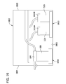
- FIG. 19 is a cross section of the process rig taken in the plane of line 19 - 19 of FIG. 18 ;
- FIG. 20 is similar to FIG. 19 but illustrates a drum support and a vessel support of the process rig in loading positions;
- FIG. 21 is a perspective of the drum support in the loading position.
- a pipeline such as is commonly used for transporting oil and gas is generally indicated at reference number 10 .
- the pipeline 10 includes separately joined pipe sections 10 A- 10 n that are arranged end to end to form the pipeline. Central portions of each of the pipe sections 10 A- 10 n are coated with an anticorrosion coating 12 , but end portions of the pipe sections are uncoated to allow the pipe sections to be joined together to form the pipeline. The thickness of the coating 12 is greatly exaggerated in FIG. 1 so that coated and uncoated portions of the pipeline are easily distinguished.
- the uncoated end portions of the pipe sections 10 A- 10 n are preferably joined together by girth welds at joints 16 .
- the uncoated end portions of the pipe sections 10 A- 10 n define perimeter joint surfaces 14 that extend between adjacent coatings 12 .
- the joint surfaces 14 have direct exposure to environmental conditions, which can cause deterioration of the pipeline 10 if the joint surfaces remain uncoated.
- a coating system 20 is configured to separately coat each of the exposed perimeter joint surfaces 14 with a polymeric coating to protect the pipeline 10 from environmental conditions.
- the major components of the coating system 20 and the overall process by which the coating system coats the exposed perimeter joint surfaces 14 of the pipeline 10 will now be briefly summarized.
- the illustrated coating system 20 includes a crawler 22 fitted with a crane 24 .
- the crawler 22 is attached to a trailer 26 that supports a rig 30 for processing the components of a curable liquid used to coat the perimeter joint surfaces of the pipeline 10 .
- the crawler 22 supports a generator 32 that is operatively connected to the rig 30 to provide power to the rig.
- the rig 30 is operatively connected to a coating apparatus 40 .
- the crane 24 supports the coating apparatus 40 and is configured to selectively mount the coating apparatus on the pipeline 10 at each of the joint surfaces 14 .
- the rig 30 is configured to deliver two-components of a curable liquid to the coating apparatus 40 .
- the rig 30 is also configured to deliver a purging fluid such as a solvent to the coating apparatus 40 to purge residual coating liquid from the coating apparatus after the coating apparatus coats each joint surface 14 with the coating liquid.
- the coating apparatus 40 is configured to mix the two components to from the curable liquid and to spray the curable liquid over the exposed perimeter joint surfaces 14 of the pipeline 10 .
- the trailer 26 supports an air compressor 42 that is operatively connected to the coating apparatus 40 .
- compressed air from the air compressor 42 drives movement of the coating apparatus circumferentially around the pipeline 10 to enable the coating apparatus to spray the curable liquid around the entire circumference of each perimeter joint surface 14 .
- FIG. 1 illustrates the major components of one embodiment of a suitable coating system 10 , it will be understood that other coating systems can use different components without departing from the scope of the invention.
- the general process by which the coating system 20 coats the perimeter joint surfaces 14 of the pipeline 10 begins when the crawler 22 moves the coating system to one of the joint surfaces.
- the crane 24 is used to mount the coating apparatus 40 on the pipeline 10 at the joint surface 14 .
- a control system executes a control routine to separately deliver the two components of the curable liquid from the rig 30 to the coating apparatus 40 at desired process conditions.
- the coating apparatus 40 mixes the two components together to form the curable liquid and sprays the curable liquid along a flow path oriented toward the perimeter joint surface 14 .
- the air compressor 42 delivers compressed air to the coating apparatus 40 that drives rotation of the coating apparatus circumferentially around the pipeline.
- the coating apparatus 40 sprays the curable liquid as it rotates to coat the entire circumference of the perimeter joint surface 14 .
- the process rig 30 delivers solvent (broadly, flushing fluid) to the coating apparatus 40 to flush the curable liquid and keep the coating system from becoming clogged.
- the coating system 20 includes a solvent collection system that automatically reclaims the fluid sprayed through the coating apparatus during flushing.
- the crane 24 removes the coating apparatus 40 from the pipeline, and the crawler 22 moves the coating system 20 to the next joint surface 14 where the process is repeated. It will be understood that various steps of the above-described coating process may be modified with departing from the scope of the invention.
- the fluid system 50 is configured to form the curable liquid from first and second fluid components, which are stored separately in first and second drums 52 A, 52 B located in the rig 30 .
- first and second drums 52 A, 52 B located in the rig 30 .
- the first component stored in the first drum 52 A can be a resin
- the second component stored in the second drum 52 B can be a hardener.
- the two components are mixed together at a suitable volumetric ratio and at suitable process conditions (e.g., temperatures), they form a curable liquid configured for coating the joint surfaces 14 .
- suitable process conditions e.g., temperatures
- the illustrated embodiment uses a two-part curable liquid, it will be understood that other embodiments can use single-component curable liquids or curable liquids mixed together from more than two components without departing from the scope of the invention.
- the fluid system 50 defines first and second parallel flow paths for conveying the first and second components from the first and second drums 52 A, 52 B to a mixing manifold 54 of the coating apparatus 40 .
- the mixing manifold 54 mixes the first and second components together to form the curable liquid.
- components of the coating system 20 that are operatively connected to the first flow path for processing the first component of the curable liquid will be given a reference numeral ending in the letter ‘A’ and components operably connected to the second flow path for processing the second component will be given a reference numeral ending in the letter ‘B.’
- the coating system 20 is configured to switch between several operational modes, including the following: a spray buildup mode in which the process rig 30 builds up a sufficiently large flow of curable liquid in a desired temperature range through the coating apparatus to spray the curable liquid in a desired spray pattern S; a spraying mode in which the coating apparatus sprays the curable liquid to coat a perimeter joint surface 14 ; a recirculation mode in which the coating system 20 recirculates the first and second components of the curable liquid through the fluid system 50 ; and a purge mode in which the coating system delivers a solvent through the coating apparatus to flush residual curable liquid from the coating apparatus.
- a spray buildup mode in which the process rig 30 builds up a sufficiently large flow of curable liquid in a desired temperature range through the coating apparatus to spray the curable liquid in a desired spray pattern S
- a spraying mode in which the coating apparatus sprays the curable liquid to coat a perimeter joint surface 14
- a recirculation mode in which the coating system 20 recirculates the first and
- the coating system 20 When the coating system 20 is operating in the spray buildup and spraying modes, it pumps the first and second components into the mixing manifold 54 , which mixes the components together to form the curable liquid. The coating system 20 further pumps the curable liquid through a sprayer 55 to spray the perimeter surface 14 of the pipeline. When the coating system 20 is operating in the recirculation mode, it pumps the first and second components through portions of the fluid systems that extend between the rig 30 and coating apparatus 40 . But instead of pumping the first and second components through the mixing manifold 54 , the coating system recirculates the first and second components. As explained below, the process rig 30 pumps a solvent through portions of the coating apparatus 40 that come in contact with the curable liquid when operating in the purge mode. Various aspects of the coating system 20 that carry out the spray buildup and spraying modes will be described before turning to the recirculation and purge modes.
- each of the fluid flow paths includes a pump 56 A, 56 B that pumps the respective component from the drum 52 A, 52 B to a day tank 58 A, 58 B.
- the drums 52 A, 52 B are replaceable. New drums 52 A, 52 B replace old drums once the old drums are emptied.
- a level detector (not shown) can be installed in each of the drums 52 A, 52 B to detect emptiness.
- the day tanks 58 A, 58 B are permanently installed in the process rig 30 and are integral and permanent components of the fluid system 50 .
- day tanks can be filled with the components of the curable liquid without using replaceable drums without departing from the scope of the invention.
- the fluid system 50 includes automated temperature control for maintaining the temperature of the fluid components contained in the drums. This ensures the drums 52 A, 52 B deliver the first and second fluid components to the day tanks 58 A, 58 B at proper temperatures for further processing.
- Each drum 52 A, 52 B has a closed loop temperature control system comprising a heater 60 A, 60 B and a temperature transmitter 62 A, 62 B. These temperature control components are preferably refitted onto each new drum 52 A, 52 B as it is installed.
- the transmitters 62 A, 62 B are configured to sense the temperature of the fluid components in the drums 52 A, 52 B and to provide a representative temperature signal to a controller 70 .
- the controller 70 adjusts the heaters 60 A, 60 B to maintain the fluid components in the drums 52 A, 52 B at the desired temperatures.
- the controller 70 is a central controller that runs the control logic for several automated systems of the coating system 20 .
- the controller 70 acts as a single control module for many of the automated systems of the coating system 20 .
- local controllers can separately control discrete control loops such as the temperature control loops that implement the heaters 60 A, 60 B and transmitters 62 A, 62 B.
- any of the automated control systems described herein can be replaced with operator control without departing from the scope of the invention.
- the controller 70 is configured to operate the pumps 56 A, 56 B to deliver fluid from the drums 52 A, 52 B to the day tanks 58 A, 58 B to maintain a desired fluid level in the day tanks.
- the day tanks 58 A, 58 B preferably include level transmitters (not shown) that measure the level of the fluid component contained in each day tank and transmit a respective level signal to the controller 70 .
- the controller 70 uses the level signals to adjust the pumps 56 A, 56 B to maintain the desired fluid levels in the day tanks 58 A, 58 B.
- the day tanks 58 A, 58 B include temperature control for maintaining the fluid components at the desired temperatures.
- Each day tank 58 A, 58 B has a temperature control system comprising a respective temperature transmitter 72 A, 72 B and heater 74 A, 74 B.
- the transmitters 72 A, 72 B are configured to sense and provide a temperature signals representing the temperatures of the first and second fluid components to the controller 70 .
- the controller 70 automatically adjusts the heaters 74 A, 74 B to maintain the fluid components in the day tanks 58 A, 58 B at desired temperatures.
- Pumps 76 A, 76 B installed in the process rig 30 are configured to pump the fluid components from the day tanks 58 A, 58 B through downstream portions of the fluid system 50 .
- the pumps 76 A, 76 B pump the first and second components from the day tanks 58 A, 58 B through an umbilical bundle 80 fluidly connecting the process rig to the coating apparatus 40 and further through plumbing at the coating apparatus.
- the umbilical bundle 80 extends between the rig 30 and the coating apparatus 40 to convey various fluids.
- the umbilical bundle 80 includes a heat trace 82 that can be used to heat the fluids in the umbilical bundle as they flow between the rig 30 and the apparatus 40 .
- heaters 86 A, 86 B are operatively connected to the first and second flow paths at the process rig 30 .
- the heaters 86 A, 86 B are configured to heat the first and second components to desired temperatures for mixing them together and spraying the curable liquid.
- the controller 70 controls the operation of the pumps 76 A, 76 B, and heaters 86 A, 86 B to deliver the first and second components of the curable liquid to the mixing manifold 54 at desired temperatures and desired volume ratios.
- the controller 70 receives several inputs that it uses to control the pumps 76 A, 76 B and heaters 86 A, 86 B.
- a rig pressure transmitter 88 A and a rig temperature transmitter 90 A are operatively connected to the first fluid flow path at the process rig 30 .
- a rig pressure transmitter 88 B and a rig temperature transmitter 90 B are operatively connected to the second fluid flow path at the process rig 30 .
- the fluid system 50 also includes an apparatus pressure transmitter 92 A and apparatus temperature transmitter 94 A operatively connected to the first fluid flow path at the coating apparatus 40 .
- the fluid system 50 includes an apparatus pressure transmitter 92 B and an apparatus temperature transmitter 94 B operatively connected to the second fluid flow path at the coating apparatus 40 .
- the pressure transmitters 88 A, 88 B, 92 A, 92 B are configured to sense the pressures of the first and second fluid components at the rig 30 and coating apparatus 40 , respectively.
- the pressure transmitters 88 A, 88 B, 92 A, 92 B are operatively connected to the controller 70 to transmit pressure signals representative of the sensed pressures to the controller.
- the temperature transmitters 90 A, 90 B, 94 A, 94 B are configured to sense the temperatures of the first and second fluid components at the rig 30 and coating apparatus 40 , respectively.
- the temperature transmitters 90 A, 90 B, 94 A, 94 B are operatively connected to the controller 70 to transmit temperature signals representative of the sensed temperatures to the controller.
- the pumps 76 A, 76 B or other flow sensors are also operatively connected to the controller 70 to transmit pumped volume signals representative of a volume of the first and second component pumped through the fluid system 50 .
- the controller 70 is configured to use the pressure signals, temperature signals, and pumped volume signals to adjust the pumps 76 A, 76 B and heaters 86 A, 86 B to deliver a desired volume of each of the first and second components to the mixing manifold 54 at a desired back pressure and temperature.
- the controller 70 uses a proportional-integral-derivative (PID) control scheme to adjust the operation of the pumps 76 A, 76 B and the heaters 86 A, 86 B.
- PID proportional-integral-derivative
- the pressure, temperature, and pumped volume signals are inputs that the PID control routine uses to derive outputs that adjust the pumps 76 A, 76 B and heaters 86 A, 86 B.
- the controller uses the temperature signals to adjust the heaters 86 A, 86 B to control the temperatures of the first and second fluid components at the mixing manifold 54 .
- the controller 70 uses only the temperature signals from the temperature transmitters 94 A, 94 B to control the heaters 86 A, 86 B.
- the controller can also use the temperature signals from both of the temperature transmitters 90 A, 94 A as inputs in a PID control routine to adjust the heater 86 A to maintain the temperature of the first component.
- the controller can use the temperature signals from one or both of temperature transmitters 90 B, 94 B to adjust the heater 86 B to maintain the temperature of the second component.
- Transmitters 94 A, 94 B provide temperature information close to the point of application of the spray to the pipeline 10 , where temperature is most critical to the effective application of the coating. Depending upon environmental conditions, there may be a substantial effect upon temperature of the components from the rig 30 to the coating apparatus 40 . However, by also monitoring temperature detected at the transmitters 92 A, 92 B and using their signals in the PID algorithm, temperature can be properly controlled to avoid overheating the components at the rig 30 and damage to the heaters 86 A, 86 B caused by hunting. Although the signals from the rig temperature transmitters 90 A, 90 B and the apparatus temperature sensors 94 A, 94 be can be used in suitable embodiments, it is also thought that suitable control can be achieved using only the apparatus temperature sensors as control inputs.
- the controller 70 can also use the volume signals and pressure signals in controlling the pumps 76 A, 76 B.
- the controller 70 controls the pumps 76 A, 76 B to deliver a desired volumetric ratio of the first and second fluid components to the mixing manifold 54 .
- the controller 70 controls the pumps 76 A, 76 B to maintain a desired back pressure in the fluid system 50 so that the curable liquid flows from the sprayer 55 in a desired spray pattern S.
- the controller 70 may receive user input to control the pumps 76 A, 76 B to deliver the first and second fluid components to the mixing manifold 54 at the desired ratio.
- the controller 70 preferably uses the pressure signals from one or both of the pressure transmitters 88 A, 92 A to adjust the pump 76 A to maintain a desired back pressure in the first fluid flow path. Likewise, the controller 70 uses the pressure signals from one or both of the pressure transmitters 88 B, 92 B to control the pump 76 B to maintain a desired back pressure in the second flow path. Like the temperature signals, the controller can suitably use the pressure signals from the rig pressure transmitters 88 A, 88 B and those from the apparatus transmitters 92 A, 92 B in a combined control routine that minimizes hunting while accounting for unexpected pressure variation in the fluid system 50 between the pumps 76 A, 76 B and mixing manifold 54 . Alternatively, the controller 70 can use only the pressure signals from the apparatus pressure transmitters 92 A, 92 B in the control routine.
- the pumps 76 A, 76 B pump the first and second components of the curable liquid through the mixing manifold 54 , which mixes them together to form the curable liquid.
- the pumps further pump the curable liquid through the sprayer 55 to spray the curable liquid in a spray pattern S.
- a pressure sensor 96 and a temperature sensor 98 sense the pressure and temperature of the curable liquid and provide representative pressure and temperature signals to the controller 70 .
- the controller 70 does not use these pressure and temperature signals to control the coating system 20 . Rather, the controller provides these and other data about the process to a database 100 .
- the database 100 stores the process data so that a user can later cross reference process conditions against the quality of joint coatings to determine if changes should be made to the process.
- the coating apparatus 40 is configured to spray the curable liquid over the entire circumference of each perimeter joint area 14 .
- the coating apparatus 40 builds up the fan-shaped spray pattern S described in further detail below.
- the controller 70 can provide command to the controller 70 to begin the spraying mode.
- the sprayer sprays the curable liquid in the fan-shaped spray pattern S.
- the air compressor 42 drives an air motor 102 on the coating apparatus 40 to rotate the coating apparatus around the pipe.
- the controller 70 controls the motor 102 to time rotation with spraying to form an even coating of curable liquid over the joint surface 14 .
- the coating system 20 is configured to minimize overspray as it sprays the curable liquid along the flow path.
- the process rig 30 includes a cyclonic vacuum separator 104 operatively connected to a fluid diverter 106 positioned adjacent the flow path.
- a fluid diverter 106 positioned adjacent the flow path.
- the structure and operation of a suitable fluid diverter will be described in further detail below in reference to an exemplary embodiment of the coating apparatus 40 .
- the separator 104 draws a vacuum through the fluid diverter 106 to draw fluids near the diverter through the vacuum separator.
- the diverter 106 is selectively movable from a position that intersects the flow path of the spray pattern S to a position adjacent the flow path.
- the diverter 106 is positioned in the flow path during the spray buildup mode to block the curable liquid from contacting the joint surface 14 and to draw the curable liquid into the separator 104 .
- the controller 70 moves out of the flow path during the spraying mode, thereby switching the coating system from the spray buildup mode to the spraying mode.
- the vacuum separator 104 draws overspray away from the joint surface 14 through the diverter 106 .
- the separator 104 delivers liquid and solid particles from the sprayer 55 into a reclamation vessel 108 .
- An exhaust fan 110 exhausts gaseous fluids drawn into the separator 104 out of the process rig 30 .
- the controller 70 is configured to selectively switch the coating system 20 from the spraying mode to the recirculation mode.
- the coating apparatus 40 includes a spray valve 112 A, 112 B and a recirculation valve 114 A, 114 B fluidly connected to the fluid system 50 along each of the first and second flow paths.
- the spray valves 112 A, 112 B are open and the recirculation valves 114 A, 114 B are closed to allow the first and second fluid components to flow from the day tanks 58 A, 58 B to the mixing manifold 54 .
- the controller closes the spray valves 112 A, 112 B and opens the recirculation valves 114 A, 114 B.
- the pumps 76 A, 76 B pump the first and second fluid components from the day tanks 58 A, 58 B, through the umbilical bundle 80 and into the coating apparatus 40 .
- the first and second components flow through the open recirculation valves 114 A, 114 B, upstream through the umbilical bundle 80 , and back into the day tanks 58 A, 58 B.
- the recirculation mode therefore, creates separate closed loop flow paths for each of the first and second fluid components.
- Fluid in the recirculation flow paths can be heated by the heaters 74 A, 74 B and 86 A, 86 B to continue to warm the first and second fluid components.
- the recirculation mode can be used to heat the first and second fluid components to a desired temperature before entering the spray buildup or spraying modes.
- the process rig 30 includes a solvent tank 116 .
- the solvent tank 116 is preferably filled with a solvent suitable for flushing curable liquid from the mixing manifold 54 and spray nozzle 55 .
- the controller 70 is configured to selectively switch the coating system 20 to a purge mode in which the coating system delivers solvent from the solvent tank 116 through the mixing manifold 54 and spray nozzle 55 to flush curable liquid from the fluid system 50 .
- a solvent pump 118 is configured to pump solvent from the solvent tank 116 to the coating apparatus 40 through a solvent flow path, which extends through the umbilical bundle 80 .
- the coating apparatus 40 includes first and second solvent valves 120 A, 120 B, which selectively fluidly connect the solvent tank 116 to the end portions of the first and second flow paths, near the mixing manifold.
- first and second solvent valves 120 A, 120 B which selectively fluidly connect the solvent tank 116 to the end portions of the first and second flow paths, near the mixing manifold.
- a single solvent valve could be used, which selectively fluidly connects the solvent tank directly to the mixing manifold.
- the controller 70 is operatively connected to the solvent valves 120 A, 120 B to switch the coating system 20 to the purge mode by opening the solvent valves and closing the spray valves 112 A, 112 B.
- the controller 70 causes the pump 118 to pump solvent into the coating apparatus. Some of the solvent flows through the first solvent valve 120 A and into the portion of the mixing manifold 54 through which the first component of the curable liquid flows in the spraying mode. Another portion of the solvent flows through the second solvent valve 1206 and into the portion of the mixing manifold 54 through which the second component of the curable liquid flows in the spraying mode. The two portions of the solvent mix in the mixing manifold 54 just as the first and second fluid components do in the spraying mode. The solvent pump 118 continues to pump the mixed solvent through the coating apparatus until it passes through the sprayer 55 .
- the fluid system 50 fluidly connects the solvent in the solvent tank 116 to the portion of the plumbing that carries the curable liquid so that the solvent pump 116 can pump the solvent through the plumbing to flush the coating system 20 of curable liquid contained therein.
- the controller 70 is preferably configured to automatically cause the coating system 20 to enter the purge mode after each perimeter joint surface is coated with the curable liquid.
- the coating apparatus 40 remains mounted on the pipeline 10 with the sprayer 55 oriented toward the perimeter joint surface while the coating system flushes the solvent through the coating apparatus.
- the coating apparatus 40 is configured to move the fluid diverter 106 into the solvent flow path F.
- the vacuum separator 104 draws the solvent and flushed curable liquid into the reclamation vessel 108 , and the exhaust fan 110 exhausts gaseous fluids away from the coating system 20 .
- a level sensor 122 is operatively connected to the solvent tank 116 to prevent the coating system 20 from spraying curable liquid when the solvent tank is empty.
- the level sensor 122 detects a solvent level in the solvent tank to determine an amount of solvent therein.
- the level sensor 122 is operatively connected to the controller 70 to provide a level signal representative of the detected amount of solvent in the tank 116 .
- the controller 70 is configured to compare the detected solvent level with a threshold (e.g., a threshold amount of solvent equal to an amount of solvent needed to flush the coating system 20 of curable liquid in the purge mode) before operating the coating system in the spraying mode. If the detected solvent level is greater than the threshold, the controller 70 permits the coating system 20 to operate in the spraying mode. If the detected solvent level is less than the threshold, the controller 70 automatically prevents the coating system 20 from operating in the spraying mode until solvent is added to the tank 116 . For example, the controller can force the coating system 20 into the recirculation mode until the solvent level exceeds the minimum threshold. Moreover, a suitable notification of a low solvent level can be caused to be given by the controller 70 .
- a threshold e.g., a threshold amount of solvent equal to an amount of solvent needed to flush the coating system 20 of curable liquid in the purge mode
- the method 300 begins at step 310 when the coating apparatus 40 is mounted on the pipeline at an uncoated perimeter joint surface 14 .
- the coating system 20 stores joint identity data about the joint surface 14 it is about to coat.
- the joint identity data identifies the joint surface 14 and distinguishes the joint surface from other joint surfaces in the pipeline 10 .
- Suitable joint identity data include global positioning system coordinates for the joint surface 14 , an applicator identifier such as the name of one or more operators of the coating system 20 , application time that identifies the date and time at which the curable liquid is sprayed onto the joint surface, etc.
- the coating system stores process data on the database 100 .
- the process data includes temperature data, pressure data, pumped volume data, valve position data, etc. from the various component devices used in the coating system 20 and described above.
- the coating system 20 stores process data continuously throughout the execution of the method 300 at intervals of, for example about ten seconds.
- the coating system associates the process data with the joint identity data. Then later, the joint coating process conditions can be evaluated by comparing the performance of the joint coatings with the recorded process conditions at which the joints were formed.
- the coating system 20 begins to operate in the recirculation mode.
- the coating system checks to determine whether all start conditions have been met at decision block 316 .
- the coating system checks to ensure there are sufficient amounts of the first and second fluid components in the drums 52 A, 52 B and day tanks 58 A, 58 B.
- the coating system 20 also checks to determine whether the solvent level exceeds a minimum threshold at step 316 .
- the coating system 20 can also, at step 316 , determine whether the first and second fluid components flowing through the fluid system 50 in the recirculation mode are at the desired temperatures and pressures.
- the coating system also determines whether the cyclonic vacuum separator 104 is turned on and whether the coating apparatus 40 is securely mounted on the pipeline 10 before proceeding to the spraying modes.
- the coating system 20 determines that the necessary conditions for spraying have been met at step 316 , it provides an indication to an operator that the system is ready for spraying. At step 318 the operator responds to the indication with a command to begin spraying the perimeter joint surface 14 , and the coating system 20 switches to the spray mode and coats the joint (step 320 ). It is to be understood that switch to the spray mode could be carried out automatically.
- the joint coating step 320 includes the spray buildup mode, spraying mode, and purge mode and is more fully described below in reference to the method 400 of FIG. 4 . As the coating system 20 carries out step 320 , it continuously monitors various parameters such as fluid temperature, back pressure, pumped volumes, etc. (decision block 322 ).
- the coating system 20 notifies the operator at step 324 . If the system 20 maintains the monitored parameters throughout the joint coating step 320 , at step 326 the joint coating process is completed.
- the crane 24 removes the coating apparatus 40 from the pipeline 10 and the crawler 22 moves the coating system 20 to the next perimeter joint surface 14 .
- an exemplary method of coating a joint 400 is suitable for being run during the joint coating step 320 of the method 300 .
- the air motor 102 rotates the coating apparatus 40 around the circumference of the pipe to an initial position (step 402 ).
- the coating system 20 With the fluid diverter 106 positioned in front of the sprayer 55 , the coating system 20 begins to build up the spray pattern S (step 403 ).
- the coating system 20 sprays the curable liquid with the diverter 106 positioned in front of the sprayer 55 until the pressure in and flow rate through the sprayer achieves the desired spray pattern S (e.g., a fan pattern that has a width that increases along with a distance from the sprayer).
- the coating system 20 retracts the diverter 106 . With the diverter 106 retracted, the flow path is oriented toward the exposed perimeter joint surface 14 (step 404 ). At step 406 the air motor 102 begins to rotate the coating apparatus 40 around the circumference of the pipeline 10 (step 406 ).
- the coating system determines whether the coating apparatus 40 has rotated around the pipeline 10 a number of rotations required to achieve the desired coating thickness.
- the coating system 20 continues to spray the curable liquid along the flow path while rotating the apparatus 40 around the pipeline 10 until the desired number of rotations is reached. Then, the coating system 20 stops spraying the curable liquid.
- the coating apparatus rotates to a predefined purge location; and at step 412 , the coating apparatus extends the diverter 106 into the flow path.
- the coating system 20 switches to the purge mode and pumps solvent through the mixing manifold 54 and sprayer 55 to flush the coating apparatus 40 of curable liquid. Once flushing is complete, the motor 102 rotates the coating apparatus 40 to a home position suitable for removing the coating apparatus from the pipeline 10 .
- the illustrated coating system 20 has automated many of the steps of the methods 300 and 400 using the controller 70 .
- the controller 70 automatically executes various steps of the coating methods 300 , 400 in the illustrated embodiment, in other embodiments the steps of the methods can be performed manually without departing from the scope of the invention.
- other embodiments can implement a coating method using different sequences of steps without departing from the scope of the invention.
- FIG. 5 depicts various aspects of an exemplary coating apparatus 40 in greater detail.
- the coating apparatus 40 is shown mounted on the pipeline 10 to coat the exposed perimeter surface 14 of the pipe sections 10 A, 10 B across the girth weld 16 .
- the coating apparatus 40 includes a mounting frame 512 configured to be selectively mounted on the joined end portions of the pipe sections 10 A, 10 B for rotation about the longitudinal axis of the pipeline 10 .
- the mounting frame 512 includes first and second brackets 512 A, 512 B that are selectively pivotable about a hinged connection 514 from an open position (not shown) to a closed position in which the brackets are shaped and arranged for extending around the circumference of the pipeline 10 .
- the coating apparatus includes two pairs of drive wheels 516 , 518 and the air motor 102 .
- the air motor 102 receives compressed air routed from the air compressor 42 through a pneumatics control box 520 .
- the air motor 102 uses the compressed air to drive rotation of the drive wheels 516 , 518 to rotate the coating apparatus 40 circumferentially around the pipeline 10 .
- Other types of drive motors can also be used without departing from the scope of the invention.
- the drive wheels 516 , 518 and a third pair of wheels 522 which are not driven, contact the exterior of the pipeline 10 to guide the apparatus 40 on the pipeline as it rotates.
- the coating apparatus 40 can rotate at least one complete revolution around the circumference of the pipeline.
- the controller 70 communicates with the drive motor 102 to automatically direct the motor to rotate the coating apparatus 40 around the pipeline 10 .
- the coating apparatus 40 sprays a curable liquid on the exposed perimeter surface 14 of the pipeline 10 as the apparatus rotates to coat the joined end portions of the pipe sections 10 A, 10 B.
- the sprayer 55 is mounted on the mounting frame 512 and configured to deliver fluid along the flow path F toward the exposed perimeter surface 14 of the pipeline 10 .
- the sprayer is a GRACO AL Series Automatic Sprayer, available from GRACO Inc. of Minneapolis, Minn.
- the coating apparatus uses other sprayers without departing from the scope of the invention.
- a shroud 532 substantially surrounds the spray pattern S to prevent overspray.
- the shroud 532 has been partially broken away to reveal a flow path F of the spray and show more of the sprayer 55 .
- the overspray shroud 532 includes a shroud wall surrounding the flow path F and defining a shroud interior.
- the shroud 532 has an open bottom (as the shroud is oriented in FIGS. 4-6 ) that permits spray to pass out of the shroud onto the pipeline 10 .
- the shroud wall 532 defines a sprayer opening 533 and a vacuum/diverter opening 535 .
- the overspray shroud 532 and the sprayer 55 are fixed in position relative one another such that the sprayer is oriented to deliver fluid along the flow path F through the sprayer opening 533 .
- the wall of the shroud 532 is shaped and arranged to substantially contain the delivered fluid within the shroud interior.
- the sprayer opening 533 is aligned with the sprayer 55 and flow path F so that the sprayer delivers fluid along the flow path through the sprayer opening.
- the vacuum/diverter opening 535 is sized to receive the diverter 106 for selectively obstructing fluid flow along the flow path F.
- the vacuum/diverter opening 535 is shaped and arranged to couple the shroud interior to a vacuum pressure that draws overspray out of the interior of the shroud.
- vacuum opening and “diverter opening” will be used interchangeably to refer to the vacuum/diverter opening 535 throughout this disclosure.
- mounting bracket 534 fixedly mounts the sprayer 55 on the second mounting frame 512 .
- the sprayer 55 does not move relative to the apparatus.
- the flow path F is oriented in a fixed direction relative to the apparatus and moves conjointly with the apparatus.
- the sprayer 55 is configured to selectively switch between different operational modes in which the sprayer delivers different types of fluid along a flow path F. In each of the operational modes, the flow path F is oriented toward the exposed perimeter surface 14 of the pipeline 10 . But in different operational modes, the sprayer 55 can, in some embodiments, deliver fluids along the flow path F in different dispensing patterns.
- the sprayer 55 delivers fluid along the flow path F in a spray pattern S in which the delivered fluid fans out across the entire axial length of the perimeter surface 14 between the coatings 12 ( FIG. 1 ) so that the pipe sections are continuously coated after spraying is complete.
- the shroud 532 is shaped and arranged to be spaced apart from the fluid the sprayer 55 delivers along the flow path F.
- the shroud 532 is shaped like a long and narrow box to allow for substantially unobstructed spray of the coating liquid along the flow path F in a wide, fan-like spray pattern which spans the length of the exposed perimeter surface 14 of the pipeline 10 .
- the sprayer 55 may require a fan buildup mode to build sufficient fluid flow to achieve the desired spray pattern.
- the sprayer 55 can deliver fluids along the flow path F with different dispensing patterns.
- the sprayer 55 is configured to deliver different types of fluid along the flow path F depending on the operational mode.
- the apparatus 40 includes the mixing manifold 54 for mixing together fluids of different types before delivering them through the sprayer 55 .
- the coating apparatus 40 is shown with the hoses that connect the mixing manifold 54 and sprayer 55 removed for clarity.
- the mixing manifold 54 is operatively connected to a plurality of fluid sources, such as the day tanks 58 A, 58 B and solvent tank 116 .
- the mixing manifold 54 can also be connected to other fluid sources without departing from the scope of the invention.
- the process rig 30 pumps curable liquid components and solvent through the mixing manifold 54 and sprayer 55 .
- the coating apparatus could, instead, use a local pump system and/or local fluid containers without departing from the scope of the invention.
- the spraying system is configured to switch between several operational modes, including a spraying mode.
- the coating apparatus 40 is configured to operate in the spraying mode to deliver the curable liquid in a spray pattern along the flow path F to coat the exposed perimeter joint surface 14 of the pipeline 10 .
- the motor 120 drives apparatus 40 in rotation around the circumference of the pipeline 10 so that the sprayer delivers a substantially uniform coating over the exposed perimeter surface 14 .
- the controller 70 sequences the operation of the sprayer 55 in the spraying mode with the operation of the drive motor 102 to cover the exposed perimeter surface 14 with a substantially uniform coating of curable liquid material, which cures to form an anticorrosion coating on the pipeline 10 .
- Operational modes other than the spraying mode in which fluid flows through the sprayer 55 can generally be referred to as “preparation modes” because they each are used to prepare the coating apparatus for operating in the spraying mode at some future time.
- preparation modes For example, in the purge mode, the coating system 20 prepares the sprayer 55 for spraying by flushing residual curable liquid from the sprayer.
- spray buildup mode the coating system 20 prepares the sprayer 55 for spraying by building up a fan pattern suitable for coating the joint surface 14 with the curable liquid.
- the sprayer 55 delivers fluid, such as solvent or curable liquid that is not used in coating the pipeline 10 along the flow path F.
- the sprayer 55 Because the sprayer 55 is fixed in position relative to the mounting frame 512 , the sprayer directs the fluid toward the perimeter surface 14 of the pipeline 10 in the preparation mode just as in the spraying mode.
- the application of fluid to the perimeter surface 14 of the pipeline 10 either before or after spraying the pipeline with the curable liquid can damage the resulting coating.
- the coating apparatus 40 is configured to divert the fluid away from the exposed surface 14 of the pipeline 10 to prevent damage to the coating.
- the fluid diverter 106 is configured to divert fluid dispensed along the flow path F in the preparation mode.
- the fluid diverter 106 is movably secured to the mounting frame 512 .
- the fluid diverter 106 is movable relative to the sprayer 55 between a fluid diverting position ( FIG. 8 ) and a non-diverting position ( FIG. 9 ).
- the diverter 106 intersects in the flow path F to divert the fluid away from the perimeter surface 14 of the pipeline 10 .
- the controller 70 preferably automatically positions the fluid diverter 106 in the fluid diverting position when the sprayer 55 operates in the preparation mode. In the non-diverting position shown in FIG.
- the diverter 106 is spaced apart from the flow path F to permit free flow of fluid from the sprayer toward the exposed perimeter surface 14 .
- the controller 70 preferably automatically positions the diverter 106 in the non-diverting position when the sprayer 55 operates in the spraying mode to permit free flow of the curable liquid to the perimeter surface 14 .
- the diverter 106 is movable along a diverter movement axis A between the fluid diverting and non-diverting positions. It will be understood, that a fluid diverter may be movable in other ways (e.g., by pivoting, etc.) without departing from the scope of the invention.
- the diverter movement axis A extends transverse (e.g., generally perpendicular) to the flow path F.
- the diverter 106 extends through the diverter opening 535 in the side wall of the shroud 532 and moves along the movement axis A through the opening between the fluid diverting and non-diverting positions. In both the fluid diverting and non-diverting positions, the inner axial end of the diverter 106 is positioned within the interior of the shroud 532 .
- the coating apparatus 40 includes a diverter guide 552 oriented parallel to the diverter movement axis A.
- the diverter guide 552 defines a guide channel, and a slide 554 is slidingly received in the guide channel.
- the diverter 106 is mounted on the slide 554 and is thereby received in the diverter guide 552 for movement along the diverter movement axis A.
- a mounting bracket 556 fixedly mounts the diverter guide 552 on the overspray shroud 532 .
- a pneumatic cylinder 558 ( FIG.
- the controller 70 is operatively connected to the pneumatic cylinder 558 to time actuation of the cylinder to automatically position the diverter 106 in the fluid diverting position during the preparation mode and in the non-diverting positon during the spraying mode.
- the illustrated diverter 106 is tube-shaped.
- the diverter 106 has inner and outer axial ends and an annular side wall 551 extending along a longitudinal axis oriented parallel to the diverter movement axis A.
- the side wall 551 of the diverter 106 defines a lumen 553 .
- An inner axial end wall 560 bounds an inner end of the lumen 553 , and the lumen extends through the open outer axial end of the diverter 106 .
- an aperture 562 is formed in the side wall of the diverter 106 adjacent the inner axial end wall 560 .
- the aperture 562 is positioned in the flow path F and opposes the sprayer 55 such that the fluid delivered from the sprayer is delivered through the aperture and into the lumen 553 .
- the illustrated diverter 106 collects diverted fluid in the interior lumen 553 .
- the diverter 106 is operatively connected to the cyclonic vacuum separator 104 (broadly, a vacuum system), which is adapted to draw a vacuum through the interior lumen 553 of the tube.
- the vacuum system 104 can be a vacuum pump or other apparatus that is mounted on the mounting frame 512 or is located remote from the pipeline 10 .
- the vacuum system 104 is preferably operatively connected to the open outer end of the diverter 106 to impart a vacuum pressure on the interior lumen 553 .
- the vacuum pressure is operative to draw the diverted fluid through the tube.
- the fluid flows along a first portion of the fluid flow path F, through the aperture 562 , and into the diverter lumen 553 , where the vacuum pressure draws the fluid out of the diverter 106 and into the vacuum system 104 .
- the vacuum separator 104 deposits liquid and solid particles in a reclamation vessel 108 and the exhaust fan 110 exhausts gaseous fluids away from the coating system 20 .
- the vacuum system 104 is also operative to draw any overspray of curable liquid away from the interior of the shroud 532 during the spraying mode.
- the inner axial end of the tube extends through the diverter opening 535 in the shroud 532 and into the shroud interior.
- the diverter 106 is shaped and arranged in the non-diverting position so that the aperture 562 is located within the interior of the shroud 532 .
- the vacuum system 104 is operative to draw overspray of the curable liquid through the aperture 562 , into interior lumen 553 of the diverter 106 , and away from the shroud interior.
- the vacuum separator 104 deposits liquid and solid particles in the reclamation vessel 108 and the exhaust fan 110 exhausts gaseous fluids away from the coating system 20 .
- the illustrated embodiment employs a dual purpose diverter 106 that functions to draw in overspray during the spraying mode.
- the vacuum system may impart a vacuum pressure on a space adjacent the flow path to draw in overspray in other ways without departing from the scope of the invention.
- the crane 22 mounts the apparatus 40 on the pipeline 10 so that the sprayer 55 is oriented toward the perimeter surface 14 of the pipeline.
- the controller 70 automatically directs the pneumatic cylinder 558 to move the diverter 106 to the fluid diverting position ( FIG. 8 ).
- the controller 124 then operates the sprayer 55 in the fan buildup mode to build up a fan-shaped spray pattern.
- the diverter 106 diverts the flushing fluid away from the perimeter surface 14 of the pipeline 10 and the vacuum system 104 draws the diverted fluid away from the coating apparatus.
- the controller 70 directs the pneumatic cylinder 558 to move the diverter 106 from the fluid diverting position to the non-diverting position ( FIG. 9 ). With the diverter 106 in the non-diverting position, the controller 70 switches the coating system 20 to the spraying mode and sprays the curable liquid over the perimeter joint surface 14 as the coating apparatus 40 rotates.
- the vacuum system 104 draws a vacuum through the diverter 106 , to remove overspray during spraying.
- the controller 70 returns the diverter 106 to the diverting position and operates the sprayer 55 in the purge mode to flush curable liquid out of the sprayer.
- the vacuum separator 104 draws the sprayed solvent through the diverter 106 and away from the perimeter joint surface 14 .
- the illustrated coating apparatus 40 sprays an exposed surface of a pipeline 10 in a controlled manner.
- the apparatus 40 functions in multiple fluid delivery modes to ensure uniform spraying of curable liquid when the exposed pipeline surface 14 is being coated.
- the movable diverter 106 allows flushing fluids to be diverted away from the surface 14 of the pipeline 10 without moving of the sprayer 55 .
- the diverter 55 functions in two capacities to dispose of flushing fluids and gaseous fumes associated with the curable coating material.
- FIG. 10 another embodiment of a coating apparatus suitable for use in the coating system 20 is generally indicated at reference number 1040 .
- the coating apparatus 1040 is similar in many respects to the coating apparatus 40 .
- Features of the coating apparatus 1040 that correspond with features of the coating apparatus 40 are given the same reference number, plus 1000.
- the coating apparatus 1040 includes a mounting frame 1512 configured to selectively mount a sprayer 1055 on the pipeline 10 so that a flow path F ( FIG. 15 ) intersects an exposed perimeter joint surface 14 of the pipeline.
- a mixing manifold 1054 is mounted on the frame 1512 and is configured to be fluidly connected to the process rig 30 like the mixing manifold 54 .
- the manifold 1054 is configured to mix the first and second components together to form the curable liquid and to provide the curable liquid to the sprayer 1055 .
- a drive motor 1102 is mounted on the mounting frame 1512 and operatively connected to the air compressor 42 .
- the drive motor 1102 drives rotation of wheels 1518 , which are all driven wheels in certain embodiments.
- the wheels 1518 contact the pipeline 10 to rotate the coating apparatus 1040 around the pipeline as the sprayer 1055 sprays the curable liquid over the exposed perimeter joint surface 14 .
- the mounting frame 1512 includes a central bracket 1512 A and first and second end brackets 1512 B, 1512 C pivotally secured to the central bracket.
- Each of the brackets 1512 A, 1512 B, 1512 C comprises parallel plate members. Bracing rods extend between the parallel plate members and fix the parallel plate members in spaced apart relationship.
- the central bracket 1512 A has a first end portion near the first end bracket 1512 B, a second end portion near the second end bracket 1512 C, and a width extending between the first and second end portions.
- the first end bracket 1512 B has a pivoting end portion pivotally connected to the first end portion of the central bracket 1512 A at a pivoting connection 1514 B.
- the first end bracket 1512 B also has a width that extends from the pivoting end portion to an opposite interlocking end portion.
- the second end bracket 1512 C has pivoting end portion pivotally connected to the second end portion of the central bracket 1512 A at a pivoting connection 1514 C.
- the second end bracket 1512 C also has a width that extends from the pivoting end portion to an opposite interlocking end portion adjacent the interlocking end portion of the first end bracket 1512 B.
- the first and second end brackets 1512 B, 1512 C are connected to the central bracket 1512 A to pivot about first and second pivot axes A 1 , A 2 , respectively. As shown in FIGS. 11 and 12 , the first and second end brackets 1512 B, 1512 C are selectively pivotable about the first and second pivot axes A 1 , A 2 relative the central bracket 1512 A between an open position ( FIG. 11 ) and a closed position ( FIG. 12 ). As will be discussed in further detail below, when the first and second end brackets 1512 B, 1512 C are in the closed position, the interlocking end portions are configured for selective interlocking engagement to secure the mounting frame 1512 on the pipeline 10 .
- the coating apparatus 1040 is configured to pivot between the open and closed positions under pneumatic power.
- Two pneumatic cylinders 1515 are operatively connected to the mounting frame 1512 between the central bracket 1512 A and the first end bracket 1512 B to pivot the first end bracket between the open and closed positions.
- Two other pneumatic cylinders 1515 are operatively connected to the mounting frame 1512 between the central bracket 1512 A and the second end bracket 1512 C to pivot the second end bracket between the open and closed positions.
- the controller 70 is preferably operable connected to the pneumatic cylinders 1515 to drive the cylinders to open and close the mounting frame 1512 in response to operator commands.
- the mounting frame 1512 defines an open gap 1517 .
- the open gap 1517 has a width W 1 extending along a gap axis A 3 that is wider than the pipeline 10 .
- the coating apparatus 1040 may be installed on or removed from the pipeline 10 , whereby the pipeline passes through the gap 1517 without contacting the frame. More specifically, the pipeline 10 can pass through the gap 1517 without contacting the frame 1512 by moving the coating apparatus 1040 along a gap movement axis A 4 perpendicular to the gap axis A 3 .
- the mounting frame 1512 can be pneumatically opened to have a wide pipeline receiving gap 1517 .
- the mounting frame 1512 can be pneumatically opened to have a wide pipeline receiving gap 1517 .
- the mounting frame 1512 in the closed position, is shaped and arranged for extending circumferentially around the pipeline 10 to mount the coating apparatus 1040 on the pipeline.
- the mounting frame 1512 extends around the entire circumference of the pipeline.
- the interlocking end portions of the first and second end brackets 1512 B, 1512 C are positioned adjacent one another opposite the central bracket 1512 A.
- the illustrated embodiment is shaped and arranged to extend substantially around the entire circumference of the pipeline in the closed position, it will be understood that other mounting brackets can extend around less than the entire circumference of a pipeline without departing from the scope of the invention. As shown in FIG.
- the mounting frame 1512 is preferably shaped and arranged to automatically position the drive wheels 1518 in contact with the pipeline 10 when the mounting frame 1512 is closed around the pipeline. This ensures the drive motor 1102 can drive rotation of the coating apparatus 1040 around the pipeline during spraying.
- the illustrated coating apparatus 1040 includes a locking mechanism 1511 configured to selectively lock the mounting frame 1512 is in the closed position.
- the locking mechanism 1511 includes a retaining shaft 1521 (broadly, a retaining member) that is fixed to the interlocking end portion of the first end bracket 1512 B.
- the retaining shaft 1521 extends between the plate members forming the first end bracket 1512 B.
- retaining members can have other configurations without departing from the scope of the invention.
- the locking mechanism 1511 also includes plurality locking hooks 1523 (each, broadly a locking member). The locking hooks 1523 are configured to lockingly engage the retaining shaft to secure the mounting frame 1512 in the closed position on the pipeline 10 .
- the locking hooks 1523 are pivotally connected to the interlocking end portion of the second end bracket 1512 C.
- the locking hooks 1523 are spaced apart along a pivoting shaft 1525 extending between the two plate members forming the second end bracket 1512 B.
- the pivoting shaft 1525 is pivotally mounted on the mounting frame 1512 to pivot about a pivot axis A 5 .
- the pivoting shaft 1525 and the retaining shaft 1521 extend along parallel axes in the illustrated embodiment.
- the locking hooks 1523 are selectively pivotable around the pivot axis A 5 from an unlocked position ( FIG. 13 ) in which the locking hooks are spaced apart from the retaining shaft 1521 to a locked position ( FIG. 14 ) in which the locking hooks lockingly engage the retaining shaft.
- Each of the locking hooks 1523 has hook end and an opposite free end. Each hook end is sized and arranged for interlockingly engaging the retaining shaft 1521 .
- the locking hooks 1523 are fixedly mounted on the pivoting shaft 1525 , and the pivoting shaft is configured to pivot around the pivot axis A 5 , which is collocated with the central longitudinal axis of the pivoting shaft.
- the locking hooks could be pivotally mounted on the pivot shaft to pivot around a pivot axis without departing from the scope of the invention.
- the pivot shaft could also be pivotally mounted on one or more pivot arms that pivot about a pivot axis spaced apart from the central longitudinal axis thereof without departing from the scope of the invention.
- a pneumatic cylinder 1527 is operatively connected to an attachment shaft 1529 that is attached to the free ends of the locking hooks 1523 .
- the pneumatic cylinder 1527 When the pneumatic cylinder 1527 is actuated, it drives the attachment shaft 1529 and locking hooks 1523 in rotation about the pivot axis A 5 to pivot the hooks between the locked and unlocked positions.
- the controller 70 is operatively connected to the pneumatic cylinder 1527 to selectively actuate the cylinder to move the locking hooks 1523 about the pivot axis A 5 between the locked and unlocked positions.
- the sprayer 1055 is configured to spray the curable liquid toward the perimeter joint surface 14 along a flow path F that widens as the curable liquid travels away from the sprayer.
- the sprayer 1055 has a spray nozzle 1057 .
- the sprayer 1055 delivers the curable liquid along the flow path F so the fluid flow is oriented away from the spray nozzle 1057 .
- the flow path F has a spray pattern that flares outwardly in a fan pattern such that the flow path has a width W 2 .
- the width W 2 of the flow path F increases as a distance D of the flow path from the spray nozzle 1057 increases.
- the sprayer 1055 is capable of coating different widths of the pipeline 10 with the curable liquid depending on the distance between the spray nozzle 1057 and perimeter surface 14 .
- the coating apparatus 1040 is configured to adjust the distance D between the spray nozzle 1057 and the perimeter surface 14 to adjust the width W 2 of the pipeline 10 the coating apparatus sprays with the curable liquid.
- the illustrated coating apparatus includes an adjustable sprayer mount 1611 .
- the sprayer mount 1611 mounts the sprayer 1055 and shroud 1532 on the mounting frame 1512 for movement relative to the mounting frame.
- the sprayer mount 1611 orients the sprayer 1055 so that the flow path F is oriented toward the perimeter surface 14 of the pipeline 10 when the mounting frame is mounted on the pipeline ( FIG. 15 ).
- FIGS. 16 and 17 show that as shown by comparison of FIGS.
- the sprayer mount 1611 is configured to selectively move the sprayer 1055 relative to the mounting frame 1512 to adjust the distance D between the spray nozzle 1057 and the exterior surface of the pipeline to thereby adjust the width Ws of the flow path F at the location where the flow path intersects the exterior surface 14 of the pipeline.
- the sprayer mount comprises a threaded shaft 1613 and a pair of threaded guide collars 1615 threadably mated to the threaded shaft.
- the threaded shaft 1613 is mounted on the mounting frame 1512 for rotation relative to the mounting frame, but is prevented from moving in translation relative to the mounting frame along its longitudinal axis.
- the guide collars 1615 are threaded onto the shaft 1613 and fixedly mounted on the overspray shroud 1532 .
- the sprayer 1055 is also fixedly mounted on the overspray shroud 1532 .
- An adjustment knob 1617 is fixed to the free end of the shaft 1613 to allow a user to rotate the threaded shaft.
- the threaded shaft 1613 rotates in the guide collars 1615 , which causes the guide collars to translate relative the shaft along its longitudinal axis.
- the shroud 1532 and sprayer 1055 move conjointly with the guide collars 1615 and relative to the perimeter joint surface 14 of the pipeline 10 .
- a user can adjust the distance D between the spray nozzle 1057 and the perimeter joint surface 14 and thereby adjust the width Ws of the spray pattern S at the joint surface by rotating the knob 1617 .
- the illustrated embodiment uses a threaded shaft mounted on the mounting frame and threaded collars monted on the sprayer assembly to form the movable sprayer mount, it will be understood that other embodiments can use other movable sprayer mounts to adjust the width of the sprayed-on coating without departing from the scope of the invention.
- the distance adjustment could be automated without departing from the scope of the invention.
- the sprayer 1055 and shroud 1532 are supported as they move relative to the mounting frame 1512 .
- the coating apparatus 1040 includes non-threaded support shafts 1619 oriented parallel to the threaded shaft 1613 .
- the support shafts 1519 are mounted on the base frame 1512 .
- Each of the support shafts 1619 is slidably received in a pair of non-threaded support collars 1621 that is fixed to the shroud 1532 .
- the support collars 1621 slide along the support shafts 1619 to support the shroud 1532 as it moves.
- the process rig 30 includes a housing 1802 that has a front end 1803 , a rear end 1804 , and a floor 1805 .
- the housing 1802 defines a process rig interior 1808 .
- the process rig interior 1806 receives various components of the fluid system 50 , such as the day tanks 52 A, 52 B, pumps 76 A, 76 B (not shown in FIG. 18 ), and associated plumbing.
- the process rig housing 1802 is also configured to receive the replaceable fluid component drums 52 A, 52 B.
- the components of a curable liquid are manufactured and stored in large drums (e.g., 55-gallon drums) that are difficult to transport and store.
- the term “drum” will refer to any suitable movable container for storing one or more components of a curable liquid.
- the illustrated process rig 30 includes drum fittings 1810 A, 1810 B that can be fitted over the open top ends of new drums as they are replaced.
- the fittings 1810 A, 1810 B fluidly connect the drums 52 A, 52 B to the fluid system 50 so that the pumps 56 A, 56 B can pump the first and second fluids into the day tanks 58 A, 58 B. Once the pumps 56 A, 56 B pump out all of the fluid contained in one of the drums 52 A, 52 B, the empty drum can be removed and a new drum can be installed.
- the process rig 30 includes a movable drum support 1820 , which simplifies the process of replacing the drums 52 A, 52 B.
- the illustrated drum support 1820 comprises a base 1822 and a movable platform 1824 .
- the base 1820 is fixedly mounted on the floor 1805 of the process rig housing 1802 near the front end 1803 .
- the base 1820 includes an outer base frame 1826 and an inner tray 1828 .
- the base frame 1826 supports guide rails 1830 that guide movement of the platform 1824 relative to the base 1822 .
- the tray 1828 defines a secondary liquid containment cavity 1832 for receiving any liquid that is spilled from either of the drums 52 A, 52 B in use ( FIG. 19 ).
- the platform 1824 is configured to support the drums 52 A, 52 B.
- the platform 1824 includes an outer frame 1840 , which is slidably mounted on the base 1822 .
- the platform 1824 rotatably mounts guide rollers (not shown) that are received in the guide rails 1830 . As the platform 1824 slides relative to the base 1822 , the guide rollers roll along the guide rails 1830 to guide the movement of the platform.
- the platform 1824 is liquid-permeable.
- the platform comprises a metal grate 1842 that is supported by the frame 1840 .
- the platform 1824 permits any liquid that leaks or spills from the drums 52 A, 52 B to pass through the metal grate.
- the platform 1824 is slidably mounted on the base to slide relative to the base between a drum loading position ( FIG. 20 ) and an operational position ( FIG. 19 ). In the drum loading position, the platform 1824 extends out of the front end 1803 of the process rig housing 1802 . In some embodiments, the interior 1805 of the process rig 30 is small. Because of the small size, it can be difficult to load the oftentimes bulky drums 52 A, 52 B into the process rig 30 . By extending the platform 1824 outside the process rig in the drum loading position, the drums 52 A, 52 B can be more easily removed from and loaded onto the drum support 1820 . Once new drums are positioned on the platform 1824 , the platform can slide relative to the base 1822 to the operational position.
- the drums 52 A, 52 B are positioned in the interior 1805 of the rig housing 1802 .
- the platform 1824 is positioned over the base 1822 .
- any liquid that spills or leaks from the drums 52 A, 52 B falls through the grate 1842 and into the secondary liquid containment cavity 1832 .
- the tray 1830 therefore, provides secondary containment of the components of the curable liquid in the event of a leak or spill.
- the process rig 30 also includes a movable reclamation vessel support 1850 for supporting the reclamation vessel 108 .
- the reclamation vessel 108 can be removed and replaced after it is filled.
- the illustrated reclamation vessel support 1850 is substantially the same as the drum support 1820 .
- the vessel support 1850 includes a base 1852 that is mounted on the floor 1805 of the housing 1802 near the rear end 1804 .
- the base 1852 includes a tray that defines a secondary containment cavity.
- a movable, liquid-permeable platform 1854 is slidably mounted on the base to slide between a vessel loading position ( FIG. 20 ) and an operational position ( FIG. 19 ).
- the platform 1854 In the vessel loading position, the platform 1854 extends out of the rear end 1804 of the housing 1802 so that the reclamation vessel 108 can be replaced outside of the housing.
- the platform 1854 In the operational position, the platform 1854 is positioned within the interior 1805 of the housing 1802 over the base 1852 . Any liquid that spills or leaks from the secondary containment vessel falls through the liquid permeable platform 1854 and into the secondary containment cavity defined by the base 1852 .
- a system for coating a perimeter surface of a pipeline comprising:
- thermo transmitter comprises a first temperature transmitter and the temperature signal produced by the first temperature transmitter comprises a first temperature signal
- system further comprising a second temperature transmitter operatively connected to the plumbing to sense the temperature of the at least one component of the curable liquid to produce a second temperature signal representative of the temperature sensed by the second temperature transmitter, the second temperature transmitter being located remote from the sprayer frame.
- a system as set forth in claim C wherein the rig comprises first and second containers storing first and second components of the curable liquid, respectively, the plumbing defining first and second fluid flow paths and comprising a mixing manifold located at the coating apparatus and fluidly connected to the sprayer, the first fluid flow path extending from the first container to the mixing manifold to convey the first component of the curable liquid to the mixing manifold and the second fluid flow path extending from the second container to the mixing manifold to convey the second component of the curable liquid to the mixing manifold, the mixing manifold being configured to mix the first and second components of the curable liquid to form the curable liquid.
- a system as set forth in claim A further comprising a pressure transmitter operatively connected to the plumbing to sense a pressure of the at least one component of the curable liquid and to produce a pressure signal representative of the sensed pressure.
- controller is configured to receive the pressure signal and to adjust the pump based on the pressure signal to adjust the pressure of the at least one component of the curable liquid toward a pressure for spraying the curable liquid.
- a method of controlling the delivery of curable liquid to a sprayer of a coating apparatus the coating apparatus being configured to selectively mount the sprayer on a pipeline to spray the curable liquid along a flow path oriented toward a perimeter surface of the pipeline and to move the sprayer relative to the pipeline to coat the perimeter surface with the curable liquid, the method comprising:
- a method as set forth in claim O further comprising receiving a pressure signal representative of a pressure of the at least one component of the curable liquid at the coating apparatus.
- a method as set forth in claim O further comprising adjusting a rate at which the at least one component of the curable liquid is pumped from the container based on the pressure signal.
- a method a set forth in claim O further comprising actuating at least one recirculation valve to fluidly disconnect the at least one container from the sprayer and to recirculate the at least one component of the curable liquid through the heater.
- a method of operating a coating apparatus comprising a sprayer configured to spray fluid along a flow path and to be selectively switchable between operational modes including a spraying mode in which the sprayer delivers curable liquid along the flow path and a purge mode in which the sprayer delivers a solvent along the flow path to purge the sprayer, the coating apparatus being configured to selectively mount the sprayer on a pipeline to move the sprayer relative to the pipeline while the sprayer is operating in the spraying mode to coat a perimeter surface of the pipeline with the curable polymer, the method comprising:
- a method of evaluating a polymeric coating formed on each of a plurality of perimeter joint surfaces of a pipeline comprising:
- a method as set forth in claim U further comprising storing joint identity data in the database for each of the plurality of perimeter joint surfaces when the joint coating apparatus sprays the respective perimeter joint surface with the curable liquid.
- joint identity data for each of the plurality of perimeter joint surfaces comprises at least one of global positioning system coordinates, an applicator identifier, and an application time for the respective perimeter joint surface.
- a system for monitoring polymeric coating formed on each of a plurality of perimeter joint surfaces of a pipeline comprising:
- liquid permeable platform comprises a metal grate.
- a rig as set forth in claim AA further comprising a reclamation vessel configured to receive reclaimed curable liquid from a reclamation system of the coating apparatus.
- a coating apparatus for coating a perimeter surface of a pipeline comprising:
- a coating apparatus for coating a perimeter surface of a pipeline comprising:
- each of the first and second end brackets comprises a first end portion, second end portion, and width extending between the first and second end portions, the first end portion of the first end bracket being pivotally attached to the first end portion of the central bracket and the first end portion of the second end bracket being pivotally attached to the second end portion of the central bracket.
- AI A coating apparatus as set forth in claim AH wherein the second end portions of the first and second end brackets are positioned adjacent one another when the first and second end brackets are positioned in the closed position.
- a coating apparatus as set forth in claim Al further comprising a retaining member fixed to the first end bracket and a locking member movably attached to the second end bracket configured to selectively move relative the second end bracket to engage the retaining member and thereby lock the mounting frame in the closed position.
- a coating apparatus as set forth in claim AG further comprising a drive wheel mounted on the mounting frame for rotation about a drive axis, the mounting bracket being shaped and arranged to automatically position the drive wheel in contact with the pipeline when the mounting frame is mounted on the pipeline in the closed position.
- a coating apparatus for coating a perimeter surface of a pipeline comprising:
- a coating apparatus as set forth in claim AM wherein the first bracket comprises first and second bracket members spaced apart along the pivot axis and the second bracket comprises first and second bracket members spaced apart along the pivot axis, the retaining shaft extending between the first and second bracket members of the first bracket and locking member comprising a pivot shaft extending along the pivot axis between the first and second bracket members of the second bracket and a plurality of hook members connected to the pivot shaft in spaced apart relationship along the pivot axis.
Abstract
Description
-
- a coating apparatus comprising:
- a sprayer configured to spray curable liquid along a flow path; and
- a frame supporting the sprayer and configured to selectively mount the sprayer on the pipeline to orient the sprayer so the flow path is oriented toward the perimeter surface of the pipeline and to move the sprayer relative to the pipeline to coat the perimeter surface of the pipeline with the curable liquid;
- a rig located remote from the pipeline comprising one or more containers, each of the one or more containers containing at least one component of the curable liquid;
- plumbing fluidly connecting the containers to the sprayer;
- a pump fluidly connected to the plumbing to pump the at least one component of the curable liquid from the one or more containers through the plumbing to form the curable liquid and to pump the curable liquid through the sprayer whereby the sprayer sprays the curable liquid along the flow path;
- a heater operatively connected to the plumbing to heat at least one component of the curable liquid;
- a temperature transmitter operatively connected to the plumbing to sense a temperature of the at least one component of the curable liquid and to produce a temperature signal representative of the sensed temperature, the temperature transmitter being located at the coating apparatus; and
- a controller operatively connected to the temperature transmitter and the heater to receive the temperature signal from the temperature transmitter and to adjust the heater based on the received temperature signal to adjust the temperature of the at least at least one component of the curable liquid.
- a coating apparatus comprising:
-
- pumping at least one component of the curable liquid from a container located remote from the pipeline through plumbing fluidly connecting the container to the sprayer;
- receiving a temperature signal representative of a temperature of the at least one component of the curable liquid at the coating apparatus; and
- adjusting a heater operatively connected to the plumbing based on the received temperature signal to adjust the temperature of the at least one component of the curable liquid toward.
-
- detecting a solvent level representative of an amount of solvent in a solvent container from which the sprayer receives the solvent
- comparing the detected solvent level to a threshold solvent level;
- permitting the sprayer to operate in the spraying mode when the detected solvent level is greater than the threshold solvent level; and
- automatically preventing the sprayer from operating in the spraying mode when the detected solvent level is less than the threshold solvent level.
-
- storing in a database spray process data about one or more spray process conditions for each of the joint surfaces, the spray process data being received from one or more process sensors of a joint coating apparatus configured to spray each of the perimeter joint surfaces with a curable liquid to form the respective polymeric coating, said one or more process sensors being configured to detect said one or more spray process conditions while the joint coating apparatus sprays each of the perimeter joint surfaces with the curable liquid; and
- associating in the database the spray process data for each of the perimeter joint surfaces with joint identity data which identifies the respective perimeter joint surface.
-
- a database configured to store spray process data about one or more spray process conditions for each of the joint surfaces, the spray process data being received from one or more process sensors of a joint coating apparatus configured to spray each of the perimeter joint surfaces with a curable liquid to form the respective polymeric coating, said one or more process sensors being configured to detect said one or more spray process conditions while the joint coating apparatus sprays each of the perimeter joint surfaces with the curable liquid; and
- a processor executing instructions to associating in the database the spray process data for each of the perimeter joint surfaces with joint identity data which identifies the respective perimeter joint surface.
-
- a housing defining an interior and having a floor;
- one or more drums located within the housing, each of the one or more drums containing a component of the curable liquid;
- a drum support comprising:
- a base fixedly mounted on the floor of the housing, the base comprising a tray defining a secondary liquid containment cavity; and
- a liquid-permeable platform configured to support the one or more drums, the platform being slidably mounted on the base to slide relative to the base between a drum loading position and an operational position, the platform extending outside of the interior of the housing when positioned in the drum loading position to receive the one or more drums thereupon, the platform being positioned above the tray when the platform is in the operational position such that any of the at least one components of the curable liquid contained in the one or more drums that leaks onto the platform passes through the platform and into the secondary liquid containment cavity.
-
- a base fixedly mounted on the floor of the housing, the base comprising a tray defining a secondary liquid containment cavity; and
- a liquid-permeable platform configured to support the reclamation vessel, the platform of the reclamation vessel support being slidably mounted on the base of the reclamation vessel support to slide relative to the base of the reclamation vessel support between a vessel loading position and an operational position, the platform of the reclamation vessel support extending outside of the interior of the housing when positioned in the vessel loading position to receive the reclamation vessel thereupon, the platform of the reclamation vessel support being positioned above the tray of the reclamation vessel support when the platform of the reclamation vessel support is in the operational position such that any of the curable liquid that leaks onto the platform passes through the platform and into the secondary liquid containment cavity.
-
- a mounting frame configured to be selectively mounted on the pipeline;
- a sprayer having a spray nozzle configured to deliver fluid along a flow path oriented away from the spray nozzle and flaring outwardly in a fan pattern such that the flow path has a width and the width of the flow path increases as a distance of the flow path from the spray nozzle increases;
- an adjustable sprayer mount mounting the sprayer on the mounting frame for movement relative to the mounting frame, the sprayer mount orienting the sprayer so that the flow path is oriented toward the perimeter surface of the pipeline when the mounting frame is mounted on the pipeline and being configured to selectively move the sprayer relative to the mounting frame to adjust a distance between the spray nozzle and the exterior surface of the pipeline to thereby adjust the width of the flow path at a location where the flow path intersects the exterior surface of the pipeline.
-
- a sprayer configured to deliver a curable liquid along a flow path; and
- a mounting frame connected to and supporting the sprayer and configured to be selectively mounted on the pipeline to orient the sprayer so that the flow path intersects the perimeter surface of the pipeline, the mounting frame comprising:
- a central bracket having a first end portion, a second end portion, and a width extending between the first and second end portions,
- a first end bracket pivotally connected to the first end portion of the central bracket to pivot relative the central bracket around a first pivot axis, and
- a second end bracket pivotally connected to the second end portion of the central bracket to pivot relative the central bracket around a second pivot axis spaced apart from the first pivot axis,
- the first and second end brackets being selectively pivotable relative the central bracket between a closed position and an open position,
- in the closed position, the mounting frame being shaped and arranged for extending circumferentially around at least a portion the pipeline to mount the coating apparatus on the pipeline, and
- in the open position, the mounting frame defining an open gap having a width extending along a gap axis that is wider than the pipeline so that the coating apparatus may be removed from the pipeline with the pipeline passing through the gap along a movement axis generally perpendicular to the gap axis without contacting the mounting frame.
-
- a sprayer configured to deliver a curable liquid along a flow path;
- a mounting frame connected to and supporting the sprayer and configured to be selectively mounted on the pipeline to orient the sprayer so that the flow path intersects the perimeter surface of the pipeline, the mounting frame comprising first and second brackets having interlocking end portions, the first and second brackets being selectively movable relative to one another from an open position in which the interlocking end portions are spaced apart from one another to define an open gap sized and arranged to allow the pipeline to pass through the gap and into the mounting frame, and a closed position in which the interlocking ends are positioned adjacent to one another such that the mounting frame is sized and arranged to extend circumferentially around the pipeline to mount the coating apparatus on the pipeline; and
- a locking mechanism comprising:
- a retaining member at the interlocking end portion of the first bracket; and
- a locking member pivotally connected to the interlocking end portion of the second bracket sized and arranged for interlocking engagement with the retaining member, the locking member being selectively pivotable around a pivot axis when the first and second brackets are in the closed position from an unlocked position in which the locking member is spaced apart from the retaining member to a locked positon in which the locking member interlockingly engages the retaining member to lock the mounting frame in the closed position.
Claims (12)
Priority Applications (2)
| Application Number | Priority Date | Filing Date | Title |
|---|---|---|---|
| US15/694,328 US10166567B2 (en) | 2015-09-30 | 2017-09-01 | Coating apparatus and method of coating joint |
| US15/786,315 US20180036756A1 (en) | 2015-09-30 | 2017-10-17 | Coating apparatus and method of coating joint |
Applications Claiming Priority (2)
| Application Number | Priority Date | Filing Date | Title |
|---|---|---|---|
| US14/871,798 US9789505B2 (en) | 2015-09-30 | 2015-09-30 | Coating apparatus and method of coating joint |
| US15/694,328 US10166567B2 (en) | 2015-09-30 | 2017-09-01 | Coating apparatus and method of coating joint |
Related Parent Applications (1)
| Application Number | Title | Priority Date | Filing Date |
|---|---|---|---|
| US14/871,798 Division US9789505B2 (en) | 2015-09-30 | 2015-09-30 | Coating apparatus and method of coating joint |
Related Child Applications (1)
| Application Number | Title | Priority Date | Filing Date |
|---|---|---|---|
| US15/786,315 Continuation US20180036756A1 (en) | 2015-09-30 | 2017-10-17 | Coating apparatus and method of coating joint |
Publications (2)
| Publication Number | Publication Date |
|---|---|
| US20180021797A1 US20180021797A1 (en) | 2018-01-25 |
| US10166567B2 true US10166567B2 (en) | 2019-01-01 |
Family
ID=57137203
Family Applications (3)
| Application Number | Title | Priority Date | Filing Date |
|---|---|---|---|
| US14/871,798 Active US9789505B2 (en) | 2015-09-30 | 2015-09-30 | Coating apparatus and method of coating joint |
| US15/694,328 Expired - Fee Related US10166567B2 (en) | 2015-09-30 | 2017-09-01 | Coating apparatus and method of coating joint |
| US15/786,315 Abandoned US20180036756A1 (en) | 2015-09-30 | 2017-10-17 | Coating apparatus and method of coating joint |
Family Applications Before (1)
| Application Number | Title | Priority Date | Filing Date |
|---|---|---|---|
| US14/871,798 Active US9789505B2 (en) | 2015-09-30 | 2015-09-30 | Coating apparatus and method of coating joint |
Family Applications After (1)
| Application Number | Title | Priority Date | Filing Date |
|---|---|---|---|
| US15/786,315 Abandoned US20180036756A1 (en) | 2015-09-30 | 2017-10-17 | Coating apparatus and method of coating joint |
Country Status (4)
| Country | Link |
|---|---|
| US (3) | US9789505B2 (en) |
| CA (2) | CA2907323C (en) |
| MX (1) | MX2016000748A (en) |
| WO (1) | WO2017056069A1 (en) |
Families Citing this family (5)
| Publication number | Priority date | Publication date | Assignee | Title |
|---|---|---|---|---|
| US11033925B2 (en) * | 2018-10-10 | 2021-06-15 | Girbau, S.A. | Device for the surface coating of pieces |
| IT201800009713A1 (en) | 2018-10-23 | 2020-04-23 | Saipem Spa | MACHINE AND FLAME COATING METHOD FOR COATING FIELD JOINTS OF A PIPE |
| CN110449297B (en) * | 2019-06-25 | 2020-07-07 | 浙江尚品店配信息科技有限公司 | A device of walking that sprays paint for clothing show shelf |
| CN112495623B (en) * | 2020-11-12 | 2022-05-17 | 汪伟锋 | Standpipe maintenance device with coating repairing function for ocean drilling platform |
| US20230226728A1 (en) * | 2022-01-19 | 2023-07-20 | RAE Energy, Inc. | Field Joint Coating Injection Machine and Method |
Citations (31)
| Publication number | Priority date | Publication date | Assignee | Title |
|---|---|---|---|---|
| US3776179A (en) | 1968-09-24 | 1973-12-04 | W Raney | Device for pushing and pulling implements, including cables, into and from conduits and the like |
| US3921440A (en) | 1975-01-02 | 1975-11-25 | Air Prod & Chem | Ultrasonic pipe testing system |
| US4331034A (en) | 1979-04-09 | 1982-05-25 | The Chugoku Electric Power Co., Inc. | Ultrasonic probing apparatus |
| US4434660A (en) | 1981-03-19 | 1984-03-06 | The United States Of America As Represented By The United States Department Of Energy | Ultrasonic inspection and deployment apparatus |
| US4722142A (en) | 1982-12-10 | 1988-02-02 | Shell Oil Company | Coating thickness gauge |
| DE3702078A1 (en) | 1987-01-24 | 1988-08-04 | Zikun Fahrzeugbau Gmbh | Loading platform for a vehicle |
| US4938081A (en) | 1987-04-13 | 1990-07-03 | Bridgestone Corporation | Traveling device moving along elongated member |
| US4974168A (en) | 1988-04-19 | 1990-11-27 | Cherne Industries, Inc. | Automatic pipeline data collection and display system |
| US5069234A (en) | 1990-09-14 | 1991-12-03 | Van Voskuilen-Woudenberg B.V. | Apparatus for treating an exterior pipe surface |
| US5207833A (en) * | 1991-11-29 | 1993-05-04 | Commercial Resins Company | Line travel spray coating device |
| WO1995027170A1 (en) | 1994-04-05 | 1995-10-12 | Abb Tekniska Röntgencentralen Ab | Device and method of fixing a supporting ring to a pipe |
| US6243661B1 (en) | 1998-02-12 | 2001-06-05 | Elcometer Instruments Ltd. | Coating thickness gauge |
| US6254709B1 (en) | 1998-10-26 | 2001-07-03 | Shonan Gosei-Jushi Seisakusho K.K. | Method of manufacturing a pipe liner bag |
| US6621516B1 (en) | 2000-02-18 | 2003-09-16 | Thomas Wasson | Panoramic pipe inspector |
| US6803854B1 (en) | 1999-01-04 | 2004-10-12 | Siemens Aktiengesellschaft | System and method for especially graphically monitoring and/or remote controlling stationary and/or mobile devices |
| US6881266B1 (en) | 1999-10-30 | 2005-04-19 | Pipeline Induction Heat Ltd. | Apparatus and method for coating pipes |
| US7077020B2 (en) | 2004-04-01 | 2006-07-18 | Crts, Inc. | Internal field joint inspection robot |
| US20080048682A1 (en) | 2006-08-24 | 2008-02-28 | Matias Brusco | In-pipe coating integrity monitor for very long pipes |
| US7460980B2 (en) | 2004-06-23 | 2008-12-02 | Rico Gesellschaft Fur Mikroelektronik | Method for the control of a pipe inspection system and for the evaluation of the inspection data |
| US20080300748A1 (en) | 2007-06-04 | 2008-12-04 | Michael Drummy | Gps enabled datalogging system for a non-destructive inspection instrument |
| US20090139337A1 (en) | 2007-12-03 | 2009-06-04 | Fbs, Inc. | Guided wave pipeline inspection system and method with enhanced natural focusing techniques |
| US7656997B1 (en) | 2008-09-15 | 2010-02-02 | VJ Technologies | Method and apparatus for automated, digital, radiographic inspection of piping |
| US7786415B2 (en) | 2005-06-03 | 2010-08-31 | Illinois Tool Works Inc. | Induction heating system having multiple temperature input control |
| US20100275694A1 (en) | 2009-05-04 | 2010-11-04 | Westinghouse Electric Company, Llc | Pipe scanner |
| US7952485B2 (en) | 2008-11-21 | 2011-05-31 | Schechter Tech, Llc | Remote monitoring system |
| US7970734B2 (en) | 1999-12-06 | 2011-06-28 | Microstrain, Inc. | Data collection and storage device |
| US8128853B2 (en) | 2003-06-13 | 2012-03-06 | Underground Solutions Technologies Group, Inc. | Fusion process for conduit |
| WO2012129703A1 (en) | 2011-03-31 | 2012-10-04 | Atomic Energy Of Canada Limited | Profiling tool for determining material thickness for inspection sites having complex topography |
| US20130014598A1 (en) | 2011-07-14 | 2013-01-17 | Russell Langley | Pipeline internal field joint cleaning, coating, and inspection robot |
| WO2014168825A2 (en) | 2013-04-08 | 2014-10-16 | 3M Innovative Properties Company | Coating system and method |
| US9194529B2 (en) | 2012-05-23 | 2015-11-24 | UPSCO, Inc. | Method and apparatus for protecting drainage pipe installed underground |
Family Cites Families (1)
| Publication number | Priority date | Publication date | Assignee | Title |
|---|---|---|---|---|
| CA2427894C (en) * | 2003-05-05 | 2010-08-17 | Outokumpu, Oyj | Aluminium ingot casting machine |
-
2015
- 2015-09-30 US US14/871,798 patent/US9789505B2/en active Active
- 2015-10-06 CA CA2907323A patent/CA2907323C/en active Active
- 2015-10-06 CA CA3068234A patent/CA3068234A1/en not_active Abandoned
-
2016
- 2016-01-18 MX MX2016000748A patent/MX2016000748A/en unknown
- 2016-09-30 WO PCT/IB2016/055890 patent/WO2017056069A1/en active Application Filing
-
2017
- 2017-09-01 US US15/694,328 patent/US10166567B2/en not_active Expired - Fee Related
- 2017-10-17 US US15/786,315 patent/US20180036756A1/en not_active Abandoned
Patent Citations (32)
| Publication number | Priority date | Publication date | Assignee | Title |
|---|---|---|---|---|
| US3776179A (en) | 1968-09-24 | 1973-12-04 | W Raney | Device for pushing and pulling implements, including cables, into and from conduits and the like |
| US3921440A (en) | 1975-01-02 | 1975-11-25 | Air Prod & Chem | Ultrasonic pipe testing system |
| US4331034A (en) | 1979-04-09 | 1982-05-25 | The Chugoku Electric Power Co., Inc. | Ultrasonic probing apparatus |
| US4434660A (en) | 1981-03-19 | 1984-03-06 | The United States Of America As Represented By The United States Department Of Energy | Ultrasonic inspection and deployment apparatus |
| US4722142A (en) | 1982-12-10 | 1988-02-02 | Shell Oil Company | Coating thickness gauge |
| DE3702078A1 (en) | 1987-01-24 | 1988-08-04 | Zikun Fahrzeugbau Gmbh | Loading platform for a vehicle |
| US4938081A (en) | 1987-04-13 | 1990-07-03 | Bridgestone Corporation | Traveling device moving along elongated member |
| US4974168A (en) | 1988-04-19 | 1990-11-27 | Cherne Industries, Inc. | Automatic pipeline data collection and display system |
| US5069234A (en) | 1990-09-14 | 1991-12-03 | Van Voskuilen-Woudenberg B.V. | Apparatus for treating an exterior pipe surface |
| US5207833A (en) * | 1991-11-29 | 1993-05-04 | Commercial Resins Company | Line travel spray coating device |
| WO1995027170A1 (en) | 1994-04-05 | 1995-10-12 | Abb Tekniska Röntgencentralen Ab | Device and method of fixing a supporting ring to a pipe |
| US6243661B1 (en) | 1998-02-12 | 2001-06-05 | Elcometer Instruments Ltd. | Coating thickness gauge |
| US6254709B1 (en) | 1998-10-26 | 2001-07-03 | Shonan Gosei-Jushi Seisakusho K.K. | Method of manufacturing a pipe liner bag |
| US6803854B1 (en) | 1999-01-04 | 2004-10-12 | Siemens Aktiengesellschaft | System and method for especially graphically monitoring and/or remote controlling stationary and/or mobile devices |
| US6881266B1 (en) | 1999-10-30 | 2005-04-19 | Pipeline Induction Heat Ltd. | Apparatus and method for coating pipes |
| US7970734B2 (en) | 1999-12-06 | 2011-06-28 | Microstrain, Inc. | Data collection and storage device |
| US6621516B1 (en) | 2000-02-18 | 2003-09-16 | Thomas Wasson | Panoramic pipe inspector |
| US8128853B2 (en) | 2003-06-13 | 2012-03-06 | Underground Solutions Technologies Group, Inc. | Fusion process for conduit |
| US7077020B2 (en) | 2004-04-01 | 2006-07-18 | Crts, Inc. | Internal field joint inspection robot |
| US7460980B2 (en) | 2004-06-23 | 2008-12-02 | Rico Gesellschaft Fur Mikroelektronik | Method for the control of a pipe inspection system and for the evaluation of the inspection data |
| US7786415B2 (en) | 2005-06-03 | 2010-08-31 | Illinois Tool Works Inc. | Induction heating system having multiple temperature input control |
| US20080048682A1 (en) | 2006-08-24 | 2008-02-28 | Matias Brusco | In-pipe coating integrity monitor for very long pipes |
| US20080300748A1 (en) | 2007-06-04 | 2008-12-04 | Michael Drummy | Gps enabled datalogging system for a non-destructive inspection instrument |
| US20090139337A1 (en) | 2007-12-03 | 2009-06-04 | Fbs, Inc. | Guided wave pipeline inspection system and method with enhanced natural focusing techniques |
| US7656997B1 (en) | 2008-09-15 | 2010-02-02 | VJ Technologies | Method and apparatus for automated, digital, radiographic inspection of piping |
| US7952485B2 (en) | 2008-11-21 | 2011-05-31 | Schechter Tech, Llc | Remote monitoring system |
| US20100275694A1 (en) | 2009-05-04 | 2010-11-04 | Westinghouse Electric Company, Llc | Pipe scanner |
| WO2012129703A1 (en) | 2011-03-31 | 2012-10-04 | Atomic Energy Of Canada Limited | Profiling tool for determining material thickness for inspection sites having complex topography |
| CA2831812A1 (en) | 2011-03-31 | 2012-10-04 | Atomic Energy Of Canada Limited | Profiling tool for determining material thickness for inspection sites having complex topography |
| US20130014598A1 (en) | 2011-07-14 | 2013-01-17 | Russell Langley | Pipeline internal field joint cleaning, coating, and inspection robot |
| US9194529B2 (en) | 2012-05-23 | 2015-11-24 | UPSCO, Inc. | Method and apparatus for protecting drainage pipe installed underground |
| WO2014168825A2 (en) | 2013-04-08 | 2014-10-16 | 3M Innovative Properties Company | Coating system and method |
Non-Patent Citations (5)
| Title |
|---|
| International Preliminary Report on Patentability in related application PCT/US2014/028770 dated Sep. 24, 2015, 2 pages. |
| International Search Report of related application No. PCT/IB2016/055890, 6 pgs, dated Feb. 16, 2017. |
| Notification of Transmittal of the International Search Report and Written Opinion of the International Searching Authority, or the Declaration in related application PCT/US2014/028770 dated Oct. 13, 2014, 18 pages. |
| Written Opinion in related application PCT/US2014/028770 dated Sep. 24, 2015, 9 pages. |
| Written Opinion of related application No. PCT/IB2016/055890, 10 pgs, dated Feb. 16, 2017. |
Also Published As
| Publication number | Publication date |
|---|---|
| MX2016000748A (en) | 2017-03-30 |
| US20170087577A1 (en) | 2017-03-30 |
| CA2907323C (en) | 2020-03-24 |
| US9789505B2 (en) | 2017-10-17 |
| US20180036756A1 (en) | 2018-02-08 |
| WO2017056069A1 (en) | 2017-04-06 |
| CA2907323A1 (en) | 2017-03-30 |
| US20180021797A1 (en) | 2018-01-25 |
| CA3068234A1 (en) | 2017-03-30 |
Similar Documents
| Publication | Publication Date | Title |
|---|---|---|
| US10166567B2 (en) | Coating apparatus and method of coating joint | |
| US9694372B2 (en) | Plural component coating application system with a compressed gas flushing system and spray tip flip mechanism | |
| US6881266B1 (en) | Apparatus and method for coating pipes | |
| KR101556503B1 (en) | Method and apparatus for lining pipes with environmentally compatible impervious membrane | |
| US4941491A (en) | Method and apparatus for cleaning containers | |
| WO2011128288A1 (en) | Powder supply system and method for colour change in a powder supply system | |
| US20170115190A1 (en) | Fluid Sampling | |
| KR100960989B1 (en) | Thermal splay coating robot for repairing a inside of a pipe | |
| US10549310B2 (en) | Device for coating a turbomachine annular casing | |
| JP4440577B2 (en) | Airless coating system and spraying method | |
| CA2806484A1 (en) | Internal girth weld liquid coating cart | |
| US5106428A (en) | Method for cleaning containers | |
| ZA200308069B (en) | Method and apparatus, with redundancies, for treating substrate plastic parts to accept paint without using adhesion promoters. | |
| US8667925B2 (en) | Method and apparatus for lining a conduit | |
| US7059369B2 (en) | Self-cleaning product transfer device | |
| WO2020085931A1 (en) | Viscous materials transportation, handling and pre-treatment process and system | |
| JPS5917419Y2 (en) | painting equipment | |
| AU2019203324A1 (en) | Method and system for applying a coating of material to a pipe | |
| JP3395424B2 (en) | Die coating equipment | |
| AU2002300610B2 (en) | Method and Apparatus Mounted on a Painting System to Clean a Paint Feed Line | |
| CN111333013A (en) | Liquid loading and unloading crane pipe capable of preventing residual liquid from accumulating |
Legal Events
| Date | Code | Title | Description |
|---|---|---|---|
| FEPP | Fee payment procedure |
Free format text: ENTITY STATUS SET TO UNDISCOUNTED (ORIGINAL EVENT CODE: BIG.); ENTITY STATUS OF PATENT OWNER: LARGE ENTITY |
|
| AS | Assignment |
Owner name: COMMERCIAL COATING SERVICES INTERNATIONAL, LLC, TE Free format text: ASSIGNMENT OF ASSIGNORS INTEREST;ASSIGNORS:KIMPEL, RICK;POWER, GUNNAR;CARABALLO, WILFREDO;AND OTHERS;SIGNING DATES FROM 20151002 TO 20151005;REEL/FRAME:043615/0117 |
|
| AS | Assignment |
Owner name: AEGION COATING SERVICES, LLC, TEXAS Free format text: ASSIGNMENT OF ASSIGNORS INTEREST;ASSIGNOR:COMMERCIAL COATING SERVICES INTERNATIONAL, LLC;REEL/FRAME:045038/0961 Effective date: 20151231 |
|
| AS | Assignment |
Owner name: BANK OF AMERICA, N.A., AS ADMINISTRATIVE AGENT, TEXAS Free format text: NOTICE OF GRANT OF SECURITY INTEREST IN PATENTS;ASSIGNOR:AEGION COATING SERVICES, LLC;REEL/FRAME:045528/0992 Effective date: 20151030 Owner name: BANK OF AMERICA, N.A., AS ADMINISTRATIVE AGENT, TE Free format text: NOTICE OF GRANT OF SECURITY INTEREST IN PATENTS;ASSIGNOR:AEGION COATING SERVICES, LLC;REEL/FRAME:045528/0992 Effective date: 20151030 |
|
| STCF | Information on status: patent grant |
Free format text: PATENTED CASE |
|
| AS | Assignment |
Owner name: AEGION COATING SERVICES, LLC, TEXAS Free format text: TERMINATION AND RELEASE OF SECURITY INTEREST IN PATENTS;ASSIGNOR:BANK OF AMERICA, N.A., AS ADMINISTRATIVE AGENT;REEL/FRAME:056281/0718 Effective date: 20210517 Owner name: JEFFERIES FINANCE LLC, NEW YORK Free format text: SECURITY INTEREST;ASSIGNORS:AEGION COATING SERVICES, LLC;CORRPRO COMPANIES, INC.;MANUFACTURED TECHNOLOGIES CO., LLC;AND OTHERS;REEL/FRAME:056270/0497 Effective date: 20210517 |
|
| FEPP | Fee payment procedure |
Free format text: MAINTENANCE FEE REMINDER MAILED (ORIGINAL EVENT CODE: REM.); ENTITY STATUS OF PATENT OWNER: LARGE ENTITY |
|
| LAPS | Lapse for failure to pay maintenance fees |
Free format text: PATENT EXPIRED FOR FAILURE TO PAY MAINTENANCE FEES (ORIGINAL EVENT CODE: EXP.); ENTITY STATUS OF PATENT OWNER: LARGE ENTITY |
|
| STCH | Information on status: patent discontinuation |
Free format text: PATENT EXPIRED DUE TO NONPAYMENT OF MAINTENANCE FEES UNDER 37 CFR 1.362 |
|
| FP | Lapsed due to failure to pay maintenance fee |
Effective date: 20230101 |
|
| AS | Assignment |
Owner name: AEGION COATING SERVICES, LLC, MISSOURI Free format text: PARTIAL RELEASE OF SECURITY INTEREST RECORDED MAY 18, 2021 AT REEL 056270 / FRAME 0497;ASSIGNOR:JEFFERIES FINANCE LLC, AS ADMINISTRATIVE AGENT;REEL/FRAME:066133/0475 Effective date: 20231229 |
|
| AS | Assignment |
Owner name: AEGION COATING SERVICES, LLC, TEXAS Free format text: RELEASE BY SECURED PARTY;ASSIGNOR:JEFFERIES FINANCE LLC;REEL/FRAME:066002/0971 Effective date: 20231229 |