US10161530B2 - Valve assembly - Google Patents
Valve assembly Download PDFInfo
- Publication number
- US10161530B2 US10161530B2 US15/230,629 US201615230629A US10161530B2 US 10161530 B2 US10161530 B2 US 10161530B2 US 201615230629 A US201615230629 A US 201615230629A US 10161530 B2 US10161530 B2 US 10161530B2
- Authority
- US
- United States
- Prior art keywords
- rotor
- stator
- rotary valve
- ring bearing
- bearing
- Prior art date
- Legal status (The legal status is an assumption and is not a legal conclusion. Google has not performed a legal analysis and makes no representation as to the accuracy of the status listed.)
- Active
Links
Images


Classifications
-
- E—FIXED CONSTRUCTIONS
- E21—EARTH OR ROCK DRILLING; MINING
- E21B—EARTH OR ROCK DRILLING; OBTAINING OIL, GAS, WATER, SOLUBLE OR MELTABLE MATERIALS OR A SLURRY OF MINERALS FROM WELLS
- E21B47/00—Survey of boreholes or wells
- E21B47/12—Means for transmitting measuring-signals or control signals from the well to the surface, or from the surface to the well, e.g. for logging while drilling
- E21B47/14—Means for transmitting measuring-signals or control signals from the well to the surface, or from the surface to the well, e.g. for logging while drilling using acoustic waves
- E21B47/18—Means for transmitting measuring-signals or control signals from the well to the surface, or from the surface to the well, e.g. for logging while drilling using acoustic waves through the well fluid, e.g. mud pressure pulse telemetry
- E21B47/24—Means for transmitting measuring-signals or control signals from the well to the surface, or from the surface to the well, e.g. for logging while drilling using acoustic waves through the well fluid, e.g. mud pressure pulse telemetry by positive mud pulses using a flow restricting valve within the drill pipe
-
- F—MECHANICAL ENGINEERING; LIGHTING; HEATING; WEAPONS; BLASTING
- F16—ENGINEERING ELEMENTS AND UNITS; GENERAL MEASURES FOR PRODUCING AND MAINTAINING EFFECTIVE FUNCTIONING OF MACHINES OR INSTALLATIONS; THERMAL INSULATION IN GENERAL
- F16K—VALVES; TAPS; COCKS; ACTUATING-FLOATS; DEVICES FOR VENTING OR AERATING
- F16K3/00—Gate valves or sliding valves, i.e. cut-off apparatus with closing members having a sliding movement along the seat for opening and closing
- F16K3/02—Gate valves or sliding valves, i.e. cut-off apparatus with closing members having a sliding movement along the seat for opening and closing with flat sealing faces; Packings therefor
- F16K3/04—Gate valves or sliding valves, i.e. cut-off apparatus with closing members having a sliding movement along the seat for opening and closing with flat sealing faces; Packings therefor with pivoted closure members
- F16K3/06—Gate valves or sliding valves, i.e. cut-off apparatus with closing members having a sliding movement along the seat for opening and closing with flat sealing faces; Packings therefor with pivoted closure members in the form of closure plates arranged between supply and discharge passages
- F16K3/08—Gate valves or sliding valves, i.e. cut-off apparatus with closing members having a sliding movement along the seat for opening and closing with flat sealing faces; Packings therefor with pivoted closure members in the form of closure plates arranged between supply and discharge passages with circular plates rotatable around their centres
-
- E21B47/187—
-
- F—MECHANICAL ENGINEERING; LIGHTING; HEATING; WEAPONS; BLASTING
- F15—FLUID-PRESSURE ACTUATORS; HYDRAULICS OR PNEUMATICS IN GENERAL
- F15B—SYSTEMS ACTING BY MEANS OF FLUIDS IN GENERAL; FLUID-PRESSURE ACTUATORS, e.g. SERVOMOTORS; DETAILS OF FLUID-PRESSURE SYSTEMS, NOT OTHERWISE PROVIDED FOR
- F15B13/00—Details of servomotor systems ; Valves for servomotor systems
- F15B13/02—Fluid distribution or supply devices characterised by their adaptation to the control of servomotors
- F15B13/04—Fluid distribution or supply devices characterised by their adaptation to the control of servomotors for use with a single servomotor
- F15B13/0401—Valve members; Fluid interconnections therefor
- F15B13/0406—Valve members; Fluid interconnections therefor for rotary valves
-
- F—MECHANICAL ENGINEERING; LIGHTING; HEATING; WEAPONS; BLASTING
- F16—ENGINEERING ELEMENTS AND UNITS; GENERAL MEASURES FOR PRODUCING AND MAINTAINING EFFECTIVE FUNCTIONING OF MACHINES OR INSTALLATIONS; THERMAL INSULATION IN GENERAL
- F16K—VALVES; TAPS; COCKS; ACTUATING-FLOATS; DEVICES FOR VENTING OR AERATING
- F16K11/00—Multiple-way valves, e.g. mixing valves; Pipe fittings incorporating such valves
- F16K11/02—Multiple-way valves, e.g. mixing valves; Pipe fittings incorporating such valves with all movable sealing faces moving as one unit
- F16K11/06—Multiple-way valves, e.g. mixing valves; Pipe fittings incorporating such valves with all movable sealing faces moving as one unit comprising only sliding valves, i.e. sliding closure elements
- F16K11/072—Multiple-way valves, e.g. mixing valves; Pipe fittings incorporating such valves with all movable sealing faces moving as one unit comprising only sliding valves, i.e. sliding closure elements with pivoted closure members
- F16K11/074—Multiple-way valves, e.g. mixing valves; Pipe fittings incorporating such valves with all movable sealing faces moving as one unit comprising only sliding valves, i.e. sliding closure elements with pivoted closure members with flat sealing faces
-
- F—MECHANICAL ENGINEERING; LIGHTING; HEATING; WEAPONS; BLASTING
- F16—ENGINEERING ELEMENTS AND UNITS; GENERAL MEASURES FOR PRODUCING AND MAINTAINING EFFECTIVE FUNCTIONING OF MACHINES OR INSTALLATIONS; THERMAL INSULATION IN GENERAL
- F16K—VALVES; TAPS; COCKS; ACTUATING-FLOATS; DEVICES FOR VENTING OR AERATING
- F16K25/00—Details relating to contact between valve members and seats
- F16K25/005—Particular materials for seats or closure elements
-
- F—MECHANICAL ENGINEERING; LIGHTING; HEATING; WEAPONS; BLASTING
- F16—ENGINEERING ELEMENTS AND UNITS; GENERAL MEASURES FOR PRODUCING AND MAINTAINING EFFECTIVE FUNCTIONING OF MACHINES OR INSTALLATIONS; THERMAL INSULATION IN GENERAL
- F16K—VALVES; TAPS; COCKS; ACTUATING-FLOATS; DEVICES FOR VENTING OR AERATING
- F16K3/00—Gate valves or sliding valves, i.e. cut-off apparatus with closing members having a sliding movement along the seat for opening and closing
- F16K3/30—Details
-
- F—MECHANICAL ENGINEERING; LIGHTING; HEATING; WEAPONS; BLASTING
- F16—ENGINEERING ELEMENTS AND UNITS; GENERAL MEASURES FOR PRODUCING AND MAINTAINING EFFECTIVE FUNCTIONING OF MACHINES OR INSTALLATIONS; THERMAL INSULATION IN GENERAL
- F16K—VALVES; TAPS; COCKS; ACTUATING-FLOATS; DEVICES FOR VENTING OR AERATING
- F16K31/00—Actuating devices; Operating means; Releasing devices
- F16K31/02—Actuating devices; Operating means; Releasing devices electric; magnetic
- F16K31/04—Actuating devices; Operating means; Releasing devices electric; magnetic using a motor
- F16K31/041—Actuating devices; Operating means; Releasing devices electric; magnetic using a motor for rotating valves
- F16K31/043—Actuating devices; Operating means; Releasing devices electric; magnetic using a motor for rotating valves characterised by mechanical means between the motor and the valve, e.g. lost motion means reducing backlash, clutches, brakes or return means
-
- F—MECHANICAL ENGINEERING; LIGHTING; HEATING; WEAPONS; BLASTING
- F16—ENGINEERING ELEMENTS AND UNITS; GENERAL MEASURES FOR PRODUCING AND MAINTAINING EFFECTIVE FUNCTIONING OF MACHINES OR INSTALLATIONS; THERMAL INSULATION IN GENERAL
- F16K—VALVES; TAPS; COCKS; ACTUATING-FLOATS; DEVICES FOR VENTING OR AERATING
- F16K31/00—Actuating devices; Operating means; Releasing devices
- F16K31/44—Mechanical actuating means
-
- Y—GENERAL TAGGING OF NEW TECHNOLOGICAL DEVELOPMENTS; GENERAL TAGGING OF CROSS-SECTIONAL TECHNOLOGIES SPANNING OVER SEVERAL SECTIONS OF THE IPC; TECHNICAL SUBJECTS COVERED BY FORMER USPC CROSS-REFERENCE ART COLLECTIONS [XRACs] AND DIGESTS
- Y10—TECHNICAL SUBJECTS COVERED BY FORMER USPC
- Y10T—TECHNICAL SUBJECTS COVERED BY FORMER US CLASSIFICATION
- Y10T137/00—Fluid handling
- Y10T137/8593—Systems
- Y10T137/86493—Multi-way valve unit
- Y10T137/86509—Sequentially progressive opening or closing of plural ports
- Y10T137/86517—With subsequent closing of first port
- Y10T137/86533—Rotary
Definitions
- the invention is directed to valves, specifically, the invention is directed to rotary valves.
- Rotary valves are used in industry for a number of applications like controlling the flow of liquids to molds, regulating the flow of hydraulic fluids to control various machine functions, industrial process control, and controlling fluids which are directed against work pieces.
- the vast majority of these applications are conducted at low fluid pressures and at either low rotational speeds or through an indexed movement.
- These applications have been addressed through application of various known fluid regulation valve applications including gate valves, ball valves, butterfly valves, rotating shafts with various void designs and configurations, solenoid actuated valves of various designs, and valves designed with disks with multiple holes to redirect flow streams.
- These applications are generally acceptable for low speed, low pressure processes, but are not suitable for high speed, high pressure processes.
- solenoid valves are effective for regulating fluid flow up to a frequency of approximately 300 Hz at a pressure of up to 200 psi. These limitations are primarily due to the physical design of the solenoid which relies upon the reciprocating motion of magnetic contacts and is therefore subject to significant acceleration and deceleration forces, particularly at higher frequencies. These forces, the resulting jarring action, and the frictional heat generated make these type valves subject to failure at high frequencies of actuation.
- Rotary valves employing multiple outlets have been used at frequencies up to 1000 Hz in applications where a low pressure differential between valve inlet and outlet ports is desired. These valves, however, are large and complex and necessarily have significant physical space requirements for the valve and for the appurtenant inlet and outlet piping.
- valves have disadvantages that include: the valve actuation cycle speed (frequency) of the valve is too low, the valve is large and physically complex, the valve creates significant head loss, the valve cannot satisfactorily operate at high inlet pressures, or the valve cannot create the necessary frequency or amplitude of flow perturbation.
- the present invention overcomes the problems and disadvantages associated with current strategies and designs and provides new tools and methods creating rotary valves.
- One embodiment of the invention is directed to a rotary valve.
- the valve comprises a drive shaft, a rotor coupled to the drive shaft, a least one bearing surface coupled to the rotor, a stator adjacent to the rotor, at least one solid bearing surface coupled to the stator and at least one ring bearing surface coupled to the stator.
- the at least one bearing surface coupled to the rotor slides across the at least one solid bearing surface and the at least one ring bearing surface.
- the at least one bearing surface coupled to the rotor, the at least one solid bearing surface, and the at least one ring bearing surface are positioned at an equal distance from a rotational axis of the drive shaft.
- the at least one ring bearing surface is adapted to allow fluid to flow therethrough.
- the at least one bearing surface coupled to the rotor, the at least one solid bearing surface, and the at least one ring bearing surface are polycrystalline diamond compacts.
- the at least one bearing surface coupled to the rotor and the at least one ring bearing surface form a seal between themselves when aligned.
- the drive shaft is powered by fluid flowing through the rotary valve.
- the rotor comprises at least two arms and the at least two arms are rotationally balanced. In the preferred embodiment, fluid passing through the rotary valve forces the rotor into contact with the stator.
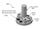
- FIG. 1 is an isometric view of a rotary valve embodiment of the invention.
- FIG. 2 is a view of an embodiment of the valve of the invention in the open position.
- FIG. 3 is a view of an embodiment of the valve of the invention in the closed position.
- FIG. 4 is side view of an embodiment of the valve of the invention depicting the fluid pressure maintaining the valve seat.
- a problem in the art capable of being solved by the embodiments of the present invention is creating a high pressure, wear resistant rotary valve. It has been surprisingly discovered that by using low-friction stators and rotors, a rotary valve can be constructed that is wear resistant, capable of sealing at high pressures, can open and close at high speeds, and is unaffected by abrasive fluids.
- FIG. 1 depicts an embodiment of a rotary valve 100 .
- Rotary valve 100 preferably comprises a drive shaft 105 , a rotor 110 and a stator 115 .
- drive shaft 105 , rotor 110 , and stator 115 are all made of the same corrosive resistant material, however each component can be of a different material, or combinations thereof.
- drive shaft 105 , rotor 110 , and stator 115 can be made of steel, carbon steel, steel alloys, bronze, brass, copper, titanium, aluminum, aluminum alloys, plastics, combinations thereof, or other materials.
- drive shaft 105 and rotor 110 are rotationally coupled and rotate at the same rate, while stator 115 remains stationary.
- drive shaft 105 and stator 115 can be rotationally coupled while rotor 110 remains stationary.
- Drive shaft 105 is preferably coupled to a rotational force generator.
- the rotational force generator can be, for example, an electric, gas, or steam motor, an inductor, a turbine (e.g. a fluid turbine powered by liquid or gas), a hand crank, or another method of imparting rotational force to rotor 110 .
- drive shaft 105 can rotate at speeds between 800 and 1200 rpm.
- rotor 110 extends, symmetrically from the center of drive shaft 105 .
- the arms of rotor 110 extend in diametrically opposed directions from the center of drive shaft 105 . While two arms are depicted in the figures, rotor 110 can have three, four, five, or another number of arms, or rotor 110 can be a disk or have another shape.
- Rotor 110 preferably has at least one solid bearing surface 120 coupled to each arm. As shown in the figures, each arm has two solid bearing surfaces 120 , however another number of bearing surfaces 120 can be used. Bearing surfaces 120 extend from rotor 110 toward stator 115 .
- each bearing surface 120 is a polycrystalline diamond compact (PDC).
- each bearing surface 120 can be aluminum oxide, silicon carbide, cubic boron nitride, or another erosion and abrasion resistant material.
- Each bearing surface 120 is preferably 2 inches in diameter and all of the bearing surfaces 120 are preferably identical.
- Stator 115 is preferably a disk with a plurality of bearing surfaces 125 projecting towards rotor 110 , however stator 115 can have another shape. Stator 115 is preferably coaxial with drive shaft 105 , however stator 115 can have a different axial arrangement. Preferably, stator 115 has a diameter equal to the inner diameter of a device into which valve 100 is placed. For example, if valve 100 is used in a drill string for down-hole drilling, the diameter of stator 115 would be equal to the inner diameter of the body of the drill string. Having the diameter of stator 115 equal to the inner diameter of the device into which valve 100 is placed, insures that all of the fluid passes through valve 100 .
- Stator 115 has two types of bearing surfaces 125 , ring bearing surfaces 125 a and solid bearing surfaces 125 b .
- both ring bearing surfaces 125 a and solid bearing surfaces 125 b are made of the same material.
- bearing surfaces 125 are made of PDC.
- other erosion and abrasion resistant materials can be used, for example aluminum oxide, silicon carbide, or cubic boron nitride.
- ring bearing surfaces 125 a are identical to sold bearing surfaces 125 b , however ring bearing surfaces 125 a have their centers bored out. For example, the centers can be bored out using an electrical discharge machine (EDM).
- EDM electrical discharge machine
- the holes (or nozzles) in the center of ring bearing surface 125 a can be 1 inch in diameter, 1.25 inches in diameter, or another diameter depending on the demands of the fluids passing through the valve.
- Ring bearing surface 125 a have the duel function of allowing fluid to pass through the valve and acting as a bearing surface between stator 115 and rotor 110 .
- the figures show stator 115 having four solid bearing surfaces 125 b and four ring bearing surfaces 125 a . Another number of solid and ring bearing surfaces can be used as long as there is at least one ring bearing surface 125 a .
- the ring bearing surface allows fluid to pass through valve 100 .
- each bearing surface 120 and bearing surface 125 is positioned at the same distance from the axis of rotation of the drive shaft 105 so that the bearing surfaces 120 pass over the bearing surfaces 125 when the rotor 110 rotates.
- there is an equal number of bearing surfaces 120 and ring bearing surfaces 125 a there can be more or less bearing surfaces 120 than ring bearing surfaces 125 a.
- valve 100 moves from an open position (shown in FIG. 2 ), through intermediary positions, to a closed position (shown in FIG. 3 ).
- a closed position shown in FIG. 3
- fluid is able to pass through ring bearing surfaces 125 a .
- bearing surfaces 120 create a seal with ring bearings surfaces 125 a and do not allow fluid to pass through valve 100 .
- two of the ring bearing surfaces 125 a are covered while two of the ring bearing surfaces 125 a are uncovered.
- the bearing surfaces can be arranged so that there is no rotational position where a portion of the ring bearing surfaces 125 a are uncovered. Additionally, the bearing surfaces can be arranged such that there is always at least one ring bearing surface 125 a that is uncovered. Additionally, bearing surfaces 120 can also be ring bearing surfaces such that the open position for valve 100 is when the ring bearing surfaces of rotor 110 and stator 115 align and the closed position for valve 100 is when the bearing surface of rotor 110 is aligned with the solid bearing surfaces of stator 115 .
- stator 110 is forced against stator 115 by the pressure of the fluid flowing through valve 100 (as shown in FIG. 4 ).
- the pressure of the fluid preferably maintains the valve seat, providing the necessary seals between bearing surface 120 and ring bearing surface 125 a .
- stator 100 is coupled to rotor 110 .
- stator 100 can be coupled to rotor 110 by a bolt, a bearing, friction, a cotter pin, or another fastener.
Landscapes
- Engineering & Computer Science (AREA)
- General Engineering & Computer Science (AREA)
- Mechanical Engineering (AREA)
- Physics & Mathematics (AREA)
- Fluid Mechanics (AREA)
- Life Sciences & Earth Sciences (AREA)
- Geology (AREA)
- Mining & Mineral Resources (AREA)
- Remote Sensing (AREA)
- Geophysics (AREA)
- Acoustics & Sound (AREA)
- Environmental & Geological Engineering (AREA)
- General Life Sciences & Earth Sciences (AREA)
- Geochemistry & Mineralogy (AREA)
- Multiple-Way Valves (AREA)
- Sliding Valves (AREA)
Abstract
A rotary valve is disclosed. The valve comprises a drive shaft, a rotor coupled to the drive shaft, a least one bearing surface coupled to the rotor, a stator adjacent to the rotor, at least one solid bearing surface coupled to the stator, and at least one ring bearing surface coupled to the stator.
Description
This application is a continuation of U.S. Non-Provisional application Ser. No. 14/680,148, filed Apr. 7, 2015, entitled “Valve Assembly,” which is a continuation of U.S. Non-Provisional application Ser. No. 13/940,487, filed Jul. 12, 2013, entitled “Valve Assembly,” which claims priority to U.S. Provisional Application No. 61/670,687, filed Jul. 12, 2012, entitled “Valve Assembly,” all of which are hereby specifically and entirely incorporated by reference.
1. Field of the Invention
The invention is directed to valves, specifically, the invention is directed to rotary valves.
2. Background of the Invention
Rotary valves are used in industry for a number of applications like controlling the flow of liquids to molds, regulating the flow of hydraulic fluids to control various machine functions, industrial process control, and controlling fluids which are directed against work pieces. The vast majority of these applications are conducted at low fluid pressures and at either low rotational speeds or through an indexed movement. These applications have been addressed through application of various known fluid regulation valve applications including gate valves, ball valves, butterfly valves, rotating shafts with various void designs and configurations, solenoid actuated valves of various designs, and valves designed with disks with multiple holes to redirect flow streams. These applications are generally acceptable for low speed, low pressure processes, but are not suitable for high speed, high pressure processes.
For example, solenoid valves are effective for regulating fluid flow up to a frequency of approximately 300 Hz at a pressure of up to 200 psi. These limitations are primarily due to the physical design of the solenoid which relies upon the reciprocating motion of magnetic contacts and is therefore subject to significant acceleration and deceleration forces, particularly at higher frequencies. These forces, the resulting jarring action, and the frictional heat generated make these type valves subject to failure at high frequencies of actuation.
Rotary valves employing multiple outlets have been used at frequencies up to 1000 Hz in applications where a low pressure differential between valve inlet and outlet ports is desired. These valves, however, are large and complex and necessarily have significant physical space requirements for the valve and for the appurtenant inlet and outlet piping.
Other types of valves have disadvantages that include: the valve actuation cycle speed (frequency) of the valve is too low, the valve is large and physically complex, the valve creates significant head loss, the valve cannot satisfactorily operate at high inlet pressures, or the valve cannot create the necessary frequency or amplitude of flow perturbation.
For the foregoing reasons, there is a need for a high-speed, high pressure rotary valve for controlling the flow of a fluid to produce high frequency fluid pulses or perturbations. Further, there is a need for such a valve which is relatively simple in design, compatible with standardized piping systems, and suitable for high pressure applications with minimal head loss through the valve.
The present invention overcomes the problems and disadvantages associated with current strategies and designs and provides new tools and methods creating rotary valves.
One embodiment of the invention is directed to a rotary valve. The valve comprises a drive shaft, a rotor coupled to the drive shaft, a least one bearing surface coupled to the rotor, a stator adjacent to the rotor, at least one solid bearing surface coupled to the stator and at least one ring bearing surface coupled to the stator.
Preferably, during rotation, the at least one bearing surface coupled to the rotor slides across the at least one solid bearing surface and the at least one ring bearing surface. In the preferred embodiment the at least one bearing surface coupled to the rotor, the at least one solid bearing surface, and the at least one ring bearing surface are positioned at an equal distance from a rotational axis of the drive shaft. Preferably the at least one ring bearing surface is adapted to allow fluid to flow therethrough. Preferably the at least one bearing surface coupled to the rotor, the at least one solid bearing surface, and the at least one ring bearing surface are polycrystalline diamond compacts.
In the preferred embodiment, the at least one bearing surface coupled to the rotor and the at least one ring bearing surface form a seal between themselves when aligned. Preferably, the drive shaft is powered by fluid flowing through the rotary valve. Preferably, there are an equal number of bearing surfaces coupled to the rotor and ring bearing surfaces. Preferably, the rotor comprises at least two arms and the at least two arms are rotationally balanced. In the preferred embodiment, fluid passing through the rotary valve forces the rotor into contact with the stator.
Other embodiments and advantages of the invention are set forth in part in the description, which follows, and in part, may be obvious from this description, or may be learned from the practice of the invention.
The invention is described in greater detail by way of example only and with reference to the attached drawing, in which:
As embodied and broadly described herein, the disclosures herein provide detailed embodiments of the invention. However, the disclosed embodiments are merely exemplary of the invention that may be embodied in various and alternative forms. Therefore, there is no intent that specific structural and functional details should be limiting, but rather the intention is that they provide a basis for the claims and as a representative basis for teaching one skilled in the art to variously employ the present invention
A problem in the art capable of being solved by the embodiments of the present invention is creating a high pressure, wear resistant rotary valve. It has been surprisingly discovered that by using low-friction stators and rotors, a rotary valve can be constructed that is wear resistant, capable of sealing at high pressures, can open and close at high speeds, and is unaffected by abrasive fluids.
In the preferred embodiment drive shaft 105 and rotor 110 are rotationally coupled and rotate at the same rate, while stator 115 remains stationary. However, drive shaft 105 and stator 115 can be rotationally coupled while rotor 110 remains stationary. Drive shaft 105 is preferably coupled to a rotational force generator. The rotational force generator can be, for example, an electric, gas, or steam motor, an inductor, a turbine (e.g. a fluid turbine powered by liquid or gas), a hand crank, or another method of imparting rotational force to rotor 110. In the preferred embodiment, drive shaft 105 can rotate at speeds between 800 and 1200 rpm.
Preferably, rotor 110 extends, symmetrically from the center of drive shaft 105. Preferably, to keep the system in balance during rotation, the arms of rotor 110 extend in diametrically opposed directions from the center of drive shaft 105. While two arms are depicted in the figures, rotor 110 can have three, four, five, or another number of arms, or rotor 110 can be a disk or have another shape. Rotor 110 preferably has at least one solid bearing surface 120 coupled to each arm. As shown in the figures, each arm has two solid bearing surfaces 120, however another number of bearing surfaces 120 can be used. Bearing surfaces 120 extend from rotor 110 toward stator 115. In the preferred embodiment each bearing surface 120 is a polycrystalline diamond compact (PDC). However, each bearing surface 120 can be aluminum oxide, silicon carbide, cubic boron nitride, or another erosion and abrasion resistant material. Each bearing surface 120 is preferably 2 inches in diameter and all of the bearing surfaces 120 are preferably identical.
In the preferred embodiment each bearing surface 120 and bearing surface 125 is positioned at the same distance from the axis of rotation of the drive shaft 105 so that the bearing surfaces 120 pass over the bearing surfaces 125 when the rotor 110 rotates. Preferably, there is an equal number of bearing surfaces 120 and ring bearing surfaces 125 a, however there can be more or less bearing surfaces 120 than ring bearing surfaces 125 a.
As drive shaft 105 and rotor 110 rotate, bearing surfaces 120 move across bearing surfaces 125. During rotation, valve 100 moves from an open position (shown in FIG. 2 ), through intermediary positions, to a closed position (shown in FIG. 3 ). Preferably, when valve 100 is in the open position, fluid is able to pass through ring bearing surfaces 125 a. When valve 100 is in the closed position, preferably bearing surfaces 120 create a seal with ring bearings surfaces 125 a and do not allow fluid to pass through valve 100. In the embodiment show in the figures, at certain rotational positions, two of the ring bearing surfaces 125 a are covered while two of the ring bearing surfaces 125 a are uncovered. However, in other embodiments, where it is undesirable to have a semi-open position, the bearing surfaces can be arranged so that there is no rotational position where a portion of the ring bearing surfaces 125 a are uncovered. Additionally, the bearing surfaces can be arranged such that there is always at least one ring bearing surface 125 a that is uncovered. Additionally, bearing surfaces 120 can also be ring bearing surfaces such that the open position for valve 100 is when the ring bearing surfaces of rotor 110 and stator 115 align and the closed position for valve 100 is when the bearing surface of rotor 110 is aligned with the solid bearing surfaces of stator 115.
In the preferred embodiment, rotor 110 is forced against stator 115 by the pressure of the fluid flowing through valve 100 (as shown in FIG. 4 ). The pressure of the fluid preferably maintains the valve seat, providing the necessary seals between bearing surface 120 and ring bearing surface 125 a. In other embodiments, stator 100 is coupled to rotor 110. For example, stator 100 can be coupled to rotor 110 by a bolt, a bearing, friction, a cotter pin, or another fastener.
Other embodiments and uses of the invention will be apparent to those skilled in the art from consideration of the specification and practice of the invention disclosed herein. All references cited herein, including all publications, U.S. and foreign patents and patent applications, are specifically and entirely incorporated by reference. It is intended that the specification and examples be considered exemplary only with the true scope and spirit of the invention indicated by the following claims. Furthermore, the term “comprising of” includes the terms “consisting of” and “consisting essentially of.”
Claims (11)
1. A rotary valve, comprising:
a drive shaft;
a rotor rotationally coupled to the drive shaft and having a rotor surface;
a stator adjacent to the rotor and having a stator surface, wherein the stator surface faces the rotor surface;
at least one solid bearing coupled to the stator and extending from the stator surface toward the rotor surface, each solid bearing having a solid bearing surface; and
at least one ring bearing coupled to the stator and extending from the stator surface toward the rotor surface, each ring bearing having a ring bearing surface;
wherein the rotor is adapted to cover one of the at least one solid bearing and at least one ring bearing while the other of the at least one solid bearing and at least one ring bearing remains uncovered.
2. The rotary valve of claim 1 , wherein, during rotation, the rotor surface slides across each solid bearing surface and each ring bearing surface.
3. The rotary valve of claim 1 , wherein the at least one solid bearing and the at least one ring bearing are positioned at an equal distance from a rotational axis of the drive shaft.
4. The rotary valve of claim 1 , wherein the at least one ring bearing is adapted to allow fluid to flow therethrough.
5. The rotary valve of claim 1 , wherein the at least one solid bearing and the at least one ring bearing are polycrystalline diamond compacts.
6. The rotary valve of claim 1 , wherein the rotor surface and each ring bearing surface form a seal between themselves when aligned.
7. The rotary valve of claim 1 , wherein the drive shaft is powered by fluid flowing through the rotary valve.
8. The rotary valve of claim 1 , wherein the rotor comprises at least two arms and the at least two arms are rotationally balanced.
9. The rotary valve of claim 1 , wherein fluid passing through the rotary valve forces the rotor into contact with the stator.
10. The rotary valve of claim 1 , wherein a bore in the ring bearing is parallel to the drive shaft.
11. The rotary valve of claim 1 , wherein the rotor and stator are coaxial.
Priority Applications (1)
| Application Number | Priority Date | Filing Date | Title |
|---|---|---|---|
| US15/230,629 US10161530B2 (en) | 2012-07-12 | 2016-08-08 | Valve assembly |
Applications Claiming Priority (4)
| Application Number | Priority Date | Filing Date | Title |
|---|---|---|---|
| US201261670687P | 2012-07-12 | 2012-07-12 | |
| US13/940,487 US9010370B2 (en) | 2012-07-12 | 2013-07-12 | Valve assembly |
| US14/680,148 US9410637B2 (en) | 2012-07-12 | 2015-04-07 | Valve assembly |
| US15/230,629 US10161530B2 (en) | 2012-07-12 | 2016-08-08 | Valve assembly |
Related Parent Applications (1)
| Application Number | Title | Priority Date | Filing Date |
|---|---|---|---|
| US14/680,148 Continuation US9410637B2 (en) | 2012-07-12 | 2015-04-07 | Valve assembly |
Publications (2)
| Publication Number | Publication Date |
|---|---|
| US20160356387A1 US20160356387A1 (en) | 2016-12-08 |
| US10161530B2 true US10161530B2 (en) | 2018-12-25 |
Family
ID=49913169
Family Applications (3)
| Application Number | Title | Priority Date | Filing Date |
|---|---|---|---|
| US13/940,487 Active US9010370B2 (en) | 2012-07-12 | 2013-07-12 | Valve assembly |
| US14/680,148 Active US9410637B2 (en) | 2012-07-12 | 2015-04-07 | Valve assembly |
| US15/230,629 Active US10161530B2 (en) | 2012-07-12 | 2016-08-08 | Valve assembly |
Family Applications Before (2)
| Application Number | Title | Priority Date | Filing Date |
|---|---|---|---|
| US13/940,487 Active US9010370B2 (en) | 2012-07-12 | 2013-07-12 | Valve assembly |
| US14/680,148 Active US9410637B2 (en) | 2012-07-12 | 2015-04-07 | Valve assembly |
Country Status (2)
| Country | Link |
|---|---|
| US (3) | US9010370B2 (en) |
| WO (1) | WO2014011960A2 (en) |
Families Citing this family (13)
| Publication number | Priority date | Publication date | Assignee | Title |
|---|---|---|---|---|
| EP3279530A4 (en) * | 2015-04-02 | 2019-09-11 | Science & Technology Development Fund | Direct-operated hydraulic servo valves |
| CN105134988B (en) * | 2015-08-04 | 2019-02-15 | 安徽春辉仪表线缆集团有限公司 | A kind of shut-off valve carrying out flow adjusting |
| US9914190B2 (en) * | 2016-06-07 | 2018-03-13 | Robert G. Hartness | Blast gate for vacuum system |
| BR112019004918A2 (en) | 2016-10-19 | 2019-06-04 | Halliburton Energy Services Inc | rotary valve, and method for directing a drill bit. |
| WO2018236516A1 (en) * | 2017-06-23 | 2018-12-27 | Halliburton Energy Services, Inc. | Fallback prevention valve apparatus, system and method |
| CN107795317B (en) * | 2017-10-24 | 2020-11-10 | 中国石油大学(华东) | Rotary valve rotating speed control method of measurement while drilling tool |
| CN110410534B (en) * | 2019-08-16 | 2024-02-20 | 凯铭科技(杭州)有限公司 | Multi-channel flow control valve |
| CN111156556B (en) * | 2020-01-17 | 2021-10-08 | 宁波方太厨具有限公司 | Filter device and range hood with same |
| CN112377643B (en) * | 2020-10-29 | 2025-06-27 | 厦门市欧立通电子科技开发有限公司 | Manual and induction integrated faucet |
| US11953104B2 (en) * | 2021-01-29 | 2024-04-09 | Pathway Industries, Inc. | Rotary multi-way distributor with plural port tracks |
| CN113431927A (en) * | 2021-07-09 | 2021-09-24 | 姜林 | Rotary butterfly type three-way pressure reducing valve |
| DE102022004226A1 (en) * | 2022-11-15 | 2024-05-16 | AMR Hydraulik Zwickau GmbH | Valve system |
| CN116733995A (en) * | 2023-05-31 | 2023-09-12 | 辽宁五寰特种材料与智能装备产业技术研究院有限公司 | Totally-enclosed electric drive gate valve |
Citations (24)
| Publication number | Priority date | Publication date | Assignee | Title |
|---|---|---|---|---|
| US2519574A (en) * | 1944-02-28 | 1950-08-22 | James W F Holl | Rotary fluid valve |
| US2653003A (en) * | 1946-10-26 | 1953-09-22 | John W Overbeke | Control valve |
| US2832561A (en) * | 1953-05-04 | 1958-04-29 | James W F Holl | Rotary valve with seal seat |
| US2925095A (en) * | 1954-11-23 | 1960-02-16 | Alfred O Bates | Valve |
| US2961003A (en) * | 1956-04-24 | 1960-11-22 | Shafer Valve Co | Single-acting piston pump and valve unit |
| US2990853A (en) * | 1958-01-23 | 1961-07-04 | Nat Tank Co | Rotary valve |
| US4574840A (en) * | 1984-12-28 | 1986-03-11 | Uop Inc. | Multiport axial valve with balanced rotor |
| US4595034A (en) * | 1984-07-05 | 1986-06-17 | Hutson Roy C | Three-position, four-way, short-stroke rotary valve |
| US4674538A (en) * | 1985-12-18 | 1987-06-23 | Johnson Yes | Device for regulating water flow in a water filter |
| US4921015A (en) * | 1989-07-21 | 1990-05-01 | John Crane, Inc. | Rotary vacuum valve |
| US5188151A (en) * | 1991-10-22 | 1993-02-23 | Cold Jet, Inc. | Flow diverter valve |
| US5307838A (en) * | 1992-01-08 | 1994-05-03 | Societe Nationale D'etude Et De Construction De Moteurs D'aviation (S.N.E.C.M.A) | Rotary valve assembly |
| US5372351A (en) | 1992-06-03 | 1994-12-13 | Nova Scotia Research Foundation Corporation | Manual override system for rotary magnetically operated valve |
| US5704396A (en) * | 1996-01-05 | 1998-01-06 | Westinghouse Air Brake Company | Modulation rotary valve |
| US5862833A (en) * | 1995-11-22 | 1999-01-26 | Mike Kenney Tool, Inc. | Distribution valve for high pressure coolant used in a metalworking machine application |
| US6234207B1 (en) * | 1998-06-23 | 2001-05-22 | Fuji Injector Corporation | Device for changing flow of operating medium in air conditioning system |
| US6257279B1 (en) | 1997-07-07 | 2001-07-10 | Ge-Harris Railway Electronics, L.L.C. | Plural function fluid valve and method |
| US20020148509A1 (en) * | 2001-04-12 | 2002-10-17 | Tine Theodore J. | Fuel valves |
| US6607371B1 (en) | 1996-09-16 | 2003-08-19 | Charles D. Raymond | Pneudraulic rotary pump and motor |
| US20050056149A1 (en) * | 2003-09-17 | 2005-03-17 | Metso Automation Usa Inc. | System and method for treating fluid using a multi-port valve assembly |
| US6973974B2 (en) | 1999-09-24 | 2005-12-13 | Schlumberger Technology Corporation | Valves for use in wells |
| US20070028971A1 (en) * | 2005-08-05 | 2007-02-08 | Wagner Glenn P | Rotary valve with internal leak control system |
| US7793940B2 (en) * | 2006-05-16 | 2010-09-14 | Skf Usa Inc. | Mechanical end face seal with ultrahard face material |
| US20110247359A1 (en) * | 2008-09-05 | 2011-10-13 | Danfoss A/S | Expansion valve with force equalization |
Family Cites Families (1)
| Publication number | Priority date | Publication date | Assignee | Title |
|---|---|---|---|---|
| NL126881C (en) * | 1959-06-04 | 1900-01-01 |
-
2013
- 2013-07-12 WO PCT/US2013/050209 patent/WO2014011960A2/en not_active Ceased
- 2013-07-12 US US13/940,487 patent/US9010370B2/en active Active
-
2015
- 2015-04-07 US US14/680,148 patent/US9410637B2/en active Active
-
2016
- 2016-08-08 US US15/230,629 patent/US10161530B2/en active Active
Patent Citations (24)
| Publication number | Priority date | Publication date | Assignee | Title |
|---|---|---|---|---|
| US2519574A (en) * | 1944-02-28 | 1950-08-22 | James W F Holl | Rotary fluid valve |
| US2653003A (en) * | 1946-10-26 | 1953-09-22 | John W Overbeke | Control valve |
| US2832561A (en) * | 1953-05-04 | 1958-04-29 | James W F Holl | Rotary valve with seal seat |
| US2925095A (en) * | 1954-11-23 | 1960-02-16 | Alfred O Bates | Valve |
| US2961003A (en) * | 1956-04-24 | 1960-11-22 | Shafer Valve Co | Single-acting piston pump and valve unit |
| US2990853A (en) * | 1958-01-23 | 1961-07-04 | Nat Tank Co | Rotary valve |
| US4595034A (en) * | 1984-07-05 | 1986-06-17 | Hutson Roy C | Three-position, four-way, short-stroke rotary valve |
| US4574840A (en) * | 1984-12-28 | 1986-03-11 | Uop Inc. | Multiport axial valve with balanced rotor |
| US4674538A (en) * | 1985-12-18 | 1987-06-23 | Johnson Yes | Device for regulating water flow in a water filter |
| US4921015A (en) * | 1989-07-21 | 1990-05-01 | John Crane, Inc. | Rotary vacuum valve |
| US5188151A (en) * | 1991-10-22 | 1993-02-23 | Cold Jet, Inc. | Flow diverter valve |
| US5307838A (en) * | 1992-01-08 | 1994-05-03 | Societe Nationale D'etude Et De Construction De Moteurs D'aviation (S.N.E.C.M.A) | Rotary valve assembly |
| US5372351A (en) | 1992-06-03 | 1994-12-13 | Nova Scotia Research Foundation Corporation | Manual override system for rotary magnetically operated valve |
| US5862833A (en) * | 1995-11-22 | 1999-01-26 | Mike Kenney Tool, Inc. | Distribution valve for high pressure coolant used in a metalworking machine application |
| US5704396A (en) * | 1996-01-05 | 1998-01-06 | Westinghouse Air Brake Company | Modulation rotary valve |
| US6607371B1 (en) | 1996-09-16 | 2003-08-19 | Charles D. Raymond | Pneudraulic rotary pump and motor |
| US6257279B1 (en) | 1997-07-07 | 2001-07-10 | Ge-Harris Railway Electronics, L.L.C. | Plural function fluid valve and method |
| US6234207B1 (en) * | 1998-06-23 | 2001-05-22 | Fuji Injector Corporation | Device for changing flow of operating medium in air conditioning system |
| US6973974B2 (en) | 1999-09-24 | 2005-12-13 | Schlumberger Technology Corporation | Valves for use in wells |
| US20020148509A1 (en) * | 2001-04-12 | 2002-10-17 | Tine Theodore J. | Fuel valves |
| US20050056149A1 (en) * | 2003-09-17 | 2005-03-17 | Metso Automation Usa Inc. | System and method for treating fluid using a multi-port valve assembly |
| US20070028971A1 (en) * | 2005-08-05 | 2007-02-08 | Wagner Glenn P | Rotary valve with internal leak control system |
| US7793940B2 (en) * | 2006-05-16 | 2010-09-14 | Skf Usa Inc. | Mechanical end face seal with ultrahard face material |
| US20110247359A1 (en) * | 2008-09-05 | 2011-10-13 | Danfoss A/S | Expansion valve with force equalization |
Non-Patent Citations (1)
| Title |
|---|
| PCT Patentability Report for PCT/US13/050205, dated Dec. 23, 2013. |
Also Published As
| Publication number | Publication date |
|---|---|
| US20150211653A1 (en) | 2015-07-30 |
| US9010370B2 (en) | 2015-04-21 |
| US20160356387A1 (en) | 2016-12-08 |
| WO2014011960A3 (en) | 2014-03-06 |
| US9410637B2 (en) | 2016-08-09 |
| US20140014866A1 (en) | 2014-01-16 |
| WO2014011960A2 (en) | 2014-01-16 |
Similar Documents
| Publication | Publication Date | Title |
|---|---|---|
| US10161530B2 (en) | Valve assembly | |
| JP2879441B2 (en) | Idler disk | |
| CN109790943B (en) | Ball valve system | |
| GB2548063B (en) | Choke valve trim | |
| US9915117B2 (en) | Fluid pulse valve | |
| CN110410387A (en) | Gas pulses device | |
| CA2578869C (en) | Rotating check valve for compression equipment | |
| CN201487237U (en) | Pilot operated stop valve | |
| US20180030813A1 (en) | Fluid Pulse Valve | |
| CN104653800A (en) | Novel abrasive disk valve | |
| WO2020247350A1 (en) | Floating valve seat for a rotary control valve for use in severe service applications | |
| CN204459216U (en) | High-pressure self-balance self-sealing piston formula regulates throttling stop valve | |
| US20170362916A1 (en) | Fluid pulse valve | |
| CN213271089U (en) | Novel wear-resistant round rotary valve | |
| CN212509628U (en) | High-performance adjusting ball valve | |
| CN201651349U (en) | Butterfly valve with fully-bushed valve rod | |
| US11815191B2 (en) | Adjustable erosion resistant choke valve | |
| CN215214882U (en) | Three-way four-sealing ball valve | |
| CN202348682U (en) | Slow-rotary-speed corrosion-resisting wear-resisting centrifugal pump | |
| CN202040349U (en) | Valve shaft bushing structure of soft seal butterfly valve | |
| CN217080940U (en) | Rotary fluid high-frequency multi-channel opening and closing valve | |
| CN210566886U (en) | Two-phase flow sealing rotary seat | |
| US5549275A (en) | Valve with adjustably pressurized sealing gaskets | |
| CN120991086A (en) | A full-bore metal-sealed rotary ball valve for water supply and drainage | |
| JP4831975B2 (en) | Small centrifugal pump and operation method of small centrifugal pump |
Legal Events
| Date | Code | Title | Description |
|---|---|---|---|
| STCF | Information on status: patent grant |
Free format text: PATENTED CASE |
|
| MAFP | Maintenance fee payment |
Free format text: PAYMENT OF MAINTENANCE FEE, 4TH YR, SMALL ENTITY (ORIGINAL EVENT CODE: M2551); ENTITY STATUS OF PATENT OWNER: SMALL ENTITY Year of fee payment: 4 |
|
| AS | Assignment |
Owner name: PNC BANK, NATIONAL ASSOCIATION, PENNSYLVANIA Free format text: SECURITY INTEREST;ASSIGNORS:SUPERIOR DRILLING PRODUCTS, LLC (F/K/A DTI MERGER SUB II, LLC);EXTREME TECHNOLOGIES LLC;HARD ROCK SOLUTIONS, LLC;REEL/FRAME:068804/0366 Effective date: 20241004 |