US10151672B2 - Device and a method for managing a sample to be analyzed and a solid sample carrier and liquid sample carrier - Google Patents
Device and a method for managing a sample to be analyzed and a solid sample carrier and liquid sample carrier Download PDFInfo
- Publication number
- US10151672B2 US10151672B2 US15/117,519 US201515117519A US10151672B2 US 10151672 B2 US10151672 B2 US 10151672B2 US 201515117519 A US201515117519 A US 201515117519A US 10151672 B2 US10151672 B2 US 10151672B2
- Authority
- US
- United States
- Prior art keywords
- sample
- sample well
- magnetic field
- well
- liquid
- Prior art date
- Legal status (The legal status is an assumption and is not a legal conclusion. Google has not performed a legal analysis and makes no representation as to the accuracy of the status listed.)
- Active, expires
Links
Images


Classifications
-
- G—PHYSICS
- G01—MEASURING; TESTING
- G01N—INVESTIGATING OR ANALYSING MATERIALS BY DETERMINING THEIR CHEMICAL OR PHYSICAL PROPERTIES
- G01N1/00—Sampling; Preparing specimens for investigation
- G01N1/28—Preparing specimens for investigation including physical details of (bio-)chemical methods covered elsewhere, e.g. G01N33/50, C12Q
- G01N1/286—Preparing specimens for investigation including physical details of (bio-)chemical methods covered elsewhere, e.g. G01N33/50, C12Q involving mechanical work, e.g. chopping, disintegrating, compacting, homogenising
-
- B—PERFORMING OPERATIONS; TRANSPORTING
- B01—PHYSICAL OR CHEMICAL PROCESSES OR APPARATUS IN GENERAL
- B01L—CHEMICAL OR PHYSICAL LABORATORY APPARATUS FOR GENERAL USE
- B01L3/00—Containers or dishes for laboratory use, e.g. laboratory glassware; Droppers
- B01L3/50—Containers for the purpose of retaining a material to be analysed, e.g. test tubes
- B01L3/508—Containers for the purpose of retaining a material to be analysed, e.g. test tubes rigid containers not provided for above
-
- G—PHYSICS
- G01—MEASURING; TESTING
- G01N—INVESTIGATING OR ANALYSING MATERIALS BY DETERMINING THEIR CHEMICAL OR PHYSICAL PROPERTIES
- G01N21/00—Investigating or analysing materials by the use of optical means, i.e. using sub-millimetre waves, infrared, visible or ultraviolet light
- G01N21/01—Arrangements or apparatus for facilitating the optical investigation
- G01N21/03—Cuvette constructions
-
- G—PHYSICS
- G01—MEASURING; TESTING
- G01N—INVESTIGATING OR ANALYSING MATERIALS BY DETERMINING THEIR CHEMICAL OR PHYSICAL PROPERTIES
- G01N21/00—Investigating or analysing materials by the use of optical means, i.e. using sub-millimetre waves, infrared, visible or ultraviolet light
- G01N21/62—Systems in which the material investigated is excited whereby it emits light or causes a change in wavelength of the incident light
- G01N21/63—Systems in which the material investigated is excited whereby it emits light or causes a change in wavelength of the incident light optically excited
-
- G—PHYSICS
- G01—MEASURING; TESTING
- G01N—INVESTIGATING OR ANALYSING MATERIALS BY DETERMINING THEIR CHEMICAL OR PHYSICAL PROPERTIES
- G01N35/00—Automatic analysis not limited to methods or materials provided for in any single one of groups G01N1/00 - G01N33/00; Handling materials therefor
- G01N35/0098—Automatic analysis not limited to methods or materials provided for in any single one of groups G01N1/00 - G01N33/00; Handling materials therefor involving analyte bound to insoluble magnetic carrier, e.g. using magnetic separation
-
- G—PHYSICS
- G01—MEASURING; TESTING
- G01N—INVESTIGATING OR ANALYSING MATERIALS BY DETERMINING THEIR CHEMICAL OR PHYSICAL PROPERTIES
- G01N35/00—Automatic analysis not limited to methods or materials provided for in any single one of groups G01N1/00 - G01N33/00; Handling materials therefor
- G01N35/10—Devices for transferring samples or any liquids to, in, or from, the analysis apparatus, e.g. suction devices, injection devices
- G01N35/1009—Characterised by arrangements for controlling the aspiration or dispense of liquids
-
- G—PHYSICS
- G01—MEASURING; TESTING
- G01R—MEASURING ELECTRIC VARIABLES; MEASURING MAGNETIC VARIABLES
- G01R33/00—Arrangements or instruments for measuring magnetic variables
- G01R33/02—Measuring direction or magnitude of magnetic fields or magnetic flux
-
- B—PERFORMING OPERATIONS; TRANSPORTING
- B01—PHYSICAL OR CHEMICAL PROCESSES OR APPARATUS IN GENERAL
- B01L—CHEMICAL OR PHYSICAL LABORATORY APPARATUS FOR GENERAL USE
- B01L2300/00—Additional constructional details
- B01L2300/08—Geometry, shape and general structure
- B01L2300/0887—Laminated structure
-
- B—PERFORMING OPERATIONS; TRANSPORTING
- B01—PHYSICAL OR CHEMICAL PROCESSES OR APPARATUS IN GENERAL
- B01L—CHEMICAL OR PHYSICAL LABORATORY APPARATUS FOR GENERAL USE
- B01L2300/00—Additional constructional details
- B01L2300/12—Specific details about materials
-
- B—PERFORMING OPERATIONS; TRANSPORTING
- B01—PHYSICAL OR CHEMICAL PROCESSES OR APPARATUS IN GENERAL
- B01L—CHEMICAL OR PHYSICAL LABORATORY APPARATUS FOR GENERAL USE
- B01L2300/00—Additional constructional details
- B01L2300/12—Specific details about materials
- B01L2300/126—Paper
-
- G—PHYSICS
- G01—MEASURING; TESTING
- G01N—INVESTIGATING OR ANALYSING MATERIALS BY DETERMINING THEIR CHEMICAL OR PHYSICAL PROPERTIES
- G01N1/00—Sampling; Preparing specimens for investigation
- G01N1/28—Preparing specimens for investigation including physical details of (bio-)chemical methods covered elsewhere, e.g. G01N33/50, C12Q
- G01N1/286—Preparing specimens for investigation including physical details of (bio-)chemical methods covered elsewhere, e.g. G01N33/50, C12Q involving mechanical work, e.g. chopping, disintegrating, compacting, homogenising
- G01N2001/2873—Cutting or cleaving
- G01N2001/288—Filter punches
Definitions
- the invention relates to a method and a device for managing a sample to be examined.
- the device can be, for example but not necessarily, an instrument for dispensing samples to sample wells or an optical measurement instrument.
- the invention is related to a solid sample carrier suitable for collecting samples of biological material to be analyzed.
- the invention is related to liquid sample carrier suitable for carrying biological material to be analyzed.
- One conventional practice is to impregnate one or more drops of fluid samples to be analyzed onto a solid sample carrier, dry the solid sample carrier impregnated with the fluid, and then send the solid sample carrier to a laboratory for analysis.
- the fluid to be analyzed can be, for example, blood of a newborn baby and the solid sample carrier can be, for example, a sheet of paper or some other suitable material which is able to carry the fluid to be analyzed.
- the laboratory one or more pieces containing the dried fluid to be analyzed are cut off from the solid sample carrier and the one or more pieces that have been cut off are conveyed, for further analysis, to one or more sample wells of e.g. a microtitration plate or some other sample well element.
- Each piece can be cut off from the solid sample carrier for example with a punch and a die provided with a channel for the punch, where the punch is arranged to cut off the piece with a single stroke through the solid sample carrier. It is also possible to use a cutting instrument capable of producing a localized, point-form cut on the solid sample carrier and to move the point-form cutting impact produced by the cutting instrument along the outer periphery of each piece so as to detach the piece from the solid sample carrier. Another conventional practice is to handle the sample to be analyzed in liquid form so that the sample is blended or dissolved in liquid sample carrier. In this case, one or more drops of the liquid sample carrier containing the sample are dispensed to one or more sample wells for further analysis.
- solid means that material under consideration is in none of the following phases: gas, plasma, and liquid.
- solid does not exclude porousness and other kind of ability to be impregnated with liquid. Therefore, in the context of this document, solid material can be porous or otherwise capable of being impregnated with liquid. Furthermore, the term “solid” does not exclude plasticity, elasticity, and flexibility of material under consideration. Yet furthermore, the term “solid” does not exclude mosaic structure of an object under consideration.
- solid sample carrier means a carrier made of solid material, e.g. a sheet of paper, capable of carrying sample material and the term “liquid sample carrier” means carrier liquid i.e. liquid capable of carrying sample material.
- the device according to the invention comprises:
- the movement of the sample to the sample well and/or the position of the sample in the sample well can be monitored and/or changed.
- the verb “to manage” is to be understood in a broad sense so that it may mean, inter alia, mere checking actions for monitoring purposes, or control actions influencing an object under consideration, or both.
- the device can be, for example but not necessarily, an instrument for dispensing samples to sample wells or an optical measurement instrument.
- the method according to the invention comprises:
- the solid sample carrier comprises:
- the body of the solid sample carrier can be, for example, a sheet of paper or some other suitable material which is able to carry the biological material to be analyzed.
- liquid sample carrier suitable for carrying biological material to be analyzed.
- the liquid sample carrier according to the invention is a colloid with dispersed phase particles comprising magnetically amplifying material having relative magnetic permeability constant greater than one.
- the particles are ferro- or paramagnetic and their sizes can be, for example, on micro- or nanometer-class.
- the particles can be, for example, poly-vinyl-alcohol “PVA” particles which contain magnetite.
- the diameter of the PVA particles can be, for example, about 1-2 ⁇ m.
- FIG. 1 shows a schematic side view of a device according to an exemplifying embodiment of the invention
- FIG. 2 a shows a schematic side view of a device according to another exemplifying embodiment of the invention
- FIG. 2 b shows a solid sample carrier according to an exemplifying embodiment of the invention
- FIG. 3 shows a schematic side view of a device according to an exemplifying embodiment of the invention
- FIG. 4 shows a schematic side view of a device according to an exemplifying embodiment of the invention
- FIG. 5 shows a schematic side view of a device according to an exemplifying embodiment of the invention.
- FIG. 6 shows a flow chart of a method according to an exemplifying embodiment of the invention for managing a sample to be analyzed.
- FIG. 1 shows a schematic side view of a device according to an exemplifying embodiment of the invention.
- the device is an instrument for dispensing samples to sample wells.
- the device comprises a support element 101 for supporting a sample well element 112 , e.g. a microtitration plate, comprising one or more sample wells.
- the sample well element 112 is presented as a section view.
- the device comprises a dispensing element 103 for dispensing a sample, and the support element 101 is configured to support the sample well element 112 so that an appropriate sample well is able to receive the sample from the dispensing element 103 .
- FIG. 1 shows a schematic side view of a device according to an exemplifying embodiment of the invention.
- the device is an instrument for dispensing samples to sample wells.
- the device comprises a support element 101 for supporting a sample well element 112 , e.g. a microtitration plate, comprising one or more sample wells.
- the dispensing element 103 comprises a pipette for dispensing liquid sample carrier.
- the dispensed quantity 120 of the liquid sample carrier contains the sample to be analyzed.
- the liquid sample carrier is a colloid with dispersed phase particles comprising magnetically amplifying material that has relative magnetic permeability constant greater than one, i.e. ⁇ r >1.
- the particles can be, for example, polyvinyl-alcohol “PVA” particles containing magnetite.
- the PVA particles containing magnetite are colloidally stable and chemically inert.
- the dispensed quantity 120 of the liquid sample carrier containing the sample to be analyzed is presented as a drop.
- the device comprises magnetizing equipment 102 for producing magnetic field 130 capable of interacting with the magnetically amplifying material attached to the sample.
- the device further comprises a sensor 106 for detecting the change in the magnetic field so as to monitor whether the sample is correctly moved to the sample well.
- the magnetizing equipment 102 is a piece of permanent magnet material but it is also possible that the magnetizing equipment comprises a coil connected to a source of electrical current.
- the sensor 106 comprises a coil for producing a signal indicative of changes in the magnetic field and a processor 113 for processing the signal into a form suitable for further use.
- FIG. 2 a shows a schematic side view of a device according to an exemplifying embodiment of the invention.
- the device is an instrument for dispensing samples to sample wells.
- the device comprises a support element 201 for supporting a sample well element 212 comprising sample wells.
- the sample well element 212 is presented as a section view. It is to be noted that the sample well element 212 is not necessarily an integral part of the device because the sample well element is a replaceable component and devices of the kind described here can be delivered to laboratories etc. without sample well elements and the sample well elements can be delivered by different vendors.
- the device comprises a dispensing element 203 for dispensing a sample
- the support element 201 is configured to support the sample well element 212 so that an appropriate sample well is able to receive the sample from the dispensing element 203 .
- the dispensing element 203 comprises a cutting element for cutting off a piece from a solid sample carrier 210 that is a solid sample carrier according to an exemplifying embodiment of the invention.
- the solid sample carrier 210 is suitable for collecting samples of material to be analyzed, e.g. blood of a newborn baby.
- the cutting element comprises a punch 204 and a die 205 provided with a channel for the punch.
- the punch is arranged to cut off the piece from the solid sample carrier 210 with a stroke through the solid sample carrier.
- the cutting element comprises a cutting instrument for producing a point-form cut on the solid sample carrier and equipment for directing the cutting instrument so that cutting impact produced by the cutting instrument is moved along the outer periphery of the piece so as to cut off the piece.
- the above-mentioned cutting instrument can be, for example, a laser beam cutter or a liquid, e.g. water, jet cutter.
- FIG. 2 b illustrates the solid sample carrier 210 by showing a view seen along the arrow B presented in FIG. 2 a .
- the solid sample carrier comprises a body 211 capable of carrying the sample material to be analyzed.
- the body can be, for example, a sheet of paper or some other suitable, and preferably porous, material which is able to carry the sample material to be analyzed.
- Blotches 221 , 222 , 223 and 224 shown in FIG. 2 b , on the solid sample carrier 210 are the regions of the solid sample carrier into which the sample material has been impregnated. Pieces are cut off from the regions of the solid sample carrier into which the sample material has been impregnated. For example, the piece 220 shown in FIG.
- the solid sample carrier 210 may comprise a machine-readable identifier 226 that may contain, for example, information about the donor of the sample material, information about the time and place of taking the sample, and/or other appropriate information.
- the solid sample carrier 210 comprises magnetically amplifying material combined with the body 211 .
- the body 211 is a sheet of paper that comprises magnetically amplifying particles, e.g. iron, magnetite, or ferrite particles, among fibers of the paper.
- the paper can be provided with the magnetically amplifying particles, for example, during manufacture of the paper.
- a solid sample carrier according to another exemplifying embodiment of the invention comprises, on the reverse surface of the body 211 , a layer containing magnetically amplifying material.
- the layer can be, for example, a layer of magnetically amplifying paint or a layer of magnetically amplifying particles functionalized with e.g. isocyanate that is able to combine with cellulose covalently.
- a solid sample carrier according to an exemplifying embodiment of the invention comprises a layer of plastic between the body and the layer containing the magnetically amplifying material.
- the device illustrated in FIG. 2 a comprises magnetizing equipment 202 for producing magnetic field capable of interacting with the magnetically amplifying material attached to the piece 220 .
- the magnetically amplifying material attached to the piece causes a change in the magnetic field.
- the device further comprises a sensor 206 for detecting the change in the magnetic field so as to monitor whether the piece 220 is correctly moved to the sample well.
- the sensor 206 comprises a coil for producing a signal indicative of changes in the magnetic field and a processor 213 for processing the signal into a form suitable for further use.
- FIG. 3 shows a schematic side view of a device according to an exemplifying embodiment of the invention.
- the device comprises a support element 301 for supporting a sample well element 312 comprising sample wells.
- the sample well element 312 is presented as a section view.
- each sample well contains a piece that has been cut off from a solid sample carrier and that has been impregnated with sample material to be analyzed, e.g. blood.
- the piece contains magnetically amplifying material.
- the device is configured to add, to each sample well, liquid which dissolves the sample material or certain components of the sample material from the piece.
- the device comprises a liquid dispenser 307 for adding the liquid to each sample well.
- the device comprises magnetizing equipment 302 arranged to produce magnetic field on the vicinity of the bottom of an appropriate sample well so that the magnetic field is capable of drawing the piece to the bottom of the sample well when the liquid is added to the sample well.
- magnetizing equipment 302 arranged to produce magnetic field on the vicinity of the bottom of an appropriate sample well so that the magnetic field is capable of drawing the piece to the bottom of the sample well when the liquid is added to the sample well.
- FIG. 4 shows a schematic side view of a device according to an exemplifying embodiment of the invention.
- the device is an optical measurement instrument.
- the device comprises a support element 401 for supporting a sample well element 412 , e.g. a microtitration plate, comprising sample wells.
- the sample well element 412 is presented as a section view.
- each sample well contains a piece that has been cut off from a solid sample carrier and that has been impregnated with sample material to be analyzed, e.g. blood. Furthermore, the piece contains magnetically amplifying material.
- each sample well contains liquid which has dissolved the sample material or certain components of the sample material from the piece.
- the device further comprises a light source 408 for directing excitation light to the liquid contained by a sample well and a detector 409 for measuring light emitted by the liquid contained by the sample well.
- the device comprises magnetizing equipment 402 arranged to produce magnetic field on the vicinity of the bottom of the sample well so that the magnetic field is capable of drawing the piece to the bottom of the sample well when the light emitted by the liquid contained by the sample well is measured. Thus, it can be ensured that the piece does not disturb the optical measurement.
- FIG. 5 shows a schematic side view of a device according to an exemplifying embodiment of the invention.
- the device is an optical measurement instrument.
- the device comprises a support element 501 for supporting a sample well element 512 , e.g. a microtitration plate, comprising sample wells.
- the sample well element 512 is presented as a section view.
- each sample well contains a piece that has been cut off from a solid sample carrier and that has been impregnated with sample material to be analyzed.
- the piece contains magnetically amplifying material.
- each sample well contains liquid which has dissolved the sample material or certain components of the sample material from the piece.
- the device further comprises a light source 508 for directing light to the liquid contained by a sample well and a detector 509 for measuring light generated by the light source and penetrated the liquid contained by the sample well.
- the sample well element 512 is assumed to be made of material that is sufficiently transparent for the light generated by the light source 508 .
- the device comprises magnetizing equipment 502 arranged to produce magnetic field on the vicinity of a side wall of the sample well so that the magnetic field is capable of drawing the piece to the side wall of the sample well when the light penetrating the liquid contained by the sample well is measured. Thus, it can be ensured that the piece does not disturb the optical measurement.
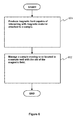
- FIG. 6 shows a flow chart of a method according to an exemplifying embodiment of the invention for managing a sample to be analyzed.
- the method comprises the following actions:
- a method according to an exemplifying embodiment of the invention comprises dispensing the sample, and subsequently, the sample is conveyed to the sample well.
- the magnetic field is directed to a route of the sample to the sample well, and a change caused in the magnetic field by the magnetically amplifying material attached to the sample moving to the sample well is detected so as to monitor whether the sample is correctly moved to the sample well.
- the dispensing the sample comprises pipetting liquid sample carrier which is a colloid with dispersed phase particles comprising magnetically amplifying material.
- the dispensed quantity of the liquid sample carrier contains the sample to be analyzed.
- the above-mentioned particles can be, for example, poly-vinyl-alcohol “PVA” particles containing magnetite.
- the dispensing the sample comprises cutting off a piece from a solid sample carrier containing magnetically amplifying material.
- the piece carries the sample to be analyzed.
- a method according to an exemplifying embodiment of the invention comprises adding liquid to the sample well and producing magnetic field on the vicinity of the bottom of the sample well so that the magnetic field draws a piece detached from a solid sample carrier containing magnetically amplifying material to the bottom of the sample well when the liquid is added to the sample well.
- a method comprises directing excitation light to liquid contained by the sample well, measuring light emitted by the liquid contained by the sample well, and producing magnetic field on the vicinity of the bottom of the sample well so that the magnetic field draws a piece detached from a solid sample carrier containing magnetically amplifying material to the bottom of the sample well when the light emitted by the liquid contained by the sample well is measured.
- a method comprises directing light to liquid contained by the sample well, measuring light penetrated the liquid contained by the sample well, and producing magnetic field on the vicinity of a side wall of the sample well so that the magnetic field draws a piece detached from a solid sample carrier containing magnetically amplifying material to the side wall of the sample well when the light penetrating the liquid contained by the sample well is measured.
Abstract
A device for managing a sample to be analyzed comprises magnetizing equipment (302) for producing magnetic field capable of interacting, when the sample is moving to or located in a sample well, with magnetically amplifying material attached to the sample, where the magnetically amplifying material has relative magnetic permeability constant greater than one. With the aid of the magnetizing element the movement of the sample to the sample well and/or the position of the sample in the sample well can be monitored and/or controlled. The device can be, for example but not necessarily, an instrument for dispensing samples to sample wells or an optical measurement instrument.
Description
The invention relates to a method and a device for managing a sample to be examined. The device can be, for example but not necessarily, an instrument for dispensing samples to sample wells or an optical measurement instrument. Furthermore, the invention is related to a solid sample carrier suitable for collecting samples of biological material to be analyzed. Furthermore, the invention is related to liquid sample carrier suitable for carrying biological material to be analyzed.
One conventional practice is to impregnate one or more drops of fluid samples to be analyzed onto a solid sample carrier, dry the solid sample carrier impregnated with the fluid, and then send the solid sample carrier to a laboratory for analysis. The fluid to be analyzed can be, for example, blood of a newborn baby and the solid sample carrier can be, for example, a sheet of paper or some other suitable material which is able to carry the fluid to be analyzed. In the laboratory, one or more pieces containing the dried fluid to be analyzed are cut off from the solid sample carrier and the one or more pieces that have been cut off are conveyed, for further analysis, to one or more sample wells of e.g. a microtitration plate or some other sample well element. Each piece can be cut off from the solid sample carrier for example with a punch and a die provided with a channel for the punch, where the punch is arranged to cut off the piece with a single stroke through the solid sample carrier. It is also possible to use a cutting instrument capable of producing a localized, point-form cut on the solid sample carrier and to move the point-form cutting impact produced by the cutting instrument along the outer periphery of each piece so as to detach the piece from the solid sample carrier. Another conventional practice is to handle the sample to be analyzed in liquid form so that the sample is blended or dissolved in liquid sample carrier. In this case, one or more drops of the liquid sample carrier containing the sample are dispensed to one or more sample wells for further analysis.
One challenge related to the above-mentioned practices is the need to ensure that pieces cut off from a solid sample carrier containing sample or drops of liquid sample carrier containing sample are appropriately conveyed to right sample wells. Furthermore, when using pieces cut off from a solid sample carrier, it would be advantageous if the position of a piece in a sample well can be controlled when or after liquid that dissolves sample material or certain components of the sample material from the piece is or has been added to the sample well. For example, in conjunction with some optical measurements, it would be advantageous to ensure that the piece is located on the bottom of the sample well instead of floating on the surface of the liquid that has been added to the sample well.
The following presents a simplified summary in order to provide a basic understanding of some aspects of various invention embodiments. The summary is not an extensive overview of the invention. It is neither intended to identify key or critical elements of the invention nor to delineate the scope of the invention. The following summary merely presents some concepts of the invention in a simplified form as a prelude to a more detailed description of exemplifying embodiments of the invention.
In this document the term “solid” means that material under consideration is in none of the following phases: gas, plasma, and liquid.
In the context of this document, the term “solid” does not exclude porousness and other kind of ability to be impregnated with liquid. Therefore, in the context of this document, solid material can be porous or otherwise capable of being impregnated with liquid. Furthermore, the term “solid” does not exclude plasticity, elasticity, and flexibility of material under consideration. Yet furthermore, the term “solid” does not exclude mosaic structure of an object under consideration.
In this document, the term “solid sample carrier” means a carrier made of solid material, e.g. a sheet of paper, capable of carrying sample material and the term “liquid sample carrier” means carrier liquid i.e. liquid capable of carrying sample material.
In accordance with the invention, there is provided a new device for managing a sample to be analyzed. The device according to the invention comprises:
-
- magnetizing equipment for producing magnetic field capable of interacting, when the sample is moving to or located in a sample well, with magnetically amplifying material attached to the sample, the magnetically amplifying material having relative magnetic permeability constant greater than one, i.e. μr>1.
With the aid of the magnetizing element the movement of the sample to the sample well and/or the position of the sample in the sample well can be monitored and/or changed. Thus, in this document, the verb “to manage” is to be understood in a broad sense so that it may mean, inter alia, mere checking actions for monitoring purposes, or control actions influencing an object under consideration, or both. The device can be, for example but not necessarily, an instrument for dispensing samples to sample wells or an optical measurement instrument.
In accordance with the invention, there is also provided a new method for managing a sample to be analyzed. The method according to the invention comprises:
-
- producing magnetic field capable of interacting with magnetically amplifying material attached to the sample, and
- managing the sample with the aid of the magnetic field when the sample is moving to or located in a sample well.
In accordance with the invention, there is also provided a new solid sample carrier suitable for collecting samples of biological material to be analyzed. The solid sample carrier according to the invention comprises:
-
- a body capable of carrying the biological material, and
- magnetically amplifying material combined with the body.
The body of the solid sample carrier can be, for example, a sheet of paper or some other suitable material which is able to carry the biological material to be analyzed.
In accordance with the invention, there is also provided new liquid sample carrier suitable for carrying biological material to be analyzed. The liquid sample carrier according to the invention is a colloid with dispersed phase particles comprising magnetically amplifying material having relative magnetic permeability constant greater than one. The particles are ferro- or paramagnetic and their sizes can be, for example, on micro- or nanometer-class. The particles can be, for example, poly-vinyl-alcohol “PVA” particles which contain magnetite. The diameter of the PVA particles can be, for example, about 1-2 μm.
A number of exemplifying embodiments of the invention are described in accompanied dependent claims.
Various exemplifying embodiments of the invention both as to constructions and to methods of operation, together with additional objects and advantages thereof, will be best understood from the following description of specific exemplifying embodiments when read in connection with the accompanying drawings.
The verbs “to comprise” and “to include” are used in this document as open limitations that neither exclude nor require the existence of unrecited features. The features recited in depending claims are mutually freely combinable unless otherwise explicitly stated.
The exemplifying embodiments of the invention and their advantages are explained in greater detail below in the sense of examples and with reference to the accompanying drawings, in which:
The device comprises magnetizing equipment 102 for producing magnetic field 130 capable of interacting with the magnetically amplifying material attached to the sample. When the sample is moving from the dispensing element 103 to the sample well, the magnetically amplifying material attached to the sample causes a change in the magnetic field. The device further comprises a sensor 106 for detecting the change in the magnetic field so as to monitor whether the sample is correctly moved to the sample well. In the exemplifying case shown in FIG. 1 , the magnetizing equipment 102 is a piece of permanent magnet material but it is also possible that the magnetizing equipment comprises a coil connected to a source of electrical current. The sensor 106 comprises a coil for producing a signal indicative of changes in the magnetic field and a processor 113 for processing the signal into a form suitable for further use.
The solid sample carrier 210 comprises magnetically amplifying material combined with the body 211. In a solid sample carrier according to an exemplifying embodiment of the invention, the body 211 is a sheet of paper that comprises magnetically amplifying particles, e.g. iron, magnetite, or ferrite particles, among fibers of the paper. The paper can be provided with the magnetically amplifying particles, for example, during manufacture of the paper. A solid sample carrier according to another exemplifying embodiment of the invention comprises, on the reverse surface of the body 211, a layer containing magnetically amplifying material. The layer can be, for example, a layer of magnetically amplifying paint or a layer of magnetically amplifying particles functionalized with e.g. isocyanate that is able to combine with cellulose covalently. A solid sample carrier according to an exemplifying embodiment of the invention comprises a layer of plastic between the body and the layer containing the magnetically amplifying material.
The device illustrated in FIG. 2a comprises magnetizing equipment 202 for producing magnetic field capable of interacting with the magnetically amplifying material attached to the piece 220. When the piece is moving from the dispensing element 203 to the sample well, the magnetically amplifying material attached to the piece causes a change in the magnetic field. The device further comprises a sensor 206 for detecting the change in the magnetic field so as to monitor whether the piece 220 is correctly moved to the sample well. The sensor 206 comprises a coil for producing a signal indicative of changes in the magnetic field and a processor 213 for processing the signal into a form suitable for further use.
-
- action 601: producing magnetic field capable of interacting with magnetically amplifying material attached to the sample, the magnetically amplifying material having relative magnetic permeability constant greater than one, and
- action 602: managing the sample with the aid of the magnetic field when the sample is moving to or located in a sample well.
A method according to an exemplifying embodiment of the invention comprises dispensing the sample, and subsequently, the sample is conveyed to the sample well. The magnetic field is directed to a route of the sample to the sample well, and a change caused in the magnetic field by the magnetically amplifying material attached to the sample moving to the sample well is detected so as to monitor whether the sample is correctly moved to the sample well.
In a method according to an exemplifying embodiment of the invention, the dispensing the sample comprises pipetting liquid sample carrier which is a colloid with dispersed phase particles comprising magnetically amplifying material. In this case, the dispensed quantity of the liquid sample carrier contains the sample to be analyzed. The above-mentioned particles can be, for example, poly-vinyl-alcohol “PVA” particles containing magnetite.
In a method according to an exemplifying embodiment of the invention, the dispensing the sample comprises cutting off a piece from a solid sample carrier containing magnetically amplifying material. In this case the piece carries the sample to be analyzed.
A method according to an exemplifying embodiment of the invention comprises adding liquid to the sample well and producing magnetic field on the vicinity of the bottom of the sample well so that the magnetic field draws a piece detached from a solid sample carrier containing magnetically amplifying material to the bottom of the sample well when the liquid is added to the sample well.
A method according to an exemplifying embodiment of the invention comprises directing excitation light to liquid contained by the sample well, measuring light emitted by the liquid contained by the sample well, and producing magnetic field on the vicinity of the bottom of the sample well so that the magnetic field draws a piece detached from a solid sample carrier containing magnetically amplifying material to the bottom of the sample well when the light emitted by the liquid contained by the sample well is measured.
A method according to an exemplifying embodiment of the invention comprises directing light to liquid contained by the sample well, measuring light penetrated the liquid contained by the sample well, and producing magnetic field on the vicinity of a side wall of the sample well so that the magnetic field draws a piece detached from a solid sample carrier containing magnetically amplifying material to the side wall of the sample well when the light penetrating the liquid contained by the sample well is measured.
The specific examples provided in the description given above should not be construed as limiting. Therefore, the invention is not limited merely to the exemplifying embodiments described above.
Claims (12)
1. A device for managing a sample to be analyzed, the device comprising:
a dispensing element that dispenses the sample to a sample well;
magnetizing equipment that produces a magnetic field capable of interacting, when the sample is moving to the sample well, with magnetically amplifying material attached to the sample, the magnetically amplifying material having relative magnetic permeability constant greater than one,
the magnetizing equipment being configured to produce the magnetic field on a route of the sample from the dispensing element to the sample well; and
a sensor that detects a change caused in the magnetic field by the magnetically amplifying material attached to the sample moving to the sample well so as to monitor whether the sample is correctly moved to the sample well.
2. The device according to claim 1 , wherein the dispensing element comprises a pipette for dispensing liquid sample carrier which is a colloid with dispersed phase particles comprising the magnetically amplifying material, a dispensed quantity of the liquid sample carrier containing the sample to be analyzed.
3. The device according to claim 1 , wherein the dispensing element comprises a cutting element that cuts off a piece from a solid sample carrier containing the magnetically amplifying material, the piece carrying the sample to be analyzed.
4. The device according to claim 3 , wherein the cutting element comprises a punch and a die provided with a channel for the punch, the punch being arranged to cut off the piece with a stroke through the solid sample carrier.
5. The device according to claim 1 , the device further comprising:
a liquid dispenser that adds liquid to the sample well,
wherein the magnetizing equipment is further configured to produce a magnetic field on the vicinity of the bottom of the sample well so that the magnetic field is capable of drawing a piece detached from a solid sample carrier containing the magnetically amplifying material to the bottom of the sample well when the liquid is added to the sample well.
6. The device according to claim 1 , the device further comprising:
a light source that directs excitation light to liquid contained by the sample well; and
a detector that measures light emitted by the liquid contained by the sample well,
wherein the magnetizing equipment produces a magnetic field on the vicinity of the bottom of the sample well so that the magnetic field is capable of drawing a piece detached from a solid sample carrier containing the magnetically amplifying material to the bottom of the sample well when the light emitted by the liquid contained by the sample well is measured.
7. A method for managing a sample to be analyzed, the method comprising:
dispensing the sample and moving the sample to a sample well;
producing a magnetic field capable of interacting with magnetically amplifying material attached to the sample;
managing the sample with the aid of the magnetic field when the sample is moving to the sample well, the magnetically amplifying material having a relative magnetic permeability constant greater than one, and the magnetic field being directed to a route of the sample to the sample well; and
detecting a change caused in the magnetic field by the magnetically amplifying material attached to the sample moving to the sample well so as to monitor whether the sample is correctly moved to the sample well.
8. The method according to claim 7 , wherein the dispensing the sample comprises pipetting liquid sample carrier, which is a colloid with dispersed phase particles comprising the magnetically amplifying material, a dispensed quantity of the liquid sample carrier containing the sample to be analyzed.
9. The method according to claim 8 , wherein the particles are poly-vinyl-alcohol particles containing magnetite.
10. The method according to claim 7 , wherein the dispensing the sample comprises cutting off a piece from a solid sample carrier containing the magnetically amplifying material, the piece carrying the sample to be analyzed.
11. The method according to claim 7 , the method further comprising:
adding liquid to the sample well and producing magnetic field on the vicinity of the bottom of the sample well so that the magnetic field draws a piece detached from a solid sample carrier containing the magnetically amplifying material to the bottom of the sample well when the liquid is added to the sample well.
12. The method according to claim 7 , the method further comprising:
directing excitation light to liquid contained by the sample well;
measuring light emitted by the liquid contained by the sample well; and
producing magnetic field on the vicinity of the bottom of the sample well so that the magnetic field draws a piece detached from a solid sample carrier containing the magnetically amplifying material to the bottom of the sample well when the light emitted by the liquid contained by the sample well is measured.
Priority Applications (1)
| Application Number | Priority Date | Filing Date | Title |
|---|---|---|---|
| US15/117,519 US10151672B2 (en) | 2014-02-11 | 2015-02-02 | Device and a method for managing a sample to be analyzed and a solid sample carrier and liquid sample carrier |
Applications Claiming Priority (5)
| Application Number | Priority Date | Filing Date | Title |
|---|---|---|---|
| US201461938287P | 2014-02-11 | 2014-02-11 | |
| FI20145132 | 2014-02-11 | ||
| FI20145132 | 2014-02-11 | ||
| US15/117,519 US10151672B2 (en) | 2014-02-11 | 2015-02-02 | Device and a method for managing a sample to be analyzed and a solid sample carrier and liquid sample carrier |
| PCT/FI2015/050066 WO2015121533A1 (en) | 2014-02-11 | 2015-02-02 | A device and a method for managing a sample to be analyzed and a solid sample carrier and liquid sample carrier |
Related Parent Applications (1)
| Application Number | Title | Priority Date | Filing Date |
|---|---|---|---|
| PCT/FI2015/050066 A-371-Of-International WO2015121533A1 (en) | 2014-02-11 | 2015-02-02 | A device and a method for managing a sample to be analyzed and a solid sample carrier and liquid sample carrier |
Related Child Applications (1)
| Application Number | Title | Priority Date | Filing Date |
|---|---|---|---|
| US16/185,982 Continuation US10794800B2 (en) | 2014-02-11 | 2018-11-09 | Device and a method for managing a sample to be analyzed and a solid sample carrier and liquid sample carrier |
Publications (2)
| Publication Number | Publication Date |
|---|---|
| US20160356680A1 US20160356680A1 (en) | 2016-12-08 |
| US10151672B2 true US10151672B2 (en) | 2018-12-11 |
Family
ID=53799631
Family Applications (2)
| Application Number | Title | Priority Date | Filing Date |
|---|---|---|---|
| US15/117,519 Active 2035-04-16 US10151672B2 (en) | 2014-02-11 | 2015-02-02 | Device and a method for managing a sample to be analyzed and a solid sample carrier and liquid sample carrier |
| US16/185,982 Active US10794800B2 (en) | 2014-02-11 | 2018-11-09 | Device and a method for managing a sample to be analyzed and a solid sample carrier and liquid sample carrier |
Family Applications After (1)
| Application Number | Title | Priority Date | Filing Date |
|---|---|---|---|
| US16/185,982 Active US10794800B2 (en) | 2014-02-11 | 2018-11-09 | Device and a method for managing a sample to be analyzed and a solid sample carrier and liquid sample carrier |
Country Status (5)
| Country | Link |
|---|---|
| US (2) | US10151672B2 (en) |
| EP (2) | EP3105565B1 (en) |
| CN (2) | CN109682656A (en) |
| AU (2) | AU2015216870B2 (en) |
| WO (1) | WO2015121533A1 (en) |
Families Citing this family (1)
| Publication number | Priority date | Publication date | Assignee | Title |
|---|---|---|---|---|
| EP3171150A1 (en) | 2015-11-17 | 2017-05-24 | ETH Zürich | Method, device and system for manipulating portions of a rigid body |
Citations (13)
| Publication number | Priority date | Publication date | Assignee | Title |
|---|---|---|---|---|
| US4234378A (en) | 1978-04-27 | 1980-11-18 | Sakai Chemical Industry Co., Ltd. | Magnet paper sheet and a method for manufacturing the same |
| US6649403B1 (en) | 2000-01-31 | 2003-11-18 | Board Of Regents, The University Of Texas Systems | Method of preparing a sensor array |
| WO2004008146A2 (en) | 2002-07-12 | 2004-01-22 | Strategic Diagnostics Inc. | Test strips moveable by magnetic fields |
| US20040101966A1 (en) | 2002-11-22 | 2004-05-27 | Genvault Corporation | Sealed sample storage element system and method |
| US20060210435A1 (en) | 2005-03-07 | 2006-09-21 | Tino Alavie | Automated analyzer |
| WO2008014223A2 (en) | 2006-07-24 | 2008-01-31 | Becton, Dickinson And Company | Assay particle concentration and imaging apparatus and method |
| WO2009012372A1 (en) | 2007-07-18 | 2009-01-22 | Advantageous Systems, Llc | Methods and apparatuses for detecting analytes in biological fluid of an animal |
| WO2009065307A1 (en) | 2007-11-23 | 2009-05-28 | Guangzhou Newlife Magnet Electricity Co., Ltd. | A product of magnetic paper which can be printed directly |
| WO2010037907A1 (en) | 2008-10-03 | 2010-04-08 | Wallac Oy | Method and apparatus for detecting undesired measurement conditions |
| US20120034703A1 (en) | 2010-08-06 | 2012-02-09 | Affymetrix, Inc. | Devices, Systems and Methods for Processing of Magnetic Particles |
| WO2013019137A1 (en) | 2011-08-04 | 2013-02-07 | Institution Of The Russian Academy Of Sciences Tomsk Scientific Center, Siberian Branch, Russian Academy Of Sciences | Oxide ferrimagnetics with spinel structure nanoparticles and iron oxide nanoparticles, biocompatible aqueous colloidal systems comprising nanoparticles, ferriliposomes, and uses thereof |
| WO2013158044A1 (en) | 2012-04-20 | 2013-10-24 | Agency For Science, Technology And Research | Apparatus and method for separating a biological entity from a sample volume |
| WO2013179069A1 (en) | 2012-06-02 | 2013-12-05 | Cranfield University | Microplates with enhanced immobilisation capabilities controlled by magnetic field |
Family Cites Families (14)
| Publication number | Priority date | Publication date | Assignee | Title |
|---|---|---|---|---|
| US5108933A (en) * | 1988-09-16 | 1992-04-28 | Immunicon Corporation | Manipulation of colloids for facilitating magnetic separations |
| US5756126A (en) | 1991-05-29 | 1998-05-26 | Flinders Technologies Pty. Ltd. | Dry solid medium for storage and analysis of genetic material |
| DE19528029B4 (en) * | 1995-07-31 | 2008-01-10 | Chemagen Biopolymer-Technologie Aktiengesellschaft | Magnetic polymer particles based on polyvinyl alcohol, process for their preparation and use |
| DE19854003A1 (en) * | 1998-11-18 | 2000-05-25 | Jenoptik Jena Gmbh | Simultaneous magnetic particle handling in a two-dimensional arrangement |
| CN2541845Y (en) * | 2002-05-21 | 2003-03-26 | 朱有名 | Biological chip |
| CN1687784A (en) * | 2005-04-23 | 2005-10-26 | 江西中德大地生物工程有限公司 | Test paper for testing afatoxin by nontoxic system immunochromatographic techniqul and preparing process thereof |
| WO2007111347A1 (en) * | 2006-03-28 | 2007-10-04 | Universal Bio Research Co., Ltd. | Micro plate treating device and micro plate treating method |
| US20100311186A1 (en) * | 2006-07-28 | 2010-12-09 | Biosite Incorporated | Devices and methods for performing receptor binding assays using magnetic particles |
| EP2030689B1 (en) * | 2007-08-31 | 2013-02-13 | Tecan Trading AG | Microplate support with magnets |
| EP2238453A1 (en) * | 2008-01-28 | 2010-10-13 | Koninklijke Philips Electronics N.V. | Biosensor system for external actuation of magnetic particles in a biosensor cartridge |
| EP2189218A1 (en) * | 2008-11-12 | 2010-05-26 | F. Hoffmann-Roche AG | Multiwell plate lid separation |
| WO2010104478A1 (en) * | 2009-03-10 | 2010-09-16 | Agency For Science, Technology And Research | Apparatus for processing a biological and/or chemical sample |
| CN101598727B (en) * | 2009-07-09 | 2012-10-10 | 上海科华生物工程股份有限公司 | Dry chemistry test paper for quantitative determination of urea content in human blood |
| DE102012014536B4 (en) | 2012-07-21 | 2016-11-24 | Perkinelmer Chemagen Technologie Gmbh | Spherical, magnetizable polyvinyl alcohol microparticles, process for their preparation and their use |
-
2015
- 2015-02-02 EP EP15703622.9A patent/EP3105565B1/en active Active
- 2015-02-02 WO PCT/FI2015/050066 patent/WO2015121533A1/en active Application Filing
- 2015-02-02 CN CN201811580858.4A patent/CN109682656A/en active Pending
- 2015-02-02 EP EP20207724.4A patent/EP3859301A1/en active Pending
- 2015-02-02 AU AU2015216870A patent/AU2015216870B2/en active Active
- 2015-02-02 US US15/117,519 patent/US10151672B2/en active Active
- 2015-02-02 CN CN201580007286.9A patent/CN105980826B/en active Active
-
2018
- 2018-11-09 US US16/185,982 patent/US10794800B2/en active Active
-
2019
- 2019-09-04 AU AU2019226158A patent/AU2019226158A1/en not_active Abandoned
Patent Citations (13)
| Publication number | Priority date | Publication date | Assignee | Title |
|---|---|---|---|---|
| US4234378A (en) | 1978-04-27 | 1980-11-18 | Sakai Chemical Industry Co., Ltd. | Magnet paper sheet and a method for manufacturing the same |
| US6649403B1 (en) | 2000-01-31 | 2003-11-18 | Board Of Regents, The University Of Texas Systems | Method of preparing a sensor array |
| WO2004008146A2 (en) | 2002-07-12 | 2004-01-22 | Strategic Diagnostics Inc. | Test strips moveable by magnetic fields |
| US20040101966A1 (en) | 2002-11-22 | 2004-05-27 | Genvault Corporation | Sealed sample storage element system and method |
| US20060210435A1 (en) | 2005-03-07 | 2006-09-21 | Tino Alavie | Automated analyzer |
| WO2008014223A2 (en) | 2006-07-24 | 2008-01-31 | Becton, Dickinson And Company | Assay particle concentration and imaging apparatus and method |
| WO2009012372A1 (en) | 2007-07-18 | 2009-01-22 | Advantageous Systems, Llc | Methods and apparatuses for detecting analytes in biological fluid of an animal |
| WO2009065307A1 (en) | 2007-11-23 | 2009-05-28 | Guangzhou Newlife Magnet Electricity Co., Ltd. | A product of magnetic paper which can be printed directly |
| WO2010037907A1 (en) | 2008-10-03 | 2010-04-08 | Wallac Oy | Method and apparatus for detecting undesired measurement conditions |
| US20120034703A1 (en) | 2010-08-06 | 2012-02-09 | Affymetrix, Inc. | Devices, Systems and Methods for Processing of Magnetic Particles |
| WO2013019137A1 (en) | 2011-08-04 | 2013-02-07 | Institution Of The Russian Academy Of Sciences Tomsk Scientific Center, Siberian Branch, Russian Academy Of Sciences | Oxide ferrimagnetics with spinel structure nanoparticles and iron oxide nanoparticles, biocompatible aqueous colloidal systems comprising nanoparticles, ferriliposomes, and uses thereof |
| WO2013158044A1 (en) | 2012-04-20 | 2013-10-24 | Agency For Science, Technology And Research | Apparatus and method for separating a biological entity from a sample volume |
| WO2013179069A1 (en) | 2012-06-02 | 2013-12-05 | Cranfield University | Microplates with enhanced immobilisation capabilities controlled by magnetic field |
Non-Patent Citations (2)
| Title |
|---|
| FI Search Report, dated Oct. 10, 2014, from corresponding FI application. |
| International Search Report, dated May 18, 2015, from corresponding PCT application. |
Also Published As
| Publication number | Publication date |
|---|---|
| EP3859301A1 (en) | 2021-08-04 |
| CN105980826A (en) | 2016-09-28 |
| US10794800B2 (en) | 2020-10-06 |
| CN105980826B (en) | 2019-01-15 |
| US20190145867A1 (en) | 2019-05-16 |
| AU2015216870B2 (en) | 2019-07-18 |
| US20160356680A1 (en) | 2016-12-08 |
| EP3105565A1 (en) | 2016-12-21 |
| WO2015121533A1 (en) | 2015-08-20 |
| AU2015216870A1 (en) | 2016-08-04 |
| CN109682656A (en) | 2019-04-26 |
| AU2019226158A1 (en) | 2019-09-26 |
| EP3105565B1 (en) | 2020-12-23 |
Similar Documents
| Publication | Publication Date | Title |
|---|---|---|
| EP1862800B1 (en) | Apparatus for measuring extracellular potential | |
| US10562039B2 (en) | Automatic analysis device and separation and washing method | |
| US20140322098A1 (en) | Magnetic particle washing station | |
| JP7110320B2 (en) | Method for monitoring the operation of detecting an analyte in a liquid sample | |
| JP4373427B2 (en) | Electrical dripping monitoring | |
| US20100288941A1 (en) | Fluorescence-based pipette instrument | |
| WO2014057713A1 (en) | Screening device and screening method | |
| US10794800B2 (en) | Device and a method for managing a sample to be analyzed and a solid sample carrier and liquid sample carrier | |
| US20150177119A1 (en) | Flow cytometer | |
| CN102905789A (en) | Immunoassay apparatus incorporating microfluidic channel | |
| CN101925818A (en) | Biosensor system for external actuation of magnetic particles in biosensor cartridge | |
| JPWO2017086199A1 (en) | Inspection kit, liquid feeding method and inspection apparatus using inspection kit | |
| US9791377B2 (en) | Optochemical sensor | |
| WO2011118190A1 (en) | Specimen treatment system | |
| US10166540B2 (en) | Gas evacuation system for nanofluidic biosensor | |
| JP2010008351A (en) | Scattered light measuring method and scattered light measuring device used for the same | |
| JPWO2012133605A1 (en) | Pipette tip | |
| JP2018021806A (en) | Biological sample analysis method and biological sample analyzer | |
| JP2013076612A (en) | Dry analysis element | |
| JP2021025844A (en) | Concentration measurement method and concentration measurement device | |
| CN107209199A (en) | The detection of base material |
Legal Events
| Date | Code | Title | Description |
|---|---|---|---|
| AS | Assignment |
Owner name: WALLAC OY, FINLAND Free format text: ASSIGNMENT OF ASSIGNORS INTEREST;ASSIGNOR:KORPIMAKI, TEEMU;REEL/FRAME:040267/0422 Effective date: 20160827 |
|
| STCF | Information on status: patent grant |
Free format text: PATENTED CASE |
|
| MAFP | Maintenance fee payment |
Free format text: PAYMENT OF MAINTENANCE FEE, 4TH YEAR, LARGE ENTITY (ORIGINAL EVENT CODE: M1551); ENTITY STATUS OF PATENT OWNER: LARGE ENTITY Year of fee payment: 4 |