US10151322B2 - Tandem tip blade - Google Patents
Tandem tip blade Download PDFInfo
- Publication number
- US10151322B2 US10151322B2 US15/160,165 US201615160165A US10151322B2 US 10151322 B2 US10151322 B2 US 10151322B2 US 201615160165 A US201615160165 A US 201615160165A US 10151322 B2 US10151322 B2 US 10151322B2
- Authority
- US
- United States
- Prior art keywords
- blade
- main body
- front blade
- rear blade
- tandem
- Prior art date
- Legal status (The legal status is an assumption and is not a legal conclusion. Google has not performed a legal analysis and makes no representation as to the accuracy of the status listed.)
- Active, expires
Links
Images


Classifications
-
- F—MECHANICAL ENGINEERING; LIGHTING; HEATING; WEAPONS; BLASTING
- F04—POSITIVE - DISPLACEMENT MACHINES FOR LIQUIDS; PUMPS FOR LIQUIDS OR ELASTIC FLUIDS
- F04D—NON-POSITIVE-DISPLACEMENT PUMPS
- F04D29/00—Details, component parts, or accessories
- F04D29/26—Rotors specially for elastic fluids
- F04D29/32—Rotors specially for elastic fluids for axial flow pumps
- F04D29/321—Rotors specially for elastic fluids for axial flow pumps for axial flow compressors
- F04D29/324—Blades
-
- F—MECHANICAL ENGINEERING; LIGHTING; HEATING; WEAPONS; BLASTING
- F01—MACHINES OR ENGINES IN GENERAL; ENGINE PLANTS IN GENERAL; STEAM ENGINES
- F01D—NON-POSITIVE DISPLACEMENT MACHINES OR ENGINES, e.g. STEAM TURBINES
- F01D5/00—Blades; Blade-carrying members; Heating, heat-insulating, cooling or antivibration means on the blades or the members
- F01D5/12—Blades
- F01D5/14—Form or construction
- F01D5/141—Shape, i.e. outer, aerodynamic form
- F01D5/146—Shape, i.e. outer, aerodynamic form of blades with tandem configuration, split blades or slotted blades
-
- F—MECHANICAL ENGINEERING; LIGHTING; HEATING; WEAPONS; BLASTING
- F02—COMBUSTION ENGINES; HOT-GAS OR COMBUSTION-PRODUCT ENGINE PLANTS
- F02C—GAS-TURBINE PLANTS; AIR INTAKES FOR JET-PROPULSION PLANTS; CONTROLLING FUEL SUPPLY IN AIR-BREATHING JET-PROPULSION PLANTS
- F02C3/00—Gas-turbine plants characterised by the use of combustion products as the working fluid
- F02C3/04—Gas-turbine plants characterised by the use of combustion products as the working fluid having a turbine driving a compressor
-
- F—MECHANICAL ENGINEERING; LIGHTING; HEATING; WEAPONS; BLASTING
- F02—COMBUSTION ENGINES; HOT-GAS OR COMBUSTION-PRODUCT ENGINE PLANTS
- F02K—JET-PROPULSION PLANTS
- F02K3/00—Plants including a gas turbine driving a compressor or a ducted fan
- F02K3/02—Plants including a gas turbine driving a compressor or a ducted fan in which part of the working fluid by-passes the turbine and combustion chamber
- F02K3/04—Plants including a gas turbine driving a compressor or a ducted fan in which part of the working fluid by-passes the turbine and combustion chamber the plant including ducted fans, i.e. fans with high volume, low pressure outputs, for augmenting the jet thrust, e.g. of double-flow type
- F02K3/06—Plants including a gas turbine driving a compressor or a ducted fan in which part of the working fluid by-passes the turbine and combustion chamber the plant including ducted fans, i.e. fans with high volume, low pressure outputs, for augmenting the jet thrust, e.g. of double-flow type with front fan
-
- F—MECHANICAL ENGINEERING; LIGHTING; HEATING; WEAPONS; BLASTING
- F04—POSITIVE - DISPLACEMENT MACHINES FOR LIQUIDS; PUMPS FOR LIQUIDS OR ELASTIC FLUIDS
- F04D—NON-POSITIVE-DISPLACEMENT PUMPS
- F04D29/00—Details, component parts, or accessories
- F04D29/26—Rotors specially for elastic fluids
- F04D29/32—Rotors specially for elastic fluids for axial flow pumps
- F04D29/38—Blades
- F04D29/384—Blades characterised by form
-
- F—MECHANICAL ENGINEERING; LIGHTING; HEATING; WEAPONS; BLASTING
- F01—MACHINES OR ENGINES IN GENERAL; ENGINE PLANTS IN GENERAL; STEAM ENGINES
- F01D—NON-POSITIVE DISPLACEMENT MACHINES OR ENGINES, e.g. STEAM TURBINES
- F01D5/00—Blades; Blade-carrying members; Heating, heat-insulating, cooling or antivibration means on the blades or the members
- F01D5/12—Blades
- F01D5/22—Blade-to-blade connections, e.g. for damping vibrations
- F01D5/225—Blade-to-blade connections, e.g. for damping vibrations by shrouding
-
- F—MECHANICAL ENGINEERING; LIGHTING; HEATING; WEAPONS; BLASTING
- F05—INDEXING SCHEMES RELATING TO ENGINES OR PUMPS IN VARIOUS SUBCLASSES OF CLASSES F01-F04
- F05D—INDEXING SCHEME FOR ASPECTS RELATING TO NON-POSITIVE-DISPLACEMENT MACHINES OR ENGINES, GAS-TURBINES OR JET-PROPULSION PLANTS
- F05D2220/00—Application
- F05D2220/30—Application in turbines
- F05D2220/32—Application in turbines in gas turbines
- F05D2220/323—Application in turbines in gas turbines for aircraft propulsion, e.g. jet engines
-
- F—MECHANICAL ENGINEERING; LIGHTING; HEATING; WEAPONS; BLASTING
- F05—INDEXING SCHEMES RELATING TO ENGINES OR PUMPS IN VARIOUS SUBCLASSES OF CLASSES F01-F04
- F05D—INDEXING SCHEME FOR ASPECTS RELATING TO NON-POSITIVE-DISPLACEMENT MACHINES OR ENGINES, GAS-TURBINES OR JET-PROPULSION PLANTS
- F05D2240/00—Components
- F05D2240/20—Rotors
- F05D2240/30—Characteristics of rotor blades, i.e. of any element transforming dynamic fluid energy to or from rotational energy and being attached to a rotor
- F05D2240/307—Characteristics of rotor blades, i.e. of any element transforming dynamic fluid energy to or from rotational energy and being attached to a rotor related to the tip of a rotor blade
-
- F—MECHANICAL ENGINEERING; LIGHTING; HEATING; WEAPONS; BLASTING
- F05—INDEXING SCHEMES RELATING TO ENGINES OR PUMPS IN VARIOUS SUBCLASSES OF CLASSES F01-F04
- F05D—INDEXING SCHEME FOR ASPECTS RELATING TO NON-POSITIVE-DISPLACEMENT MACHINES OR ENGINES, GAS-TURBINES OR JET-PROPULSION PLANTS
- F05D2240/00—Components
- F05D2240/35—Combustors or associated equipment
Definitions
- Gas turbine engines are provided with rotor blades.
- the blades may be part of a rotor or a stator.
- the rotor blades may be provided in adjacent and distinct pairs that are radially offset from each other such that a front blade is radially forward of a rear blade.
- compression of the flow is accomplished by turning the flow by the rotor blades.
- the rotor blade loading is changing with mass flow rate such that it is higher at lower mass flow rate and lower at higher mass flow rate. Due to adverse pressure gradient the rotor blades may experience separation on suction side leading to stall limiting lower mass flow rate boundary of the rotor blade operational range.
- a tandem tip blade includes a main body, a front blade, and a rear blade.
- the main body extends from a base along a span wise axis.
- the main body has a main body leading edge disposed opposite a main body trailing edge.
- the front blade extends from an end of the main body.
- the front blade has a front blade leading edge disposed opposite a front blade trailing edge.
- the rear blade extends from the end of the main body.
- the rear blade is spaced apart from the front blade.
- the rear blade has a rear blade leading edge disposed opposite a rear blade trailing edge.
- the rear blade leading edge is disposed adjacent to and is offset from the front blade trailing edge.
- the front blade leading edge is a smooth extension of the main body leading edge.
- the rear blade trailing edge is a smooth extension of the main body trailing edge.
- the front blade and the rear blade extend from a transition region disposed proximate a mid-span region of the tandem tip blade.
- a shroud engages respective tips of the front blade and the rear blade.
- the rear blade is circumferentially spaced apart from the front blade.
- the front blade trailing edge and the rear blade leading edge axially overlap each other within an overlap region.
- a tandem blade includes a front blade and a rear blade.
- the front blade extends from a main body end.
- the front blade has a front blade pressure side disposed opposite a front blade suction side.
- Each of the front blade pressure and the front blade suction side extends between a front blade leading edge and a front blade trailing edge and a front blade tip extending from the front blade pressure side to the front blade suction side.
- the rear blade extends from the main body end.
- the rear blade has a rear blade pressure side disposed opposite a rear blade suction side.
- Each of the rear blade pressure side and the rear blade suction side extends between a rear blade leading edge and a rear blade trailing edge, and a rear blade tip extending from the rear blade pressure side to the rear blade suction side.
- the front blade trailing edge is disposed proximate the rear blade suction side and the rear blade leading edge is disposed proximate the front blade pressure side.
- the rear blade leading edge abuts the front blade trailing edge.
- the front blade and the rear blade extend from a mid-span region disposed at the main body end.
- the front blade and the rear blade extend from a transition region disposed between a mid-span region, a front blade base, and a rear blade base.
- the main body has a main body pressure side disposed opposite a main body suction side extending between a main body leading edge and a main body trailing edge.
- the main body has a main body thickness extending between the main body pressure side and the main body suction side.
- the front blade has a front blade thickness extending between the front blade pressure side and the front blade pressure side and the rear blade has a rear blade thickness extending between the rear blade pressure side and the rear blade suction side.
- the main body thickness is greater than the front blade thickness and the rear blade thickness.
- a shroud engages the tips of the front blade and the rear blade.
- a gas turbine engine includes a fan section, a compressor section disposed adjacent to the fan section, a combustor section disposed adjacent to the compressor section, a turbine section disposed adjacent to the combustor section, and a tandem tip blade incorporated into a rotor provided with the compressor section.
- the tandem tip blade includes a main body, a front blade, and a rear blade.
- the main body has a main body leading edge disposed opposite a main body trailing edge.
- the front blade extends radially from a main body end towards a front blade tip and axially from the main body leading edge towards a mid-chord of the main body.
- the rear blade is spaced apart from the front blade towards a rear blade tip and extends radially from the main body end and extends axially from the main body trailing edge towards the mid-chord of the main body.
- the rear blade is circumferentially offset from the front blade in a direction that extends from a front blade suction side towards a front blade pressure side or in a direction that extends from the front blade pressure side towards the front blade suction side
- the front blade is shaped such that the front blade has a front blade thickness and no camber angle for transonic inlet flow and the rear blade is shaped such that the rear blade has a rear blade thickness with a camber angle for at least one of subsonic and low transonic passage flow.
- the front blade is shaped such that the front blade has a front blade thickness and camber angle for subsonic inlet flow and the rear blade is shaped such that the rear blade has a rear blade thickness with a camber angle.
- FIG. 1 is a schematic illustration of a gas turbine engine
- FIG. 2 is a perspective view of an embodiment of a blade having a tandem tip and tandem blades blended into an end of the main blade body;
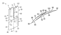
- FIG. 3 is a top view of a front blade and a rear blade of the tandem blade of FIG. 2 ;
- FIG. 4 is a perspective view of the tandem blade stacked on top of the base of the tandem blade of FIG. 2 ;
- FIG. 5 is a view of a front blade and a rear blade of another tandem blade embodiment.
- FIG. 6 is a perspective view of an embodiment of a tandem blade having a shroud.
- the gas turbine engine 10 may be a two-spool turbofan engine that includes a fan section 12 , a compressor section 14 disposed adjacent to the fan section 12 , a combustor section 16 disposed adjacent to the compressor section 14 , and a turbine section 18 disposed adjacent to the combustor section.
- Alternative gas turbine engines may include an augmenter section (not shown) among other systems or features.
- the fan section 12 , the compressor section 14 , and the turbine section 18 may be rotatable about an axis A.
- the fan section 12 drives air along a bypass flow path B, while the compressor section 14 drives air along a core flow path C for compression and communication into the combustor section 16 .
- Hot combustion gases generated within the combustor section 16 are expanded through the turbine section 18 .
- FIG. 18 Although depicted as a two-spool turbofan gas turbine engine, it should be understood that the concepts described herein are not limited to two-spool turbofan engines and these teachings could extend to other types of engines, including but not limited to, three-spool engine architectures.
- a tandem tip blade 20 may be provided with the gas turbine engine 10 .
- the tandem tip blade 20 may be provided with a blade that is incorporated into at least one of the fan section 12 , the compressor section 14 , and the turbine section 18 .
- the tandem tip blade 20 may be incorporated into a rotating component such as a rotor that is provided with at least one of the fan section 12 , the compressor section 14 , and the turbine section 18 .
- the tandem tip blade 20 may be circumferentially disposed about the axis A. The tandem tip blade 20 improves the operational range and performance of the gas turbine engine 10 .
- the tandem tip blade 20 may enable the removal of stators and combine two rotors into the tandem tip blade 20 and maintain loading of two stages and reduce leakage flow and improve performance of the gas turbine engine 10 .
- the tandem tip blade 20 includes a main body 22 , a front blade 24 extending from the main body 22 , and a rear blade 26 extending from the main body 22 .
- the main body 22 extends from a base or platform along a span wise axis 30 .
- the base or platform is connected to a dovetail or other connecting feature that connects the tandem tip blade 20 to a rotating component.
- the span wise axis 30 may define a stacking line of the tandem tip blade 20 .
- the main body 22 includes a main body leading edge 40 , a main body trailing edge 42 , a main body pressure side 44 , and a main body suction side 46 .
- the main body leading edge 40 is disposed opposite the main body trailing edge 42 .
- the main body leading edge 40 and the main body trailing edge 42 extend from a main body base 50 towards a main body end 52 .
- the main body base 50 defines a root of the tandem tip blade 20 .
- the main body end 52 is disposed opposite the main body base 50 .
- the main body end 52 defines a mid-span region that may extend above and/or below the mid-span or mid-chord region of the tandem tip blade 20 .
- the main body pressure side 44 extends axially between the main body leading edge 40 and the main body trailing edge 42 .
- the main body pressure side 44 extends between the main body base 50 and the main body end 52 .
- the main body suction side 46 is disposed opposite the main body pressure side 44 .
- the main body suction side 46 extends axially between the main body leading edge 40 and the main body trailing edge 42 .
- the main body suction side 46 extends between the main body base 50 and the main body end 52 .
- the main body 22 has a maximum main body thickness, t mb .
- the maximum main body thickness, t mb extends between the main body pressure side 44 and the main body suction side 46 .
- the front blade 24 extends radially from the main body 22 .
- the front blade 24 also extends axially from the main body leading edge 40 towards the mid-chord of the main body 22 or the span wise axis 30 .
- the front blade 24 includes a front blade leading edge 60 , a front blade trailing edge 62 , a front blade pressure side 64 ( FIG. 3 ), and a front blade suction side 66 ( FIG. 3 ).
- the front blade leading edge 60 is disposed opposite the front blade trailing edge 62 .
- the front blade leading edge 60 is disposed opposite the front blade trailing edge 62 .
- the front blade leading edge 60 is configured as a smooth continuation or smooth extension of the main body leading edge 40 .
- the front blade trailing edge 62 is disposed along the span wise axis 30 .
- the front blade leading edge 60 and the front blade trailing edge 62 extend from a front blade base 70 towards a front blade tip 72 .
- the front blade base 70 may be spaced apart from the main body end 52 by a transition region 80 .
- the front blade base 70 may abut or be joined to the main body end 52 such that the front blade 24 directly extends from the main body end 52 , as shown in FIG. 2 .
- the front blade pressure side 64 extends axially between the front blade leading edge 60 and the front blade trailing edge 62 .
- the front blade pressure side 64 extends between the front blade base 70 and the front blade tip 72 .
- the front blade suction side 66 is disposed opposite the front blade pressure side 64 .
- the front blade suction side 66 extends axially between the front blade leading edge 60 and the front blade trailing edge 62 .
- the front blade suction side 66 extends between the front blade base 70 and the front blade tip 72 .
- the front blade tip 72 extends between the front blade leading edge 60 , the front blade trailing edge 62 , the front blade pressure side 64 , and the front blade suction side 66 .
- the front blade 24 has a maximum front blade thickness, t 1 .
- the maximum front blade thickness, t 1 extends between the front blade pressure side 64 and the front blade suction side 66 .
- the rear blade 26 extends radially from the main body 22 .
- the rear blade 26 is spaced apart from the front blade 24 , while still extending from the main body 22 .
- the rear blade 26 extends axially from the main body trailing edge 42 towards the mid-chord of the main body 22 or the span wise axis 30 .
- the rear blade 26 includes a rear blade leading edge 90 , a rear blade trailing edge 92 , a rear blade pressure side 94 ( FIG. 3 ), and a rear blade suction side 96 ( FIG. 3 ).
- the rear blade leading edge 90 is disposed opposite the rear blade trailing edge 92 .
- the rear blade leading edge 90 is disposed along the span wise axis 30 .
- the rear blade leading edge 90 is disposed proximate the front blade trailing edge 62 .
- the rear blade leading edge 90 is disposed adjacent to and is circumferentially offset from the front blade trailing edge 62 such that the rear blade leading edge 90 at least partially axially overlaps the front blade trailing edge 62 within an overlap region 110 .
- the front blade trailing edge 62 is located downstream relative to the rear blade leading edge 90 .
- the rear blade leading edge 90 is disposed proximate the front blade pressure side 64 . In at least one embodiment, the rear blade leading edge 90 is disposed proximate the front blade suction side 66 .
- the rear blade leading edge 90 may abut the front blade trailing edge 62 .
- the rear blade leading edge 90 extends directly from the front blade trailing edge 62 .
- the rear blade trailing edge 92 is a smooth extension of the main body trailing edge 42 .
- the rear blade leading edge 90 and the rear blade trailing edge 92 extend from the rear blade base 100 ( FIG. 6 ) towards the rear blade tip 102 .
- the rear blade base 100 may be spaced apart from the main body end 52 by the transition region 80 .
- the transition region 80 extends between a location along the span, the main body end 52 , the front blade base 70 , and the rear blade base 100 .
- the transition region 80 provides a smooth transition between the main body 22 and the front blade 24 and the rear blade 26 .
- the rear blade base 100 may abut or be joined to the main body end 52 such that the rear blade 26 directly extends from the main body end 52 , as shown in FIG. 3 .
- the rear blade pressure side 94 extends axially between the rear blade leading edge 90 and the rear blade trailing edge 92 .
- the rear blade pressure side 94 extends between the rear blade base 100 and the rear blade tip 102 .
- the rear blade suction side 96 is disposed opposite the rear blade pressure side 94 .
- the rear blade suction side 96 extends axially between the rear blade leading edge 90 and the rear blade trailing edge 92 .
- the rear blade suction side 96 extends between the rear blade base 100 and the rear blade tip 102 .
- the rear blade tip 102 extends between the rear blade leading edge 90 , the rear blade trailing edge 92 , the rear blade pressure side 94 , and the rear blade suction side 96 .
- the front blade 24 has a substantially similar height as the rear blade 26 .
- the front blade 24 and the rear blade 26 have varying heights that extend from the tandem blade base towards the tandem blade tip.
- the front blade tip 72 may be disposed above the rear blade tip 102 or the front blade tip 72 may be disposed below the rear blade tip 102 .
- the rear blade 26 has a maximum rear blade thickness, t 2 .
- the maximum rear blade thickness, t 2 extends between the rear blade pressure side 94 and the rear blade suction side 96 .
- the main body thickness, t mb is greater than the front blade maximum thickness, t 1 , and the rear blade maximum thickness, t 2 .
- the rear blade 26 is circumferentially spaced apart from the front blade 24 .
- the rear blade 26 is circumferentially offset from the front blade 24 in a direction that extends from the front blade suction side 66 towards the front blade pressure side 64 such that the rear blade 26 is disposed proximate the front blade pressure side 64 .
- the rear blade leading edge 90 is disposed proximate the front blade pressure side 64 .
- the rear blade 26 is circumferentially offset from the front blade 24 in a direction that extends from the front blade pressure side 64 towards the front blade suction side 66 , such that the rear blade is disposed proximate the front blade suction side 66 .
- the front blade trailing edge 62 is disposed proximate the rear blade suction side 96 .
- the front blade 24 and the rear blade 26 extending from the main body 22 increases solidity of the tandem tip blade 20 near the front blade tip 72 and the rear blade tip 102 .
- the increase in solidity delays stall of the gas turbine engine.
- the front blade 24 may diffuse or slow down the supersonic flow and the rear blade 26 turns the airflow and experiences the loading.
- the front blade 24 is shaped such that the front blade 24 has a front blade thickness and no camber angle for transonic inlet flow.
- the front blade 24 may be substantially flat in such an embodiment.
- the rear blade 26 is shaped such that the rear blade 26 has a rear blade thickness and a camber angle for at least one of subsonic and low transonic passage flow.
- the rear blade 26 turns the airflow in such an embodiment.
- the front blade 24 is shaped such that the front blade 24 has a front blade thickness and camber angle for subsonic inlet flow.
- the rear blade 26 is shaped such that the rear blade 26 has a rear blade thickness with a camber angle.
- the front blade 24 turns the airflow in such an embodiment.
- This tandem blade shape may improve stall margin of the tandem tip blade 20 and the stall margin of the overall gas turbine engine that incorporates the tandem tip blade 20 by changing the boundary layer structure on the tandem blade surface.
- the tandem blade shape may also reduce the losses of leakage due to the elimination of stationary parts between stages.
- a shroud 120 may be provided.
- the shroud 120 may be disposed on at least one of the front blade 24 and the rear blade 26 .
- the shroud 120 may be integrally formed with at least one of the front blade tip 72 and the rear blade tip 102 .
- the shroud 120 may aid in improving a forced response of the tandem tip blade 20 during the vibration due to unsteady flow.
Landscapes
- Engineering & Computer Science (AREA)
- Mechanical Engineering (AREA)
- General Engineering & Computer Science (AREA)
- Chemical & Material Sciences (AREA)
- Combustion & Propulsion (AREA)
- Physics & Mathematics (AREA)
- Fluid Mechanics (AREA)
- Turbine Rotor Nozzle Sealing (AREA)
- Structures Of Non-Positive Displacement Pumps (AREA)
Abstract
Description
Claims (17)
Priority Applications (2)
| Application Number | Priority Date | Filing Date | Title |
|---|---|---|---|
| US15/160,165 US10151322B2 (en) | 2016-05-20 | 2016-05-20 | Tandem tip blade |
| EP17172283.8A EP3255244B1 (en) | 2016-05-20 | 2017-05-22 | Tandem blade and corresponding gas turbine engine |
Applications Claiming Priority (1)
| Application Number | Priority Date | Filing Date | Title |
|---|---|---|---|
| US15/160,165 US10151322B2 (en) | 2016-05-20 | 2016-05-20 | Tandem tip blade |
Publications (2)
| Publication Number | Publication Date |
|---|---|
| US20170335860A1 US20170335860A1 (en) | 2017-11-23 |
| US10151322B2 true US10151322B2 (en) | 2018-12-11 |
Family
ID=58745170
Family Applications (1)
| Application Number | Title | Priority Date | Filing Date |
|---|---|---|---|
| US15/160,165 Active 2037-01-03 US10151322B2 (en) | 2016-05-20 | 2016-05-20 | Tandem tip blade |
Country Status (2)
| Country | Link |
|---|---|
| US (1) | US10151322B2 (en) |
| EP (1) | EP3255244B1 (en) |
Families Citing this family (2)
| Publication number | Priority date | Publication date | Assignee | Title |
|---|---|---|---|---|
| WO2015142200A1 (en) * | 2014-03-18 | 2015-09-24 | General Electric Company | Exhaust gas diffuser with main struts and small struts |
| CN120027094A (en) * | 2025-04-18 | 2025-05-23 | 常州祥明智能动力股份有限公司 | Axial flow fan and design method thereof |
Citations (19)
| Publication number | Priority date | Publication date | Assignee | Title |
|---|---|---|---|---|
| US3756739A (en) * | 1970-06-12 | 1973-09-04 | Etude Soc Dev Turbines Hydraul | Turbine-pumps |
| US4102600A (en) * | 1975-04-09 | 1978-07-25 | Maschinenfabrik Augsburg-Nurnberg Aktiengesellschaft | Moving blade ring of high circumferential speed for thermal axially passed through turbines |
| US4687416A (en) * | 1981-02-13 | 1987-08-18 | Spranger Guenther | Method and device for decreasing the flow resistance on wings particularly aerofoils and blades of turbomachines exposed to gas flux such as air |
| SU1758247A1 (en) | 1989-11-14 | 1992-08-30 | Ленинградский Кораблестроительный Институт | Axial turbomachine |
| US5236307A (en) * | 1991-07-27 | 1993-08-17 | Rolls-Royce Plc | Variable geometry rotors for turbo machines |
| JPH07279887A (en) | 1994-04-15 | 1995-10-27 | Ishikawajima Harima Heavy Ind Co Ltd | Axial air compressor |
| US6099249A (en) * | 1996-08-09 | 2000-08-08 | Kawasaki Jukogyo Kabushiki | Structure of output section of jet propulsion engine or gas turbine |
| US6350103B1 (en) * | 1998-04-27 | 2002-02-26 | Kawasaki Jukogyo Kabushiki Kaisha | Jet engine booster structure |
| US6715983B2 (en) * | 2001-09-27 | 2004-04-06 | General Electric Company | Method and apparatus for reducing distortion losses induced to gas turbine engine airflow |
| WO2005040559A1 (en) | 2003-10-17 | 2005-05-06 | Paolo Pietricola | High lift rotor or stator blades with multiple adjacent airfoils cross-section |
| US7396208B1 (en) * | 2005-02-15 | 2008-07-08 | Hussain Mahmood H | Divided blade rotor |
| US20080298974A1 (en) * | 2007-05-29 | 2008-12-04 | Volker Guemmer | Blade of a fluid-flow machine featuring a multi-profile design |
| US20120148396A1 (en) * | 2010-12-08 | 2012-06-14 | Rolls-Royce Deutschland Ltd & Co Kg | Fluid-flow machine - blade with hybrid profile configuration |
| CN103953579A (en) | 2014-04-24 | 2014-07-30 | 中国科学院工程热物理研究所 | Gas compressor rotor blade with top slit and design method |
| US20140328675A1 (en) * | 2013-05-03 | 2014-11-06 | Techspace Aero S.A. | Axial Turbomachine Stator with Ailerons at the Blade Roots |
| WO2015072256A1 (en) | 2013-11-15 | 2015-05-21 | 株式会社Ihi | Vane structure for axial flow turbomachine and gas turbine engine |
| US20160130973A1 (en) * | 2014-11-10 | 2016-05-12 | Rolls-Royce Plc | Guide vane |
| US20160245091A1 (en) * | 2013-10-31 | 2016-08-25 | United Technologies Corporation | Gas turbine engine airfoil with auxiliary flow channel |
| US9617868B2 (en) * | 2013-02-26 | 2017-04-11 | Rolls-Royce North American Technologies, Inc. | Gas turbine engine variable geometry flow component |
-
2016
- 2016-05-20 US US15/160,165 patent/US10151322B2/en active Active
-
2017
- 2017-05-22 EP EP17172283.8A patent/EP3255244B1/en active Active
Patent Citations (21)
| Publication number | Priority date | Publication date | Assignee | Title |
|---|---|---|---|---|
| US3756739A (en) * | 1970-06-12 | 1973-09-04 | Etude Soc Dev Turbines Hydraul | Turbine-pumps |
| US4102600A (en) * | 1975-04-09 | 1978-07-25 | Maschinenfabrik Augsburg-Nurnberg Aktiengesellschaft | Moving blade ring of high circumferential speed for thermal axially passed through turbines |
| US4687416A (en) * | 1981-02-13 | 1987-08-18 | Spranger Guenther | Method and device for decreasing the flow resistance on wings particularly aerofoils and blades of turbomachines exposed to gas flux such as air |
| SU1758247A1 (en) | 1989-11-14 | 1992-08-30 | Ленинградский Кораблестроительный Институт | Axial turbomachine |
| US5236307A (en) * | 1991-07-27 | 1993-08-17 | Rolls-Royce Plc | Variable geometry rotors for turbo machines |
| JPH07279887A (en) | 1994-04-15 | 1995-10-27 | Ishikawajima Harima Heavy Ind Co Ltd | Axial air compressor |
| US6099249A (en) * | 1996-08-09 | 2000-08-08 | Kawasaki Jukogyo Kabushiki | Structure of output section of jet propulsion engine or gas turbine |
| US6350103B1 (en) * | 1998-04-27 | 2002-02-26 | Kawasaki Jukogyo Kabushiki Kaisha | Jet engine booster structure |
| US6715983B2 (en) * | 2001-09-27 | 2004-04-06 | General Electric Company | Method and apparatus for reducing distortion losses induced to gas turbine engine airflow |
| WO2005040559A1 (en) | 2003-10-17 | 2005-05-06 | Paolo Pietricola | High lift rotor or stator blades with multiple adjacent airfoils cross-section |
| US7396208B1 (en) * | 2005-02-15 | 2008-07-08 | Hussain Mahmood H | Divided blade rotor |
| US20080298974A1 (en) * | 2007-05-29 | 2008-12-04 | Volker Guemmer | Blade of a fluid-flow machine featuring a multi-profile design |
| US20120148396A1 (en) * | 2010-12-08 | 2012-06-14 | Rolls-Royce Deutschland Ltd & Co Kg | Fluid-flow machine - blade with hybrid profile configuration |
| US9617868B2 (en) * | 2013-02-26 | 2017-04-11 | Rolls-Royce North American Technologies, Inc. | Gas turbine engine variable geometry flow component |
| US20140328675A1 (en) * | 2013-05-03 | 2014-11-06 | Techspace Aero S.A. | Axial Turbomachine Stator with Ailerons at the Blade Roots |
| US9739154B2 (en) * | 2013-05-03 | 2017-08-22 | Safran Aero Boosters Sa | Axial turbomachine stator with ailerons at the blade roots |
| US20160245091A1 (en) * | 2013-10-31 | 2016-08-25 | United Technologies Corporation | Gas turbine engine airfoil with auxiliary flow channel |
| WO2015072256A1 (en) | 2013-11-15 | 2015-05-21 | 株式会社Ihi | Vane structure for axial flow turbomachine and gas turbine engine |
| US20160177728A1 (en) | 2013-11-15 | 2016-06-23 | Ihi Corporation | Vane structure for axial flow turbomachine and gas turbine engine |
| CN103953579A (en) | 2014-04-24 | 2014-07-30 | 中国科学院工程热物理研究所 | Gas compressor rotor blade with top slit and design method |
| US20160130973A1 (en) * | 2014-11-10 | 2016-05-12 | Rolls-Royce Plc | Guide vane |
Non-Patent Citations (1)
| Title |
|---|
| European Search Report for EP Application No. 17172283.8; dated Nov. 9, 2017; 9 pages. |
Also Published As
| Publication number | Publication date |
|---|---|
| EP3255244A1 (en) | 2017-12-13 |
| US20170335860A1 (en) | 2017-11-23 |
| EP3255244B1 (en) | 2021-09-22 |
Similar Documents
| Publication | Publication Date | Title |
|---|---|---|
| JP6025269B2 (en) | Compressor airfoil with tip angle | |
| US10018050B2 (en) | Turbomachine rotor blade | |
| EP3026214B1 (en) | Airfoil with stepped spanwise thickness distribution | |
| US20210239132A1 (en) | Variable-cycle compressor with a splittered rotor | |
| US12320274B2 (en) | Compressor stator with leading edge fillet | |
| US20100254797A1 (en) | Endwall with leading-edge hump | |
| US9835166B2 (en) | Array of flow-directing elements for a gas turbine compressor | |
| EP2990601B1 (en) | Method for improving gas turbine engine performance | |
| JP2010156335A (en) | Method and device concerning contour of improved turbine blade platform | |
| EP3208467B1 (en) | Compressor rotor for supersonic flutter and/or resonant stress mitigation | |
| JP2008138677A (en) | The latest booster stator vane | |
| JP2008138679A (en) | The latest booster system | |
| JP2015183691A (en) | Gas turbine blade | |
| US20170306768A1 (en) | Turbine engine shroud assembly | |
| US20180017019A1 (en) | Turbofan engine wth a splittered rotor fan | |
| RU2727823C2 (en) | Turbomachine rotor blade, disc with blades, rotor and turbomachine | |
| EP2998509A1 (en) | Endwall contouring for airfoil rows with varying airfoil geometries | |
| US7789631B2 (en) | Compressor of a gas turbine and gas turbine | |
| US10151322B2 (en) | Tandem tip blade | |
| EP3296508B1 (en) | Full-span forward swept airfoils for gas turbine engines | |
| US10935041B2 (en) | Pressure recovery axial-compressor blading | |
| EP2880280A1 (en) | Airfoil design having localized suction side curvatures |
Legal Events
| Date | Code | Title | Description |
|---|---|---|---|
| AS | Assignment |
Owner name: UNITED TECHNOLOGIES CORPORATION, CONNECTICUT Free format text: ASSIGNMENT OF ASSIGNORS INTEREST;ASSIGNORS:VOYTOVYCH, DMYTRO MYKOLAYOVYCH;STAROSELSKY, ALEXANDER;GRAY, ERIC D.;REEL/FRAME:038657/0113 Effective date: 20160519 |
|
| STCF | Information on status: patent grant |
Free format text: PATENTED CASE |
|
| AS | Assignment |
Owner name: RAYTHEON TECHNOLOGIES CORPORATION, MASSACHUSETTS Free format text: CHANGE OF NAME;ASSIGNOR:UNITED TECHNOLOGIES CORPORATION;REEL/FRAME:054062/0001 Effective date: 20200403 |
|
| AS | Assignment |
Owner name: RAYTHEON TECHNOLOGIES CORPORATION, CONNECTICUT Free format text: CORRECTIVE ASSIGNMENT TO CORRECT THE AND REMOVE PATENT APPLICATION NUMBER 11886281 AND ADD PATENT APPLICATION NUMBER 14846874. TO CORRECT THE RECEIVING PARTY ADDRESS PREVIOUSLY RECORDED AT REEL: 054062 FRAME: 0001. ASSIGNOR(S) HEREBY CONFIRMS THE CHANGE OF ADDRESS;ASSIGNOR:UNITED TECHNOLOGIES CORPORATION;REEL/FRAME:055659/0001 Effective date: 20200403 |
|
| MAFP | Maintenance fee payment |
Free format text: PAYMENT OF MAINTENANCE FEE, 4TH YEAR, LARGE ENTITY (ORIGINAL EVENT CODE: M1551); ENTITY STATUS OF PATENT OWNER: LARGE ENTITY Year of fee payment: 4 |
|
| AS | Assignment |
Owner name: RTX CORPORATION, CONNECTICUT Free format text: CHANGE OF NAME;ASSIGNOR:RAYTHEON TECHNOLOGIES CORPORATION;REEL/FRAME:064714/0001 Effective date: 20230714 |