US10151240B2 - Mid-turbine frame buffer system - Google Patents
Mid-turbine frame buffer system Download PDFInfo
- Publication number
- US10151240B2 US10151240B2 US15/084,970 US201615084970A US10151240B2 US 10151240 B2 US10151240 B2 US 10151240B2 US 201615084970 A US201615084970 A US 201615084970A US 10151240 B2 US10151240 B2 US 10151240B2
- Authority
- US
- United States
- Prior art keywords
- air
- compartment
- bearing
- mid
- turbine
- Prior art date
- Legal status (The legal status is an assumption and is not a legal conclusion. Google has not performed a legal analysis and makes no representation as to the accuracy of the status listed.)
- Active, expires
Links
Images


Classifications
-
- F—MECHANICAL ENGINEERING; LIGHTING; HEATING; WEAPONS; BLASTING
- F02—COMBUSTION ENGINES; HOT-GAS OR COMBUSTION-PRODUCT ENGINE PLANTS
- F02C—GAS-TURBINE PLANTS; AIR INTAKES FOR JET-PROPULSION PLANTS; CONTROLLING FUEL SUPPLY IN AIR-BREATHING JET-PROPULSION PLANTS
- F02C7/00—Features, components parts, details or accessories, not provided for in, or of interest apart form groups F02C1/00 - F02C6/00; Air intakes for jet-propulsion plants
- F02C7/06—Arrangements of bearings; Lubricating
-
- F—MECHANICAL ENGINEERING; LIGHTING; HEATING; WEAPONS; BLASTING
- F01—MACHINES OR ENGINES IN GENERAL; ENGINE PLANTS IN GENERAL; STEAM ENGINES
- F01D—NON-POSITIVE DISPLACEMENT MACHINES OR ENGINES, e.g. STEAM TURBINES
- F01D11/00—Preventing or minimising internal leakage of working-fluid, e.g. between stages
- F01D11/005—Sealing means between non relatively rotating elements
-
- F—MECHANICAL ENGINEERING; LIGHTING; HEATING; WEAPONS; BLASTING
- F01—MACHINES OR ENGINES IN GENERAL; ENGINE PLANTS IN GENERAL; STEAM ENGINES
- F01D—NON-POSITIVE DISPLACEMENT MACHINES OR ENGINES, e.g. STEAM TURBINES
- F01D11/00—Preventing or minimising internal leakage of working-fluid, e.g. between stages
- F01D11/02—Preventing or minimising internal leakage of working-fluid, e.g. between stages by non-contact sealings, e.g. of labyrinth type
- F01D11/04—Preventing or minimising internal leakage of working-fluid, e.g. between stages by non-contact sealings, e.g. of labyrinth type using sealing fluid, e.g. steam
-
- F—MECHANICAL ENGINEERING; LIGHTING; HEATING; WEAPONS; BLASTING
- F01—MACHINES OR ENGINES IN GENERAL; ENGINE PLANTS IN GENERAL; STEAM ENGINES
- F01D—NON-POSITIVE DISPLACEMENT MACHINES OR ENGINES, e.g. STEAM TURBINES
- F01D25/00—Component parts, details, or accessories, not provided for in, or of interest apart from, other groups
- F01D25/16—Arrangement of bearings; Supporting or mounting bearings in casings
-
- F—MECHANICAL ENGINEERING; LIGHTING; HEATING; WEAPONS; BLASTING
- F01—MACHINES OR ENGINES IN GENERAL; ENGINE PLANTS IN GENERAL; STEAM ENGINES
- F01D—NON-POSITIVE DISPLACEMENT MACHINES OR ENGINES, e.g. STEAM TURBINES
- F01D25/00—Component parts, details, or accessories, not provided for in, or of interest apart from, other groups
- F01D25/18—Lubricating arrangements
- F01D25/183—Sealing means
-
- F—MECHANICAL ENGINEERING; LIGHTING; HEATING; WEAPONS; BLASTING
- F01—MACHINES OR ENGINES IN GENERAL; ENGINE PLANTS IN GENERAL; STEAM ENGINES
- F01D—NON-POSITIVE DISPLACEMENT MACHINES OR ENGINES, e.g. STEAM TURBINES
- F01D25/00—Component parts, details, or accessories, not provided for in, or of interest apart from, other groups
- F01D25/18—Lubricating arrangements
- F01D25/20—Lubricating arrangements using lubrication pumps
-
- F—MECHANICAL ENGINEERING; LIGHTING; HEATING; WEAPONS; BLASTING
- F01—MACHINES OR ENGINES IN GENERAL; ENGINE PLANTS IN GENERAL; STEAM ENGINES
- F01D—NON-POSITIVE DISPLACEMENT MACHINES OR ENGINES, e.g. STEAM TURBINES
- F01D25/00—Component parts, details, or accessories, not provided for in, or of interest apart from, other groups
- F01D25/28—Supporting or mounting arrangements, e.g. for turbine casing
-
- F—MECHANICAL ENGINEERING; LIGHTING; HEATING; WEAPONS; BLASTING
- F02—COMBUSTION ENGINES; HOT-GAS OR COMBUSTION-PRODUCT ENGINE PLANTS
- F02C—GAS-TURBINE PLANTS; AIR INTAKES FOR JET-PROPULSION PLANTS; CONTROLLING FUEL SUPPLY IN AIR-BREATHING JET-PROPULSION PLANTS
- F02C3/00—Gas-turbine plants characterised by the use of combustion products as the working fluid
- F02C3/04—Gas-turbine plants characterised by the use of combustion products as the working fluid having a turbine driving a compressor
- F02C3/10—Gas-turbine plants characterised by the use of combustion products as the working fluid having a turbine driving a compressor with another turbine driving an output shaft but not driving the compressor
-
- F—MECHANICAL ENGINEERING; LIGHTING; HEATING; WEAPONS; BLASTING
- F02—COMBUSTION ENGINES; HOT-GAS OR COMBUSTION-PRODUCT ENGINE PLANTS
- F02C—GAS-TURBINE PLANTS; AIR INTAKES FOR JET-PROPULSION PLANTS; CONTROLLING FUEL SUPPLY IN AIR-BREATHING JET-PROPULSION PLANTS
- F02C6/00—Plural gas-turbine plants; Combinations of gas-turbine plants with other apparatus; Adaptations of gas-turbine plants for special use
- F02C6/04—Gas-turbine plants providing heated or pressurised working fluid for other apparatus, e.g. without mechanical power output
- F02C6/06—Gas-turbine plants providing heated or pressurised working fluid for other apparatus, e.g. without mechanical power output providing compressed gas
- F02C6/08—Gas-turbine plants providing heated or pressurised working fluid for other apparatus, e.g. without mechanical power output providing compressed gas the gas being bled from the gas-turbine compressor
-
- F—MECHANICAL ENGINEERING; LIGHTING; HEATING; WEAPONS; BLASTING
- F02—COMBUSTION ENGINES; HOT-GAS OR COMBUSTION-PRODUCT ENGINE PLANTS
- F02C—GAS-TURBINE PLANTS; AIR INTAKES FOR JET-PROPULSION PLANTS; CONTROLLING FUEL SUPPLY IN AIR-BREATHING JET-PROPULSION PLANTS
- F02C7/00—Features, components parts, details or accessories, not provided for in, or of interest apart form groups F02C1/00 - F02C6/00; Air intakes for jet-propulsion plants
- F02C7/20—Mounting or supporting of plant; Accommodating heat expansion or creep
-
- F—MECHANICAL ENGINEERING; LIGHTING; HEATING; WEAPONS; BLASTING
- F02—COMBUSTION ENGINES; HOT-GAS OR COMBUSTION-PRODUCT ENGINE PLANTS
- F02C—GAS-TURBINE PLANTS; AIR INTAKES FOR JET-PROPULSION PLANTS; CONTROLLING FUEL SUPPLY IN AIR-BREATHING JET-PROPULSION PLANTS
- F02C7/00—Features, components parts, details or accessories, not provided for in, or of interest apart form groups F02C1/00 - F02C6/00; Air intakes for jet-propulsion plants
- F02C7/28—Arrangement of seals
-
- F—MECHANICAL ENGINEERING; LIGHTING; HEATING; WEAPONS; BLASTING
- F02—COMBUSTION ENGINES; HOT-GAS OR COMBUSTION-PRODUCT ENGINE PLANTS
- F02K—JET-PROPULSION PLANTS
- F02K3/00—Plants including a gas turbine driving a compressor or a ducted fan
- F02K3/02—Plants including a gas turbine driving a compressor or a ducted fan in which part of the working fluid by-passes the turbine and combustion chamber
- F02K3/04—Plants including a gas turbine driving a compressor or a ducted fan in which part of the working fluid by-passes the turbine and combustion chamber the plant including ducted fans, i.e. fans with high volume, low pressure outputs, for augmenting the jet thrust, e.g. of double-flow type
- F02K3/06—Plants including a gas turbine driving a compressor or a ducted fan in which part of the working fluid by-passes the turbine and combustion chamber the plant including ducted fans, i.e. fans with high volume, low pressure outputs, for augmenting the jet thrust, e.g. of double-flow type with front fan
-
- F—MECHANICAL ENGINEERING; LIGHTING; HEATING; WEAPONS; BLASTING
- F16—ENGINEERING ELEMENTS AND UNITS; GENERAL MEASURES FOR PRODUCING AND MAINTAINING EFFECTIVE FUNCTIONING OF MACHINES OR INSTALLATIONS; THERMAL INSULATION IN GENERAL
- F16J—PISTONS; CYLINDERS; SEALINGS
- F16J15/00—Sealings
- F16J15/16—Sealings between relatively-moving surfaces
- F16J15/40—Sealings between relatively-moving surfaces by means of fluid
-
- F—MECHANICAL ENGINEERING; LIGHTING; HEATING; WEAPONS; BLASTING
- F05—INDEXING SCHEMES RELATING TO ENGINES OR PUMPS IN VARIOUS SUBCLASSES OF CLASSES F01-F04
- F05D—INDEXING SCHEME FOR ASPECTS RELATING TO NON-POSITIVE-DISPLACEMENT MACHINES OR ENGINES, GAS-TURBINES OR JET-PROPULSION PLANTS
- F05D2220/00—Application
- F05D2220/30—Application in turbines
- F05D2220/36—Application in turbines specially adapted for the fan of turbofan engines
-
- F—MECHANICAL ENGINEERING; LIGHTING; HEATING; WEAPONS; BLASTING
- F05—INDEXING SCHEMES RELATING TO ENGINES OR PUMPS IN VARIOUS SUBCLASSES OF CLASSES F01-F04
- F05D—INDEXING SCHEME FOR ASPECTS RELATING TO NON-POSITIVE-DISPLACEMENT MACHINES OR ENGINES, GAS-TURBINES OR JET-PROPULSION PLANTS
- F05D2240/00—Components
- F05D2240/55—Seals
- F05D2240/56—Brush seals
-
- F—MECHANICAL ENGINEERING; LIGHTING; HEATING; WEAPONS; BLASTING
- F05—INDEXING SCHEMES RELATING TO ENGINES OR PUMPS IN VARIOUS SUBCLASSES OF CLASSES F01-F04
- F05D—INDEXING SCHEME FOR ASPECTS RELATING TO NON-POSITIVE-DISPLACEMENT MACHINES OR ENGINES, GAS-TURBINES OR JET-PROPULSION PLANTS
- F05D2260/00—Function
- F05D2260/98—Lubrication
-
- F—MECHANICAL ENGINEERING; LIGHTING; HEATING; WEAPONS; BLASTING
- F05—INDEXING SCHEMES RELATING TO ENGINES OR PUMPS IN VARIOUS SUBCLASSES OF CLASSES F01-F04
- F05D—INDEXING SCHEME FOR ASPECTS RELATING TO NON-POSITIVE-DISPLACEMENT MACHINES OR ENGINES, GAS-TURBINES OR JET-PROPULSION PLANTS
- F05D2300/00—Materials; Properties thereof
- F05D2300/20—Oxide or non-oxide ceramics
- F05D2300/22—Non-oxide ceramics
- F05D2300/224—Carbon, e.g. graphite
Definitions
- This disclosure relates to a mid-turbine frame buffer system for a gas turbine engine.
- a mid-turbine frame is a structural case that is used to support the aft end of the high spool shaft of a turbofan engine.
- the mid-turbine frame is located between the high pressure turbine and low pressure turbine, a location where the core flowpath pressure and temperature are high.
- the static mid-turbine frame supports a rotating high speed shaft through a bearing enclosed in a buffered bearing compartment. Since the bearing must be cooled and lubricated with a constant oil flow, seals are used to contain the oil at static-to-rotating interfaces.
- the buffer air pressure outside of the bearing compartment must remain higher than the pressure inside the compartment so that air always leaks into the compartment, not out, so that the oil is contained within the bearing compartment.
- a gas turbine engine includes a fan.
- a compressor section is fluidly connected to the fan.
- a combustor is fluidly connected to the compressor section and has first and second pressure compressors.
- a turbine section is fluidly connected to the combustor.
- the turbine section includes a first pressure turbine coupled to the first compressor via a first shaft.
- a second pressure turbine coupled to the second compressor via a second shaft.
- a mid-turbine frame is positioned between the second pressure turbine and the first pressure turbine.
- the mid-turbine frame supports one of the first and second shafts by a bearing.
- a geared architecture interconnects at least one of the first and second turbines and the fan.
- a mid-turbine frame buffer system includes an air compartment.
- a bearing compartment is arranged radially inward of the mid-turbine frame.
- the bearing compartment is arranged within the air compartment.
- the bearing compartment includes a seal assembly provided adjacent the bearing and it separates the bearing compartment from the air compartment.
- the air compartment includes two or more air seals.
- the compressor section is fluidly connected to the air compartment and is configured to provide pressurized air to the seal assembly in the air compartment to buffer the bearing compartment.
- the mid-turbine frame includes a member that is arranged in a core flow path. The member provides a passage that fluidly connects mid-turbine frame outer and inner areas to one another for delivering the pressurized air to the air compartment.
- the bearing is a roller bearing.
- a lubrication pump is fluidly connected to the bearing compartment by a scavenge line.
- the air seals includes at least one of a labyrinth seal and a brush seal.
- the gas turbine engine is a high bypass engine having a bypass ratio of greater than about six (6).
- the gas turbine engine includes a low Fan Pressure Ratio of less than about 1.45.
- the low pressure turbine has a pressure ratio that is greater than about 5.
- the second and first pressure turbines respectively correspond to high and low pressure turbines.
- the mid-turbine frame is arranged axially between the high and low pressure turbines.
- a lubrication pump is fluidly connected to the bearing compartment by a scavenge line.
- the seal assembly comprises first and second contact seals.
- Each of the first and second contact seals has first and second members in engagement with one another. At least one of the first and second members is constructed from a carbon material.
- the air seals includes a labyrinth seal.
- the air seals includes a brush seal.
- FIG. 2 schematically depicts a mid-turbine frame buffer system for the gas turbine engine illustrated in FIG. 1 .
- FIG. 1 schematically illustrates a gas turbine engine 20 .
- the gas turbine engine 20 is disclosed herein as a two-spool turbofan that generally incorporates a fan section 22 , a compressor section 24 , a combustor section 26 and a turbine section 28 .
- Alternative engines might include an augmentor section (not shown) among other systems or features.
- the fan section 22 drives air along a bypass flowpath B while the compressor section 24 drives air along a core flowpath C for compression and communication into the combustor section 26 then expansion through the turbine section 28 .
- FIG. 1 schematically illustrates a gas turbine engine 20 .
- the gas turbine engine 20 is disclosed herein as a two-spool turbofan that generally incorporates a fan section 22 , a compressor section 24 , a combustor section 26 and a turbine section 28 .
- Alternative engines might include an augmentor section (not shown) among other systems or features.
- the fan section 22 drives air along a bypass flowpath B while the compressor section 24 drives air along
- the engine 20 generally includes a low speed spool 30 and a high speed spool 32 mounted for rotation about an engine central longitudinal axis A relative to an engine static structure 36 via several bearing systems 38 . It should be understood that various bearing systems 38 at various locations may alternatively or additionally be provided.
- the low speed spool 30 generally includes an inner shaft 40 that interconnects a fan 42 , a low pressure compressor 44 and a low pressure turbine 46 .
- the inner shaft 40 is connected to the fan 42 through a geared architecture 48 to drive the fan 42 at a lower speed than the low speed spool 30 .
- the high speed spool 32 includes an outer shaft 50 that interconnects a high pressure compressor 52 and high pressure turbine 54 .
- a combustor 56 is arranged between the high pressure compressor 52 and the high pressure turbine 54 .
- a mid-turbine frame 57 of the engine static structure 36 is arranged generally between the high pressure turbine 54 and the low pressure turbine 46 .
- the mid-turbine frame 57 supports one or more bearing systems 38 in the turbine section 28 .
- the inner shaft 40 and the outer shaft 50 are concentric and rotate via bearing systems 38 about the engine central longitudinal axis A which is collinear with their longitudinal axes.
- the core airflow is compressed by the low pressure compressor 44 then the high pressure compressor 52 , mixed and burned with fuel in the combustor 56 , then expanded over the high pressure turbine 54 and low pressure turbine 46 .
- the mid-turbine frame 57 includes airfoils 59 which are in the core airflow path.
- the turbines 46 , 54 rotationally drive the respective low speed spool 30 and high speed spool 32 in response to the expansion.
- the engine 20 in one example a high-bypass geared aircraft engine.
- the engine 20 bypass ratio is greater than about six (6), with an example embodiment being greater than ten (10)
- the geared architecture 48 is an epicyclic gear train, such as a planetary gear system or other gear system, with a gear reduction ratio of greater than about 2.3 and the low pressure turbine 46 has a pressure ratio that is greater than about 5.
- the engine 20 bypass ratio is greater than about ten (10:1)
- the fan diameter is significantly larger than that of the low pressure compressor 44
- the low pressure turbine 46 has a pressure ratio that is greater than about 5:1.
- Low pressure turbine 46 pressure ratio is pressure measured prior to inlet of low pressure turbine 46 as related to the pressure at the outlet of the low pressure turbine 46 prior to an exhaust nozzle.
- the geared architecture 48 may be an epicycle gear train, such as a planetary gear system or other gear system, with a gear reduction ratio of greater than about 2.5:1. It should be understood, however, that the above parameters are only exemplary of one embodiment of a geared architecture engine and that the present invention is applicable to other gas turbine engines including direct drive turbofans.
- the fan section 22 of the engine 20 is designed for a particular flight condition—typically cruise at about 0.8 Mach and about 35,000 feet.
- TSFC Thrust Specific Fuel Consumption
- TSFC is the industry standard parameter of lbm of fuel being burned divided by lbf of thrust the engine produces at that minimum point.
- “Low fan pressure ratio” is the pressure ratio across the fan blade alone, without a Fan Exit Guide Vane (“FEGV”) system.
- the low fan pressure ratio as disclosed herein according to one non-limiting embodiment is less than about 1.45.
- Low corrected fan tip speed is the actual fan tip speed in ft/sec divided by an industry standard temperature correction of [(Tram ° R)/(518.7° R)] 0.5 .
- the “Low corrected fan tip speed” as disclosed herein according to one non-limiting embodiment is less than about 1150 ft/second.
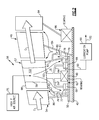
- a buffer system 58 is schematically illustrated in FIG. 2 .
- a bearing 60 is structurally supported by the mid-turbine frame 57 and supports the outer shaft 50 for rotation.
- the bearing may be, for example, a roller bearing a ball bearing or other type of bearing.
- the bearing 60 is arranged within a bearing compartment 62 , which provides an enclosure for retaining lubrication for the bearing. This enclosure is provided, for example, by walls 64 that support first and second contact seals 66 , 68 arranged on either side of the bearing 60 .
- Each of the first and second contact seals 66 , 68 includes first and second members 70 , 72 that are in engagement with one another such that no gaps are provided between the first and second members 70 , 72 .
- At least one of the first and second members 70 , 72 is constructed from a carbon material. The use of high pressure ratio face carbon seals reduces airflow into the oil compartment (as compared to conventional buffer systems), thereby eliminating the need for a conventional breather air tube.
- a lubrication pump 88 is fluidly connected to the bearing compartment 62 by a scavenge line 90 . Any air entering the bearing compartment 62 is exhausted through a vent 92 .
- the lubrication pump 88 has sufficient capacity to evacuate any small amount of leakage past the first and second contact seals 66 , 68 into the bearing compartment 62 .
- the bearing compartment 62 is enclosed within an air compartment 74 .
- a pressurized air source 75 is fluidly coupled to the air compartment 74 .
- “Pressurized” air is air that is provided by, e.g., the high pressure compressor 52 .
- the mid-turbine frame 57 includes outer and inner areas 98 , 100 arranged on opposing sides of the mid-turbine frame 57 .
- a passage 102 fluidly interconnects the inner and outer areas 98 , 100 to one another. In one example, the passage 102 is provided by the mid-turbine frame airfoil 59 .
- the air compartment 74 is provided, for example, by walls 82 that support first, second and third air seals 76 , 78 , 80 .
- the first, second and third air seals 76 , 78 , 80 respectively cooperate with first, second and third surfaces 77 , 79 , 81 .
- the first surface 77 is provided by a high pressure rotor 86 .
- the second surface 79 is provided by the outer shaft 50 .
- the third surface 81 is provided by a low pressure rotor 84 .
- the air seals are provided, for example, by one or more labyrinth/knife-edge seals and/or brush seals. In the example illustrated in FIG.
- the first seal 76 is a labyrinth seal
- the second and third air seals 78 , 80 are brush seals.
- Air seals typically are not air tight in that they may provide small gaps. Air seals are typically designed to inhibit leakage by creating a tortuous path through which the air must pass. Any air leakage past the first, second and third air seals 76 , 78 , 80 vents to the low and high pressure turbines 46 , 54 , as depicted by the arrows in FIG. 2 , which provide multiple air sinks.
- the high pressure buffer system surrounding the bearing compartment 62 can vent directly into the turbo machinery primary core flowpath C at the mid turbine frame 57 . Since the buffer air can vent directly into the core flowpath C, the number and diameter of the high pressure ratio air seals is reduced as compared to conventional turbine engines and, therefore, far less buffer airflow bypassing the turbo machinery is required. The energy in the buffer air entering the core flowpath C is captured in the downstream turbo machinery, thereby improving engine performance. In contrast, in conventional engines, the low buffer pressure systems therein must vent a larger mass flow of buffer air to a lower pressure sink in the core flowpath C downstream from turbo machinery, thereby losing the associated energy of this air and, correspondingly, negatively impacting engine efficiency.
- a turbine engine case 94 supports another bearing 96 , which rotationally supports the inner shaft 40 at a location aft of the bearing 60 .
Landscapes
- Engineering & Computer Science (AREA)
- General Engineering & Computer Science (AREA)
- Mechanical Engineering (AREA)
- Chemical & Material Sciences (AREA)
- Combustion & Propulsion (AREA)
- Turbine Rotor Nozzle Sealing (AREA)
- Sealing Using Fluids, Sealing Without Contact, And Removal Of Oil (AREA)
- Structures Of Non-Positive Displacement Pumps (AREA)
Abstract
Description
Claims (9)
Priority Applications (1)
| Application Number | Priority Date | Filing Date | Title |
|---|---|---|---|
| US15/084,970 US10151240B2 (en) | 2012-01-31 | 2016-03-30 | Mid-turbine frame buffer system |
Applications Claiming Priority (4)
| Application Number | Priority Date | Filing Date | Title |
|---|---|---|---|
| US13/362,361 US8366382B1 (en) | 2012-01-31 | 2012-01-31 | Mid-turbine frame buffer system |
| PCT/US2013/020466 WO2013147969A2 (en) | 2012-01-31 | 2013-01-07 | Mid-turbine frame buffer system |
| US13/879,471 US9382844B2 (en) | 2012-01-31 | 2013-01-07 | Mid-turbine frame buffer system |
| US15/084,970 US10151240B2 (en) | 2012-01-31 | 2016-03-30 | Mid-turbine frame buffer system |
Related Parent Applications (2)
| Application Number | Title | Priority Date | Filing Date |
|---|---|---|---|
| PCT/US2013/020466 Continuation WO2013147969A2 (en) | 2012-01-31 | 2013-01-07 | Mid-turbine frame buffer system |
| US13/879,471 Continuation US9382844B2 (en) | 2012-01-31 | 2013-01-07 | Mid-turbine frame buffer system |
Publications (2)
| Publication Number | Publication Date |
|---|---|
| US20160208697A1 US20160208697A1 (en) | 2016-07-21 |
| US10151240B2 true US10151240B2 (en) | 2018-12-11 |
Family
ID=47604520
Family Applications (3)
| Application Number | Title | Priority Date | Filing Date |
|---|---|---|---|
| US13/362,361 Active US8366382B1 (en) | 2012-01-31 | 2012-01-31 | Mid-turbine frame buffer system |
| US13/879,471 Active 2033-06-17 US9382844B2 (en) | 2012-01-31 | 2013-01-07 | Mid-turbine frame buffer system |
| US15/084,970 Active 2032-12-26 US10151240B2 (en) | 2012-01-31 | 2016-03-30 | Mid-turbine frame buffer system |
Family Applications Before (2)
| Application Number | Title | Priority Date | Filing Date |
|---|---|---|---|
| US13/362,361 Active US8366382B1 (en) | 2012-01-31 | 2012-01-31 | Mid-turbine frame buffer system |
| US13/879,471 Active 2033-06-17 US9382844B2 (en) | 2012-01-31 | 2013-01-07 | Mid-turbine frame buffer system |
Country Status (3)
| Country | Link |
|---|---|
| US (3) | US8366382B1 (en) |
| EP (1) | EP2809908B1 (en) |
| WO (1) | WO2013147969A2 (en) |
Cited By (2)
| Publication number | Priority date | Publication date | Assignee | Title |
|---|---|---|---|---|
| US10364881B2 (en) * | 2014-04-30 | 2019-07-30 | Safran Aircraft Engines | Turbine engine module comprising a casing around a device with a cover for recovering lubricating oil |
| WO2025068654A1 (en) * | 2023-09-26 | 2025-04-03 | Safran Aircraft Engines | Turbine engine, in particular for an aircraft |
Families Citing this family (43)
| Publication number | Priority date | Publication date | Assignee | Title |
|---|---|---|---|---|
| US9617916B2 (en) | 2012-11-28 | 2017-04-11 | Pratt & Whitney Canada Corp. | Gas turbine engine with bearing buffer air flow and method |
| US9605596B2 (en) * | 2013-03-08 | 2017-03-28 | United Technologies Corporation | Duct blocker seal assembly for a gas turbine engine |
| EP2971607B1 (en) * | 2013-03-13 | 2019-06-26 | United Technologies Corporation | Fan drive thrust balance |
| US10087782B2 (en) | 2013-03-13 | 2018-10-02 | United Technologies Corporation | Engine mid-turbine frame transfer tube for low pressure turbine case cooling |
| WO2015026600A1 (en) * | 2013-08-21 | 2015-02-26 | United Technologies Corporation | Reduced misalignment gear system |
| US9803501B2 (en) | 2014-02-14 | 2017-10-31 | United Technologies Corporation | Engine mid-turbine frame distributive coolant flow |
| US20150308445A1 (en) * | 2014-04-24 | 2015-10-29 | United Technologies Corporation | Gas turbine engine and buffer system therefor |
| US9869190B2 (en) | 2014-05-30 | 2018-01-16 | General Electric Company | Variable-pitch rotor with remote counterweights |
| US10072510B2 (en) | 2014-11-21 | 2018-09-11 | General Electric Company | Variable pitch fan for gas turbine engine and method of assembling the same |
| US9926797B2 (en) | 2015-01-22 | 2018-03-27 | United Technologies Corporation | Flange trapped seal configuration |
| US10215098B2 (en) | 2015-01-22 | 2019-02-26 | United Technologies Corporation | Bearing compartment seal |
| US10161256B2 (en) | 2015-01-22 | 2018-12-25 | Untied Technologies Corporation | Seal with backup seal |
| US9988943B2 (en) * | 2015-04-27 | 2018-06-05 | United Technologies Corporation | Fitting for mid-turbine frame of gas turbine engine |
| US10370973B2 (en) * | 2015-05-29 | 2019-08-06 | Pratt & Whitney Canada Corp. | Compressor airfoil with compound leading edge profile |
| CA2936180C (en) | 2015-07-24 | 2025-05-06 | Pratt & Whitney Canada Corp. | Multiple spoke cooling system and method |
| US10443449B2 (en) | 2015-07-24 | 2019-10-15 | Pratt & Whitney Canada Corp. | Spoke mounting arrangement |
| US10247035B2 (en) | 2015-07-24 | 2019-04-02 | Pratt & Whitney Canada Corp. | Spoke locking architecture |
| US10100653B2 (en) | 2015-10-08 | 2018-10-16 | General Electric Company | Variable pitch fan blade retention system |
| US10458339B2 (en) | 2016-01-12 | 2019-10-29 | United Technologies Corporation | Gas turbine engine case flow blocking covers |
| FR3049007B1 (en) * | 2016-03-15 | 2019-05-10 | Safran Aircraft Engines | TURBOREACTOR HAVING A SIMPLIFIED BEARING LUBRICATION GROUP |
| US10577975B2 (en) * | 2016-04-18 | 2020-03-03 | General Electric Company | Bearing having integrally formed components |
| US11193385B2 (en) * | 2016-04-18 | 2021-12-07 | General Electric Company | Gas bearing seal |
| US10914195B2 (en) * | 2016-04-18 | 2021-02-09 | General Electric Company | Rotary machine with gas bearings |
| US10823064B2 (en) * | 2016-10-06 | 2020-11-03 | General Electric Company | Gas turbine engine |
| US10520035B2 (en) * | 2016-11-04 | 2019-12-31 | United Technologies Corporation | Variable volume bearing compartment |
| US10161314B2 (en) | 2017-04-11 | 2018-12-25 | United Technologies Corporation | Vented buffer air supply for intershaft seals |
| EP3409903B1 (en) | 2017-06-01 | 2021-09-01 | General Electric Company | Gas turbine system with an intercooler providing cooled fluid as bearing pressurization fluid |
| US10663036B2 (en) * | 2017-06-13 | 2020-05-26 | General Electric Company | Gas turbine engine with rotating reversing compound gearbox |
| US11028717B2 (en) | 2017-06-26 | 2021-06-08 | Raytheon Technologies Corporation | Bearing assembly for gas turbine engines |
| EP3450722B1 (en) | 2017-08-31 | 2024-02-14 | General Electric Company | Air delivery system for a gas turbine engine |
| IT201800006394A1 (en) * | 2018-06-18 | 2019-12-18 | BLEEDING SYSTEM FOR CUSHION CASE | |
| US11306614B2 (en) * | 2018-10-04 | 2022-04-19 | Rolls-Royce Corporation | Sump auxiliary vent system |
| DE102018132544A1 (en) * | 2018-12-17 | 2020-06-18 | Rolls-Royce Deutschland Ltd & Co Kg | Gas turbine engine and aircraft with a gas turbine engine |
| US10837318B2 (en) | 2019-01-08 | 2020-11-17 | Raytheon Technologies Corporation | Buffer system for gas turbine engine |
| US11248492B2 (en) | 2019-03-18 | 2022-02-15 | Raytheon Technologies Corporation | Seal assembly for a gas turbine engine |
| US11428160B2 (en) | 2020-12-31 | 2022-08-30 | General Electric Company | Gas turbine engine with interdigitated turbine and gear assembly |
| US11674435B2 (en) | 2021-06-29 | 2023-06-13 | General Electric Company | Levered counterweight feathering system |
| US11795964B2 (en) | 2021-07-16 | 2023-10-24 | General Electric Company | Levered counterweight feathering system |
| US11473439B1 (en) * | 2021-09-23 | 2022-10-18 | General Electric Company | Gas turbine engine with hollow rotor in fluid communication with a balance piston cavity |
| US12601271B2 (en) | 2022-10-21 | 2026-04-14 | General Electric Company | Variable pitch fan of a gas turbine engine |
| US12116900B2 (en) | 2023-02-03 | 2024-10-15 | Rtx Corporation | Buffer air system for a bearing compartment |
| US11905841B1 (en) * | 2023-02-03 | 2024-02-20 | Rtx Corporation | Buffer air method and system for a bearing compartment |
| US20250027445A1 (en) * | 2023-07-21 | 2025-01-23 | Raytheon Technologies Corporation | Buffer air assembly for an aircraft engine |
Citations (44)
| Publication number | Priority date | Publication date | Assignee | Title |
|---|---|---|---|---|
| FR1086521A (en) | 1952-08-05 | 1955-02-14 | Bristol Aeroplane Co Ltd | Improvements relating to turbo-propellants |
| US3287906A (en) | 1965-07-20 | 1966-11-29 | Gen Motors Corp | Cooled gas turbine vanes |
| US3527054A (en) | 1969-01-23 | 1970-09-08 | Gen Electric | Pressurization of lubrication sumps in gas turbine engines |
| US3747343A (en) | 1972-02-10 | 1973-07-24 | United Aircraft Corp | Low noise prop-fan |
| US3754484A (en) | 1971-01-08 | 1973-08-28 | Secr Defence | Gearing |
| US3892358A (en) | 1971-03-17 | 1975-07-01 | Gen Electric | Nozzle seal |
| GB1516041A (en) | 1977-02-14 | 1978-06-28 | Secr Defence | Multistage axial flow compressor stators |
| US4130872A (en) | 1975-10-10 | 1978-12-19 | The United States Of America As Represented By The Secretary Of The Air Force | Method and system of controlling a jet engine for avoiding engine surge |
| GB2041090A (en) | 1979-01-31 | 1980-09-03 | Rolls Royce | By-pass gas turbine engines |
| US4574584A (en) | 1983-12-23 | 1986-03-11 | United Technologies Corporation | Method of operation for a gas turbine engine |
| US4645415A (en) | 1983-12-23 | 1987-02-24 | United Technologies Corporation | Air cooler for providing buffer air to a bearing compartment |
| US4653267A (en) | 1983-05-31 | 1987-03-31 | United Technologies Corporation | Thrust balancing and cooling system |
| US4709545A (en) | 1983-05-31 | 1987-12-01 | United Technologies Corporation | Bearing compartment protection system |
| US5160251A (en) | 1991-05-13 | 1992-11-03 | General Electric Company | Lightweight engine turbine bearing support assembly for withstanding radial and axial loads |
| US5433674A (en) | 1994-04-12 | 1995-07-18 | United Technologies Corporation | Coupling system for a planetary gear train |
| US5447411A (en) | 1993-06-10 | 1995-09-05 | Martin Marietta Corporation | Light weight fan blade containment system |
| US5524847A (en) | 1993-09-07 | 1996-06-11 | United Technologies Corporation | Nacelle and mounting arrangement for an aircraft engine |
| US5778659A (en) | 1994-10-20 | 1998-07-14 | United Technologies Corporation | Variable area fan exhaust nozzle having mechanically separate sleeve and thrust reverser actuation systems |
| US5857836A (en) | 1996-09-10 | 1999-01-12 | Aerodyne Research, Inc. | Evaporatively cooled rotor for a gas turbine engine |
| US5915917A (en) | 1994-12-14 | 1999-06-29 | United Technologies Corporation | Compressor stall and surge control using airflow asymmetry measurement |
| US5975841A (en) | 1997-10-03 | 1999-11-02 | Thermal Corp. | Heat pipe cooling for turbine stators |
| US6131910A (en) | 1992-11-19 | 2000-10-17 | General Electric Co. | Brush seals and combined labyrinth and brush seals for rotary machines |
| US6223616B1 (en) | 1999-12-22 | 2001-05-01 | United Technologies Corporation | Star gear system with lubrication circuit and lubrication method therefor |
| US6318070B1 (en) | 2000-03-03 | 2001-11-20 | United Technologies Corporation | Variable area nozzle for gas turbine engines driven by shape memory alloy actuators |
| US20030097844A1 (en) | 2001-11-29 | 2003-05-29 | Seda Jorge F. | Aircraft engine with inter-turbine engine frame |
| US6814541B2 (en) | 2002-10-07 | 2004-11-09 | General Electric Company | Jet aircraft fan case containment design |
| US20050235651A1 (en) | 2004-04-21 | 2005-10-27 | Morris Mark C | Gas turbine engine including a low pressure sump seal buffer source and thermally isolated sump |
| US7001075B2 (en) | 2002-07-25 | 2006-02-21 | Rolls-Royce Plc | Bearing hub |
| US20060042223A1 (en) | 2004-08-26 | 2006-03-02 | Walker Herbert L | Gas turbine engine frame with an integral fluid reservoir and air/fluid heat exchanger |
| US7021042B2 (en) | 2002-12-13 | 2006-04-04 | United Technologies Corporation | Geartrain coupling for a turbofan engine |
| WO2007038674A1 (en) | 2005-09-28 | 2007-04-05 | Entrotech Composites, Llc | Braid-reinforced composites and processes for their preparation |
| EP1873357A2 (en) | 2006-06-30 | 2008-01-02 | United Technologies Corporation | Flow Delivery System for Seals |
| US20080022692A1 (en) | 2006-07-27 | 2008-01-31 | United Technologies Corporation | Embedded mount for mid-turbine frame |
| US20080134657A1 (en) | 2006-12-12 | 2008-06-12 | United Technologies Corporation | Oil Scavenge System for a Gas Turbine Engine |
| US7426834B2 (en) | 2004-02-03 | 2008-09-23 | General Electric Company | “Get home” oil supply and scavenge system |
| US7591754B2 (en) | 2006-03-22 | 2009-09-22 | United Technologies Corporation | Epicyclic gear train integral sun gear coupling design |
| US7694505B2 (en) | 2006-07-31 | 2010-04-13 | General Electric Company | Gas turbine engine assembly and method of assembling same |
| US20100148396A1 (en) | 2007-04-17 | 2010-06-17 | General Electric Company | Methods of making articles having toughened and untoughened regions |
| US20100236216A1 (en) | 2006-10-12 | 2010-09-23 | Michael Winter | Turbofan engine with variable area fan nozzle and low spool generator for emergency power generation and method for providing emergency power |
| US20100331139A1 (en) | 2009-06-25 | 2010-12-30 | United Technologies Corporation | Epicyclic gear system with superfinished journal bearing |
| US20110079019A1 (en) | 2009-10-01 | 2011-04-07 | Pratt & Whitney Canada Corp. | Cooling air system for mid turbine frame |
| US7926260B2 (en) | 2006-07-05 | 2011-04-19 | United Technologies Corporation | Flexible shaft for gas turbine engine |
| US20110203293A1 (en) | 2010-02-19 | 2011-08-25 | United Technologies Corporation | Bearing compartment pressurization and shaft ventilation system |
| US8205432B2 (en) | 2007-10-03 | 2012-06-26 | United Technologies Corporation | Epicyclic gear train for turbo fan engine |
-
2012
- 2012-01-31 US US13/362,361 patent/US8366382B1/en active Active
-
2013
- 2013-01-07 EP EP13769508.6A patent/EP2809908B1/en active Active
- 2013-01-07 US US13/879,471 patent/US9382844B2/en active Active
- 2013-01-07 WO PCT/US2013/020466 patent/WO2013147969A2/en not_active Ceased
-
2016
- 2016-03-30 US US15/084,970 patent/US10151240B2/en active Active
Patent Citations (45)
| Publication number | Priority date | Publication date | Assignee | Title |
|---|---|---|---|---|
| FR1086521A (en) | 1952-08-05 | 1955-02-14 | Bristol Aeroplane Co Ltd | Improvements relating to turbo-propellants |
| US3287906A (en) | 1965-07-20 | 1966-11-29 | Gen Motors Corp | Cooled gas turbine vanes |
| US3527054A (en) | 1969-01-23 | 1970-09-08 | Gen Electric | Pressurization of lubrication sumps in gas turbine engines |
| US3754484A (en) | 1971-01-08 | 1973-08-28 | Secr Defence | Gearing |
| US3892358A (en) | 1971-03-17 | 1975-07-01 | Gen Electric | Nozzle seal |
| US3747343A (en) | 1972-02-10 | 1973-07-24 | United Aircraft Corp | Low noise prop-fan |
| US4130872A (en) | 1975-10-10 | 1978-12-19 | The United States Of America As Represented By The Secretary Of The Air Force | Method and system of controlling a jet engine for avoiding engine surge |
| GB1516041A (en) | 1977-02-14 | 1978-06-28 | Secr Defence | Multistage axial flow compressor stators |
| GB2041090A (en) | 1979-01-31 | 1980-09-03 | Rolls Royce | By-pass gas turbine engines |
| US4653267A (en) | 1983-05-31 | 1987-03-31 | United Technologies Corporation | Thrust balancing and cooling system |
| US4709545A (en) | 1983-05-31 | 1987-12-01 | United Technologies Corporation | Bearing compartment protection system |
| US4645415A (en) | 1983-12-23 | 1987-02-24 | United Technologies Corporation | Air cooler for providing buffer air to a bearing compartment |
| US4574584A (en) | 1983-12-23 | 1986-03-11 | United Technologies Corporation | Method of operation for a gas turbine engine |
| US5160251A (en) | 1991-05-13 | 1992-11-03 | General Electric Company | Lightweight engine turbine bearing support assembly for withstanding radial and axial loads |
| US6131910A (en) | 1992-11-19 | 2000-10-17 | General Electric Co. | Brush seals and combined labyrinth and brush seals for rotary machines |
| US5447411A (en) | 1993-06-10 | 1995-09-05 | Martin Marietta Corporation | Light weight fan blade containment system |
| US5524847A (en) | 1993-09-07 | 1996-06-11 | United Technologies Corporation | Nacelle and mounting arrangement for an aircraft engine |
| US5433674A (en) | 1994-04-12 | 1995-07-18 | United Technologies Corporation | Coupling system for a planetary gear train |
| US5778659A (en) | 1994-10-20 | 1998-07-14 | United Technologies Corporation | Variable area fan exhaust nozzle having mechanically separate sleeve and thrust reverser actuation systems |
| US5915917A (en) | 1994-12-14 | 1999-06-29 | United Technologies Corporation | Compressor stall and surge control using airflow asymmetry measurement |
| US5857836A (en) | 1996-09-10 | 1999-01-12 | Aerodyne Research, Inc. | Evaporatively cooled rotor for a gas turbine engine |
| US5975841A (en) | 1997-10-03 | 1999-11-02 | Thermal Corp. | Heat pipe cooling for turbine stators |
| US6223616B1 (en) | 1999-12-22 | 2001-05-01 | United Technologies Corporation | Star gear system with lubrication circuit and lubrication method therefor |
| US6318070B1 (en) | 2000-03-03 | 2001-11-20 | United Technologies Corporation | Variable area nozzle for gas turbine engines driven by shape memory alloy actuators |
| US20030097844A1 (en) | 2001-11-29 | 2003-05-29 | Seda Jorge F. | Aircraft engine with inter-turbine engine frame |
| US7001075B2 (en) | 2002-07-25 | 2006-02-21 | Rolls-Royce Plc | Bearing hub |
| US6814541B2 (en) | 2002-10-07 | 2004-11-09 | General Electric Company | Jet aircraft fan case containment design |
| US7021042B2 (en) | 2002-12-13 | 2006-04-04 | United Technologies Corporation | Geartrain coupling for a turbofan engine |
| US7426834B2 (en) | 2004-02-03 | 2008-09-23 | General Electric Company | “Get home” oil supply and scavenge system |
| US20050235651A1 (en) | 2004-04-21 | 2005-10-27 | Morris Mark C | Gas turbine engine including a low pressure sump seal buffer source and thermally isolated sump |
| US20060042223A1 (en) | 2004-08-26 | 2006-03-02 | Walker Herbert L | Gas turbine engine frame with an integral fluid reservoir and air/fluid heat exchanger |
| WO2007038674A1 (en) | 2005-09-28 | 2007-04-05 | Entrotech Composites, Llc | Braid-reinforced composites and processes for their preparation |
| US7591754B2 (en) | 2006-03-22 | 2009-09-22 | United Technologies Corporation | Epicyclic gear train integral sun gear coupling design |
| US7824305B2 (en) | 2006-03-22 | 2010-11-02 | United Technologies Corporation | Integral sun gear coupling |
| EP1873357A2 (en) | 2006-06-30 | 2008-01-02 | United Technologies Corporation | Flow Delivery System for Seals |
| US7926260B2 (en) | 2006-07-05 | 2011-04-19 | United Technologies Corporation | Flexible shaft for gas turbine engine |
| US20080022692A1 (en) | 2006-07-27 | 2008-01-31 | United Technologies Corporation | Embedded mount for mid-turbine frame |
| US7694505B2 (en) | 2006-07-31 | 2010-04-13 | General Electric Company | Gas turbine engine assembly and method of assembling same |
| US20100236216A1 (en) | 2006-10-12 | 2010-09-23 | Michael Winter | Turbofan engine with variable area fan nozzle and low spool generator for emergency power generation and method for providing emergency power |
| US20080134657A1 (en) | 2006-12-12 | 2008-06-12 | United Technologies Corporation | Oil Scavenge System for a Gas Turbine Engine |
| US20100148396A1 (en) | 2007-04-17 | 2010-06-17 | General Electric Company | Methods of making articles having toughened and untoughened regions |
| US8205432B2 (en) | 2007-10-03 | 2012-06-26 | United Technologies Corporation | Epicyclic gear train for turbo fan engine |
| US20100331139A1 (en) | 2009-06-25 | 2010-12-30 | United Technologies Corporation | Epicyclic gear system with superfinished journal bearing |
| US20110079019A1 (en) | 2009-10-01 | 2011-04-07 | Pratt & Whitney Canada Corp. | Cooling air system for mid turbine frame |
| US20110203293A1 (en) | 2010-02-19 | 2011-08-25 | United Technologies Corporation | Bearing compartment pressurization and shaft ventilation system |
Non-Patent Citations (69)
| Title |
|---|
| "Civil Turbojet/Turbofan Specifications", Jet Engine Specification Database (Apr. 3, 2005). |
| Agarwal, B.D and Broutman, L.J. (1990). Analysis and performance of fiber composites, 2nd Edition. John Wiley & Sons, Inc. New York: New York. |
| Aviadvigatel D-110. Jane's Aero-engines, Aero-engines-Turbofan. Jun. 1, 2010. |
| Aviadvigatel D-110. Jane's Aero-engines, Aero-engines—Turbofan. Jun. 1, 2010. |
| Brennan, P.J. and Kroliczek, E.J. (1979). Heat pipe design handbook. Prepared for National Aeronautics and Space Administration by B & K Engineering, Inc. Jun. 1979. |
| Brines, G.L. (1990). The turbofan of tomorrow. Mechanical Engineering: The Journal of the American Society of Mechanical Engineers, 108(8), 65-67. |
| Carney, K., Pereira, M. Revilock, and Matheny, P. Jet engine fan blade containment using two alternate geometries. 4th European LS-DYNA Users Conference. |
| Conference on Engineering and Physics: Synergy for Sucess 2006. Journal of Physics: Conference Series vol. 105. London, UK. Oct. 5, 2006. |
| Cusick, M. (1981). Avco Lycoming's ALF 502 high bypass fan engine. Society of Automotive Engineers, inc. Business Aircraft Meeting & Exposition. Wichita, Kansas. Apr. 7-10, 1981. |
| Dickey, T.A. and Dobak, E.R. (1972). The evolution and development status of ALF 502 turbofan engine. National Aerospace Engineering and Manufacturing Meeting. San Diego, California. Oct. 2-5, 1972. |
| Extended European Search Report for European Application No. 13769508.6 dated Nov. 11, 2015. |
| Faghri, A. (1995). Heat pipe and science technology. Washington, D.C.: Taylor & Francis. |
| File History for U.S. Appl. No. 12/131,876. |
| Fledderjohn, K.R. (1983). The TFE731-5: Evolution of a decade of business jet service. SAE Technical Paper Series. Business Aircraft Meeting & Exposition. Wichita, Kansas. Apr. 12-15, 1983. |
| Grady, J.E., Weir, D.S., Lamoureux, M.C., and Martinez, M.M. (2007). Engine noise research in NASA's quiet aircraft technology project. Papers from the International Symposium on Air Breathing Engines (ISABE). 2007. |
| Griffiths, B. (2005). Composite fan blade containment case. Modern Machine Shop. Retrieved from: http://www.mmsonline.com/articles/composite-fan-blade-containment-case. |
| Gunston, B. (Ed.) (2000). Jane's aero-engines, Issue seven. Coulsdon, Surrey, UK: Jane's Information Group Limited. |
| Gunston, Bill, "Jane's Aero-Engines," Issue Seven, 2000, pp. 510-512. |
| Guynn, M. D., Berton, J.J., Fisher, K. L., Haller, W.J., Tong, M. T., and Thurman, D.R. (2011). Refined exploration of turbofan design options for an advanced single-aisle transport. NASA/TM-2011-216883. |
| Hall, C.A. and Crichton, D. (2007). Engine design studies for a silent aircraft. Journal of Turbomachinery, 129, 479-487. |
| Haque, A. and Shamsuzzoha, M., Hussain, F., and Dean, D. (2003). S20-glass/epoxy polymer nanocomposites: Manufacturing, structures, thermal and mechanical properties. Journal of Composite Materials, 37(20), 1821-1837. |
| Hendricks, E.S. and Tong, M.T. (2012). Performance and weight estimates for an advanced open rotor engine. NASA/TM-2012-217710. |
| Hess, C. (1998). Pratt & Whitney develops geared turbofan. Flug Revue 43(7). Oct. 1998. |
| Honeywell LF502. Jane's Aero-engines, Aero-engines-Turbofan. Feb. 9, 2012. |
| Honeywell LF502. Jane's Aero-engines, Aero-engines—Turbofan. Feb. 9, 2012. |
| Honeywell LF507. Jane's Aero-engines, Aero-engines-Turbofan. Feb. 9, 2012. |
| Honeywell LF507. Jane's Aero-engines, Aero-engines—Turbofan. Feb. 9, 2012. |
| Honeywell TFE731. Jane's Aero-engines, Aero-engines-Turbofan. Jul. 18, 2012. |
| Honeywell TFE731. Jane's Aero-engines, Aero-engines—Turbofan. Jul. 18, 2012. |
| Horikoshi, S. and Serpone, N. (2013). Introduction to nanoparticles. Microwaves in nanoparticle synthesis. Wiley-VCH Verlag GmbH & Co. KGaA. |
| Hughes, C. (2010). Geared turbofan technology. NASA Environmentally Responsible Aviation Project. Green Aviation Summit. NASA Ames Research Center. Sep. 8-9, 2010. |
| International Preliminary Report on Patentability for Application No. PCT/US2013/020466. dated Aug. 5, 2014. |
| Ivchenko-Progress AI-727M. Jane's Aero-engines, Aero-engines-Turbofan. Nov. 27, 2011. |
| Ivchenko-Progress AI-727M. Jane's Aero-engines, Aero-engines—Turbofan. Nov. 27, 2011. |
| Ivchenko-Progress D-436. Jane's Aero-engines, Aero-engines-Turbofan. Feb. 8, 2012. |
| Ivchenko-Progress D-436. Jane's Aero-engines, Aero-engines—Turbofan. Feb. 8, 2012. |
| Ivchenko-Progress D-727. Jane's Aero-engines, Aero-engines-Turbofan. Feb. 7, 2007. |
| Ivchenko-Progress D-727. Jane's Aero-engines, Aero-engines—Turbofan. Feb. 7, 2007. |
| Kandebo, S.W. (1993). Geared-turbofan engine design targets cost, complexity. Aviation Week & Space Technology, 148(8), p. 32. |
| Kerrebrock, J.L. (1977). Aircraft engines and gas turbines. Cambridge, MA: The MIT Press. |
| Knip, Jr., G. (1987). Analysis of an advanced technology subsonic turbofan incorporating revolutionary materials. NASA Technical Memorandum. May 1987. |
| Kojima, Y., Usuki, A. Kawasumi, M., Okada, A., Fukushim, Y., Kurauchi, T., and Kamigaito, O. (1992). Mechanical properties of nylon 6-clay hybrid. Journal of Materials Research, 8(5), 1185-1189. |
| Kollar, L.P. and Springer, G.S. (2003). Mechanics of composite structures. Cambridge, UK: Cambridge University Press. |
| Kurzke, J. (2009). Fundamental differences between conventional and geared turbofans. Proceedings of ASME Turbo Expo: Power for Land, Sea, and Air. 2009, Orlando, Florida. |
| Langston, L. and Faghri, A. Heat pipe turbine vane cooling. Prepared for Advanced Turbine Systems Annual Program Review. Morgantown, West Virginia. Oct. 17-19, 1995. |
| Lau, K., Gu, C., and Hui, D. (2005). A critical review on nanotube and nanotube/nanoclay related polymer composite materials. Composites: Part B 37(2006) 425-436. |
| Lynwander, P. (1983). Gear drive systems: Design and application. New York, New York: Marcel Dekker, Inc. |
| Mattingly, J.D. (1996). Elements of gas turbine propulsion. New York, New York: McGraw-Hill, Inc. |
| Merriam-Webster's collegiate dictionary, 10th Ed. (2001). p. 1125-1126. |
| Merriam-Webster's collegiate dictionary, 11th Ed. (2009). p. 824. |
| Nanocor Technical Data for Epoxy Nanocomposites using Nanomer 1.30E Nanoclay. Nnacor, Inc. |
| NASA Conference Publication. Quiet, powered-lift propulsion. Cleveland, Ohio. Nov. 14-15, 1978. |
| Oates, G.C. (Ed). (1989). Aircraft propulsion systems and technology and design. Washington, D.C.: American Institute of Aeronautics, Inc. |
| PCT International Search Report for Applicaiton No. PCT/US2013/02/020466 dated Sep. 30, 2013. |
| Pyrograf-III Carbon Nanofiber. Product guide. Retrieved from: http://pyrografproducts.com/Merchant5/merchant.mvc?Screen=cp_nanofiber. |
| Ramsden, J.M. (Ed). (1978). The new European airliner. Flight International, 113(3590). Jan. 7, 1978. |
| Ratna, D. (2009). Handbook of thermoset resins. Shawbury, UK: iSmithers. |
| Rolls-Royce M45H. Jane's Aero-engines, Aero-engines-Turbofan. Feb. 24, 2010. |
| Rolls-Royce M45H. Jane's Aero-engines, Aero-engines—Turbofan. Feb. 24, 2010. |
| Shorter Oxford English dictionary, 6th Edition. (2007). vol. 2, N-Z. p. 1888. |
| Silverstein, C.C., Gottschlich, J.M., and Meininger, M. The feasibility of heat pipe turbine vane cooling. Presented at the International Gas Turbine and Aeroengine Congress and Exposition, The Hague, Netherlands. Jun. 13-16, 1994. |
| Sweetman, B. and Sutton, O. (1998). Pratt & Whitney's surprise leap. Interavia Business & Technology, 53.621, p. 25. |
| Turbomeca Aubisque. Jane's Aero-engines, Aero-engines-Turbofan. Nov. 2, 2009. |
| Turbomeca Aubisque. Jane's Aero-engines, Aero-engines—Turbofan. Nov. 2, 2009. |
| Wendus, B.E., Stark, D.F., Holler, R.P., and Funkhouser, M.E. (2003). Follow-on technology requirement study for advanced subsonic transport. NASA/CR-2003-212467. |
| Whitaker, R. (1982). ALF 502: plugging the turbofan gap. Flight International, p. 237-241, Jan. 30, 1982. |
| Willis, W.S. (1979). Quiet clean short-haul experimental engine (QCSEE) final report. NASA/CR-159473. |
| Xie, M. (2008). Intelligent engine systems: Smart case system. NASA/CR-2008-215233. |
| Zalud, T. (1998). Gears put a new spin on turbofan performance. Machine Design, 70(20), p. 104. |
Cited By (2)
| Publication number | Priority date | Publication date | Assignee | Title |
|---|---|---|---|---|
| US10364881B2 (en) * | 2014-04-30 | 2019-07-30 | Safran Aircraft Engines | Turbine engine module comprising a casing around a device with a cover for recovering lubricating oil |
| WO2025068654A1 (en) * | 2023-09-26 | 2025-04-03 | Safran Aircraft Engines | Turbine engine, in particular for an aircraft |
Also Published As
| Publication number | Publication date |
|---|---|
| US8366382B1 (en) | 2013-02-05 |
| US20160208697A1 (en) | 2016-07-21 |
| US20140075951A1 (en) | 2014-03-20 |
| WO2013147969A2 (en) | 2013-10-03 |
| US9382844B2 (en) | 2016-07-05 |
| EP2809908B1 (en) | 2017-11-22 |
| EP2809908A2 (en) | 2014-12-10 |
| EP2809908A4 (en) | 2015-11-04 |
| WO2013147969A3 (en) | 2013-12-27 |
Similar Documents
| Publication | Publication Date | Title |
|---|---|---|
| US10151240B2 (en) | Mid-turbine frame buffer system | |
| US8257024B1 (en) | Geared turbomachine fluid delivery system | |
| US9726031B2 (en) | Piston ring coated carbon seal | |
| US9695870B2 (en) | Turbomachine bearing support structure | |
| US9574459B2 (en) | Non-contacting seals for geared gas turbine engine bearing compartments | |
| US10731510B2 (en) | Gas turbine engine with fluid damper | |
| US11067005B2 (en) | Fan drive gear system | |
| EP2975226A1 (en) | Turbine section support for a gas turbine engine | |
| US10605352B2 (en) | Transfer bearing for geared turbofan | |
| EP2952680A1 (en) | Thermally isolated turbine section for a gas turbine engine | |
| US10190441B2 (en) | Triple flange arrangement for a gas turbine engine | |
| US11098612B2 (en) | Blade outer air seal including cooling trench | |
| EP3708794A1 (en) | Dual radial scoop oil delivery system | |
| US11008890B2 (en) | Sealing interface for a case of a gas turbine engine | |
| EP2946082B1 (en) | Oil pump transfer plate | |
| EP2955332B1 (en) | Geared turbofan engine with gearbox seal | |
| US10837318B2 (en) | Buffer system for gas turbine engine | |
| US11199104B2 (en) | Seal anti-rotation | |
| US11384654B2 (en) | Mateface for blade outer air seals in a gas turbine engine |
Legal Events
| Date | Code | Title | Description |
|---|---|---|---|
| STCF | Information on status: patent grant |
Free format text: PATENTED CASE |
|
| AS | Assignment |
Owner name: RAYTHEON TECHNOLOGIES CORPORATION, MASSACHUSETTS Free format text: CHANGE OF NAME;ASSIGNOR:UNITED TECHNOLOGIES CORPORATION;REEL/FRAME:054062/0001 Effective date: 20200403 |
|
| AS | Assignment |
Owner name: RAYTHEON TECHNOLOGIES CORPORATION, CONNECTICUT Free format text: CORRECTIVE ASSIGNMENT TO CORRECT THE AND REMOVE PATENT APPLICATION NUMBER 11886281 AND ADD PATENT APPLICATION NUMBER 14846874. TO CORRECT THE RECEIVING PARTY ADDRESS PREVIOUSLY RECORDED AT REEL: 054062 FRAME: 0001. ASSIGNOR(S) HEREBY CONFIRMS THE CHANGE OF ADDRESS;ASSIGNOR:UNITED TECHNOLOGIES CORPORATION;REEL/FRAME:055659/0001 Effective date: 20200403 |
|
| MAFP | Maintenance fee payment |
Free format text: PAYMENT OF MAINTENANCE FEE, 4TH YEAR, LARGE ENTITY (ORIGINAL EVENT CODE: M1551); ENTITY STATUS OF PATENT OWNER: LARGE ENTITY Year of fee payment: 4 |
|
| AS | Assignment |
Owner name: RTX CORPORATION, CONNECTICUT Free format text: CHANGE OF NAME;ASSIGNOR:RAYTHEON TECHNOLOGIES CORPORATION;REEL/FRAME:064714/0001 Effective date: 20230714 |