US10149509B2 - Ergonomic occipital triangular cushion pad for head bands - Google Patents
Ergonomic occipital triangular cushion pad for head bands Download PDFInfo
- Publication number
- US10149509B2 US10149509B2 US15/392,358 US201615392358A US10149509B2 US 10149509 B2 US10149509 B2 US 10149509B2 US 201615392358 A US201615392358 A US 201615392358A US 10149509 B2 US10149509 B2 US 10149509B2
- Authority
- US
- United States
- Prior art keywords
- head
- worker
- center
- pad
- cushion pad
- Prior art date
- Legal status (The legal status is an assumption and is not a legal conclusion. Google has not performed a legal analysis and makes no representation as to the accuracy of the status listed.)
- Active, expires
Links
Images


Classifications
-
- A—HUMAN NECESSITIES
- A42—HEADWEAR
- A42B—HATS; HEAD COVERINGS
- A42B3/00—Helmets; Helmet covers ; Other protective head coverings
- A42B3/04—Parts, details or accessories of helmets
- A42B3/08—Chin straps or similar retention devices
- A42B3/085—Occipital retention systems
-
- A—HUMAN NECESSITIES
- A42—HEADWEAR
- A42B—HATS; HEAD COVERINGS
- A42B3/00—Helmets; Helmet covers ; Other protective head coverings
- A42B3/04—Parts, details or accessories of helmets
- A42B3/10—Linings
- A42B3/14—Suspension devices
- A42B3/142—Suspension devices with restraining or stabilizing means, e.g. nape straps
-
- A—HUMAN NECESSITIES
- A61—MEDICAL OR VETERINARY SCIENCE; HYGIENE
- A61F—FILTERS IMPLANTABLE INTO BLOOD VESSELS; PROSTHESES; DEVICES PROVIDING PATENCY TO, OR PREVENTING COLLAPSING OF, TUBULAR STRUCTURES OF THE BODY, e.g. STENTS; ORTHOPAEDIC, NURSING OR CONTRACEPTIVE DEVICES; FOMENTATION; TREATMENT OR PROTECTION OF EYES OR EARS; BANDAGES, DRESSINGS OR ABSORBENT PADS; FIRST-AID KITS
- A61F9/00—Methods or devices for treatment of the eyes; Devices for putting-in contact lenses; Devices to correct squinting; Apparatus to guide the blind; Protective devices for the eyes, carried on the body or in the hand
- A61F9/04—Eye-masks ; Devices to be worn on the face, not intended for looking through; Eye-pads for sunbathing
- A61F9/06—Masks, shields or hoods for welders
-
- A—HUMAN NECESSITIES
- A63—SPORTS; GAMES; AMUSEMENTS
- A63B—APPARATUS FOR PHYSICAL TRAINING, GYMNASTICS, SWIMMING, CLIMBING, OR FENCING; BALL GAMES; TRAINING EQUIPMENT
- A63B71/00—Games or sports accessories not covered in groups A63B1/00 - A63B69/00
- A63B71/08—Body-protectors for players or sportsmen, i.e. body-protecting accessories affording protection of body parts against blows or collisions
- A63B71/10—Body-protectors for players or sportsmen, i.e. body-protecting accessories affording protection of body parts against blows or collisions for the head
Definitions
- the present invention relates to an occipital triangular cushion pad for head bands which conveniently supports the back of a worker's head wearing a welding mask and is not easily removed from the worker's head.
- a welding mask in general, includes a protective shield to protect worker's face and eyes and a head band to fix the protective shield to the worker's head.
- a head band includes a side part fixed along the circumference of a worker's head, and an upper part extending from both sides of the side part to the top of the worker's head, and the rear region of the side part of the head band is cut so that the length of the side part is adjustable according to the circumference of the worker's head. Therefore, an adjustment unit to adjust the length of the head band and a cushion pad are formed at the rear part of the head band.
- the cushion pad has a function of solving inconvenience on the back of the worker's head caused by the adjustment unit and is stably adhered to the worker's head.
- the cushion pad is formed to extend in the horizontal direction or to extend in the vertical direction and may not safely surround the back of the worker's head.
- the head band is easily removed from the worker's head and, if the worker bends his/her head back, the head band contacts the worker's neck and causes inconvenience.
- the present invention has been made in view of the above problems, and it is an object of the present invention to provide an ergonomic occipital triangular cushion pad for head bands which is installed at the rear part of a head band of a welding mask so as to adjust the length of the head band and to stably surround the back of a worker's head wearing the welding mask, and, particularly, supports the shape of the lower part of the worker's head so as to prevent the head band from being removed from the worker's head and matches the horizontal and vertical sizes of the back of the worker's head so as to be stably mounted on the back of the worker's head.
- a cushion pad for head bands installed at the rear part of a head band worn on a worker's head so as to support the back of the worker's head while adjusting the length of the head band
- the cushion pad for head bands including a pad unit having a concave spherical-shaped surface closely adhered to the back of the worker's head and provided with a first prop extending from the center of the pad unit to support the upper central region of the back of the worker's head and second props extending from the center of the pad unit to support both lower side regions of the back of the worker's head, and an adjustment unit formed at the rear of the center of the pad unit and provided with through holes formed at both sides thereof to receive both rear ends of the head band and a rotary lever installed at the rear of the middle between the through holes to pressurize and thus fix the head band.
- a radius R 1 of the center of the spherical surface of the pad unit in the leftward and rightward directions may be 70 to 110 mm, and a radius R 2 of the center of the spherical surface of the pad unit in the upward and downward directions may be 85 to 130 mm.
- a radius R 3 of a curved surface formed between the second props as seen from the bottom may be 35 to 80 mm, and a radius R 4 of the curved surface as seen from the front may be 50 to 100 mm.
- a distance D 1 from the center of the pad unit to the end of the first prop as seen from the front may be 40 to 80 mm
- a distance D 2 from the center of the pad unit to the lower end of the pad unit between the second props may be 15 to 50 mm
- a distance D 3 from the center of the pad unit to the lower ends of the second props may be 30 to 70 mm.
- FIG. 1 is a perspective view illustrating a use state of a cushion pad for head bands in accordance with the present invention
- FIGS. 2 and 3 are perspective views illustrating the cushion pad for head bands in accordance with the present invention.
- FIGS. 4 to 7 are views illustrating the configuration of the cushion pad for head bands in accordance with the present invention.
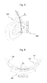
- FIG. 8 is a perspective view illustrating the structure of the cushion pad for head bands in accordance with the present invention.
- a cushion pad for head bands in accordance with the present invention includes, as exemplarily shown in FIGS. 1 to 8 , a pad unit 100 closely adhered to the back of a worker's head and an adjustment unit 200 to adjust the length of a head band.
- the present invention relates to a cushion pad for head bands which is installed at the rear part of a head band worn on a worker's head so as to support the back of the worker's head while adjusting the length of the head band
- the cushion pad for head bands includes the pad unit 100 having a concave spherical-shaped surface closely adhered to the back of the worker's head and provided with a first prop 110 extending from the center of the pad unit 100 to support the upper central region of the back of the worker's head and second props 120 extending from the center of the pad unit 100 to support both lower side regions of the back of the worker's head, and the adjustment unit 200 formed at the rear of the center of the pad unit 100 and provided with through holes formed at both sides thereof to receive both rear ends of the head band and a rotary lever installed at the rear of the middle between the through holes to pressurize and thus fix the head band.
- the pad unit 100 has a concave spherical-shaped surface closely adhered to the back of the worker's head and is provided with the first prop 110 extending from the center of the pad unit 100 to support the upper central region of the back of the worker's head and the second props 120 extending from the center of the pad unit 100 to support both lower side regions of the back of the worker's head.
- the pad unit 100 has a spherical surface closely adhered to the spherical surface of the back of the worker's head so as to conveniently and stably support the back of the worker's head, and is formed to have a tripod structure having the first prop 110 and the second props 120 so as to stably support the worker's head and to allow the worker to conveniently move his/her neck.
- a curved surface which is concave upwards for free movement of the neck, is formed between the second props 120 .
- the radius R 1 may be about 85 mm
- the radius R 2 may be about 120 mm.
- a curved surface for convenient neck movement is formed between the second props 120 of the pad unit 100 .
- a radius R 3 of the curved surface between the second props 120 of the pad unit 100 as seen from the bottom is 35 to 80 mm and a radius R 4 of the curved surface between the second props 120 of the pad unit 100 as seen from the front is 50 to 100 mm.
- the radius R 3 may be about 60 mm and the radius R 4 may be about 70 mm.
- a distance D 1 from the center of the pad unit 100 to the end of the first prop 110 of the pad unit 100 as seen from the front is 40 to 80 mm.
- the distance D 1 may be about 55 mm.
- a distance D 2 from the center of the pad unit 100 to the lower end of the pad unit 100 between the second props 120 is 15 to 50 mm
- a distance D 3 from the center of the pad unit 100 to the lower ends of the second props 120 is 30 to 70 mm.
- the distance D 2 may be about 40 mm
- the distance D 3 may be about 45 mm.
- the adjustment unit 200 is formed at the rear of the center of the pad unit 100 , and is provided with through holes 210 formed through both sides thereof to receive both rear ends of the head band and a rotary lever 220 installed at the rear of the middle between the through holes 210 to adjust the length of the head band. Therefore, after both rear ends of the head band are inserted into the through holes 210 and then the length of the head band is adjusted, the rotary lever 220 is rotated to pressurize the head band in the through holes 210 and thus fixes the adjusted length of the head band.
- a cushion pad for head bands in accordance with another embodiment of the present invention is formed by double injection molding using a hard material and a soft material.
- a pad unit 100 has a concave spherical-shaped surface closely adhered to the back of a worker's head, and an edge pressure part 150 including first and second props 110 and 120 extending from the center of the pad unit 100 to support the upper central region and both side regions of the back of the worker's head has both a pressurizing function and a cushioning function.
- the edge pressure part 150 formed of a soft material includes an end part having a small thickness and formed at the end thereof and a plurality of edge protrusions 160 formed at the center thereof so as to apply pressure.
- a hard center part 170 provided with a central groove formed at the center thereof and extending to the second props 120 supporting both sides of the back of the worker's head to support the second props 120 formed of a soft material is formed. Otherwise, air vent holes 180 to rapidly exhaust air therethrough without pressure applied thereto, when the cushion pad is worn on the worker's head, are formed through the surfaces of the second props 120 , and cause air to smoothly enter into and exit from the worker's head therethrough so that the wearing part of the worker's head within the cushion pad is dehumidified.
- the first and second props 110 and 120 having the above-described triangular structure of the pad unit 100 are formed to have the respective radii R 1 , R 2 , R 3 and R 4 . That is, the radius R 1 of the center of the spherical surface of the pad unit 100 in the leftward and rightward directions is 70 to 110 mm, the radius R 2 of the center of the spherical surface of the pad unit 100 in the upward and downward directions is 85 to 130 mm, the radius R 3 of a curved surface formed between the second props 120 for convenient neck movement as seen from the bottom is 35 to 80 mm and the radius R 4 of the curved surface as seen from the front is 50 to 100 mm.
- the cushion pad for head bands is selectively applied to a ski helmet, a bicycle helmet, a motorcycle helmet, virtual reality goggles, a safety helmet, an industrial helmet, a safety face shield and a welding helmet.
- the above-described cushion pad for head bands has an ergonomic structure and a minimized weight so as to be fixed to a worker's head.
- the cushion pad for head bands in accordance with the present invention is installed at the rear part of a head band of a welding mask so as to stably support the back of a worker's head while adjusting the length of the head band, thereby allowing a worker to more conveniently and stably wear the welding mask.
- a cushion pad for head bands in accordance with the present invention is installed at the rear part of a head band of a welding mask, etc. so as to stably support the back of a worker's head while adjusting the length of the head band, thereby allowing a worker to more conveniently and stably wear the welding mask, etc. Further, the cushion pad for head bands in accordance with the present invention stably supports and surrounds the lower part of the back of the worker's head so as not to be removed from the worker's head in spite of strong motion of the worker's head and may thus be conveniently used by the worker.
Landscapes
- Health & Medical Sciences (AREA)
- General Health & Medical Sciences (AREA)
- Life Sciences & Earth Sciences (AREA)
- Biomedical Technology (AREA)
- Heart & Thoracic Surgery (AREA)
- Vascular Medicine (AREA)
- Engineering & Computer Science (AREA)
- Animal Behavior & Ethology (AREA)
- Ophthalmology & Optometry (AREA)
- Public Health (AREA)
- Veterinary Medicine (AREA)
- Physical Education & Sports Medicine (AREA)
- Helmets And Other Head Coverings (AREA)
Abstract
A cushion pad for head bands, installed at the rear part of a head band worn on a worker's head so as to support the back of the worker's head while adjusting the length of the head band. The cushion pad includes a pad unit having a concave spherical-shaped surface closely adhered to the back of the worker's head and provided with a first prop and second props to support the upper central region and both lower side regions of the back of the worker's head, and an adjustment unit formed at the rear of the center of the pad unit and provided with through holes formed at both sides thereof to receive both rear ends of the head band and a rotary lever between the through holes to pressurize and fix the head band, thus allowing a worker to more conveniently and stably wear a welding mask.
Description
The present invention relates to an occipital triangular cushion pad for head bands which conveniently supports the back of a worker's head wearing a welding mask and is not easily removed from the worker's head.
In general, a welding mask includes a protective shield to protect worker's face and eyes and a head band to fix the protective shield to the worker's head.
As disclosed in Korean Utility Model Registration No. 0410449 (Publication Date: Mar. 9, 2006), a head band includes a side part fixed along the circumference of a worker's head, and an upper part extending from both sides of the side part to the top of the worker's head, and the rear region of the side part of the head band is cut so that the length of the side part is adjustable according to the circumference of the worker's head. Therefore, an adjustment unit to adjust the length of the head band and a cushion pad are formed at the rear part of the head band. The cushion pad has a function of solving inconvenience on the back of the worker's head caused by the adjustment unit and is stably adhered to the worker's head.
However, the cushion pad is formed to extend in the horizontal direction or to extend in the vertical direction and may not safely surround the back of the worker's head.
Further, the head band is easily removed from the worker's head and, if the worker bends his/her head back, the head band contacts the worker's neck and causes inconvenience.
Therefore, the present invention has been made in view of the above problems, and it is an object of the present invention to provide an ergonomic occipital triangular cushion pad for head bands which is installed at the rear part of a head band of a welding mask so as to adjust the length of the head band and to stably surround the back of a worker's head wearing the welding mask, and, particularly, supports the shape of the lower part of the worker's head so as to prevent the head band from being removed from the worker's head and matches the horizontal and vertical sizes of the back of the worker's head so as to be stably mounted on the back of the worker's head.
It is another object of the present invention to provide an occipital triangular cushion pad for head bands which ergonomically surrounds the back of a worker's head so as to minimize pressure applied to the worker's head by a head band, and generates stopping power between the worker's head and the head band and a soft contact surface therebetween.
It is another object of the present invention to provide an occipital triangular cushion pad for head bands which is formed by double injection molding using a hard material and a soft material, such as hard urethane and silicone, so as to prevent a head band from sliding on hair.
It is yet another object of the present invention to provide an occipital triangular cushion pad for head bands which is selectively applied to a ski helmet, a bicycle helmet, a motorcycle helmet, virtual reality goggles, a safety helmet, an industrial helmet, a safety face shield and a welding helmet so as to be conveniently worn by a worker.
In accordance with an aspect of the present invention, the above and other objects can be accomplished by the provision of a cushion pad for head bands, installed at the rear part of a head band worn on a worker's head so as to support the back of the worker's head while adjusting the length of the head band, the cushion pad for head bands including a pad unit having a concave spherical-shaped surface closely adhered to the back of the worker's head and provided with a first prop extending from the center of the pad unit to support the upper central region of the back of the worker's head and second props extending from the center of the pad unit to support both lower side regions of the back of the worker's head, and an adjustment unit formed at the rear of the center of the pad unit and provided with through holes formed at both sides thereof to receive both rear ends of the head band and a rotary lever installed at the rear of the middle between the through holes to pressurize and thus fix the head band.
A radius R1 of the center of the spherical surface of the pad unit in the leftward and rightward directions may be 70 to 110 mm, and a radius R2 of the center of the spherical surface of the pad unit in the upward and downward directions may be 85 to 130 mm.
A radius R3 of a curved surface formed between the second props as seen from the bottom may be 35 to 80 mm, and a radius R4 of the curved surface as seen from the front may be 50 to 100 mm.
A distance D1 from the center of the pad unit to the end of the first prop as seen from the front may be 40 to 80 mm, a distance D2 from the center of the pad unit to the lower end of the pad unit between the second props may be 15 to 50 mm, and a distance D3 from the center of the pad unit to the lower ends of the second props may be 30 to 70 mm.
The above and other objects, features and other advantages of the present invention will be more clearly understood from the following detailed description taken in conjunction with the accompanying drawings, in which:
Now, preferred embodiments in accordance with the present invention will be described in detail with reference to the annexed drawings. Terms used in the following description or the claims are not interpreted as having conventional or dictionary meanings and, in order to describe the invention in the best mode by the inventor(s), the definitions of these terms should be determined based on the whole content of this specification.
Therefore, the embodiments stated in the specification and elements illustrated in the drawings have been made only for a better understanding of the present invention and those skilled in the art will appreciate that various modifications, additions, and substitutions to the specific elements are possible, without departing from the scope and spirit of the invention as disclosed in the accompanying claims.
A cushion pad for head bands in accordance with the present invention includes, as exemplarily shown in FIGS. 1 to 8 , a pad unit 100 closely adhered to the back of a worker's head and an adjustment unit 200 to adjust the length of a head band.
The present invention relates to a cushion pad for head bands which is installed at the rear part of a head band worn on a worker's head so as to support the back of the worker's head while adjusting the length of the head band, and the cushion pad for head bands includes the pad unit 100 having a concave spherical-shaped surface closely adhered to the back of the worker's head and provided with a first prop 110 extending from the center of the pad unit 100 to support the upper central region of the back of the worker's head and second props 120 extending from the center of the pad unit 100 to support both lower side regions of the back of the worker's head, and the adjustment unit 200 formed at the rear of the center of the pad unit 100 and provided with through holes formed at both sides thereof to receive both rear ends of the head band and a rotary lever installed at the rear of the middle between the through holes to pressurize and thus fix the head band.
The pad unit 100 has a concave spherical-shaped surface closely adhered to the back of the worker's head and is provided with the first prop 110 extending from the center of the pad unit 100 to support the upper central region of the back of the worker's head and the second props 120 extending from the center of the pad unit 100 to support both lower side regions of the back of the worker's head. That is, the pad unit 100 has a spherical surface closely adhered to the spherical surface of the back of the worker's head so as to conveniently and stably support the back of the worker's head, and is formed to have a tripod structure having the first prop 110 and the second props 120 so as to stably support the worker's head and to allow the worker to conveniently move his/her neck. Particularly, a curved surface, which is concave upwards for free movement of the neck, is formed between the second props 120.
In accordance with one embodiment of the present invention, a radius R1 of the center of the spherical surface of the pad unit 100 in the leftward and rightward directions of 70 to 110 mm and a radius R2 of the center of the spherical surface of the pad unit 100 in the upward and downward directions of 85 to 130 mm. Here, the radius R1 may be about 85 mm, and the radius R2 may be about 120 mm.
A curved surface for convenient neck movement is formed between the second props 120 of the pad unit 100. A radius R3 of the curved surface between the second props 120 of the pad unit 100 as seen from the bottom is 35 to 80 mm and a radius R4 of the curved surface between the second props 120 of the pad unit 100 as seen from the front is 50 to 100 mm. Here, the radius R3 may be about 60 mm and the radius R4 may be about 70 mm.
A distance D1 from the center of the pad unit 100 to the end of the first prop 110 of the pad unit 100 as seen from the front is 40 to 80 mm. Here, the distance D1 may be about 55 mm.
A distance D2 from the center of the pad unit 100 to the lower end of the pad unit 100 between the second props 120 is 15 to 50 mm, and a distance D3 from the center of the pad unit 100 to the lower ends of the second props 120 is 30 to 70 mm. Here, the distance D2 may be about 40 mm, and the distance D3 may be about 45 mm.
The adjustment unit 200 is formed at the rear of the center of the pad unit 100, and is provided with through holes 210 formed through both sides thereof to receive both rear ends of the head band and a rotary lever 220 installed at the rear of the middle between the through holes 210 to adjust the length of the head band. Therefore, after both rear ends of the head band are inserted into the through holes 210 and then the length of the head band is adjusted, the rotary lever 220 is rotated to pressurize the head band in the through holes 210 and thus fixes the adjusted length of the head band.
In order to prevent a head band from sliding on hair, a cushion pad for head bands in accordance with another embodiment of the present invention is formed by double injection molding using a hard material and a soft material.
Further, a pad unit 100 has a concave spherical-shaped surface closely adhered to the back of a worker's head, and an edge pressure part 150 including first and second props 110 and 120 extending from the center of the pad unit 100 to support the upper central region and both side regions of the back of the worker's head has both a pressurizing function and a cushioning function.
The edge pressure part 150 formed of a soft material includes an end part having a small thickness and formed at the end thereof and a plurality of edge protrusions 160 formed at the center thereof so as to apply pressure. A hard center part 170 provided with a central groove formed at the center thereof and extending to the second props 120 supporting both sides of the back of the worker's head to support the second props 120 formed of a soft material is formed. Otherwise, air vent holes 180 to rapidly exhaust air therethrough without pressure applied thereto, when the cushion pad is worn on the worker's head, are formed through the surfaces of the second props 120, and cause air to smoothly enter into and exit from the worker's head therethrough so that the wearing part of the worker's head within the cushion pad is dehumidified.
The first and second props 110 and 120 having the above-described triangular structure of the pad unit 100 are formed to have the respective radii R1, R2, R3 and R4. That is, the radius R1 of the center of the spherical surface of the pad unit 100 in the leftward and rightward directions is 70 to 110 mm, the radius R2 of the center of the spherical surface of the pad unit 100 in the upward and downward directions is 85 to 130 mm, the radius R3 of a curved surface formed between the second props 120 for convenient neck movement as seen from the bottom is 35 to 80 mm and the radius R4 of the curved surface as seen from the front is 50 to 100 mm.
The cushion pad for head bands is selectively applied to a ski helmet, a bicycle helmet, a motorcycle helmet, virtual reality goggles, a safety helmet, an industrial helmet, a safety face shield and a welding helmet.
The above-described cushion pad for head bands has an ergonomic structure and a minimized weight so as to be fixed to a worker's head.
As described above, the cushion pad for head bands in accordance with the present invention is installed at the rear part of a head band of a welding mask so as to stably support the back of a worker's head while adjusting the length of the head band, thereby allowing a worker to more conveniently and stably wear the welding mask.
As apparent from the above description, a cushion pad for head bands in accordance with the present invention is installed at the rear part of a head band of a welding mask, etc. so as to stably support the back of a worker's head while adjusting the length of the head band, thereby allowing a worker to more conveniently and stably wear the welding mask, etc. Further, the cushion pad for head bands in accordance with the present invention stably supports and surrounds the lower part of the back of the worker's head so as not to be removed from the worker's head in spite of strong motion of the worker's head and may thus be conveniently used by the worker.
Although the preferred embodiments of the present invention have been disclosed for illustrative purposes, those skilled in the art will appreciate that various modifications, additions and substitutions are possible, without departing from the scope and spirit of the invention as disclosed in the accompanying claims.
Claims (16)
1. A cushion pad for head bands, installed at the rear part of a head band worn on a worker's head so as to support the back of the worker's head while adjusting the length of the head band, the cushion pad for head bands including:
a pad unit having a concave spherical-shaped surface closely adhered to the back of the worker's head and provided with a first prop extending from the center of the pad unit to support the upper central region of the back of the worker's head and second props extending from the center of the pad unit to support both lower side regions of the back of the worker's head; and
an adjustment unit formed at the rear of the center of the pad unit and provided with through holes formed at both sides thereof to receive both rear ends of the head band and a rotary lever installed at the rear of the middle between the through holes to pressurize and thus fix the head band.
2. The cushion pad for head bands according to claim 1 , wherein a radius R1 of the center of the spherical surface of the pad unit in the leftward and rightward directions is 70 to 110 mm, and a radius R2 of the center of the spherical surface of the pad unit in the upward and downward directions is 85 to 130 mm.
3. The cushion pad for head bands according to claim 1 , wherein a radius R3 of a curved surface formed between the second props as seen from the bottom is 35 to 80 mm, and a radius R4 of the curved surface as seen from the front is 50 to 100 mm.
4. The cushion pad for head bands according to claim 1 , wherein a distance D1 from the center of the pad unit to the end of the first prop as seen from the front is 40 to 80 mm, a distance D2 from the center of the pad unit to the lower end of the pad unit between the second props is 15 to 50 mm, and a distance D3 from the center of the pad unit to the lower ends of the second props is 30 to 70 mm.
5. The cushion pad for head bands according to claim 1 , wherein the pad unit is formed by double injection molding using a hard material and a soft material so as to prevent the head band from sliding on hair.
6. The cushion pad for head bands according to claim 1 , wherein the pad unit includes an edge pressure part formed of a soft material and a hard center part, wherein:
the edge pressure part includes an end part having a small thickness and a plurality of edge protrusions formed at the center of the edge pressure part so as to apply pressure thereto; and
the hard center part is provided with a central groove formed at the center thereof and extending to the second props supporting both sides of the back of the worker's head to support the second props formed of the soft material.
7. The cushion pad for head bands according to claim 1 , wherein air vent holes to rapidly exhaust air therethrough without pressure applied thereto are formed through the surfaces of the second props, and cause air to smoothly enter into and exit from the worker's head therethrough so that the wearing part of the worker's head within the cushion pad is dehumidified.
8. The cushion pad for head bands according to claim 1 , wherein the first and second props having a triangular structure of the pad unit are formed to have respective radii R1, R2, R3 and R4,
wherein the radius R1 of the center of the spherical surface of the pad unit in the leftward and rightward directions is 70 to 110 mm, the radius R2 of the center of the spherical surface of the pad unit the upward and downward directions is 85 to 130 mm, the radius R3 of a curved surface, formed between the second props of the pad unit for convenient neck movement, as seen from the bottom is 35 to 80 mm and the radius R4 of the curved surface as seen from the front is 50 to 100 mm.
9. The cushion pad for head bands according to claim 1 , being selectively applied to a ski helmet, a bicycle helmet, a motorcycle helmet, virtual reality goggles, a safety helmet, an industrial helmet, a safety face shield and a welding helmet.
10. The cushion pad for head bands according to claim 1 , wherein the first prop extends vertically from the center of the pad unit to support the upper central region of the back of the worker's head.
11. The cushion pad for head bands according to claim 10 , wherein the cushion pad matches horizontal and vertical sizes of the back of the worker's head.
12. The cushion pad for head bands according to claim 11 , wherein the cushion pad ergonomically surrounds the back of the worker's head.
13. The cushion pad for head bands according to claim 12 , wherein the cushion pad surrounds the lower part of the back of the worker's head.
14. The cushion pad for head bands according to claim 1 , wherein:
a radius R1 of the center of the spherical surface of the pad unit in the leftward and rightward directions is 70 to 110 mm;
a radius R2 of the center of the spherical surface of the pad unit in the upward and downward directions is 85 to 130 mm;
a radius R3 of a curved surface formed between the second props as seen from the bottom is 35 to 80 mm; and
a radius R4 of the curved surface as seen from the front is 50 to 100 mm.
15. The cushion pad for head bands according to claim 14 , wherein:
a distance D1 from the center of the pad unit to the end of the first prop as seen from the front is 40 to 80 mm;
a distance D2 from the center of the pad unit to the lower end of the pad unit between the second props is 15 to 50 mm; and
a distance D3 from the center of the pad unit to the lower ends of the second props is 30 to 70 mm.
16. The cushion pad for head bands according to claim 15 , wherein the first and second props have a triangular structure.
Priority Applications (1)
| Application Number | Priority Date | Filing Date | Title |
|---|---|---|---|
| US15/392,358 US10149509B2 (en) | 2016-12-28 | 2016-12-28 | Ergonomic occipital triangular cushion pad for head bands |
Applications Claiming Priority (1)
| Application Number | Priority Date | Filing Date | Title |
|---|---|---|---|
| US15/392,358 US10149509B2 (en) | 2016-12-28 | 2016-12-28 | Ergonomic occipital triangular cushion pad for head bands |
Publications (2)
| Publication Number | Publication Date |
|---|---|
| US20180177259A1 US20180177259A1 (en) | 2018-06-28 |
| US10149509B2 true US10149509B2 (en) | 2018-12-11 |
Family
ID=62624898
Family Applications (1)
| Application Number | Title | Priority Date | Filing Date |
|---|---|---|---|
| US15/392,358 Active 2037-04-15 US10149509B2 (en) | 2016-12-28 | 2016-12-28 | Ergonomic occipital triangular cushion pad for head bands |
Country Status (1)
| Country | Link |
|---|---|
| US (1) | US10149509B2 (en) |
Cited By (1)
| Publication number | Priority date | Publication date | Assignee | Title |
|---|---|---|---|---|
| US20200390182A1 (en) * | 2019-06-14 | 2020-12-17 | Otos Wing.Co., Ltd. | Head band |
Families Citing this family (1)
| Publication number | Priority date | Publication date | Assignee | Title |
|---|---|---|---|---|
| US10656670B2 (en) * | 2018-06-04 | 2020-05-19 | Htc Corporation | Head-mounted display device |
Citations (25)
| Publication number | Priority date | Publication date | Assignee | Title |
|---|---|---|---|---|
| US20050138719A1 (en) * | 2003-04-29 | 2005-06-30 | Huh Moon Y. | Cushion pad structure for headband |
| KR200410449Y1 (en) | 2005-12-07 | 2006-03-09 | 오토스테크 주식회사 | Head band device for welding mask |
| US20060080761A1 (en) * | 2004-10-20 | 2006-04-20 | Otos Tech Co., Ltd. | Multifunctional protection rack for safety helmet |
| US20060185052A1 (en) * | 2005-02-09 | 2006-08-24 | Otos Tech Co., Ltd. | Welding helmet having cartridge coupling structure |
| US20070079417A1 (en) * | 2005-10-07 | 2007-04-12 | Huh Moon Y | Front surface opened welding mask |
| US20070080621A1 (en) * | 2005-10-07 | 2007-04-12 | Huh Moon Y | Connecting structure of LCD shielding screen for welding mask |
| US20070131845A1 (en) * | 2005-12-14 | 2007-06-14 | Huh Moon Y | Apparatus for detecting welding light and protecting eyes from glare and method for controlling the same |
| US20070152132A1 (en) * | 2005-12-30 | 2007-07-05 | Moon Young Huh | Apparatus for detecting electromagnetic wave and protecting eyes from glare |
| US20070220649A1 (en) * | 2006-03-24 | 2007-09-27 | Otos Tech Co., Ltd. | Multi-function face protector |
| US20070250986A1 (en) * | 2006-04-28 | 2007-11-01 | Ako Kunststoffe Alfred Kolb Gmbh | Head strap |
| US20080120752A1 (en) * | 2004-03-26 | 2008-05-29 | Moon Young Huh | Dazzle Prevention Device Having Electro Magnetic Wave Detection Function |
| US20090000001A1 (en) * | 2007-06-27 | 2009-01-01 | Otos Tech Co., Ltd. | Welding helmet with protection cover for cartridge |
| US20090089908A1 (en) * | 2007-10-09 | 2009-04-09 | Otos Tech Co., Ltd. | Air supplying device for welding mask |
| US20090320187A1 (en) * | 2008-06-26 | 2009-12-31 | Zedel | Protective helmet for hair worn in a pony tail |
| US20100095438A1 (en) * | 2008-10-21 | 2010-04-22 | Moelker Michael G | Headband with pivotal pad |
| US20100132086A1 (en) * | 2008-12-03 | 2010-06-03 | Otos Tech Co., Ltd. | Welding mask that can control lcd shielding goggle without taking off |
| US20110010815A1 (en) * | 2009-07-15 | 2011-01-20 | Otos Tech Co., Ltd. | Welding helmet including anti-blinding device to selectively and conveniently control welding operation and grinding operation |
| US20110289659A1 (en) * | 2010-05-27 | 2011-12-01 | Zedel | Safety helmet with improved adjustment |
| US20110315734A1 (en) * | 2010-06-29 | 2011-12-29 | Otos Tech Co., Ltd. | Belt hanger for helmets |
| US20120144567A1 (en) * | 2010-12-13 | 2012-06-14 | Otos Wing Co., Ltd. | Hinge coupling structure for welding mask, face shield and safety helmet |
| US20120144565A1 (en) * | 2010-12-13 | 2012-06-14 | Otos Wing Co., Ltd. | Head band |
| US20130111648A1 (en) * | 2011-11-04 | 2013-05-09 | Otos Wing Co., Ltd. | Cushion for headband |
| US20130111653A1 (en) * | 2011-11-04 | 2013-05-09 | Otos Wing Co., Ltd. | Air cushion for attaching headband of welding mask |
| US20150074877A1 (en) * | 2013-09-16 | 2015-03-19 | Otos Wing Co., Ltd. | Coupling structure of replaceable visor hinge for headband |
| US9907348B2 (en) * | 2015-03-13 | 2018-03-06 | Otos Wing Co., Ltd. | Functional headband having integral cushion band |
-
2016
- 2016-12-28 US US15/392,358 patent/US10149509B2/en active Active
Patent Citations (25)
| Publication number | Priority date | Publication date | Assignee | Title |
|---|---|---|---|---|
| US20050138719A1 (en) * | 2003-04-29 | 2005-06-30 | Huh Moon Y. | Cushion pad structure for headband |
| US20080120752A1 (en) * | 2004-03-26 | 2008-05-29 | Moon Young Huh | Dazzle Prevention Device Having Electro Magnetic Wave Detection Function |
| US20060080761A1 (en) * | 2004-10-20 | 2006-04-20 | Otos Tech Co., Ltd. | Multifunctional protection rack for safety helmet |
| US20060185052A1 (en) * | 2005-02-09 | 2006-08-24 | Otos Tech Co., Ltd. | Welding helmet having cartridge coupling structure |
| US20070079417A1 (en) * | 2005-10-07 | 2007-04-12 | Huh Moon Y | Front surface opened welding mask |
| US20070080621A1 (en) * | 2005-10-07 | 2007-04-12 | Huh Moon Y | Connecting structure of LCD shielding screen for welding mask |
| KR200410449Y1 (en) | 2005-12-07 | 2006-03-09 | 오토스테크 주식회사 | Head band device for welding mask |
| US20070131845A1 (en) * | 2005-12-14 | 2007-06-14 | Huh Moon Y | Apparatus for detecting welding light and protecting eyes from glare and method for controlling the same |
| US20070152132A1 (en) * | 2005-12-30 | 2007-07-05 | Moon Young Huh | Apparatus for detecting electromagnetic wave and protecting eyes from glare |
| US20070220649A1 (en) * | 2006-03-24 | 2007-09-27 | Otos Tech Co., Ltd. | Multi-function face protector |
| US20070250986A1 (en) * | 2006-04-28 | 2007-11-01 | Ako Kunststoffe Alfred Kolb Gmbh | Head strap |
| US20090000001A1 (en) * | 2007-06-27 | 2009-01-01 | Otos Tech Co., Ltd. | Welding helmet with protection cover for cartridge |
| US20090089908A1 (en) * | 2007-10-09 | 2009-04-09 | Otos Tech Co., Ltd. | Air supplying device for welding mask |
| US20090320187A1 (en) * | 2008-06-26 | 2009-12-31 | Zedel | Protective helmet for hair worn in a pony tail |
| US20100095438A1 (en) * | 2008-10-21 | 2010-04-22 | Moelker Michael G | Headband with pivotal pad |
| US20100132086A1 (en) * | 2008-12-03 | 2010-06-03 | Otos Tech Co., Ltd. | Welding mask that can control lcd shielding goggle without taking off |
| US20110010815A1 (en) * | 2009-07-15 | 2011-01-20 | Otos Tech Co., Ltd. | Welding helmet including anti-blinding device to selectively and conveniently control welding operation and grinding operation |
| US20110289659A1 (en) * | 2010-05-27 | 2011-12-01 | Zedel | Safety helmet with improved adjustment |
| US20110315734A1 (en) * | 2010-06-29 | 2011-12-29 | Otos Tech Co., Ltd. | Belt hanger for helmets |
| US20120144567A1 (en) * | 2010-12-13 | 2012-06-14 | Otos Wing Co., Ltd. | Hinge coupling structure for welding mask, face shield and safety helmet |
| US20120144565A1 (en) * | 2010-12-13 | 2012-06-14 | Otos Wing Co., Ltd. | Head band |
| US20130111648A1 (en) * | 2011-11-04 | 2013-05-09 | Otos Wing Co., Ltd. | Cushion for headband |
| US20130111653A1 (en) * | 2011-11-04 | 2013-05-09 | Otos Wing Co., Ltd. | Air cushion for attaching headband of welding mask |
| US20150074877A1 (en) * | 2013-09-16 | 2015-03-19 | Otos Wing Co., Ltd. | Coupling structure of replaceable visor hinge for headband |
| US9907348B2 (en) * | 2015-03-13 | 2018-03-06 | Otos Wing Co., Ltd. | Functional headband having integral cushion band |
Cited By (2)
| Publication number | Priority date | Publication date | Assignee | Title |
|---|---|---|---|---|
| US20200390182A1 (en) * | 2019-06-14 | 2020-12-17 | Otos Wing.Co., Ltd. | Head band |
| US11771168B2 (en) * | 2019-06-14 | 2023-10-03 | Otos Wing.Co., Ltd. | Head band |
Also Published As
| Publication number | Publication date |
|---|---|
| US20180177259A1 (en) | 2018-06-28 |
Similar Documents
| Publication | Publication Date | Title |
|---|---|---|
| US9907348B2 (en) | Functional headband having integral cushion band | |
| US11771168B2 (en) | Head band | |
| US10016008B2 (en) | Headgear for protective headwear | |
| CN109752849B (en) | Head-mounted display device | |
| US7430763B1 (en) | Visor mounted face protector | |
| US20170150770A1 (en) | Headband having integrated functional cushion case | |
| US20070016998A1 (en) | Safety hard hat and face shield assembly | |
| JP2017509809A (en) | Adaptive fit helmet and method for fitting a helmet to a customer's head | |
| KR20100092432A (en) | Head suspension headband | |
| US20160158064A1 (en) | Mask with a comfort element | |
| US11042042B2 (en) | Flexible temples for glasses frames | |
| CN113576089B (en) | Protective helmet with intermediate piece for changing the centre of gravity and assembly | |
| US10149509B2 (en) | Ergonomic occipital triangular cushion pad for head bands | |
| EP3667398A1 (en) | Head mounted device | |
| KR101961435B1 (en) | Triangular cushion pad for headband | |
| GB2558317A (en) | Ergonomic occipital triangular cushion pad for head bands | |
| KR20200143303A (en) | Head band | |
| CN107361444B (en) | Ergonomic structural headband rear triangular cushion pad | |
| JP2016213638A (en) | Head-mounted display device | |
| US20210191148A1 (en) | Eyewear attachment and eyewear assembly | |
| KR102296424B1 (en) | Headrest band for hard hat and hard hat with the same | |
| JP6118770B2 (en) | goggles | |
| CN213908637U (en) | Head-wearing type face mask | |
| KR102140899B1 (en) | safety helmet having face cover | |
| TWI748512B (en) | Head mounted display |
Legal Events
| Date | Code | Title | Description |
|---|---|---|---|
| AS | Assignment |
Owner name: OTOS WING CO., LTD., KOREA, REPUBLIC OF Free format text: ASSIGNMENT OF ASSIGNORS INTEREST;ASSIGNOR:HUH, MOON YOUNG;REEL/FRAME:040785/0829 Effective date: 20161226 |
|
| STCF | Information on status: patent grant |
Free format text: PATENTED CASE |
|
| MAFP | Maintenance fee payment |
Free format text: PAYMENT OF MAINTENANCE FEE, 4TH YR, SMALL ENTITY (ORIGINAL EVENT CODE: M2551); ENTITY STATUS OF PATENT OWNER: SMALL ENTITY Year of fee payment: 4 |