US101403A - Improvement sn hose-couplings - Google Patents
Improvement sn hose-couplings Download PDFInfo
- Publication number
- US101403A US101403A US101403DA US101403A US 101403 A US101403 A US 101403A US 101403D A US101403D A US 101403DA US 101403 A US101403 A US 101403A
- Authority
- US
- United States
- Prior art keywords
- hose
- couplings
- tube
- rings
- parts
- Prior art date
- Legal status (The legal status is an assumption and is not a legal conclusion. Google has not performed a legal analysis and makes no representation as to the accuracy of the status listed.)
- Expired - Lifetime
Links
- 238000010168 coupling process Methods 0.000 title description 12
- 238000005859 coupling reaction Methods 0.000 title description 12
- 230000008878 coupling Effects 0.000 description 10
- 230000033001 locomotion Effects 0.000 description 5
- 239000002184 metal Substances 0.000 description 4
- 239000007789 gas Substances 0.000 description 3
- XLYOFNOQVPJJNP-UHFFFAOYSA-N water Substances O XLYOFNOQVPJJNP-UHFFFAOYSA-N 0.000 description 3
- 239000012530 fluid Substances 0.000 description 2
- 239000000463 material Substances 0.000 description 2
- 238000000034 method Methods 0.000 description 2
- 230000005540 biological transmission Effects 0.000 description 1
- 230000006835 compression Effects 0.000 description 1
- 238000007906 compression Methods 0.000 description 1
- 238000010276 construction Methods 0.000 description 1
- 238000012856 packing Methods 0.000 description 1
- 238000011084 recovery Methods 0.000 description 1
- 230000000717 retained effect Effects 0.000 description 1
Images

Classifications
-
- F—MECHANICAL ENGINEERING; LIGHTING; HEATING; WEAPONS; BLASTING
- F16—ENGINEERING ELEMENTS AND UNITS; GENERAL MEASURES FOR PRODUCING AND MAINTAINING EFFECTIVE FUNCTIONING OF MACHINES OR INSTALLATIONS; THERMAL INSULATION IN GENERAL
- F16L—PIPES; JOINTS OR FITTINGS FOR PIPES; SUPPORTS FOR PIPES, CABLES OR PROTECTIVE TUBING; MEANS FOR THERMAL INSULATION IN GENERAL
- F16L25/00—Construction or details of pipe joints not provided for in, or of interest apart from, groups F16L13/00 - F16L23/00
- F16L25/06—Construction or details of pipe joints not provided for in, or of interest apart from, groups F16L13/00 - F16L23/00 comprising radial locking means
- F16L25/08—Construction or details of pipe joints not provided for in, or of interest apart from, groups F16L13/00 - F16L23/00 comprising radial locking means in the form of screws, nails or the like
-
- Y—GENERAL TAGGING OF NEW TECHNOLOGICAL DEVELOPMENTS; GENERAL TAGGING OF CROSS-SECTIONAL TECHNOLOGIES SPANNING OVER SEVERAL SECTIONS OF THE IPC; TECHNICAL SUBJECTS COVERED BY FORMER USPC CROSS-REFERENCE ART COLLECTIONS [XRACs] AND DIGESTS
- Y10—TECHNICAL SUBJECTS COVERED BY FORMER USPC
- Y10S—TECHNICAL SUBJECTS COVERED BY FORMER USPC CROSS-REFERENCE ART COLLECTIONS [XRACs] AND DIGESTS
- Y10S285/00—Pipe joints or couplings
- Y10S285/91—Gaskets
Definitions
- This invention relates to couplings for connecting together different lengths of bose or pipe of any kind intended to be used for the transmission of fluids or gases.
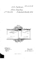
- Figure l shows a plan view of the end of one or either of the interlocking parts at the plane of junction.
- Fig. 8 shows a View of a longitudinal section through the middle of the coupling.
- Fig. 2 shows the saine view of any two of the portions of the coupling ready to be connected and the operation of the device for preventing the escape of the iiuids or gas.
- a A is a tube or pipe of proper size, and of any suitable material, formed, when hose is to be attached, with grooves c a around thatpart over which the hose Vis to be slipped and fastenedin the ordinary manner. rIhe end of this pipe or tube, or the tube-pipe or hose itself, may be used directly with proper device, which is to be connected with an end of another, is turned down or rabbeted, as shown at b, so as to form a seat, beveled or parallel, for the reception of portion of one end of a tube or pipe, of rubber or other equivalent material, which is intended to be secured thereupon. The surface of this seat may be roughened or ragged, for the better security against slipping oft' of this rubber tube.
- the remaining portion of the rubber ring so long as not operated upon by any expansive force, as that of a current of water, retaining as much as possible its original diameter, will form an annular curtain or perforated diaphragm, b, over and covering aportion of the orifice of the metal tube from the circn inference inward toward the center to the extent ofthe difference ofthe diameter of the two tubes.
- e is they beveled recess of the seat, and f that of the projecting lip, the other part showing only the corresponding beveled recess of the seat on the opposite section of the coupling.
- the ends of the semicircular lips may also be beveled so as to interlock.
- each of the rings B B moves a covering ring, C, carried forward by threads of a screw cut on its interior surface and on the exterior surface of the ring B.
- These outer rings are so formed and adj usted that they may be screwed forward so as to meet over the center of the lapping parts of the coupling, or either may cover the joint entirely; but it is deemed better to provide two. They may be suitably milled on the outersur face to afford a better hold for thehand,which ordinarily will be sufficient for the purpose of screwing them up, or they may be provided witha beveled mortise on the rear edge or elsewhere, or any other suitable device which does not project to receive a proper instrument for turning ⁇ them if the force of the hand is not sufficient.
- any two will iit each other however the hose may be reversed, so that there can be no failure to couple or necessity for turning the sections of hose, and, as the flaps or curtains cover equally well in either direction,
- the hose-coupling formedto lock by side movement when the parts are so constructed that any two may t together, substantially as set forth.
Landscapes
- Engineering & Computer Science (AREA)
- General Engineering & Computer Science (AREA)
- Mechanical Engineering (AREA)
- Fire-Extinguishing By Fire Departments, And Fire-Extinguishing Equipment And Control Thereof (AREA)
Description
` UNnrED STATES PATENT OFFICE.
CHARLES H. GUSHMAN, OF ALEXANDRIA, VIRGINIA.
IMPROVEMENT lN HOSE-COUPLINGS.
Specification forming part of' Leiters Patent No. l0li,f103,daied March 2', w70.
T0 all whom it may concern:
Be it known that I, CHARLES H. Cosi-DIAN, ofAleXandria, in the county of Alexandria and State of Virginia, have invented a new and useful Improvement in Hose Couplings; and I do hereby declare that the following is a full and exact description of the same, reference being had to the accompanying drawings, and to the letters of reference marked thereon.
This invention relates to couplings for connecting together different lengths of bose or pipe of any kind intended to be used for the transmission of fluids or gases.
It consists of certain improvements in the structure of and in the method of connecting and securing together the interlocking parts of such couplings, and in preventing the escape at the junction thereof of the iiuids or gases while being transmitted through thehose or pipe and coupling, all as hereinafter fully set forth, and as shown in drawings annexed and forming a part of this specification.
In the drawings, Figure l shows a plan view of the end of one or either of the interlocking parts at the plane of junction. Fig. 8 shows a View of a longitudinal section through the middle of the coupling. Fig. 2 shows the saine view of any two of the portions of the coupling ready to be connected and the operation of the device for preventing the escape of the iiuids or gas.
The same letters and characters refer to identical parts in the several drawings.
A A is a tube or pipe of proper size, and of any suitable material, formed, when hose is to be attached, with grooves c a around thatpart over which the hose Vis to be slipped and fastenedin the ordinary manner. rIhe end of this pipe or tube, or the tube-pipe or hose itself, may be used directly with proper device, which is to be connected with an end of another, is turned down or rabbeted, as shown at b, so as to form a seat, beveled or parallel, for the reception of portion of one end of a tube or pipe, of rubber or other equivalent material, which is intended to be secured thereupon. The surface of this seat may be roughened or ragged, for the better security against slipping oft' of this rubber tube. One end of a rubber tube, b', of proper length and thickness, and of a diameter or circumference less than the interior one of the metallic tube, is stretchedand slipped over this seat, as shown, shrinking thereupon, and being further retainedin place, if necessary, by a wire or other fastening wound around it. The remaining portion of the rubber ring, so long as not operated upon by any expansive force, as that of a current of water, retaining as much as possible its original diameter, will form an annular curtain or perforated diaphragm, b, over and covering aportion of the orifice of the metal tube from the circn inference inward toward the center to the extent ofthe difference ofthe diameter of the two tubes. It is, however, free to be expanded in either direction by any passing current of sufficient force. Over this and a portion of the metal tube a band or ring, B, fits closely, and is retained in place by screws or other equivalent means. Thisband, with its duplicate upon another section of pipe or hose, forms the means of connection between the two. Each is formed with a projecting lip, c c, extending around half its circumference, and a seat, dd, occupying the other half of the circumference ofthe end ofthe rings. These rings are pushed so far upon the metal tube as to leave only the lip of the ring projecting beyond the end of the tube, so that the rubber rings covering the ends of opposite tubes are slightly compressed in bringing them together.
rlhe parts are so fitted that, `when brought together, the lip of each shall t into the seat of the other sufficiently close to produce a slight compression of the rubber tubes, as above mentioned, for which purpose, and also to allow for any battering or other slight change of original form, these lips and seats are moreover recessed in opposite direction and in beveled form, as shown in the drawings, the structure being such that the lips lock upon the seats and the seats into the lips by a lateral or transverse movement, and must be separated in the same manner.
In the drawing, e is they beveled recess of the seat, and f that of the projecting lip, the other part showing only the corresponding beveled recess of the seat on the opposite section of the coupling. The ends of the semicircular lips may also be beveled so as to interlock.
Over each of the rings B B moves a covering ring, C, carried forward by threads of a screw cut on its interior surface and on the exterior surface of the ring B. These outer rings are so formed and adj usted that they may be screwed forward so as to meet over the center of the lapping parts of the coupling, or either may cover the joint entirely; but it is deemed better to provide two. They may be suitably milled on the outersur face to afford a better hold for thehand,which ordinarily will be sufficient for the purpose of screwing them up, or they may be provided witha beveled mortise on the rear edge or elsewhere, or any other suitable device which does not project to receive a proper instrument for turning` them if the force of the hand is not sufficient.
Having thus explained the construction of this coupling, its method of connecting and its general operation may be described, as follows: The ,contiguous ends or interlocking parts of different sections being brought together, they are fitted to each other by a lateral or transverse movement, and the lip on each is placed on the seat of the other, causing the curtains or diaphragms to be brought into contact side by side and slightly pressing each other. The outer rings, C C, are then moved forward to cover the lips, or either of them to cover both, Fig. 3, and prevent any lateral movement ofthe parts which are th us securely locked together. The water or other fluid being now forced through the continuous tube thus formed, in either direction, coming in contact with the rubber curtains, forces them to eX- pand into atube-shape in the direction of its motion, so that the foremost one is turned back upon the interior surface of its own pipe or tube of metal, and the rear one is carried over and across the junction of the two tubes and firmly pressed upon the foremost one, forming a self-adjusting packing, which operates to prevent any leakage at the joint just in proportion to the pressure of the water upon its surface over that joint, so that the greater the pressure of the current flowing through the hose, and consequently the greater the tendency to leakage or escape, the more closely will the rubber flap or curtain be pressed over the junction of the two parts, and thus all leakage or escape be prevented.
The parts on each end being also counterparts, any two will iit each other however the hose may be reversed, so that there can be no failure to couple or necessity for turning the sections of hose, and, as the flaps or curtains cover equally well in either direction,
nection of the thread should be lost, and time expended in its recovery, or risk incurred of its mutilation, as is the case with couplings now in use.
Ido not confine myself to the precise forms shown, but,
Having thus fully described the principles of my invention, what I claim, and desire to secure by Letters Patent of the United States, 1s-
l. The hose-coupling formedto lock by side movement when the parts are so constructed that any two may t together, substantially as set forth.
2. Flaps arranged to cover the juncture of the two parts by the pressure of the current in either direction, as set forth.
3. The rings B B, with their beveled lips and seats and covering-rings C C, one or both, as set forth.
4. The flexible rings or aps set on the rabbeted ends of the rings, and operating as set forth.
5. The combination of the rubber flaps, one or both, the rings B B C O, and hose, all constructed and operating as set forth.
This specification signed and witnessed this 2d day of March, 1870.
CHARLES H. CUSHMAN.
Witnesses:
M. S. HoPKiNs, ELLIs SPEAR.
Publications (1)
| Publication Number | Publication Date |
|---|---|
| US101403A true US101403A (en) | 1870-03-29 |
Family
ID=2170878
Family Applications (1)
| Application Number | Title | Priority Date | Filing Date |
|---|---|---|---|
| US101403D Expired - Lifetime US101403A (en) | Improvement sn hose-couplings |
Country Status (1)
| Country | Link |
|---|---|
| US (1) | US101403A (en) |
-
0
- US US101403D patent/US101403A/en not_active Expired - Lifetime
Similar Documents
| Publication | Publication Date | Title |
|---|---|---|
| US235580A (en) | Hose-coupling | |
| US2458714A (en) | Coupling | |
| US1138946A (en) | Coupling. | |
| US101403A (en) | Improvement sn hose-couplings | |
| US484656A (en) | Coupling | |
| US196807A (en) | Improvement in hose and pipe couplings | |
| US1273896A (en) | Quick plug attachment. | |
| US1220270A (en) | Flexible pipe-joint. | |
| US589362A (en) | Pipe-coupling | |
| US1196928A (en) | Hose-coupling. | |
| US626932A (en) | Pipe-joint and hose-coupling | |
| US715641A (en) | Hose-coupling. | |
| US1309830A (en) | Flexible-pipe cotjpliira | |
| US549510A (en) | Cassius l | |
| US354560A (en) | Pipe-coupling | |
| US1270021A (en) | Rigid pipe-union. | |
| US1875330A (en) | of manitowoc | |
| US68348A (en) | buchanan | |
| US1193162A (en) | Fitz jambs lewis | |
| US126553A (en) | Improvement in pipe-couplings | |
| US103423A (en) | Improvement in fife-couplings | |
| US1829101A (en) | Connection for pipes, tubes, bars, and the like | |
| US360779A (en) | Hose-coupling | |
| US1213132A (en) | Pipe-coupling. | |
| US652904A (en) | Hose-coupling. |