US10136244B2 - Extending connectivity in a machine to machine communication system - Google Patents
Extending connectivity in a machine to machine communication system Download PDFInfo
- Publication number
- US10136244B2 US10136244B2 US15/118,074 US201515118074A US10136244B2 US 10136244 B2 US10136244 B2 US 10136244B2 US 201515118074 A US201515118074 A US 201515118074A US 10136244 B2 US10136244 B2 US 10136244B2
- Authority
- US
- United States
- Prior art keywords
- hosted application
- remotely hosted
- application entity
- entity
- cse
- Prior art date
- Legal status (The legal status is an assumption and is not a legal conclusion. Google has not performed a legal analysis and makes no representation as to the accuracy of the status listed.)
- Active
Links
- 238000004891 communication Methods 0.000 title claims abstract description 69
- 238000000034 method Methods 0.000 claims description 24
- 238000004590 computer program Methods 0.000 claims description 13
- 230000006870 function Effects 0.000 claims description 12
- 238000004325 capillary sieving electrophoresis Methods 0.000 description 14
- 238000007726 management method Methods 0.000 description 6
- 230000015654 memory Effects 0.000 description 5
- 230000003287 optical effect Effects 0.000 description 4
- 230000007774 longterm Effects 0.000 description 3
- 238000012545 processing Methods 0.000 description 3
- 230000005540 biological transmission Effects 0.000 description 2
- 238000013523 data management Methods 0.000 description 2
- 238000010586 diagram Methods 0.000 description 2
- 238000005516 engineering process Methods 0.000 description 2
- 230000008569 process Effects 0.000 description 2
- 230000000644 propagated effect Effects 0.000 description 2
- 238000013515 script Methods 0.000 description 2
- 238000001228 spectrum Methods 0.000 description 2
- 230000008901 benefit Effects 0.000 description 1
- 238000011161 development Methods 0.000 description 1
- 239000000203 mixture Substances 0.000 description 1
- 238000012986 modification Methods 0.000 description 1
- 230000004048 modification Effects 0.000 description 1
- 238000012544 monitoring process Methods 0.000 description 1
- 230000008520 organization Effects 0.000 description 1
- 239000004065 semiconductor Substances 0.000 description 1
- 230000003068 static effect Effects 0.000 description 1
- 239000000758 substrate Substances 0.000 description 1
- 238000012546 transfer Methods 0.000 description 1
- 230000001960 triggered effect Effects 0.000 description 1
Images


Classifications
-
- H—ELECTRICITY
- H04—ELECTRIC COMMUNICATION TECHNIQUE
- H04L—TRANSMISSION OF DIGITAL INFORMATION, e.g. TELEGRAPHIC COMMUNICATION
- H04L67/00—Network arrangements or protocols for supporting network services or applications
- H04L67/01—Protocols
- H04L67/12—Protocols specially adapted for proprietary or special-purpose networking environments, e.g. medical networks, sensor networks, networks in vehicles or remote metering networks
-
- H04W4/005—
-
- H—ELECTRICITY
- H04—ELECTRIC COMMUNICATION TECHNIQUE
- H04W—WIRELESS COMMUNICATION NETWORKS
- H04W4/00—Services specially adapted for wireless communication networks; Facilities therefor
- H04W4/70—Services for machine-to-machine communication [M2M] or machine type communication [MTC]
-
- H04L67/16—
-
- H—ELECTRICITY
- H04—ELECTRIC COMMUNICATION TECHNIQUE
- H04L—TRANSMISSION OF DIGITAL INFORMATION, e.g. TELEGRAPHIC COMMUNICATION
- H04L67/00—Network arrangements or protocols for supporting network services or applications
- H04L67/50—Network services
- H04L67/51—Discovery or management thereof, e.g. service location protocol [SLP] or web services
-
- H—ELECTRICITY
- H04—ELECTRIC COMMUNICATION TECHNIQUE
- H04L—TRANSMISSION OF DIGITAL INFORMATION, e.g. TELEGRAPHIC COMMUNICATION
- H04L69/00—Network arrangements, protocols or services independent of the application payload and not provided for in the other groups of this subclass
- H04L69/08—Protocols for interworking; Protocol conversion
-
- H—ELECTRICITY
- H04—ELECTRIC COMMUNICATION TECHNIQUE
- H04L—TRANSMISSION OF DIGITAL INFORMATION, e.g. TELEGRAPHIC COMMUNICATION
- H04L2101/00—Indexing scheme associated with group H04L61/00
- H04L2101/60—Types of network addresses
- H04L2101/618—Details of network addresses
- H04L2101/622—Layer-2 addresses, e.g. medium access control [MAC] addresses
-
- H04L61/6022—
Definitions
- M2M machine-to-machine
- M2M communication generally refers to communication between two different devices, which is not explicitly triggered by a user.
- Devices may perform M2M communication using wired or wireless connectivity.
- the communication is typically initiated by an application residing on one of the machine to gather or send information to a counterpart application on the other machine.
- application level connectivity can be established between M2M nodes, irrespective of whether or not one of the nodes hosts a common service entity (CSE).
- CSE common service entity
- methods, systems and apparatus for facilitating M2M communications include hosting, at a common service entity, a registration for a remotely hosted application entity, storing a point of access address corresponding to the remotely hosted application entity, and facilitating, based on the point of access address, M2M communication between the remotely hosted application entity and another M2M node.
- FIG. 1 depicts example wireless network architecture.
- FIG. 2 is a block diagram of a radio device operable in a wireless network.
- FIG. 3 shows an example or architecture of an M2M communication system.
- FIG. 4 shows an example of attributes of an Application resource.
- FIG. 5 shows an example flowchart for a method of facilitating M2M communication.
- FIG. 6 shows an example block diagram of an apparatus for facilitating M2M communication.
- ADN Application Dedicated Node.
- ADN-AE AE which resides in the Application Dedicated Node.
- ASN Application Service Node.
- ASE-AE Application Entity that is registered with the CSE in the Application Service Node.
- ASN-CSE CSE which resides in the Application Service Node.
- IN-AE Application Entity that is registered with the CSE in the Infrastructure Node.
- IN-CSE CSE which resides in the Infrastructure Node.
- JNI Java Native Interface
- LTE Long Term Evolution
- MAC Medium Access Control
- M2M Machine to machine.
- MN Middle Node.
- MN-CSE CSE which resides in the Middle Node.
- NSE Network Service Entity.
- UNet Underlying network (in which an M2M device resides).
- one endpoint may be a sensor or a utility box that may go offline for extended time periods and another endpoint may be an application server such as a utility billing server or an M2M server that may be deployed in a managed network. Data packets traveling back and forth between these two end points may be routable via various routing options.
- one endpoint may have connectivity over a licensed spectrum (e.g., Long Term Evolution) or an unlicensed spectrum (e.g., Wi-Fi).
- the way in which packets were routed to that end point during a last communication session may not necessarily the way in which the packets can be routed in a current communication session.
- various routing options may incur various costs (e.g., bandwidth charges or power dissipation during transmission).
- FIG. 1 shows an example of a wireless communication network or system.
- This wireless communication network can include one or more base stations (BSs) 105 , 107 and one or more wireless devices 110 .
- a base station 105 , 107 can transmit a signal on a forward link (FL), known as a downlink (DL) signal, to one or more wireless devices 110 .
- a wireless device 110 can transmit a signal on a reverse link (RL), known as an uplink (UL) signal, to one or more base stations 105 , 107 .
- a wireless communication system can include one or more core networks 125 to control one or more base stations 105 , 107 .
- One or more base stations form a radio access network.
- a base station due to its nature of providing radio access for a wireless device, either alone or in combination with one or more other base stations, can be referred to as an access point (AP), an access network (AN) or eNodeB.
- Examples of wireless communication systems that can implement the present techniques and systems include, among others, wireless communication systems based on Code division Multiple Access (CDMA) such as CDMA2000 1 ⁇ , High Rate Packet Data (HRPD), Long-Term Evolution (LTE), Universal Terrestrial Radio Access Network (UTRAN), and Worldwide Interoperability for Microwave Access (WiMAX).
- CDMA Code division Multiple Access
- HRPD High Rate Packet Data
- LTE Long-Term Evolution
- UTRAN Universal Terrestrial Radio Access Network
- WiMAX Worldwide Interoperability for Microwave Access
- FIG. 2 shows an example of a radio transceiver station for implementing a wireless device, a base station or other wireless communication modules.
- radio stations include base stations and wireless devices in FIG. 1 .
- a radio station 205 such as a base station or a wireless device can include processor electronics 210 such as a microprocessor that implements methods such as one or more of the techniques presented in this document.
- a radio station 205 can include transceiver electronics 215 to send and/or receive wireless signals over one or more communication interfaces such as one or more antennas 220 .
- a radio station 205 can include other communication interfaces for transmitting and receiving data.
- a radio station 205 can include one or more wired communication interfaces to communicate with a wired network.
- a radio station 205 can include one or more memories 225 configured to store information such as data and/or instructions.
- processor electronics 210 can include at least a portion of transceiver electronics 215 and a memory 225 .
- radio stations 205 can communicate with each other based on a CDMA or GSM based air interface. In some implementations, radio stations 205 can communicate with each other based on an orthogonal frequency-division multiplexing (OFDM) air interface which can include Orthogonal Frequency-Division Multiple Access (OFDMA) air interface. In some implementations, radio stations 205 can communicate using one or more wireless technologies such as CDMA2000 1 ⁇ , HRPD, WiMAX, GSM, LTE, and Universal Mobile Telecommunications System (UMTS).
- OFDM orthogonal frequency-division multiplexing
- OFDMA Orthogonal Frequency-Division Multiple Access
- radio stations 205 can communicate using one or more wireless technologies such as CDMA2000 1 ⁇ , HRPD, WiMAX, GSM, LTE, and Universal Mobile Telecommunications System (UMTS).
- a radio station 205 may additionally be configured with a local area network connectivity such as a 802.11 (a/b/g/n) interface.
- a local area network connectivity such as a 802.11 (a/b/g/n) interface.
- the availability of such an interface may make it possible to communicatively couple the radio station 205 to the Internet via the local area connection.
- a user may access services over her user equipment (UE) by connecting to the service via a wireless local area network connection (e.g., home Wi-Fi access) through a fixed broadband network such as a cable modem network or a DSL network.
- UE user equipment
- the above described radio station 205 may be used to implement techniques disclosed in the present document, e.g., may represent an M2M node.
- Service Layer specifications developed by organizations such as oneM2M, ETSI TC M2M, TIA TR-50 etc. need to support efficient deployment of M2M Solutions by a wide range of market-focused (vertical) organizations.
- M2M SDOs need to support efficient deployment of M2M Solutions by a wide range of market-focused (vertical) organizations.
- Such organizations have been taking transport network-independent view of the end-to-end services. Yet, they need to make sure that their Service Layer specifications can be used effectively for interfacing with different types of transport networks.
- transport networks include but are not limited to the wireless and wireline networks being defined by 3GPP, 3GPP2, IEEE, IETF and BBF.
- Some M2M systems provide for a CSE to facilitate communication among application level entities. However, not all entities/nodes are required to hosts CSE.
- a CSE is an instantiation of one or more CSFs.
- a CSE provides a subset of CSFs that could be used and shared by M2M Applications.
- a CSE can utilize UNet capabilities and can interact with other CSEs to fulfil the service.
- a CSE comprises the set of “service functions” that are common to the M2M environments. Such service functions are exposed to other entities through Reference Points such as the Mca and Mcc reference points specified in oneM2M (see FIG. 3 ).
- the Mcc reference point defines communication flows between CSEs.
- the reference point Mcn is used for accessing Underlying Network Service Entities. Examples of service functions offered by CSE are: Data Management, Device Management, M2M Subscription Management, Location Services etc.
- CSFs Common Services Functions
- CSE Common Services Entity
- some of the CSFs can be mandatory and others can be optional.
- some subfunctions can be mandatory or optional (e.g., inside a “Device Management” CSF, some of the subfunctions like “Application Software Installation”, “Firmware Updates”, “Logging”, “Monitoring”, etc. can be mandatory or optional).
- a CSF is a set of service functions that are common to the M2M environment and specified by an interworking specification such as oneM2M.
- the registration results in the creation of an ⁇ application> resource at the CSE-capable Node.
- the reachability information for the AE provided in such ⁇ application> resource is presently limited to App-Inst-ID (Application Instance ID) only.
- App-Inst-ID may not be sufficient for communication between a CSE and an AE that is located at a remote entity/node.
- a remote entity/node may be an entity/node that is not local, i.e., may have to be reached across a network communication path. Stated differently, no “pointOfAccess” information may be available for such registering-AE. With such lack of “pointOfAccess,” a remotely hosted AE cannot be reached over Mca reference point.
- an address such as IP address, MAC address etc. can be made available at the CSE that hosts registration for remotely hosted AE.
- Such address is termed as a “pointOfAccess” resource attribute in oneM2M.
- Such “pointOfAccess” can be included in the ⁇ application> resource for the remotely hosted CSE.
- An example pointOfAccess 402 listing is depicted in the ⁇ application> listing 400 of FIG. 4 .
- the ⁇ application> resource represents information about an Application Entity known to a given Common Services Entity.
- FIG. 4 depicts an example 400 of application resource.
- This resource may contain the child resources according to their multiplicity in Table 1 (0 indicates the optionality of the child resource).
- multiplicity refers to the number of independent instances of the resource that are available in an implementation.
- Child Resource Name of Child Resource ⁇ Application>
- Type Multiplicity Description [variable] ⁇ subscription> 0 . . . n [variable] ⁇ container> 0 . . . n [variable] ⁇ group> 0 . . . n [variable] ⁇ accessRight> 0 . . . n software_[i] ⁇ mgmtObj> 1 . . . n
- This resource represents the software component (or components, if the multiplicity is greater than 1) that compose the application.
- This mgmtObj shall have at least the following ⁇ parameters> child resources of its “parameters” subresource: name (multiplicity 1) version (multiplicity 1) state (multiplicity 1) [variable] ⁇ commCapabilities> 1 . . . n
- This resource describes the communication capabilities (essentially the protocols) supported and used by the corresponding Application Entity over the Mca reference point to this CSE.
- the ⁇ Application> resource may contain the attributes listed in Table 2.
- n RW The list of addresses for communicating with the registered Application Entity over Mca reference point via the transport services provided by Underlying Network (e.g., IP address, FQDN).
- ontologyRef 0 . . . 1 RW A reference (URI) of the ontology used to represent the information that is managed and understood by the application; to be passed to the application
- M2M Underlying Network Identifier Another identifier, called “M2M Underlying Network Identifier” may be included in M2M implementations to further facilitate connectivity between nodes and AEs.
- One or more Underlying Networks may be available at a Node offering different sets of capabilities (e.g., communication protocol, bandwidth, multimedia, etc.), availability schedules etc. Based on the “policy” information at the Node and the capabilities offered by the Underlying Networks, appropriate Underlying Network can be chosen. This identifier helps in identifying the chosen Underlying Network.
- M2M Underlying Network Identifier (M2M-UNet-ID)
- M2M Underlying Network Identifier (M2M-UNet-ID) is used by a node for identifying the UNet to be used for communicating with another Node.
- One or more UNets may be available at a node offering different sets of capabilities, availability schedules etc. Based on the “policy” information at the node and the capabilities offered by the available UNet, appropriate UNet can be chosen. M2M-UNet-ID helps the Node in identifying the chosen UNet.
- M2M-UNet-ID may be a static value and unique within a M2M Service Provider domain. Table 3 below provides additional examples of usage details of this resource identifier.
- the oneM2M Functional Architecture 300 shown in FIG. 3 supports Application Entities (AEs) on Nodes that provide CSE capability (e.g., ASN, MN, IN), as well as on Nodes that do not provide such CSE capability (e.g., ADNs, Node-less AEs).
- AEs local on a CSE-capable Node register with the local CSE.
- AEs on non-CSE-capable Nodes will register with a CSE-capable Node in order to receive services.
- the CSE-capable Node registers with other CSE-capable Nodes, including CSE-capable Infrastructure Node (M2M Server) for communication (services) over Mcc reference point.
- M2M Server CSE-capable Infrastructure Node
- Such communication can be enabled by the use of “pointOfAccess” attribute in the ⁇ remoteCSE> resource structure that is created at the two peer CSE-capable registering Nodes.
- ⁇ application> resource For entities/nodes that do not host CSEs (e.g., ADNs, node-less-AEs), registration with a Node that is CSE-capable, results in the creation of another type of resource at the CSE-capable Node.
- resource is called ⁇ application> resource.
- the reachability information for the AE provided in such ⁇ application> resource is limited to App-Inst-ID (Application Instance ID) only.
- the App-Inst-ID is not sufficient for communication between a CSE and an AE that is located at a remote entity/Node.
- no “pointOfAccess” information is available for such registering-AE. With such lack of “pointOfAccess,” i.e., information about how to access a remotely hosted AE, the remotely hosted AE cannot be reached over Mca reference point.
- Another aspect for consideration is that one or more Underlying Networks may be available at a Node (ASN, ADN, MN, IN) offering different sets of capabilities, availability schedules etc. based on the “policy” information at the Node and capabilities offered by the Underlying Networks, appropriate UNet can be chosen.
- the resource identifier of the underlying network e.g., M2M Underlying Network Identifier: M2M-UNet-ID, helps in identifying the chosen UNet to the node.
- Various embodiments can provide an address, such as IP address, MAC address etc. that is available at the CSE that hosts registration for remotely hosted AE. Any such address can be considered to populate the “pointOfAccess” resource field. Such “pointOfAccess” can be included in the ⁇ application> resource for the remotely hosted CSE.
- an identifier such as M2M-UNet-ID
- M2M-UNet-ID can be made available at every node that communicates with another node over an UNet. Such identifier will be unique within the domain of the M2M Service Provider.
- FIG. 3 illustrates some possible configurations 300 supported by a oneM2M System. This figure is an extract from the Functional Architecture specification being developed by oneM2M.
- AEs Application Entities (AEs) on ADN (ADN-AEs) may register with IN-CSE.
- Node-less AEs can register with IN-CSE.
- ADN-AEs may register with MN-CSE as well.
- Such registrations are registrations between AEs and CSEs at remote entities/Nodes.
- Address such as the IP address, MAC address etc. is needed at the CSE for communicating with the AEs on the remote entity.
- address is termed as “pointOfAccess” in this document.
- Such communication may be over Mca reference point via the transport services provided by the Underlying Network that provides connectivity between the remote entities.
- the information about “pointOfAccess” will be usable at the AEs as well.
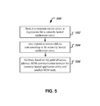
- FIG. 5 shows a flowchart example of a method 500 for facilitating Machine-to-Machine (M2M) communication.
- M2M Machine-to-Machine
- the method 500 includes, at 502 , hosting, at a CSE, a registration for a remotely hosted application entity, wherein the CSE comprises one or more service functions that are common to multiple M2M services.
- Some example service functions e.g., include, data management, device management, M2M subscription management, location services etc.
- the method 500 includes, at 504 , storing a point of access address corresponding to the remotely hosted application entity, wherein the remotely hosted application entity is on a different hardware platform than that of the CSE.
- the point of access address may be, e.g., a MAC address or an IP address of the remotely hosted AE.
- the remotely hosted AE may reside on a different hardware platform and may be reachable from the CSE over a communication network connection.
- the method 500 includes, at 506 , facilitating, based on the point of access address, M2M communication between the remotely hosted application entity and another M2M node.
- the point of access address may be an IP address or a MAC address.
- the method 500 may further include performing inter-CSE communication using Mcc reference point to facilitate allocation of resources and establishing connectivity between an AE and a requesting M2M node.
- a node at which the CSE of method 500 is implemented may receive information about an application resource structure corresponding to the remotely hosted application entity and may extract the point of access address from the application resource structure.
- the structure may be, e.g., as depicted in FIG. 4 .
- FIG. 6 show an example of an apparatus 600 for facilitating Machine-to-Machine (M2M) communication.
- the apparatus 600 includes a module 602 for hosting, at a common service entity, a registration for a remotely hosted application entity, a module 604 for storing a point of access address corresponding to the remotely hosted application entity and a module 606 for facilitating, based on the point of access address, M2M communication between the remotely hosted application entity and another M2M node.
- the point of access address may be an IP address or a MAC address.
- the disclosed and other embodiments and the functional operations and modules described in this document can be implemented in digital electronic circuitry, or in computer software, firmware, or hardware, including the structures disclosed in this document and their structural equivalents, or in combinations of one or more of them.
- the disclosed and other embodiments can be implemented as one or more computer program products, i.e., one or more modules of computer program instructions encoded on a computer readable medium for execution by, or to control the operation of, data processing apparatus.
- the computer readable medium can be a machine-readable storage device, a machine-readable storage substrate, a memory device, a composition of matter effecting a machine-readable propagated signal, or a combination of one or more them.
- data processing apparatus encompasses all apparatus, devices, and machines for processing data, including by way of example a programmable processor, a computer, or multiple processors or computers.
- the apparatus can include, in addition to hardware, code that creates an execution environment for the computer program in question, e.g., code that constitutes processor firmware, a protocol stack, a database management system, an operating system, or a combination of one or more of them.
- a propagated signal is an artificially generated signal, e.g., a machine-generated electrical, optical, or electromagnetic signal, that is generated to encode information for transmission to suitable receiver apparatus.
- a computer program (also known as a program, software, software application, script, or code) can be written in any form of programming language, including compiled or interpreted languages, and it can be deployed in any form, including as a stand alone program or as a module, component, subroutine, or other unit suitable for use in a computing environment.
- a computer program does not necessarily correspond to a file in a file system.
- a program can be stored in a portion of a file that holds other programs or data (e.g., one or more scripts stored in a markup language document), in a single file dedicated to the program in question, or in multiple coordinated files (e.g., files that store one or more modules, sub programs, or portions of code).
- a computer program can be deployed to be executed on one computer or on multiple computers that are located at one site or distributed across multiple sites and interconnected by a communication network.
- the processes and logic flows described in this document can be performed by one or more programmable processors executing one or more computer programs to perform functions by operating on input data and generating output.
- the processes and logic flows can also be performed by, and apparatus can also be implemented as, special purpose logic circuitry, e.g., an FPGA (field programmable gate array) or an ASIC (application specific integrated circuit).
- processors suitable for the execution of a computer program include, by way of example, both general and special purpose microprocessors, and any one or more processors of any kind of digital computer.
- a processor will receive instructions and data from a read only memory or a random access memory or both.
- the essential elements of a computer are a processor for performing instructions and one or more memory devices for storing instructions and data.
- a computer will also include, or be operatively coupled to receive data from or transfer data to, or both, one or more mass storage devices for storing data, e.g., magnetic, magneto optical disks, or optical disks.
- mass storage devices for storing data, e.g., magnetic, magneto optical disks, or optical disks.
- a computer need not have such devices.
- Computer readable media suitable for storing computer program instructions and data include all forms of non volatile memory, media and memory devices, including by way of example semiconductor memory devices, e.g., EPROM, EEPROM, and flash memory devices; magnetic disks, e.g., internal hard disks or removable disks; magneto optical disks; and CD ROM and DVD-ROM disks.
- semiconductor memory devices e.g., EPROM, EEPROM, and flash memory devices
- magnetic disks e.g., internal hard disks or removable disks
- magneto optical disks e.g., CD ROM and DVD-ROM disks.
- the processor and the memory can be supplemented by, or incorporated in, special purpose logic circuitry.
Landscapes
- Engineering & Computer Science (AREA)
- Computer Networks & Wireless Communication (AREA)
- Signal Processing (AREA)
- Health & Medical Sciences (AREA)
- Computing Systems (AREA)
- General Health & Medical Sciences (AREA)
- Medical Informatics (AREA)
- Mobile Radio Communication Systems (AREA)
- Computer Security & Cryptography (AREA)
- Telephonic Communication Services (AREA)
Abstract
In a machine to machine (M2M) communication system, a common service entity hosts a registration for a remotely hosted application entity, stores a point of access address corresponding to the remotely hosted application entity, and thereby facilitates M2M communication between the remotely hosted application entity and another M2M node. The communication may be performed over the Mca interface.
Description
This patent document claims the benefit of U.S. Provisional Patent Application No. 61/938,122, filed on Feb. 10, 2014. The entire content of the before-mentioned patent application is incorporated by reference as part of the disclosure of this document.
This document relates to machine-to-machine (M2M) communication.
M2M communication generally refers to communication between two different devices, which is not explicitly triggered by a user. Devices may perform M2M communication using wired or wireless connectivity. The communication is typically initiated by an application residing on one of the machine to gather or send information to a counterpart application on the other machine.
This document describes technologies, among other things, for facilitating communication between M2M devices. Using the disclosed techniques, in some embodiments, application level connectivity can be established between M2M nodes, irrespective of whether or not one of the nodes hosts a common service entity (CSE).
In one aspect, methods, systems and apparatus for facilitating M2M communications include hosting, at a common service entity, a registration for a remotely hosted application entity, storing a point of access address corresponding to the remotely hosted application entity, and facilitating, based on the point of access address, M2M communication between the remotely hosted application entity and another M2M node.
These and other aspects, and their implementations and variations are set forth in the drawings, the description and the claims.
Like reference symbols in the various drawings indicate like elements.
The following abbreviations are used in this document.
ADN: Application Dedicated Node.
ADN-AE: AE which resides in the Application Dedicated Node.
AE: Application Entity.
App: Application.
ASN: Application Service Node.
ASE-AE: Application Entity that is registered with the CSE in the Application Service Node.
ASN-CSE: CSE which resides in the Application Service Node.
BBF: Broadband Forum.
CSE: Common Service Entity.
CSF: Common Service Function.
EF: Enabler Function.
IEEE: Institute of Electrical and Electronics Engineers
IETF: Internet Engineering Task Force
IN: Infrastructure Node.
IN-AE: Application Entity that is registered with the CSE in the Infrastructure Node.
IN-CSE: CSE which resides in the Infrastructure Node.
JNI: Java Native Interface.
LTE: Long Term Evolution.
MAC: Medium Access Control.
M2M: Machine to machine.
MN: Middle Node.
MN-CSE: CSE which resides in the Middle Node.
NSE: Network Service Entity.
SDO: Standards development organization.
UNet: Underlying network (in which an M2M device resides).
In M2M communications, the two endpoints between which communication occurs often are in different networks. In a typical application scenario, one endpoint may be a sensor or a utility box that may go offline for extended time periods and another endpoint may be an application server such as a utility billing server or an M2M server that may be deployed in a managed network. Data packets traveling back and forth between these two end points may be routable via various routing options. For example, one endpoint may have connectivity over a licensed spectrum (e.g., Long Term Evolution) or an unlicensed spectrum (e.g., Wi-Fi). When one endpoint is offline for extended time periods, e.g., days or weeks, the way in which packets were routed to that end point during a last communication session may not necessarily the way in which the packets can be routed in a current communication session. Furthermore, various routing options may incur various costs (e.g., bandwidth charges or power dissipation during transmission).
In some implementations, radio stations 205 can communicate with each other based on a CDMA or GSM based air interface. In some implementations, radio stations 205 can communicate with each other based on an orthogonal frequency-division multiplexing (OFDM) air interface which can include Orthogonal Frequency-Division Multiple Access (OFDMA) air interface. In some implementations, radio stations 205 can communicate using one or more wireless technologies such as CDMA2000 1×, HRPD, WiMAX, GSM, LTE, and Universal Mobile Telecommunications System (UMTS).
In some implementations, a radio station 205 may additionally be configured with a local area network connectivity such as a 802.11 (a/b/g/n) interface. The availability of such an interface may make it possible to communicatively couple the radio station 205 to the Internet via the local area connection. For example, a user may access services over her user equipment (UE) by connecting to the service via a wireless local area network connection (e.g., home Wi-Fi access) through a fixed broadband network such as a cable modem network or a DSL network. The above described radio station 205 may be used to implement techniques disclosed in the present document, e.g., may represent an M2M node.
Service Layer specifications developed by organizations such as oneM2M, ETSI TC M2M, TIA TR-50 etc. (M2M SDOs) need to support efficient deployment of M2M Solutions by a wide range of market-focused (vertical) organizations. With the focus on the Service Layer, such organizations have been taking transport network-independent view of the end-to-end services. Yet, they need to make sure that their Service Layer specifications can be used effectively for interfacing with different types of transport networks. Such transport networks include but are not limited to the wireless and wireline networks being defined by 3GPP, 3GPP2, IEEE, IETF and BBF.
Some M2M systems provide for a CSE to facilitate communication among application level entities. However, not all entities/nodes are required to hosts CSE.
A CSE is an instantiation of one or more CSFs. A CSE provides a subset of CSFs that could be used and shared by M2M Applications. A CSE can utilize UNet capabilities and can interact with other CSEs to fulfil the service. A CSE comprises the set of “service functions” that are common to the M2M environments. Such service functions are exposed to other entities through Reference Points such as the Mca and Mcc reference points specified in oneM2M (see FIG. 3 ). The Mcc reference point defines communication flows between CSEs. The reference point Mcn is used for accessing Underlying Network Service Entities. Examples of service functions offered by CSE are: Data Management, Device Management, M2M Subscription Management, Location Services etc. Such “subfunctions” offered by a CSE may be logically apprehended as Common Services Functions (CSFs). Inside a Common Services Entity (CSE), some of the CSFs can be mandatory and others can be optional. Also, inside a CSF, some subfunctions can be mandatory or optional (e.g., inside a “Device Management” CSF, some of the subfunctions like “Application Software Installation”, “Firmware Updates”, “Logging”, “Monitoring”, etc. can be mandatory or optional).
A CSF is a set of service functions that are common to the M2M environment and specified by an interworking specification such as oneM2M.
As an example, in a oneM2M system, for entities/nodes that do not host CSEs (such as ADNs, Node-less-AEs), and when they register with a node that is CSE-capable, the registration results in the creation of an <application> resource at the CSE-capable Node. The reachability information for the AE provided in such <application> resource is presently limited to App-Inst-ID (Application Instance ID) only. In some embodiments, App-Inst-ID may not be sufficient for communication between a CSE and an AE that is located at a remote entity/node. A remote entity/node may be an entity/node that is not local, i.e., may have to be reached across a network communication path. Stated differently, no “pointOfAccess” information may be available for such registering-AE. With such lack of “pointOfAccess,” a remotely hosted AE cannot be reached over Mca reference point.
Using the disclosed techniques, in some embodiments, an address, such as IP address, MAC address etc. can be made available at the CSE that hosts registration for remotely hosted AE. Such address is termed as a “pointOfAccess” resource attribute in oneM2M. Such “pointOfAccess” can be included in the <application> resource for the remotely hosted CSE. An example pointOfAccess 402 listing is depicted in the <application> listing 400 of FIG. 4 .
Resource Type Application
The <application> resource represents information about an Application Entity known to a given Common Services Entity. FIG. 4 depicts an example 400 of application resource.
This resource may contain the child resources according to their multiplicity in Table 1 (0 indicates the optionality of the child resource). The term “multiplicity” refers to the number of independent instances of the resource that are available in an implementation.
| TABLE 1 | |||
| Child Resource | |||
| Name of | Child Resource | ||
| <Application> | Type | Multiplicity | Description |
| [variable] | <subscription> | 0 . . . n | |
| [variable] | <container> | 0 . . . n | |
| [variable] | <group> | 0 . . . n | |
| [variable] | <accessRight> | 0 . . . n | |
| software_[i] | <mgmtObj> | 1 . . . n | This resource represents the software |
| component (or components, if the multiplicity | |||
| is greater than 1) that compose the application. | |||
| This mgmtObj shall have at least the | |||
| following <parameters> child resources of its | |||
| “parameters” subresource: | |||
| name (multiplicity 1) | |||
| version (multiplicity 1) | |||
| state (multiplicity 1) | |||
| [variable] | <commCapabilities> | 1 . . . n | This resource describes the communication |
| capabilities (essentially the protocols) | |||
| supported and used by the corresponding | |||
| Application Entity over the Mca reference | |||
| point to this CSE. | |||
The <Application> resource may contain the attributes listed in Table 2.
| TABLE 2 | |||
| Attribute Name of | RW/RO/ | ||
| <Application> | Multiplicity | WO | |
| resourceType | |||
| 1 | RO | RO = Read only/RW = | |
| parentID | |||
| 1 | RO | ||
| expirationTime | 0 . . . 1 | | |
| accessRightID | |||
| 1 | | ||
| creationTime | |||
| 1 | | ||
| lastModifiedTime | |||
| 1 | RO | ||
| labels | 0 . . . 1 | | |
| name | |||
| 1 | RO | The (usually human readable) name of the | |
| application, as declared by the application | |||
| developer (e.g., “HeatingMonitoring”) | |||
| App- |
1 | RO | Application Identifier |
| App-Inst- |
1 | RO | When the application resource refers to an |
| actual application instance in the executing | |||
| environment. | |||
| pointOfAccess | 0 . . . n | RW | The list of addresses for communicating with |
| the registered Application Entity over Mca | |||
| reference point via the transport services | |||
| provided by Underlying Network (e.g., IP | |||
| address, FQDN). | |||
| ontologyRef | 0 . . . 1 | RW | A reference (URI) of the ontology used to |
| represent the information that is managed and | |||
| understood by the application; to be passed to | |||
| the application | |||
Another identifier, called “M2M Underlying Network Identifier” may be included in M2M implementations to further facilitate connectivity between nodes and AEs.
One or more Underlying Networks may be available at a Node offering different sets of capabilities (e.g., communication protocol, bandwidth, multimedia, etc.), availability schedules etc. Based on the “policy” information at the Node and the capabilities offered by the Underlying Networks, appropriate Underlying Network can be chosen. This identifier helps in identifying the chosen Underlying Network.
M2M Underlying Network Identifier (M2M-UNet-ID)
M2M Underlying Network Identifier (M2M-UNet-ID) is used by a node for identifying the UNet to be used for communicating with another Node.
One or more UNets may be available at a node offering different sets of capabilities, availability schedules etc. Based on the “policy” information at the node and the capabilities offered by the available UNet, appropriate UNet can be chosen. M2M-UNet-ID helps the Node in identifying the chosen UNet.
M2M-UNet-ID may be a static value and unique within a M2M Service Provider domain. Table 3 below provides additional examples of usage details of this resource identifier.
M2M Identifiers Lifecycle and Characteristics
| TABLE 3 | |||||||
| Identifier | Assigned by | Assigned to | Assigned during | Lifetime | Uniqueness | Used during | Remarks |
| CSE | M2M SP | CSE | During the | Life of the | Global | Information | |
| Identifier | first M2M | CSE | flows | ||||
| service | |||||||
| connection | |||||||
| unless pre- | |||||||
| provisioned | |||||||
| M2M Node | M2M SP | M2M Node | Pre- | Life of the | Global | Out of | |
| Identifier | hosting CSE | provisioned | M2M Node | scope | |||
| M2M | M2M SP | Underlying | Pre- | Life of the | Local to | UL | |
| Underlying | Networks | provisioned | Underlying | M2M SP | Network | ||
| Network | Network | domain | selection | ||||
| Identifier | |||||||
| M2M | M2M SP | AEs, and one | At service | Life of the | Global | Charging and | Multiple |
| Subscription | or more CSEs | signup | Subscription | Information | CSEs can be | ||
| Identifier | belonging to | with the MM | Recorded | allocated | |||
| the same M2M | SP | Other | the same M2M | ||||
| subscriber | operations | Subscription | |||||
| are FFS | Identifier | ||||||
As one example of implementation, the oneM2M Functional Architecture 300 shown in FIG. 3 supports Application Entities (AEs) on Nodes that provide CSE capability (e.g., ASN, MN, IN), as well as on Nodes that do not provide such CSE capability (e.g., ADNs, Node-less AEs). AEs local on a CSE-capable Node register with the local CSE. AEs on non-CSE-capable Nodes will register with a CSE-capable Node in order to receive services. The CSE-capable Node, in turn, registers with other CSE-capable Nodes, including CSE-capable Infrastructure Node (M2M Server) for communication (services) over Mcc reference point. Such communication can be enabled by the use of “pointOfAccess” attribute in the <remoteCSE> resource structure that is created at the two peer CSE-capable registering Nodes.
For entities/nodes that do not host CSEs (e.g., ADNs, node-less-AEs), registration with a Node that is CSE-capable, results in the creation of another type of resource at the CSE-capable Node. Such resource is called <application> resource. The reachability information for the AE provided in such <application> resource is limited to App-Inst-ID (Application Instance ID) only. In some scenarios, the App-Inst-ID is not sufficient for communication between a CSE and an AE that is located at a remote entity/Node. Stated differently, no “pointOfAccess” information is available for such registering-AE. With such lack of “pointOfAccess,” i.e., information about how to access a remotely hosted AE, the remotely hosted AE cannot be reached over Mca reference point.
Another aspect for consideration is that one or more Underlying Networks may be available at a Node (ASN, ADN, MN, IN) offering different sets of capabilities, availability schedules etc. based on the “policy” information at the Node and capabilities offered by the Underlying Networks, appropriate UNet can be chosen. The resource identifier of the underlying network, e.g., M2M Underlying Network Identifier: M2M-UNet-ID, helps in identifying the chosen UNet to the node.
Various embodiments can provide an address, such as IP address, MAC address etc. that is available at the CSE that hosts registration for remotely hosted AE. Any such address can be considered to populate the “pointOfAccess” resource field. Such “pointOfAccess” can be included in the <application> resource for the remotely hosted CSE.
In some embodiments, an identifier, such as M2M-UNet-ID, can be made available at every node that communicates with another node over an UNet. Such identifier will be unique within the domain of the M2M Service Provider.
Example Communication Systems
In this example illustration, Application Entities (AEs) on ADN (ADN-AEs) may register with IN-CSE. Similarly Node-less AEs can register with IN-CSE. ADN-AEs may register with MN-CSE as well. Such registrations are registrations between AEs and CSEs at remote entities/Nodes.
Address, such as the IP address, MAC address etc. is needed at the CSE for communicating with the AEs on the remote entity. Such address is termed as “pointOfAccess” in this document. Such communication may be over Mca reference point via the transport services provided by the Underlying Network that provides connectivity between the remote entities.
In some embodiments, the information about “pointOfAccess” will be usable at the AEs as well.
The method 500 includes, at 502, hosting, at a CSE, a registration for a remotely hosted application entity, wherein the CSE comprises one or more service functions that are common to multiple M2M services. Some example service functions, e.g., include, data management, device management, M2M subscription management, location services etc.
The method 500 includes, at 504, storing a point of access address corresponding to the remotely hosted application entity, wherein the remotely hosted application entity is on a different hardware platform than that of the CSE. The point of access address may be, e.g., a MAC address or an IP address of the remotely hosted AE. The remotely hosted AE may reside on a different hardware platform and may be reachable from the CSE over a communication network connection.
The method 500 includes, at 506, facilitating, based on the point of access address, M2M communication between the remotely hosted application entity and another M2M node. In some embodiments the point of access address may be an IP address or a MAC address. At 506, the method 500 may further include performing inter-CSE communication using Mcc reference point to facilitate allocation of resources and establishing connectivity between an AE and a requesting M2M node.
A node at which the CSE of method 500 is implemented may receive information about an application resource structure corresponding to the remotely hosted application entity and may extract the point of access address from the application resource structure. The structure may be, e.g., as depicted in FIG. 4 .
The disclosed and other embodiments and the functional operations and modules described in this document can be implemented in digital electronic circuitry, or in computer software, firmware, or hardware, including the structures disclosed in this document and their structural equivalents, or in combinations of one or more of them. The disclosed and other embodiments can be implemented as one or more computer program products, i.e., one or more modules of computer program instructions encoded on a computer readable medium for execution by, or to control the operation of, data processing apparatus. The computer readable medium can be a machine-readable storage device, a machine-readable storage substrate, a memory device, a composition of matter effecting a machine-readable propagated signal, or a combination of one or more them. The term “data processing apparatus” encompasses all apparatus, devices, and machines for processing data, including by way of example a programmable processor, a computer, or multiple processors or computers. The apparatus can include, in addition to hardware, code that creates an execution environment for the computer program in question, e.g., code that constitutes processor firmware, a protocol stack, a database management system, an operating system, or a combination of one or more of them. A propagated signal is an artificially generated signal, e.g., a machine-generated electrical, optical, or electromagnetic signal, that is generated to encode information for transmission to suitable receiver apparatus.
A computer program (also known as a program, software, software application, script, or code) can be written in any form of programming language, including compiled or interpreted languages, and it can be deployed in any form, including as a stand alone program or as a module, component, subroutine, or other unit suitable for use in a computing environment. A computer program does not necessarily correspond to a file in a file system. A program can be stored in a portion of a file that holds other programs or data (e.g., one or more scripts stored in a markup language document), in a single file dedicated to the program in question, or in multiple coordinated files (e.g., files that store one or more modules, sub programs, or portions of code). A computer program can be deployed to be executed on one computer or on multiple computers that are located at one site or distributed across multiple sites and interconnected by a communication network.
The processes and logic flows described in this document can be performed by one or more programmable processors executing one or more computer programs to perform functions by operating on input data and generating output. The processes and logic flows can also be performed by, and apparatus can also be implemented as, special purpose logic circuitry, e.g., an FPGA (field programmable gate array) or an ASIC (application specific integrated circuit).
Processors suitable for the execution of a computer program include, by way of example, both general and special purpose microprocessors, and any one or more processors of any kind of digital computer. Generally, a processor will receive instructions and data from a read only memory or a random access memory or both. The essential elements of a computer are a processor for performing instructions and one or more memory devices for storing instructions and data. Generally, a computer will also include, or be operatively coupled to receive data from or transfer data to, or both, one or more mass storage devices for storing data, e.g., magnetic, magneto optical disks, or optical disks. However, a computer need not have such devices. Computer readable media suitable for storing computer program instructions and data include all forms of non volatile memory, media and memory devices, including by way of example semiconductor memory devices, e.g., EPROM, EEPROM, and flash memory devices; magnetic disks, e.g., internal hard disks or removable disks; magneto optical disks; and CD ROM and DVD-ROM disks. The processor and the memory can be supplemented by, or incorporated in, special purpose logic circuitry.
While this document contains many specifics, these should not be construed as limitations on the scope of an invention that is claimed or of what may be claimed, but rather as descriptions of features specific to particular embodiments. Certain features that are described in this document in the context of separate embodiments can also be implemented in combination in a single embodiment. Conversely, various features that are described in the context of a single embodiment can also be implemented in multiple embodiments separately or in any suitable sub-combination. Moreover, although features may be described above as acting in certain combinations and even initially claimed as such, one or more features from a claimed combination can in some cases be excised from the combination, and the claimed combination may be directed to a sub-combination or a variation of a sub-combination. Similarly, while operations are depicted in the drawings in a particular order, this should not be understood as requiring that such operations be performed in the particular order shown or in sequential order, or that all illustrated operations be performed, to achieve desirable results.
Only a few examples and implementations are disclosed. Variations, modifications, and enhancements to the described examples and implementations and other implementations can be made based on what is disclosed.
Claims (18)
1. A method for facilitating Machine-to-Machine (M2M) communication, the method comprising:
hosting, at a common service entity (CSE), a registration for a remotely hosted application entity, wherein the CSE comprises one or more service functions that are common to multiple M2M services;
creating, by the common service entity, a resource for the remotely hosted application entity upon the registration of the remotely hosted application entity;
storing, by the common service entity, a point of access address of the remotely hosted application entity in the resource for the remotely hosted application entity such that the remotely hosted application entity is reachable over a reference point between the CSE and the remotely hosted application entity, wherein the remotely hosted application entity is on a different hardware platform than that of the CSE; and
facilitating, based on the point of access address, M2M communication between the remotely hosted application entity and an M2M node.
2. The method of claim 1 , wherein the point of access address comprises one of an internet protocol (IP) address and a medium access control (MAC) address.
3. The method of claim 1 , wherein the remotely hosted application entity resides in an underlying network that is different from that of the CSE.
4. The method of claim 1 , wherein the facilitating the M2M communication comprises communicating with another CSE using a pre-defined protocol for inter-CSE communication over an underlying network that is identified.
5. An apparatus for facilitating Machine-to-Machine (M2M) communication comprising:
a module that hosts, at a common service entity, a registration for a remotely hosted application entity;
a module that creates, at the common service entity, a resource for the remotely hosted application entity upon the registration of the remotely hosted application entity;
a module that stores a point of access address of the remotely hosted application entity in the resource for the remotely hosted application entity such that the remotely hosted application entity is reachable over a reference point between the common service entity and the remotely hosted application entity, wherein the remotely hosted application entity is on a different hardware platform than that of the common service entity; and
a module that facilitates, based on the point of access address, M2M communication between the remotely hosted application entity and another M2M node.
6. The apparatus of claim 5 , wherein the point of access address comprises an internet protocol (IP) address.
7. The apparatus of claim 5 , wherein the point of access address comprises a medium access control (MAC) address.
8. The apparatus of claim 5 , wherein the reference point between the common service entity and the remotely hosted application entity includes an Mca interface, and wherein the module that facilitates the M2M communication comprises a module that facilitates the M2M communication over the Mca interface.
9. A computer program product that includes a non-transitory computer-readable medium having code stored thereon, the code, when executed by a processor, causing the processor to implement, a method for facilitating Machine-to-Machine (M2M) communication, the method comprising:
hosting, at a common service entity (CSE), a registration for a remotely hosted application entity, wherein the CSE comprises one or more service functions that are common to multiple M2M services;
creating, by the common service entity, a resource for the remotely hosted application entity upon the registration of the remotely hosted application entity;
storing, by the common service entity, a point of access address of the remotely hosted application entity in the resource for the remotely hosted application entity such that the remotely hosted application entity is reachable over a reference point between the CSE and the remotely hosted application entity, wherein the remotely hosted application entity is on a different hardware platform than that of the CSE; and
facilitating, based on the point of access address, M2M communication between the remotely hosted application entity and an M2M node.
10. The computer program product of claim 9 , wherein the point of access address comprises one of an internet protocol (IP) address and a medium access control (MAC) address.
11. The computer program product of claim 9 , wherein the remotely hosted application entity resides in an underlying network that is different from that of the CSE.
12. The computer program product of claim 9 , wherein the facilitating the M2M communication comprises communicating with another CSE using a pre-defined protocol for inter-CSE communication over an underlying network that is identified.
13. A machine to machine communication system comprising a common service entity; a remote application entity;
a module that hosts, at the common service entity, a registration for the remote application entity;
a module that creates, at the common service entity, a resource for the remotely hosted application entity upon the registration of the remotely hosted application entity;
a module that stores a point of access address of the remote application entity in the resource for the remotely hosted application entity such that the remotely hosted application entity is reachable over a reference point between the common service entity and the remotely hosted application entity, wherein the remotely hosted application entity is on a different hardware platform than that of the common service entity; and
a module that facilitates, based on the point of access address, M2M communication between the remote application entity and another M2M node.
14. The machine to machine communication system of claim 13 , wherein the point of access address comprises an internet protocol (IP) address.
15. The machine to machine communication system of claim 13 , wherein the point of access address comprises a medium access control (MAC) address.
16. The machine to machine communication system of claim 13 , wherein the reference point between the common service entity and the remotely hosted application entity is an Mca interface, and wherein the module that facilitates the M2M communication comprises a module that facilitates the M2M communication over the Mca interface.
17. A method for facilitating Machine-to-Machine (M2M) communication comprising:
receiving, at a common service entity (CSE), a resource for a remotely hosted application entity;
extracting a point of access address from the resource for the remotely hosted application entity such that the remotely hosted application entity is reachable over a reference point between the common service entity and the remotely hosted application entity, wherein the remotely hosted application entity is on a different hardware platform than that of the CSE; and
facilitating, based on the point of access address, M2M communication between the remotely hosted application entity and an M2M node.
18. An apparatus for facilitating Machine-to-Machine (M2M) communication comprising:
a receiver configured to receive, at a common service entity (CSE), a resource for a remotely hosted application entity; and
a processor configured to read instruction from a non-transitory computer-readable medium and perform:
extracting a point of access address from the resource for the remotely hosted application entity so that the remotely hosted application entity is reachable over a reference point between the common service entity and the remotely hosted application entity, wherein the remotely hosted application entity is on a different hardware platform than that of the CSE; and
facilitating, based on the point of access address, M2M communication between the remotely hosted application entity and another M2M node.
Priority Applications (1)
| Application Number | Priority Date | Filing Date | Title |
|---|---|---|---|
| US15/118,074 US10136244B2 (en) | 2014-02-10 | 2015-02-10 | Extending connectivity in a machine to machine communication system |
Applications Claiming Priority (3)
| Application Number | Priority Date | Filing Date | Title |
|---|---|---|---|
| US201461938122P | 2014-02-10 | 2014-02-10 | |
| US15/118,074 US10136244B2 (en) | 2014-02-10 | 2015-02-10 | Extending connectivity in a machine to machine communication system |
| PCT/US2015/015280 WO2015120480A1 (en) | 2014-02-10 | 2015-02-10 | Extending connectivity in a machine to machine communication system |
Publications (2)
| Publication Number | Publication Date |
|---|---|
| US20160360340A1 US20160360340A1 (en) | 2016-12-08 |
| US10136244B2 true US10136244B2 (en) | 2018-11-20 |
Family
ID=53778555
Family Applications (1)
| Application Number | Title | Priority Date | Filing Date |
|---|---|---|---|
| US15/118,074 Active US10136244B2 (en) | 2014-02-10 | 2015-02-10 | Extending connectivity in a machine to machine communication system |
Country Status (6)
| Country | Link |
|---|---|
| US (1) | US10136244B2 (en) |
| EP (1) | EP3105911B1 (en) |
| JP (1) | JP6523313B2 (en) |
| KR (1) | KR101922100B1 (en) |
| CN (1) | CN106165375A (en) |
| WO (1) | WO2015120480A1 (en) |
Cited By (2)
| Publication number | Priority date | Publication date | Assignee | Title |
|---|---|---|---|---|
| US20200257968A1 (en) * | 2019-02-08 | 2020-08-13 | Adobe Inc. | Self-learning scheduler for application orchestration on shared compute cluster |
| US11470168B2 (en) * | 2017-10-12 | 2022-10-11 | Convida Wireless, Llc | Interworking service for the restful internet of things |
Families Citing this family (9)
| Publication number | Priority date | Publication date | Assignee | Title |
|---|---|---|---|---|
| KR101908717B1 (en) | 2014-02-10 | 2018-10-17 | 지티이 코포레이션 | Enabling different device triggering aspects in a machine to machine communication system |
| KR101924839B1 (en) | 2014-02-10 | 2018-12-05 | 지티이 코포레이션 | Techniques for mapping machine to machine communication to different underlying networks |
| JP6523313B2 (en) * | 2014-02-10 | 2019-05-29 | 中興通訊股▲ふん▼有限公司Zte Corporation | Connectivity Enhancement in Machine-to-Machine Communication Systems |
| US20160072839A1 (en) * | 2014-09-05 | 2016-03-10 | Salesforce.Com, Inc. | Facilitating dynamic management of participating devices within a network in an on-demand services environment |
| CN108353263B (en) * | 2015-10-30 | 2021-02-09 | Lg 电子株式会社 | Method of processing service request in wireless communication system and apparatus therefor |
| CN107317785B (en) | 2016-04-26 | 2021-04-23 | 京东方科技集团股份有限公司 | Application entity creation resource and registration method, communication node device and terminal device |
| CN108235281B (en) | 2016-12-12 | 2023-09-22 | 京东方科技集团股份有限公司 | Application entity creation resources and registration methods, communication node equipment and terminal equipment |
| US10499189B2 (en) * | 2017-12-14 | 2019-12-03 | Cisco Technology, Inc. | Communication of data relating to endpoint devices |
| KR20220071882A (en) * | 2020-11-24 | 2022-05-31 | 현대자동차주식회사 | Method and apparatus for replacing parts of device in machine to machine system |
Citations (26)
| Publication number | Priority date | Publication date | Assignee | Title |
|---|---|---|---|---|
| US20110213871A1 (en) | 2010-03-01 | 2011-09-01 | Interdigital Patent Holdings, Inc. | Machine-to-machine gateway architecture and functionality |
| US20120296968A1 (en) | 2011-02-03 | 2012-11-22 | Telcordia Technologies, Inc. | System and Method for Group Communications in 3GPP Machine-to-Machine Networks |
| US20130003609A1 (en) | 2010-01-05 | 2013-01-03 | Jean-Marc Ballot | Handling of m2m services in a communication system |
| US20130013793A1 (en) | 2010-02-19 | 2013-01-10 | Telefonaktiebolaget Lm Ericsson (Publ) | Apparatuses and methods for handling machineto-machine communications |
| US20130016657A1 (en) | 2011-07-15 | 2013-01-17 | Ahmad Muhanna | Dynamic enablement of m2m services over 3gpp access networks |
| US20130060664A1 (en) * | 2008-12-18 | 2013-03-07 | Bulletin.Net Inc. | Systems And Methods For Using Symbol Command Language Within A Communications Network |
| US20130094444A1 (en) | 2011-10-13 | 2013-04-18 | Applied Communications Sciences | Automatic provisioning of an m2m device having a wifi interface |
| US20130103842A1 (en) | 2011-10-24 | 2013-04-25 | Interdigital Patent Holdings, Inc. | Methods, systems and apparatuses for application service layer (asl) inter-networking |
| WO2013073747A1 (en) | 2011-11-14 | 2013-05-23 | Lg Electronics Inc. | M2m communication via another scl |
| WO2013074849A1 (en) | 2011-11-15 | 2013-05-23 | Zte (Usa) Inc. | Triggering machine-to-machine device communication in wireless networks |
| US20130157673A1 (en) | 2011-09-16 | 2013-06-20 | Alcatel-Lucent Usa Inc. | Network operator-neutral provisioning of mobile devices |
| US20130188515A1 (en) | 2010-03-09 | 2013-07-25 | Interdigital Patent Holdings, Inc. | Method and apparatus for supporting machine-to-machine communications |
| US20130203412A1 (en) | 2012-02-03 | 2013-08-08 | Interdigital Patent Holdings, Inc. | Identifiers and triggers for capillary devices |
| US20130250968A1 (en) | 2010-11-24 | 2013-09-26 | Huawei Technologies Co.,Ltd. | Method and network entity for obtaining ip address of user |
| WO2013171722A2 (en) | 2012-05-18 | 2013-11-21 | Telefonaktiebolaget L M Ericsson (Publ) | Automatic transfer of machine-to-machine device identifier to network-external service providers |
| US20130332627A1 (en) | 2011-02-25 | 2013-12-12 | Telefonaktiebolaget L M Ericsson (Publ) | Enabling ip-communication with a machine to machine unit |
| US20130343538A1 (en) | 2012-06-20 | 2013-12-26 | Semyon Mizikovsky | Manipulation and restoration of authentication challenge parameters in network authentication procedures |
| US20130346504A1 (en) | 2011-02-25 | 2013-12-26 | Huawei Technologies Co., Ltd. | Group communication method and apparatus for group communication |
| WO2013190402A1 (en) | 2012-06-22 | 2013-12-27 | Telefonaktiebolaget L M Ericsson (Publ) | Selection of m2m devices by external triggering |
| WO2015120477A1 (en) | 2014-02-10 | 2015-08-13 | Zte Corporation | Enabling different device triggering aspects in a machine to machine communication system |
| WO2015120484A1 (en) | 2014-02-10 | 2015-08-13 | Zte Corporation | Techniques for mapping machine to machine communication to different underlying networks |
| US20150264634A1 (en) | 2012-09-28 | 2015-09-17 | Fu Ding | Provisioning external identifiers |
| US20150350904A1 (en) * | 2012-12-05 | 2015-12-03 | Lg Electronics Inc. | Method and apparatus for authenticating access authorization in wireless communication system |
| US20150358874A1 (en) * | 2013-01-11 | 2015-12-10 | Lg Electronics Inc. | Method for changing gateway in machine-to-machine (m2m) system and device therefor |
| US20160360340A1 (en) * | 2014-02-10 | 2016-12-08 | Zte Corporation | Extending connectivity in a machine to machine communication system |
| US20170026774A1 (en) | 2013-11-29 | 2017-01-26 | Ntt Docomo, Inc. | Communication system, service control device, mtc user device, gateway device, and communication method |
Family Cites Families (3)
| Publication number | Priority date | Publication date | Assignee | Title |
|---|---|---|---|---|
| CN102111288A (en) * | 2009-12-24 | 2011-06-29 | 中兴通讯股份有限公司 | Machine to machine (M2M) network management architecture |
| KR101963466B1 (en) * | 2011-02-11 | 2019-03-28 | 아이오티 홀딩스, 인크. | Systems, methods and apparatus for managing machine-to-machine (m2m) entities |
| EP3425942A1 (en) * | 2012-01-13 | 2019-01-09 | Iot Holdings, Inc. | Method and apparatus for supporting machine-to-machine communications |
-
2015
- 2015-02-10 JP JP2016551158A patent/JP6523313B2/en active Active
- 2015-02-10 WO PCT/US2015/015280 patent/WO2015120480A1/en not_active Ceased
- 2015-02-10 KR KR1020167024576A patent/KR101922100B1/en active Active
- 2015-02-10 EP EP15747056.8A patent/EP3105911B1/en active Active
- 2015-02-10 US US15/118,074 patent/US10136244B2/en active Active
- 2015-02-10 CN CN201580019110.5A patent/CN106165375A/en not_active Withdrawn
Patent Citations (29)
| Publication number | Priority date | Publication date | Assignee | Title |
|---|---|---|---|---|
| US20130060664A1 (en) * | 2008-12-18 | 2013-03-07 | Bulletin.Net Inc. | Systems And Methods For Using Symbol Command Language Within A Communications Network |
| US20130003609A1 (en) | 2010-01-05 | 2013-01-03 | Jean-Marc Ballot | Handling of m2m services in a communication system |
| US20130013793A1 (en) | 2010-02-19 | 2013-01-10 | Telefonaktiebolaget Lm Ericsson (Publ) | Apparatuses and methods for handling machineto-machine communications |
| US20110213871A1 (en) | 2010-03-01 | 2011-09-01 | Interdigital Patent Holdings, Inc. | Machine-to-machine gateway architecture and functionality |
| US20130188515A1 (en) | 2010-03-09 | 2013-07-25 | Interdigital Patent Holdings, Inc. | Method and apparatus for supporting machine-to-machine communications |
| US20130250968A1 (en) | 2010-11-24 | 2013-09-26 | Huawei Technologies Co.,Ltd. | Method and network entity for obtaining ip address of user |
| US20120296968A1 (en) | 2011-02-03 | 2012-11-22 | Telcordia Technologies, Inc. | System and Method for Group Communications in 3GPP Machine-to-Machine Networks |
| US20130332627A1 (en) | 2011-02-25 | 2013-12-12 | Telefonaktiebolaget L M Ericsson (Publ) | Enabling ip-communication with a machine to machine unit |
| US20130346504A1 (en) | 2011-02-25 | 2013-12-26 | Huawei Technologies Co., Ltd. | Group communication method and apparatus for group communication |
| US20130016657A1 (en) | 2011-07-15 | 2013-01-17 | Ahmad Muhanna | Dynamic enablement of m2m services over 3gpp access networks |
| US20130157673A1 (en) | 2011-09-16 | 2013-06-20 | Alcatel-Lucent Usa Inc. | Network operator-neutral provisioning of mobile devices |
| US20130094444A1 (en) | 2011-10-13 | 2013-04-18 | Applied Communications Sciences | Automatic provisioning of an m2m device having a wifi interface |
| US20130103842A1 (en) | 2011-10-24 | 2013-04-25 | Interdigital Patent Holdings, Inc. | Methods, systems and apparatuses for application service layer (asl) inter-networking |
| WO2013073747A1 (en) | 2011-11-14 | 2013-05-23 | Lg Electronics Inc. | M2m communication via another scl |
| WO2013074849A1 (en) | 2011-11-15 | 2013-05-23 | Zte (Usa) Inc. | Triggering machine-to-machine device communication in wireless networks |
| US20130203412A1 (en) | 2012-02-03 | 2013-08-08 | Interdigital Patent Holdings, Inc. | Identifiers and triggers for capillary devices |
| WO2013171722A2 (en) | 2012-05-18 | 2013-11-21 | Telefonaktiebolaget L M Ericsson (Publ) | Automatic transfer of machine-to-machine device identifier to network-external service providers |
| US20140086144A1 (en) | 2012-05-18 | 2014-03-27 | Telefonaktiebolaget L M Ericsson (Publ) | Automatic Transfer of Machine-to-Machine Device Identifier to Network-External Service Providers |
| US20130343538A1 (en) | 2012-06-20 | 2013-12-26 | Semyon Mizikovsky | Manipulation and restoration of authentication challenge parameters in network authentication procedures |
| WO2013190402A1 (en) | 2012-06-22 | 2013-12-27 | Telefonaktiebolaget L M Ericsson (Publ) | Selection of m2m devices by external triggering |
| US20150264634A1 (en) | 2012-09-28 | 2015-09-17 | Fu Ding | Provisioning external identifiers |
| US20150350904A1 (en) * | 2012-12-05 | 2015-12-03 | Lg Electronics Inc. | Method and apparatus for authenticating access authorization in wireless communication system |
| US20150358874A1 (en) * | 2013-01-11 | 2015-12-10 | Lg Electronics Inc. | Method for changing gateway in machine-to-machine (m2m) system and device therefor |
| US20170026774A1 (en) | 2013-11-29 | 2017-01-26 | Ntt Docomo, Inc. | Communication system, service control device, mtc user device, gateway device, and communication method |
| WO2015120477A1 (en) | 2014-02-10 | 2015-08-13 | Zte Corporation | Enabling different device triggering aspects in a machine to machine communication system |
| WO2015120484A1 (en) | 2014-02-10 | 2015-08-13 | Zte Corporation | Techniques for mapping machine to machine communication to different underlying networks |
| US20160359797A1 (en) | 2014-02-10 | 2016-12-08 | Zte Corporation | Techniques for mapping machine to machine communication to different underlying networks |
| US20160360340A1 (en) * | 2014-02-10 | 2016-12-08 | Zte Corporation | Extending connectivity in a machine to machine communication system |
| US20160366716A1 (en) | 2014-02-10 | 2016-12-15 | Zte Corporation | Enabling different device triggering aspects in a machine to machine communication system |
Non-Patent Citations (35)
| Title |
|---|
| "Machine-to-Machine communications (M2M); Functional architecture," ETSI TS 102 690 v2.1.1, Technical Specification, 332 pages, Oct. 2013. |
| 3GPP TSG SA WG2 Meeting #78, "Device triggering and E.164 MSISDN replacement," TD S2-101169, San Francisco, California, USA, pp. 1-4, Feb. 2010. |
| Bhalla, R., "Discussions on Triggering Aspects in oneM2M," oneM2M Input Contribution, oneM2M Partners, Doc# ARC-2014-0125-Discussion on Triggering Aspects in oneM2M, pp. 1-13, Feb. 2014. |
| Bhalla, R., "M2M-Node-ID attribute for non-CSE Capable AEs," oneM2M Input Contribution, oneM2M Partners, Doc# ARC-2014-0126-M2M-Node-ID for non-CSE capable Entities, pp. 1-5, Feb. 2014. |
| Bhalla, R., "pointOfAccess attribute for non-CSE Capable AEs," oneM2M Input Contribution, oneM2M Partners, Doc# ARC-2014-0123-pointOfAccess for AEs on non-CSE capable Entities, pp. 1-5, Feb. 2014. |
| Bhalla, R., "Some Enhancements for Supporting Device Triggering," oneM2M Input Contribution, oneM2M Partners, Doc# ARC-2014-0127-some enhancements for supporting device triggering, pp. 1-4, Feb. 2014. |
| Bhalla, R., "Underlying Network Identifier," oneM2M Input Contribution, oneM2M Partners, Doc# Arc-2014-0124-Underlying Network Identifier, pp. 1-3, Feb. 2014. |
| Bhalla, R., "Discussions on Triggering Aspects in oneM2M," oneM2M Input Contribution, oneM2M Partners, Doc# ARC-2014-0125—Discussion on Triggering Aspects in oneM2M, pp. 1-13, Feb. 2014. |
| Bhalla, R., "M2M-Node-ID attribute for non-CSE Capable AEs," oneM2M Input Contribution, oneM2M Partners, Doc# ARC-2014-0126-M2M—Node-ID for non-CSE capable Entities, pp. 1-5, Feb. 2014. |
| Bhalla, R., "pointOfAccess attribute for non-CSE Capable AEs," oneM2M Input Contribution, oneM2M Partners, Doc# ARC-2014-0123—pointOfAccess for AEs on non-CSE capable Entities, pp. 1-5, Feb. 2014. |
| Bhalla, R., "Some Enhancements for Supporting Device Triggering," oneM2M Input Contribution, oneM2M Partners, Doc# ARC-2014-0127—some enhancements for supporting device triggering, pp. 1-4, Feb. 2014. |
| Bhalla, R., "Underlying Network Identifier," oneM2M Input Contribution, oneM2M Partners, Doc# Arc-2014-0124—Underlying Network Identifier, pp. 1-3, Feb. 2014. |
| Bhalla, R., et al., "Application Port ID," oneM2M Input Contribution, oneM2M Partners, Doc# ARC-2014-1179-Application_Port_ID.Doc, pp. 1-8, Feb. 2014. |
| Bhalla, R., et al., "Application Port ID," oneM2M Input Contribution, oneM2M Partners, Doc# ARC-2014-1179—Application_Port_ID.Doc, pp. 1-8, Feb. 2014. |
| European Extended Search Report dated Feb. 2, 2017 for European Patent Application No. 15746113.8, filed on Feb. 10, 2015 (8 pages). |
| European Extended Search Report dated Feb. 2, 2017 for European Patent Application No. 15747056.8, filed on Feb. 10, 2015 (10 pages). |
| European Extended Search Report dated Feb. 6, 2017 for European Patent Application No. 15747005.5, filed on Feb. 10, 2015 (12 pages). |
| Foti, G., et al., "Functional architecture in oneM2M-TS-0001 oneM2M Functional Architecture-V-0.01," oneM2M Input Contribution, oneM2M Partners, Doc# oneM2M-Arc-2013-0347, pp. 1-3, Jul. 2013. |
| Foti, G., et al., "Functional architecture in oneM2M-TS-0001 oneM2M Functional Architecture—V-0.01," oneM2M Input Contribution, oneM2M Partners, Doc# oneM2M-Arc-2013-0347, pp. 1-3, Jul. 2013. |
| International Search Report and Written Opinion dated Apr. 28, 2015 for International Application No. PCT/US2015/015274, filed on Feb. 10, 2015 (11 pages). |
| International Search Report and Written Opinion dated Apr. 28, 2015 for International Application No. PCT/US2015/015280, filed Feb. 10, 2015 (7 pages). |
| International Search Report and Written Opinion dated Apr. 28, 2015 for International Application No. PCT/US2015/015287, filed on Feb. 10, 2015 (10 pages). |
| Jacobs, P., et al., "WI 0002-onem2m Architecture; Technical Specification-M2M Architecture," oneM2M Partners, pp. 1-4, Dec. 2013, Retrieved from the Internet <URL:http://ftp.onem2m.org/meetings/ARC/2013-meetings/20131209_ARC8.0_Miyazaki/oneM2M-ARC-2013-0509R04-Revision_of figure_6-1.DOC> [retrieved on Jan. 26, 2017]. |
| Jacobs, P., et al., "WI 0002—onem2m Architecture; Technical Specification—M2M Architecture," oneM2M Partners, pp. 1-4, Dec. 2013, Retrieved from the Internet <URL:http://ftp.onem2m.org/meetings/ARC/2013-meetings/20131209_ARC8.0_Miyazaki/oneM2M-ARC-2013-0509R04-Revision_of figure_6-1.DOC> [retrieved on Jan. 26, 2017]. |
| Katusic, D., et al., "Universal Identification Scheme in Machine-to-Machine Systems," IEEE Proceedings of the 12th International Conference on Telecommunications (ConTEL 2013), Zagreb, Croatia, pp. 71-78, Jun. 2013. |
| Kim, S., et al., "Overall Procedure Discussion related to Security," oneM2M Partners, pp. 1-9, Jan. 2014, Retrieved from the Internet <URL:http://ftp.onem2m.org/meetings/SEC/2014 meetings/20140115_SEC-ah/SEC-2014-0008-Overall_Procedure_Discussion_related_to_Security.PPT> [retrieved on Jan. 26, 2017]. |
| Office Action dated Oct. 10, 2017 for Japanese Patent Application No. 2016-551238, filed on Feb. 10, 2015 (9 pages). |
| Office Action dated Oct. 17, 2017 for Japanese Patent Application No. 2016-551158, filed on Feb. 10, 2015 (5 pages). |
| Office Action dated Sep. 26, 2017 for Japanese Patent Application No. 2016-551156, filed on Feb. 10, 2015 (4 pages). |
| OneM2M Technical Specification, "oneM2M Functional Architecture Baseline Draft," oneM2M Partners, Doc# oneM2M TS-0001-V-2014-08, pp. 1-297, Aug. 2014, <URL:http://www.onem2m.org/images/files/deliverables/TS-0001-oneM2M-Functional-Architecture-V-2014-08.pdf>. |
| OneM2M Technical Specification, "oneM2M Functional Architecture," oneM2M Partners, Doc# oneM2M-TS-0001-V-0.3.2, pp. 1-171, Jan. 2014, <URL:http://ftp.onem2m.org/Meetings/ARC/2014%20meetings/20140109_ARC8.1/ARC-2014-0618R02-Functional_Architecture_Spec_TS-0001_v0_3_2_Draft-Baseline.ZIP>. |
| OneM2M Technical Specification, "oneM2M Functional Architecture," oneM2M Partners, Doc# oneM2M-TS-0001-V-0A.0, pp. 1-169, Feb. 2014, <URL:http://member.onem2m.org/Application/documentapp/downloadimmediate/default.aspx?docID=4723>. |
| OneM2M Technical Specification, "oneM2M Functional Architecture," oneM2M Partners, Doc# oneM2M-TS-0001—V-0.3.2, pp. 1-171, Jan. 2014, <URL:http://ftp.onem2m.org/Meetings/ARC/2014%20meetings/20140109_ARC8.1/ARC-2014-0618R02-Functional_Architecture_Spec_TS-0001_v0_3_2_Draft-Baseline.ZIP>. |
| OneM2M Technical Specification, "oneM2M Functional Architecture," oneM2M Partners, Doc# oneM2M-TS-0001—V-0A.0, pp. 1-169, Feb. 2014, <URL:http://member.onem2m.org/Application/documentapp/downloadimmediate/default.aspx?docID=4723>. |
| Yu, J., "How to Name Your M2M Device," Neustar Blog, pp. 1-5, Feb. 2012, Retrieved from the Internet <URL:https://www.neustar.biz/blog/how-to-name-your-m2m-device> [retrieved on Jan. 26, 2017]. |
Cited By (5)
| Publication number | Priority date | Publication date | Assignee | Title |
|---|---|---|---|---|
| US11470168B2 (en) * | 2017-10-12 | 2022-10-11 | Convida Wireless, Llc | Interworking service for the restful internet of things |
| US11991255B2 (en) | 2017-10-12 | 2024-05-21 | Convida Wireless, Llc | Interworking service for the restful internet of things |
| US12381964B2 (en) | 2017-10-12 | 2025-08-05 | Convida Wireless, Llc | Interworking service for the restful internet of things |
| US20200257968A1 (en) * | 2019-02-08 | 2020-08-13 | Adobe Inc. | Self-learning scheduler for application orchestration on shared compute cluster |
| US11989647B2 (en) * | 2019-02-08 | 2024-05-21 | Adobe Inc. | Self-learning scheduler for application orchestration on shared compute cluster |
Also Published As
| Publication number | Publication date |
|---|---|
| KR101922100B1 (en) | 2018-11-27 |
| KR20160119181A (en) | 2016-10-12 |
| EP3105911B1 (en) | 2020-01-29 |
| CN106165375A (en) | 2016-11-23 |
| EP3105911A4 (en) | 2017-03-15 |
| JP2017513268A (en) | 2017-05-25 |
| EP3105911A1 (en) | 2016-12-21 |
| JP6523313B2 (en) | 2019-05-29 |
| WO2015120480A1 (en) | 2015-08-13 |
| US20160360340A1 (en) | 2016-12-08 |
Similar Documents
| Publication | Publication Date | Title |
|---|---|---|
| US10136244B2 (en) | Extending connectivity in a machine to machine communication system | |
| KR102172117B1 (en) | System, method and configuration for network slice attachment | |
| US20180310238A1 (en) | Apparatus and method for attaching user equipment to a mobile communications network | |
| US20200068047A1 (en) | System and method for using t8 api to deliver data over an ip path | |
| US10193851B2 (en) | Techniques for mapping machine to machine communication to different underlying networks | |
| US10574760B2 (en) | Communication between machine-to-machine service layers and transport network | |
| US10194469B2 (en) | Enabling different device triggering aspects in a machine to machine communication system | |
| US10303502B2 (en) | Creating a virtual machine for an IP device using information requested from a lookup service | |
| US9706333B2 (en) | Method and apparatus for supporting multiple M2M service providers on an M2M node | |
| WO2015119977A1 (en) | Routing and policy control in machine to machine communication |
Legal Events
| Date | Code | Title | Description |
|---|---|---|---|
| AS | Assignment |
Owner name: ZTE CORPORATION, CHINA Free format text: ASSIGNMENT OF ASSIGNORS INTEREST;ASSIGNOR:BHALLA, RAJESH;REEL/FRAME:040727/0634 Effective date: 20161001 |
|
| STCF | Information on status: patent grant |
Free format text: PATENTED CASE |
|
| MAFP | Maintenance fee payment |
Free format text: PAYMENT OF MAINTENANCE FEE, 4TH YEAR, LARGE ENTITY (ORIGINAL EVENT CODE: M1551); ENTITY STATUS OF PATENT OWNER: LARGE ENTITY Year of fee payment: 4 |