US10128995B2 - Filter bank multicarrier modulation-based signal transmitting method, signal receiving method and device - Google Patents
Filter bank multicarrier modulation-based signal transmitting method, signal receiving method and device Download PDFInfo
- Publication number
- US10128995B2 US10128995B2 US15/236,383 US201615236383A US10128995B2 US 10128995 B2 US10128995 B2 US 10128995B2 US 201615236383 A US201615236383 A US 201615236383A US 10128995 B2 US10128995 B2 US 10128995B2
- Authority
- US
- United States
- Prior art keywords
- channel
- symbol
- original
- size
- receiver
- Prior art date
- Legal status (The legal status is an assumption and is not a legal conclusion. Google has not performed a legal analysis and makes no representation as to the accuracy of the status listed.)
- Active, expires
Links
Images


Classifications
-
- H—ELECTRICITY
- H04—ELECTRIC COMMUNICATION TECHNIQUE
- H04L—TRANSMISSION OF DIGITAL INFORMATION, e.g. TELEGRAPHIC COMMUNICATION
- H04L27/00—Modulated-carrier systems
- H04L27/26—Systems using multi-frequency codes
- H04L27/2601—Multicarrier modulation systems
- H04L27/2647—Arrangements specific to the receiver only
- H04L27/2649—Demodulators
- H04L27/26534—Pulse-shaped multi-carrier, i.e. not using rectangular window
- H04L27/2654—Filtering per subcarrier, e.g. filterbank multicarrier [FBMC]
-
- H—ELECTRICITY
- H04—ELECTRIC COMMUNICATION TECHNIQUE
- H04L—TRANSMISSION OF DIGITAL INFORMATION, e.g. TELEGRAPHIC COMMUNICATION
- H04L5/00—Arrangements affording multiple use of the transmission path
- H04L5/003—Arrangements for allocating sub-channels of the transmission path
- H04L5/0048—Allocation of pilot signals, i.e. of signals known to the receiver
-
- H—ELECTRICITY
- H04—ELECTRIC COMMUNICATION TECHNIQUE
- H04L—TRANSMISSION OF DIGITAL INFORMATION, e.g. TELEGRAPHIC COMMUNICATION
- H04L27/00—Modulated-carrier systems
- H04L27/26—Systems using multi-frequency codes
- H04L27/2601—Multicarrier modulation systems
- H04L27/2626—Arrangements specific to the transmitter only
- H04L27/2627—Modulators
- H04L27/2634—Inverse fast Fourier transform [IFFT] or inverse discrete Fourier transform [IDFT] modulators in combination with other circuits for modulation
-
- H—ELECTRICITY
- H04—ELECTRIC COMMUNICATION TECHNIQUE
- H04L—TRANSMISSION OF DIGITAL INFORMATION, e.g. TELEGRAPHIC COMMUNICATION
- H04L27/00—Modulated-carrier systems
- H04L27/26—Systems using multi-frequency codes
- H04L27/2601—Multicarrier modulation systems
- H04L27/2626—Arrangements specific to the transmitter only
- H04L27/2627—Modulators
- H04L27/264—Pulse-shaped multi-carrier, i.e. not using rectangular window
- H04L27/26416—Filtering per subcarrier, e.g. filterbank multicarrier [FBMC]
-
- H—ELECTRICITY
- H04—ELECTRIC COMMUNICATION TECHNIQUE
- H04L—TRANSMISSION OF DIGITAL INFORMATION, e.g. TELEGRAPHIC COMMUNICATION
- H04L5/00—Arrangements affording multiple use of the transmission path
- H04L5/0001—Arrangements for dividing the transmission path
- H04L5/0003—Two-dimensional division
- H04L5/0005—Time-frequency
- H04L5/0007—Time-frequency the frequencies being orthogonal, e.g. OFDM(A) or DMT
-
- H—ELECTRICITY
- H04—ELECTRIC COMMUNICATION TECHNIQUE
- H04L—TRANSMISSION OF DIGITAL INFORMATION, e.g. TELEGRAPHIC COMMUNICATION
- H04L5/00—Arrangements affording multiple use of the transmission path
- H04L5/003—Arrangements for allocating sub-channels of the transmission path
Definitions
- the present disclosure relates to wireless communication technologies, and more particularly, to a Filter Bank Multicarrier (FBMC) modulation-based signal transmitting method, signal receiving method and device.
- FBMC Filter Bank Multicarrier
- IoT mobile Internet and internet of things
- ITU International Telecommunications Union
- ITU-R M.[IMT.BEYOND 2020.TRAFFIC] International Telecommunications Union
- UE connected user equipment
- 5G fifth mobile communication technologies
- ITU-R M.[IMT.VISION] of the ITU framework and overall objectives of future 5G have been discussed. Such report also provides detailed descriptions about demand outlook, application scenarios and various important performance indexes of 5G.
- the report ITU-R M.[IMT.FUTURE TECHNOLOGY TRENDS] of the ITU provides relevant information about tendency of the 5G technologies, which aims to solve the following significant problems, such as support IoT, time delay, energy efficiency, cost, network flexibility, emerging service support and flexible spectrum utilization, by using significant improvement of system throughput, user experience consistency and extensibility.
- Modulation waveform and multi-access mode are important bases of Air-interface of wireless communication, and 5G is no exception.
- OFDM Orthogonal Frequency Division Multiplexing
- MCM Multi-Carrier Modulation
- 3GPP 3rd Generation Partnership Project
- DVD European Digital Video Broadcasting
- DVB Digital Audio Broadcasting
- VDSL Very-high-bit-rate Digital Subscriber Loop
- WLAN Wireless Local Area
- WRAN Wireless Regional Area Network
- WiMAX World Interoperability for Microwave Access
- OFDM Frequency Division Multiple Access
- IFFT Inverse Fast Fourier Transform
- FFT Fast Fourier Transformation
- CP Cyclic Prefix
- the OFDM employs Rectangular Pulse, which enables frequency domain side lobe of the OFDM to roll down very slowly, and causes a great deal of out-of-band leakage.
- the OFDM is very sensitive to Carrier Frequency Offset (CFO).
- CFO Carrier Frequency Offset
- 5G may have a lot of requirements for fragmentation spectrum to flexibly access, or to be shared. Flexibility of spectrum access may be greatly limited by high out-of-band leakage of the OFDM. Alternatively, in other words, a large frequency domain protection band is needed. Thus, spectrum utilization may be reduced.
- a typical FBMC system may generally employ Offset Quadrature Amplitude Modulation (OQAM) technologies.
- OQAM Offset Quadrature Amplitude Modulation
- FBMC/OQAM system which may also be referred to as OFDM/OQAM system.
- An early literature “Analysis and design of QFDM/QQAM systems based on filter bank theory”, IEEE Transactions on Signal Processing, Vol. 50, No. 5, 2002 may be simply referred to, when wondering how the FBMC may be applied to digital communication.
- the FBMC has gotten attention in 5G research, due to better characteristics thereof not possessed by the OFDM.
- One problem therein is intrinsic interference problem of the FBMC/OQAM system.
- ICI Inter-carrier Interference
- ISI may be resulted from long tail in time-domain.
- Intrinsic interference problems of the FBMC system may be resulted from simultaneous presence of ICI and ISI.
- the FBMC/OQAM has introduced adjacent carriers and real-number-field orthogonality between symbols, by respectively modulating real number symbols on real/imaginary part of adjacent subcarriers, and transmitting alternately in time. Subsequently, ICI and ISI may be eliminated perfectly in a scene without fading. However, the real-number-field orthogonality may be destroyed by fading channel. Subsequently, information transmitted on subcarrier and symbol may be leaked to adjacent subcarriers and symbols. The foregoing interference may not be reduced, accompanying with increasing Signal-Noise Ratio (SNR), which may lead to degraded system error performance. In a scene with higher SNR, system is in an interference limited environment, and error performance may be mainly determined by interference.
- SNR Signal-Noise Ratio
- the ICI and ISI may lead to an error floor with higher SNR.
- a high-speed mobility environment such as a high-speed train with a strong time selective environment
- a strong frequency selective environment higher error floor resulted from intrinsic interference of the FBMC/OQAM system may be even worse, which may also have great impact on system link reliability.
- interference is relevant to all the adjacent subcarriers, elimination operations may be relatively complicated, when only eliminating interference at the receiver.
- SIC Successive Interference Cancellation
- implementation complexity thereof may be relatively higher, which may also lead to longer delay.
- the technical problems aimed to be solved by the present disclosure are link reliability problem resulted from ISI and ICI, which is caused by intrinsic interference in the FBMC system on a fading channel.
- link reliability problem resulted from ISI and ICI, which is caused by intrinsic interference in the FBMC system on a fading channel.
- FBMC modulation-based signal transmitting method so as to reduce ISI and ICI resulted from intrinsic interference on fading channels, improve capabilities of the FBMC/OQAM system resisting fading channels, and effectively enhance link reliability.
- the present disclosure provides a FBMC modulation-based signal transmitting method, including mapping, by a transmitter, an original Data Block (DB) with at least one symbol to a first Resource Block (RB), preprocessing the original DB, and mapping the preprocessed original DB to a second RB, modulating, by the transmitter, data of the first RB and the second RB, by using a FBMC modulation, and transmitting, by the transmitter, the data modulated.
- DB Data Block
- RB Resource Block
- the method further includes allocating, by the transmitter, same time resources for the first RB and the second RB, and allocating non-overlapped frequency resources with equal number for the first RB and the second RB, or, allocating, by the transmitter, same frequency resources for the first RB and the second RB, and allocating non-overlapped time resources with equal number for the first RB and the second RB.
- the method further includes at least one of dynamically selecting, by the transmitter, a resource allocation mode for allocating the time frequency resources to the first RB and the second RB, based on channel state information fed back by a receiver, and indicating the resource allocation mode to the receiver hi a downlink control channel or a downlink shared channel; wherein indicating the resource allocation mode to the receiver comprises: transmitting an index of the resource allocation mode in the downlink control channel or the downlink shared channel, so as to facilitate the receiver to obtain the corresponding resource allocation mode after searching in a look-up table with the index of the resource allocation mode: or, dynamically adjusting, by the transmitter, a size of the original DB and a mapping order of preprocessed DBs, based on the channel state information fed back by the receiver, and informing the receiver the size of the DB to be processed currently and the mapping order by using the downlink control channel or the downlink shared channel, wherein informing the receiver the size of the DB to be processed currently and the mapping order by using the downlink control channel or
- the method further includes when channel time selective index value meets a set first condition, selecting, by the transmitter, to allocate the time frequency resources in a frequency domain; when channel frequency selective index value meets a set second condition, selecting, by the transmitter, to allocate the time frequency resources in a time domain; and, when the channel time selective index value meets the set first condition, and the channel frequency selective index value meets the set second condition, selecting, by the transmitter, to allocate the time frequency resources in the frequency domain.
- preprocessing the original DB and mapping the preprocessed original DB to the second RB include: mapping the preprocessed DB to the second RB in sequence; or, mapping the preprocessed DB to the second RB in a reverse sequence; preprocessing the original DB includes; performing a conjugate to each symbol in the original DB; or, performing the conjugate to each symbol in the original DB, and taking an opposite number of a symbol of an even subcarrier or an odd subcarrier; or, taking an opposite number of a symbol of an even subcarrier, or an odd subcarrier in the original DB, and performing the conjugate to each symbol; or, taking an opposite number of a symbol of an even subcarrier, or an odd subcarrier in the original DB; or, taking an opposite number of a symbol of an even, or odd Offset Quadrature Amplitude Modulation (OQAM) symbol in the original DB.
- OFAM Offset Quadrature Amplitude Modulation
- dynamically adjusting the size of the original DB includes: classifying channel change speeds into different groups, wherein each group corresponds to a size of an original DB; obtaining the DB size by using a corresponding index, based on a channel change speed; wherein dynamically adjusting the mapping order of the preprocessed DBs includes: when the channel change speed is greater than a set first threshold, preprocessing the DBs based on the mapping order; when the channel change speed is less than a set second threshold, preprocessing the DBs based on an inverted mapping order; wherein the channel change speed comprises a frequency domain change speed and a time change speed, the frequency domain change speed is measured by a channel frequency selective index, the time change speed is measured by a channel time selective index, the channel frequency domain selective index and the channel time selective index are determined by the receiver based on the channel estimation result.
- dynamically adjusting the size of the original DB includes: adjusting the size of the original DB based on a size of a data symbol block to be transmitted, such that the size of the data symbol block to be transmitted is an integer multiple of the size of the original DB.
- determining the resource allocation mode, the DB size and the mapping order comprises: determining the resource allocation mode based on channel time selective fading and channel frequency selective fading; when selecting to allocate time frequency resources in a frequency domain, determining the DB size and the mapping order based on die channel frequency selective fading; when selecting to allocate the time frequency resources in a time domain, determining the DB size and the mapping order based on the channel time selective fading.
- the present disclosure also provides a transmitter, including a mapping module, a modulating module and a transmitting module, wherein the mapping module is to map an original DB with at least one symbol to a first RB, preprocess the original DB, and map the preprocessed original DB to a second RB; the modulating module is to modulate data of the first RB and the second RB, by using a FBMC modulation; and, the transmitting module is to transmit the data modulated.
- the mapping module is to map an original DB with at least one symbol to a first RB, preprocess the original DB, and map the preprocessed original DB to a second RB
- the modulating module is to modulate data of the first RB and the second RB, by using a FBMC modulation
- the transmitting module is to transmit the data modulated.
- the present disclosure also provides a FBMC modulation-based signal receiving method, including: receiving, by a receiver, a DB; demodulating, by the receiver, the DB received, by using a FBMC modulation mode; equalizing, by the receiver, each demodulated symbol; and performing, by the receiver, a postprocessing to the DB equalized, based on a set DB size.
- the postprocessing includes performing a combination process to a received symbol of the first RB and a corresponding received symbol of the second RB, wherein the first RB and the second RB are resources in a group of time frequency resources.
- the combination process includes performing an arithmetic average to a symbol in the first RB and another symbol in a corresponding position of the second RB; or,
- the combination process includes performing an arithmetic average to a symbol in the first RB and an opposite number of another symbol in a corresponding position of the second RB.
- the combination process includes swapping a real part and an imaginary part of a received symbol in the second RB, and performing an arithmetic average to a symbol in the first RB and another symbol in a corresponding position of the second RB; or, the combination process includes swapping the real part and the imaginary part of the received symbol in the second RB, and performing the arithmetic average to the symbol in the first RB and an opposite number of another symbol in the corresponding position of the second RB.
- the method further includes determining, by the receiver, the channel frequency selective index and the channel time selective index based on the channel estimation result, and feeding back the channel frequency selective index and the channel time selective index to the transmitter; and or, determining, by the receiver, the resource allocation mode, the DB size and the mapping order based on the channel estimation result, and feeding back a respective index of the resource allocation mode, the DB size and the mapping order to the transmitter.
- the present disclosure also provides a receiver, including a receiving module, a demodulating module, an equalizing module and a postprocessing module, wherein the receiving module is to receive a DB; the demodulating module is to demodulate the DB received, by using a FBMC demodulation mode; the equalizing module is to equalize each demodulated symbol; and, the postprocessing module is to perform a postprocessing to an equalized DB, based on a set DB size.
- the FBMC modulation-based signal transmitting method, signal receiving method and device which are provided by the present disclosure, may reduce ISI and ICI resulted from intrinsic interference on fading channels. Subsequently, capabilities of the FBMC/OQAM system resisting fading channels may be improved, and link reliability may also be effectively enhanced.
- FIG. 1 is a schematic diagram illustrating how to generate a FBMC/OQAM signal.
- FIG. 2 is a schematic diagram illustrating preprocessing of a transmitter for strong time selective fading, in accordance with an embodiment of the present disclosure.
- FIG. 3 is a flowchart illustrating a method for a transmitter to preprocess a DB, in accordance with an embodiment of the present disclosure.
- FIG. 4 is a flowchart illustrating a method for a receiver to process a received signal, in accordance with an embodiment of the present disclosure.
- FIG. 5 is a schematic diagram illustrating preprocessing of a transmitter, when solution 2 of the present disclosure is employed.
- FIG. 6 is a schematic diagram illustrating processing of a transmitter in a comparative solution.
- FIG. 7 is a schematic diagram illustrating Bit Fixer Rate (BER) comparison in different solutions of a single-path high-speed scene, in accordance with an embodiment of the present disclosure.
- BER Bit Fixer Rate
- FIG. 8 is a schematic diagram illustrating BER comparisons in different solutions of an Extended Pedestrian A (EPA) channel high-speed scene, in accordance with an embodiment of the present disclosure.
- EPA Extended Pedestrian A
- FIG. 9 is a schematic diagram illustrating BER comparisons in different solutions of an Extended Typical Urban model (ETU) channel high-speed scene, in accordance with an embodiment of the present disclosure.
- ETU Extended Typical Urban model
- FIG. 10 is a schematic diagram illustrating preprocessing of a transmitter for stronger frequency selective fading, in accordance with an embodiment of the present disclosure.
- FIG. 11 is a schematic diagram illustrating BER comparisons in different solutions of an ETU channel, in accordance with an embodiment of the present disclosure.
- FIG. 12 is a schematic diagram illustrating a transmitter to preprocess data to be transmitted, when frequency selectivity and time selectivity exist simultaneously, in accordance with an embodiment of the present disclosure.
- FIG. 13 is a block diagram illustrating a transmitter in a multi-antenna system, in accordance with an embodiment of the present disclosure.
- FIG. 14 is a block diagram illustrating a receiver in a multi-antenna system, in accordance with an embodiment of the present disclosure.
- FIG. 15 is a schematic diagram illustrating BER comparisons in different solutions of a single-path high-speed scene in a multi-antenna system, in accordance with an embodiment of the present disclosure.
- FIG. 16 is a schematic diagram illustrating BER comparisons in different solutions of an ETU channel high-speed scene in a multi-antenna system, in accordance with an embodiment of the present disclosure.
- FIG. 17 is a block diagram illustrating preprocessing of an adaptive transmitter, in accordance with an embodiment of the present disclosure.
- FIG. 18 is a schematic diagram illustrating structure of a transmitter, in accordance with an embodiment of the present disclosure.
- FIG. 19 is a schematic diagram illustrating structure of a receiver, in accordance with an embodiment of the present disclosure.
- FIGS. 1 through 19 discussed below, and the various embodiments used to describe the principles of the present disclosure in this patent document are by way of illustration only and should not be construed in any way to limit the scope of the disclosure. Those skilled in the art will understand that the principles of the present disclosure may be implemented in any suitably arranged telecommunication technologies.
- Signal waveform with better TFL characteristics may be obtained, by using FBMC-based modulation mode, e.g., prototype filter functions, such as Isotropic Orthogonal Transform Algorithm (IOTA), Extended Gaussian Function (EGF), and European PHYDYAS.
- IOTA Isotropic Orthogonal Transform Algorithm
- EMF Extended Gaussian Function
- European PHYDYAS European PHYDYAS.
- the FBMC can employ a prototype filter with better TFL characteristics to perform pulse shaping to signals of each subcarrier.
- the FBMC can greatly resist ISI brought by multipath without CP, higher spectral efficiency and energy efficiency can be brought compared with OFDM, and well reception reliability can be obtained under greater time error, so as to allow non-strict synchronous transmission; 2) the FBMC can transmit signals by using extremely narrow frequency resources, due to better TFL characteristics, and maintain relatively lower out-of-band leakage, so as to well resist ICI resulted from Doppler or phase noise.
- the FBMC possesses great potential in the following scenes, such as wireless cognition, fragmentation band access and asynchronous transmission.
- FBMC/OQAM Quadrature Amplitude Modulation
- OFDM/OQAM OFDM/OQAM
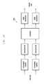
- FIG. 1 is a schematic diagram illustrating to generate a FBMC/OQAM signal. Functions of each module can be easily understood based on subsequent OQAM signal formula expressions. Baseband equivalents of continuous-time multicarrier FBMC/OQAM signal can be expressed by using the following formula (1).
- ( ⁇ ) m,n can represent a frequency-time point.
- a m,n is generated from a real-number modulation signal transmitted on m th subcarrier of the n th symbol that is, a Pulse Amplitude Modulation (PAM) symbol.
- PAM Pulse Amplitude Modulation
- n ⁇ ⁇ ⁇ c m , n _ ⁇ n ⁇ ⁇ is ⁇ ⁇ even ... n ⁇ ⁇ is ⁇ ⁇ odd , ⁇ and ⁇ respectively represent to take the real part and take the imaginary part.
- j represents an imaginary unit, and j m+n represents that real part and imaginary part alternate.
- M is an even number, which represents number of subcarriers.
- Set represents a set of transmitted symbols.
- ⁇ 0 represents an interval between subcarriers.
- g is a prototype filter function, time-domain impulse response length thereof is K times of ⁇ . Subsequently, time-domain waveforms of adjacent (2K ⁇ 1) symbols is partially overlapped. Thus, K is generally referred to as filter overlapping factor.
- g m,n (t) represents an equivalent synthesis filter function for modulating a m,n .
- OQAM symbol rate is 2 times of symbol rate of traditional OFDM.
- CP may be not added to the OQAM. Since OQAM modulation is real number, information taken by each OQAM symbol is half of that of traditional OFDM. That is, signal transmission rate of one OQAM system is the same as that of an OFDM system without CP.
- OQAM real-domain orthogonality is implemented by designing a prototype filter function.
- Inner product of transmitter synthesis filter function and receiver analysis filter function should meet, or approximately meet formula (2) that is, the prototype filter should meet the following requirements.
- ( ⁇ ) represents a complex conjugate.
- ⁇ represents an operation of taking real part.
- ⁇ represents an inter product.
- the inner product is represented by g m,n m′,n′ . It is obvious that pure imaginary part interference is resulted from signals between different sub-carriers and different symbols.
- the originally transmitted real-number signal a m,n is obtained through Perfect Reconstruction (PR), after performing a simple operation to a received signal based on formula (3), by using a receiving Analysis Filter (AF) g m,n *(t) matching with transmitting Synthesis Filter (SF) g m,n (t).
- PR Perfect Reconstruction
- AF Analysis Filter
- SF Synthesis Filter
- ⁇ m,n formula (3) represents a noise item.
- the originally transmitted data is demodulated, after synthesizing complex QAM signal c m, ⁇ umlaut over (n) ⁇ .
- y m,n represents the signal received on the m th subcarrier of the n th symbol.
- channel fading coefficient corresponding to the m th subcarrier of the n th symbol is h m,n signals passing an AF group is represented as follows.
- ⁇ r m , n h m , n ⁇ a m , n + ⁇ ( m ′ , n ′ ) ⁇ ( m , n ) ⁇ ⁇ h m ′ , n ′ ⁇ a m ′ , n ′ ⁇ ⁇ g m ′ , n ′
- the second item in formula (4) is directly related with prototype filter design, which is referred to as intrinsic interference of the FBMC/OQAM system.
- each sub-carrier in the foregoing formula receives interferences of sub-carriers within a limited area around. And such area set is defined as an interference area ⁇ m,n .
- an interference area ⁇ m,n Take into account of prototype filter properties in formula (2), when channel fading coefficient h m,n is a real number, or (m′, n′) ⁇ m,n , and then h m′,n′ ⁇ h m,n .
- intrinsic interference item in formula (4) is a pure imaginary number.
- Transmitted signal a m,n is restored, by using a simple equalization and operation of taking real part in formula (3).
- h n′,n′ represents a channel fading coefficient corresponding to the m′ th sub-carrier of the n′ th symbol.
- intrinsic interference item which is a pure imaginary number originally, generates interferences for signals transmitted by real part.
- ⁇ circumflex over ( ⁇ ) ⁇ m,n ⁇ m,n /h m,n represents an equalized equivalent noise. It can be seen that, when h m′, n′ ⁇ h m,n , interferences of original pure imaginary part is spread to real part, which leads to ICI and ISI. This kind of interferences are not reduced, accompanying with increasing SNR. Subsequently, system generates an error floor in a scene with higher SNR. For a high-speed mobility scene (strong time selective fading) and an environment with strong frequency selectivity, channel coefficients of adjacent sub-carriers and symbols are significantly different. Thus, error floor problem becomes more significant, which can have a severe impact on system link reliability.
- the embodiment provides a method for processing error floor problem, which is resulted from intrinsic interference in a high-speed mobility environment, when processing OQAM modulation DB, accompanying with specific filter parameter setting and system configuration.
- PRB Physical Resource Block
- OQAM system overlapping factor K 4.
- Filter parameter uses PHYDYAS filter. Time-domain response thereof is represented as follows.
- ⁇ g ⁇ ( 0 ) 0
- one PRB is divided into two Resource Blocks (RBs) in the embodiment. These two RBs shares the same time resources. However, the first RB uses first six subcarriers, so as to transmit original data. The second RB uses latter six subcarriers, so as to transmit conjugate of original data. That is, subcarriers #1 ⁇ #6 transmits QAM symbols 1,n ⁇ 6,n , while subcarriers #7 ⁇ #12 transmits 1,n * ⁇ 6,n *.
- RBs Resource Blocks
- DB 2 is obtained by transmission of an adjacent subcarrier group of the subcarrier group transmitting DB 1 .
- FIG. 2 The schematic diagram 200 about the time frequency symbol after OQAM modulation is shown in FIG. 2 .
- adjacent PAM symbols is respectively modulated into real part and imaginary part of a subcarrier, to guarantee real-number domain orthogonality of OQAM system.
- block diagram 300 of a transmitter for transmitting a signal is as shown in FIG. 3 , which includes as follows.
- Transmitter maps 305 an original DB including at least one symbol to a first RB, preprocesses 310 the original DB, and maps the preprocessed original DB to a second RB.
- the transmitter then modulates 315 data of the first and second RBs by using FBMC modulation, and transmits 320 the data modulated.
- channel frequency selectivity is weaker, that is, intrinsic interference of the OQAM system basically has no impact on frequency-domain real part orthogonality. That is, after taking the real part, residual ICI can be ignored.
- d m,n a represents an equalization coefficient needed by real part signal a m,n .
- I m,n a represents a real number, which denotes the ICI resulted from intrinsic interference of the FBMC/OQAM system.
- I m,n b represents a complex number, which denotes ISI resulted from intrinsic interference of the FBMC/OQAM system.
- ⁇ m,n a represents an equalized equivalent noise.
- channel frequency selectivity is weaker
- d m′,n a d m,n a
- real part signal a m,n can be simply estimated as follows. â m,n + ⁇ ( ⁇ circumflex over (r) ⁇ m,n a + ⁇ circumflex over (r) ⁇ m′,n a )/2 ⁇ (7)
- FIG. 4 is a schematic diagram 400 illustrating a method for a receiver to process received signals, in accordance with an embodiment of the present disclosure, which includes as follows. After receiving a DB, receiver demodulates 405 the DB by using a FBMC-based demodulation mode, equalizes 410 each demodulated symbol, and finally combines 415 equalized DBs based on DB size predefined by system.
- data transmission sequence in DB 2 is the same as that in DB 1 .
- some residual ISI exists in symbols at the edge of each DB, since these edge data symbols receive different interferences in different DBs.
- data transmission sequence in DB 2 is contrary to that in DB 1 . That is, subcarriers # ⁇ #12 is used to transmit complex conjugate of symbols transmitted on subcarriers # ⁇ #1 in sequence.
- interferences received by symbols respectively transmitted on subcarriers #6 and #7 come from the same symbol. Subsequently, the interferences can be totally eliminated by using formulas (8) and (9).
- a same sequence is used to transmit data of DB 1 and DB 2 in solution 1. Meanwhile, a reverse transmission sequence is used to transmit the data of DB 1 and DB 2 in solution 2.
- FIG. 5 is a schematic diagram 500 illustrating preprocessing of a transmitter, when solution 2 of the present disclosure is used.
- the system employs a Quadrature Phase Shift Keying (QPSK) modulation.
- QPSK Quadrature Phase Shift Keying
- subcarriers # ⁇ #12 thereof is used to repeatedly transmit data already transmitted on subcarriers #1 ⁇ #6.
- Data rate of the OQAM system is the same as data rate achievable in the embodiment.
- FIG. 6 is a schematic diagram 600 illustrating processing of a transmitter in a comparative object.
- FIG. 7 illustrates BER curves 400 of two solutions under such circumstances.
- solution 1 and solution 2 respectively represent the following scenes.
- Symbol sequence of subcarriers #7 ⁇ #12 is the same as that of subcarriers #1 ⁇ #6 in solution 1.
- Symbol sequence of subcarriers #7 ⁇ #12 is contrary to that of subcarriers #1 ⁇ #6 in solution 2.
- Different solutions possess similar performance with lower SNR. Due to high user mobility speed, intrinsic interference of OQAM system leads to serious ISI, such that an error floor with BER 10 ⁇ 2 occurs in a scene with higher SNR by using the comparative solution, which will have a serious impact on system error performance.
- solution 1 effectively eliminates ISI, and can significantly reduce error floor resulted from the ISI.
- Solution 2 can further eliminate ISI resulted from intrinsic interference, such that error floor will still not occur after SNR of the BER curve is greater than 20 dB, which can prove that error performance achieved by the embodiment under such channel condition is far better than that of the
- FIG. 8 is a schematic diagram 800 illustrating BER comparisons of different solutions hi the EPA channel, in accordance with an embodiment of the present disclosure.
- the EPA channel has a certain frequency selectivity, however there is little difference between channel coefficients of adjacent subcarriers, which has a small impact on system.
- the solution put forward by the embodiment can still effectively eliminate error floor, which is resulted from intrinsic interference of time selective fading channel.
- FIG. 9 is a schematic diagram 900 illustrating comparisons of error performances of various solutions, when user mobility speed is 300 km/h in an ETU channel.
- frequency selectivity of ETU channel is more obvious, and there is greater difference between channel coefficients of adjacent subcarriers.
- System performance is further reduced resulted from strong frequency selectivity, meanwhile performance of the method put forward by the embodiment is also affected.
- the solution put forward by the embodiment particularly solution 2
- the preprocessing performed to original DB includes as follows. Take an opposite number for each symbol of even OQAM symbols or odd OQAM symbols of the original DB.
- a method for performing a conjugate to original DB and transmitting on adjacent subcarrier group is used.
- Such method possesses obvious advantages, when resisting a strong time selectivity fading channel, which can also lower error floor resulted from the ISI.
- such method no longer possesses advantages in a strong frequency selectivity channel.
- resource allocation modes of the first RB and second RB should be modified firstly.
- two RBs use the same frequency resources.
- the first RB uses first 14 symbols, which is used to transmit original data
- the second RB uses latter 14 symbols, which is used to transmit preprocessed DBs.
- the preprocessing method is as follows. Data transmitted on odd subcarriers remains unchanged. Take an opposite number for data transmitted on even subcarriers.
- a schematic diagram 1000 illustrating a method for transmitter to preprocess transmitted data in the embodiment can be as shown in FIG. 10 .
- c m,n represents symbol of time frequency point (m, n) after executing OQAM modulation.
- ⁇ m,n represents an estimated value of c m,n .
- ⁇ circumflex over (r) ⁇ m,n and ⁇ circumflex over (r) ⁇ m,n′ respectively represent a symbol of equalized time frequency points (m, n) and (m, n′). It should be noted that time frequency points (m, n) and (m, n′) are respectively located in DB 1 and DB 2 . Information transmitted on (m, n) and (m, n′) is the same.
- the preprocessing method in the foregoing example is as follows. Data transmitted on odd subcarriers remains unchanged. However, take an opposite number for data transmitted on even subcarriers. In practical applications, a reverse preprocessing method is also used. That is, data transmitted on even subcarriers remains unchanged. Take an opposite number for data transmitted on odd subcarriers. Correspondingly, formula (11) is used to combine symbols transmitted on odd subcarriers, when executing combination. Formula (10) is used to combine symbols transmitted on even subcarriers.
- Effectiveness for strong frequency selective fading channel achieved by the embodiment will be described, by using simulation result.
- System employs the QPSK modulation.
- data transmitted in DB 2 is totally the same as data transmitted in DB 1 , without executing any preprocessing.
- the channel module employs an ETU module with strong frequency selectivity.
- FIG. 11 is a schematic diagram 1100 illustrating BER performance comparisons in different solutions by using the ETU channel module, when receiver is static.
- the embodiment can significantly reduce error floor.
- error performances of these two solutions are similar.
- the solution provided by the embodiment possesses a faster BER descent speed.
- advantageous 6 dB is achieved by the solution of the embodiment.
- the first and second embodiments respectively provide a solution for strong time selective fading and strong frequency selective fading.
- the embodiment will provide a solution of the present disclosure, when foregoing two kinds of fading exist simultaneously and respectively fading strength is strong.
- the following two methods can be combined. Take conjugate of original DB in the first embodiment. Take an opposite number of the original DB every other subcarrier in the second embodiment. The method is briefly described as follows.
- the resource allocation mode similar to that in the second embodiment can be used. That is, the first RB and the second RB employ the same frequency resources.
- the first RB uses first 14 symbols of each PRB, which is used to transmit the original DB.
- the second RB uses latter 14 symbols of each PRB, which is used to transmit preprocessed DBs.
- When executing the preprocessing firstly perform a conjugate to original DB, and then take an opposite number of each symbol on even subcarriers.
- a schematic diagram 1200 illustrating transmitter to preprocess data to be transmitted in the embodiment is shown in FIG. 12 .
- sequence of foregoing preprocessing can be changed. That is, firstly take an opposite number of each symbol of even subcarriers, and then take a conjugate of the result. At this time, corresponding combination operations are also necessary to be swapped. That is, for real part of each symbol transmitted on odd subcarriers and imaginary part of each symbol transmitted on even subcarriers, formula (11) is used to execute combination and data restoring. For imaginary part of each symbol transmitted on odd subcarriers and real part of each symbol transmitted on even subcarriers, formula (10) is used to execute combination and data restoring.
- the first RB and the second RB use the same time resources.
- the first RB uses first 6 subcarriers of each PRB, which is used to transmit the original DB.
- the second RB uses latter 6 subcarriers of each PRB, which is used to transmit preprocessed DBs.
- the preprocessing mode can be as follows. Firstly, perform a conjugate to the original DB. And then, take an opposite number to data of even subcarriers.
- Combination operation of receiver is as follows. For real part of each symbol transmitted on odd subcarriers and imaginary part of each symbol transmitted on even subcarriers, formula (8) is used to execute combination and data restoring.
- formula (10) is used to execute combination and data restoring. It should be noted that preprocessing sequence of DB can be swapped, which will not be repeated here.
- the embodiment provides applications of the present disclosure in a multi-antenna system. Compared with a single antenna system, for inter-link interference in the multi-antenna system, preceding executed by the transmitter and equalization operations executed by the receiver are even more complicated. However, the solution provided by the present disclosure is still be applicable to the multi-antenna system.
- FIG. 13 and FIG. 14 are respectively schematic diagrams 1300 , 1400 illustrating transmitter and receiver in a multi-antenna system, in accordance with embodiments of the present disclosure.
- a precoding module is necessary to be added between DB preprocessing and OQAM modulation, by a transmitter hi a multi-antenna system, so as to reduce or eliminate inter-link interference.
- the precoding operations perform the same processes to symbols of same time frequency resources, time frequency structure after DB preprocessing will not be affected.
- Receiver structure is similar to that of the single-antenna system.
- the solution provided by the embodiment is still effective in the multi-antenna system, which will be described with simulation.
- transmitter is not execute preceding (or preceding matrix is a unit matrix).
- the receiver uses a Minimum Mean Square Error (MMSE) equalization algorithm.
- MMSE Minimum Mean Square Error
- Channel module respectively uses a single-path channel and an ETU channel. Receiver mobility speed is 300 km/h. It can be seen that, the channel possesses strong time selectivity.
- the transmitter uses a solution similar to that in the first embodiment, that is, to preprocess the original DB.
- the preprocessing schematic diagram can be shown in FIG. 2 .
- the receiver uses formulas (8) and (9) to perform combination operations to received signals.
- FIG. 15 is a schematic diagram 1500 illustrating BER comparisons in different solutions of a single-path scene, in accordance with an embodiment of the present disclosure. It can be seen that, the solution in the embodiment can still significantly reduce ISI, which is resulted from intrinsic interference of FBMC/OQAM system. When the SNR is low, two solutions can have similar error performances. Accompanying with increasing of SNR, BER descent speed of the comparative object is reduced gradually, and an error floor occurs around 16 dB. However, by using the solution of the embodiment, even if in a scene with higher SNR, rapid BER descent speed is maintained. It is demonstrated that the solution can reduce, or even eliminate the error floor, and improve system link reliability.
- FIG. 16 is a schematic diagram 1600 illustrating BER comparisons in different solutions in the ETU channel, when receiver mobility speed is 300 km/h. Strong frequency selectivity of the ETU channel leads to further deterioration of system performance. However, by using the solution of the embodiment, occurrence of error floor is still effectively delayed, error floor is reduced, and link reliability can be unproved in a scene with a higher SNR.
- the embodiment provides a solution about dynamic preprocessing of transmitter, when channel changes. Since actual transmission environment changes, accompanying with changes of environment, particularly in a high-speed mobility environment, channel fading also changes accompanying with significant location change. Thus, preprocessing performed to original DB by the transmitter should also change therewith. Specifically speaking, original DB size, resource allocation mode and data processing mode also change, accompanying with channel change. Besides, based on channel adaptive preprocessing mode, adaptability to actual scenes of the solution provided by the present disclosure can also be improved.
- FIG. 17 is a flowchart 1700 illustrating an adaptive transmitter preprocessing, in accordance with an embodiment of the present disclosure.
- Resource allocation mode and preprocessing mode are selected, by determining whether channel time selectivity is strong, or frequency selectivity is strong. Specifically speaking, when channel time selectivity is strong, ISI resulted from intrinsic interference is even worse, frequency domain repeated mode is selected to allocate resources, and a mode to take a conjugate for original DB is selected to execute preprocessing. When channel frequency selectivity is strong, ICI resulted from intrinsic interference is even worse, time domain repeated mode is selected to allocate resources, and another mode to take an opposite number of subcarrier symbols every other line is selected to execute preprocessing.
- the frequency domain repeated mode is firstly selected to allocate resources, and the preprocessing is executed by combining two modes, that is, take an opposite number of subcarrier symbols every other line and take a conjugate.
- whether the channel time selectivity is strong or weak is determined by time selective index value.
- the time selective index value is coherent time, Doppler shift extension, and so on.
- a set first condition e.g., when channel coherent time is less than a preset threshold, when channel Doppler shift extension is greater than a preset threshold, or a user mobility speed is greater than a preset threshold
- determine that the time selectivity is strong e.g., when channel coherent time is less than a preset threshold, when channel Doppler shift extension is greater than a preset threshold, or a user mobility speed is greater than a preset threshold
- determine that the time selectivity is strong e.g., when channel coherent time is less than a preset threshold, when channel Doppler shift extension is greater than a preset threshold, or a user mobility speed is greater than a preset threshold
- determine that the time selectivity is strong e.g., when channel coherent time is less than a preset threshold, when channel Doppler shift extension is greater than a
- the frequency selectivity index value meets a set second condition (e.g., when channel coherent bandwidth is less than a preset threshold, or channel delay extension is greater than a preset threshold), determine that frequency selectivity is strong.
- a set second condition e.g., when channel coherent bandwidth is less than a preset threshold, or channel delay extension is greater than a preset threshold
- DB size is selected based on channel change speed. Specifically speaking, when channel change speed is faster, smaller DB is used. When channel change speed is lower, larger DB is used.
- a preferred mode for selecting the size of the original DB can be as follows. Classify the channel change speeds into different groups. Each group corresponds to a size of an original DB. And make a look-up table based on such corresponding relationship. Select an appropriate size of an original DB from the look-up table, based on an actual channel change speed. Since the channel change speed is directly related with strength of channel time selectivity or channel frequency selectivity, the channel change speed is measured by using the channel time selective index or the channel frequency selective index.
- the DB size is also determined by a size of a data symbol block to be transmitted. That is, adjust the size of the repeated DB (that is, the original DB) based on the size of the data symbol block to be transmitted, such that the size of the data symbol block to be transmitted is an integer multiple of the size of the repeated DB (that is, the original DB).
- the receiver estimates the time selectivity and the frequency selectivity based on a reference signal received from the transmitter, and feeds back a corresponding index value.
- the transmitter determines the resource allocation mode, the mapping order of preprocessed DBs and DB size based on the channel selective index fed back by the receiver.
- the specific blocks are as follows.
- the transmitter selects the resource allocation mode based on the channel selective index.
- select to allocate resources repeatedly in a frequency domain continuously monitor the channel frequency selectivity, select the employed DB size and whether to employ an inverse order of mapping based on the strength of the frequency selectivity.
- the receiver can also select an appropriate resource allocation mode, the DB size and the mapping order based on the channel estimation result, and feed back the selected resource allocation mode, the DB size and the mapping order.
- the feedback can be implemented after searching a look-up table, that is, only the index is fed back.
- the transmitter can learn the preprocessing mode by using the index.
- the mode of searching a look-up table respectively make a look-up table for the resource allocation mode, the DB size and the mapping order, and feed back three indexes. Alternatively, make one look-up table by synthesizing each mode, and feed back one index.
- the transmitter informs the receiver about the preprocessing mode by using a downlink control channel or a downlink shared channel.
- the downlink control channel When using the downlink control channel to inform the receiver about the preprocessing mode, insert a new field indicator in downlink control information.
- the new field indicator is used to indicate the resource allocation mode, the DB size and the mapping order.
- the new field indicator can be the resource allocation mode indicator, the DB size indicator and the mapping order indicator.
- the foregoing indication employs a mode of searching a look-up table. That is, the transmitter transmits an index to the receiver. The receiver determines the preprocessing mode by searching a look-up table with the index.
- a look-up table When employing the mode of searching a look-up table, respectively make a look-up table for the resource allocation mode, the DB size and the mapping order, and transmit three indexes. Alternatively, make one look-up table by synthesizing each mode, and transmit one index.
- a corresponding field In addition to the downlink control channel, a corresponding field can also be transmitted in the downlink shared channel.
- Transmitter structure 1800 is referred to FIG. 18 .
- the transmitter includes a mapping module 1805 , a modulating module 1810 and a transmitting module 1815 .
- the mapping module is to map an original DB including at least one symbol to a first RB, preprocess the original DB, and map the preprocessed original DB to a second RB.
- the modulating module is to modulate data of the first RB and the second RB, by using a FBMC modulation.
- the transmitting module is to transmit the data modulated.
- Receiver structure 1900 is shown in FIG. 10 .
- the receiver includes a receiving module 1905 , a demodulating module 1910 , an equalizing module 1920 and a postprocessing module 1925 .
- the receiving module is to receive a DB.
- the demodulating module is to demodulate the received DB, by using a FBMC-based demodulation mode.
- the equalizing module is to equalize each demodulated symbol.
- the postprocessing module is to perform a postprocessing to an equalized DB, based on a set DB size.
Landscapes
- Engineering & Computer Science (AREA)
- Signal Processing (AREA)
- Computer Networks & Wireless Communication (AREA)
- Mobile Radio Communication Systems (AREA)
- Physics & Mathematics (AREA)
- Discrete Mathematics (AREA)
- General Physics & Mathematics (AREA)
- Mathematical Physics (AREA)
- Digital Transmission Methods That Use Modulated Carrier Waves (AREA)
Abstract
Description
â m,n =
{circumflex over (r)} m,n a =a m,n +jd m,n a I m,n a +d m,n a I m,n b+ηm,n a (5)
{circumflex over (r)} m′,n a =a m,n +jd m′,n a I m′,n a −d m′,n a I m′,n b+ηm′,n a (6)
â m,n+
{circumflex over (b)} m,n=
ĉ m,n=
ĉ m,n=
Claims (20)
Applications Claiming Priority (6)
| Application Number | Priority Date | Filing Date | Title |
|---|---|---|---|
| CN201510520043 | 2015-08-21 | ||
| CN201510520043.7 | 2015-08-21 | ||
| CN201510520043 | 2015-08-21 | ||
| CN201510848630.9 | 2015-11-27 | ||
| CN201510848630 | 2015-11-27 | ||
| CN201510848630.9A CN106470180B (en) | 2015-08-21 | 2015-11-27 | Signal transmission method, reception method and device based on filter bank multi-carrier modulation |
Publications (2)
| Publication Number | Publication Date |
|---|---|
| US20170054539A1 US20170054539A1 (en) | 2017-02-23 |
| US10128995B2 true US10128995B2 (en) | 2018-11-13 |
Family
ID=58100471
Family Applications (1)
| Application Number | Title | Priority Date | Filing Date |
|---|---|---|---|
| US15/236,383 Active 2036-11-19 US10128995B2 (en) | 2015-08-21 | 2016-08-12 | Filter bank multicarrier modulation-based signal transmitting method, signal receiving method and device |
Country Status (2)
| Country | Link |
|---|---|
| US (1) | US10128995B2 (en) |
| WO (1) | WO2017034185A1 (en) |
Families Citing this family (4)
| Publication number | Priority date | Publication date | Assignee | Title |
|---|---|---|---|---|
| CN107733830B (en) * | 2016-08-12 | 2021-12-10 | 中兴通讯股份有限公司 | Method, device and system for generating multi-carrier signal |
| TWI722689B (en) * | 2019-11-29 | 2021-03-21 | 財團法人工業技術研究院 | Detector and interference cancellation method for spatial multiplexing filter bank multicarrier with offset quadrature amplitude modulation |
| CN114826838B (en) * | 2022-05-19 | 2023-04-25 | 南京信息工程大学 | Channel estimation algorithm of FBMC radar communication integrated system based on preamble sequence |
| CN116192576B (en) * | 2023-03-02 | 2023-08-11 | 哈尔滨工程大学 | PSRO prototype filter for FBMC system against frequency selective fading |
Citations (14)
| Publication number | Priority date | Publication date | Assignee | Title |
|---|---|---|---|---|
| US20080019305A1 (en) * | 2006-07-20 | 2008-01-24 | Armin Dekorsy | Allocating channels in multi-user or multi-service real-time transmissions of wireless packet data |
| US20090122853A1 (en) * | 2007-11-12 | 2009-05-14 | Acorn Technologies, Inc. | Channel tracking methods for subspace equalizers |
| US20090196249A1 (en) * | 2006-06-19 | 2009-08-06 | Ntt Docomo, Inc. | Base station, user device, and method used in mobile communication system |
| US20090213948A1 (en) * | 2005-08-23 | 2009-08-27 | Jianglei Ma | Adaptive two-dimensional channel interpolation |
| US20100246498A1 (en) * | 2006-05-25 | 2010-09-30 | Electronics And Telecommunications Research Institute | Method of constructing resource allocation map for mobile communication system |
| US20110164526A1 (en) * | 2008-09-04 | 2011-07-07 | Bando Chemical Industries Ltd | Method and apparatus for uplink signal transmission and channel estimation in wireless access network |
| US20140056220A1 (en) * | 2012-08-23 | 2014-02-27 | Interdigital Patent Holdings, Inc. | Method and apparatus for performing device-to-device discovery |
| CN103825862A (en) | 2014-03-07 | 2014-05-28 | 华中科技大学 | Filter bank multi-carrier method based on offset quadrature amplitude modulation |
| WO2014085710A1 (en) | 2012-11-29 | 2014-06-05 | Interdigital Patent Holdings, Inc. | Reduction of spectral leakage in an ofdm system |
| US20140233437A1 (en) * | 2013-02-19 | 2014-08-21 | Futurewei Technologies, Inc. | Frame Structure for Filter Bank Multi-Carrier (FBMC) Waveforms |
| US20140286384A1 (en) * | 2013-03-19 | 2014-09-25 | Fundació Centre Tecnològic De Telecomunicacions De Catalunya | Method for equalizing filterbank multicarrier (fbmc)modulations |
| EP2819478A1 (en) | 2013-06-27 | 2014-12-31 | Alcatel Lucent | A method for allocating radio resources, and a base station and a user terminal therefor |
| WO2016156580A1 (en) | 2015-04-01 | 2016-10-06 | Ntt Docomo, Inc. | Transmit diversity from orthogonal design for fbmc/oqam |
| US20170332376A1 (en) * | 2014-11-24 | 2017-11-16 | Telefonaktiebolaget Lm Ericsson (Publ) | Method and Device for Transmission and Reception of Time-Frequency Resources |
-
2016
- 2016-08-10 WO PCT/KR2016/008779 patent/WO2017034185A1/en not_active Ceased
- 2016-08-12 US US15/236,383 patent/US10128995B2/en active Active
Patent Citations (15)
| Publication number | Priority date | Publication date | Assignee | Title |
|---|---|---|---|---|
| US20090213948A1 (en) * | 2005-08-23 | 2009-08-27 | Jianglei Ma | Adaptive two-dimensional channel interpolation |
| US20100246498A1 (en) * | 2006-05-25 | 2010-09-30 | Electronics And Telecommunications Research Institute | Method of constructing resource allocation map for mobile communication system |
| US20090196249A1 (en) * | 2006-06-19 | 2009-08-06 | Ntt Docomo, Inc. | Base station, user device, and method used in mobile communication system |
| US20080019305A1 (en) * | 2006-07-20 | 2008-01-24 | Armin Dekorsy | Allocating channels in multi-user or multi-service real-time transmissions of wireless packet data |
| US20090122853A1 (en) * | 2007-11-12 | 2009-05-14 | Acorn Technologies, Inc. | Channel tracking methods for subspace equalizers |
| US20110164526A1 (en) * | 2008-09-04 | 2011-07-07 | Bando Chemical Industries Ltd | Method and apparatus for uplink signal transmission and channel estimation in wireless access network |
| US20140056220A1 (en) * | 2012-08-23 | 2014-02-27 | Interdigital Patent Holdings, Inc. | Method and apparatus for performing device-to-device discovery |
| WO2014085710A1 (en) | 2012-11-29 | 2014-06-05 | Interdigital Patent Holdings, Inc. | Reduction of spectral leakage in an ofdm system |
| US20150304146A1 (en) * | 2012-11-29 | 2015-10-22 | Interdigital Patent Holdings, Inc. | Resource block based multicarrier modulations for agile spectrum |
| US20140233437A1 (en) * | 2013-02-19 | 2014-08-21 | Futurewei Technologies, Inc. | Frame Structure for Filter Bank Multi-Carrier (FBMC) Waveforms |
| US20140286384A1 (en) * | 2013-03-19 | 2014-09-25 | Fundació Centre Tecnològic De Telecomunicacions De Catalunya | Method for equalizing filterbank multicarrier (fbmc)modulations |
| EP2819478A1 (en) | 2013-06-27 | 2014-12-31 | Alcatel Lucent | A method for allocating radio resources, and a base station and a user terminal therefor |
| CN103825862A (en) | 2014-03-07 | 2014-05-28 | 华中科技大学 | Filter bank multi-carrier method based on offset quadrature amplitude modulation |
| US20170332376A1 (en) * | 2014-11-24 | 2017-11-16 | Telefonaktiebolaget Lm Ericsson (Publ) | Method and Device for Transmission and Reception of Time-Frequency Resources |
| WO2016156580A1 (en) | 2015-04-01 | 2016-10-06 | Ntt Docomo, Inc. | Transmit diversity from orthogonal design for fbmc/oqam |
Non-Patent Citations (2)
| Title |
|---|
| Supplementary European Search Report dated Aug. 6, 2018 in connection with European Patent Application No. 16 83 9474. |
| The International Searching Authority, "International Search Report," International Application No. PCT /KR2016/008779, Nov. 16, 2016, 3 pages, publisher the ISA/KR, International Application Division, Korean Intellectual Property Office, Daejeon, Republic of Korea. |
Also Published As
| Publication number | Publication date |
|---|---|
| US20170054539A1 (en) | 2017-02-23 |
| WO2017034185A1 (en) | 2017-03-02 |
Similar Documents
| Publication | Publication Date | Title |
|---|---|---|
| US9960887B2 (en) | Method and apparatus of signal transmission and reception in a filter bank multiple carrier system | |
| US10476544B2 (en) | Signal transmission and receiving method, system and apparatus based on filter bank | |
| US10063401B2 (en) | Communication method and apparatus based on a filter bank multi-carrier modulation | |
| US10484216B2 (en) | Filtering-based signal transmission and receiving methods and corresponding transmitter and receiver | |
| US10027520B2 (en) | Method and apparatus for generating, transmitting and receiving signals based on filter bank in wireless communication system | |
| US8891662B2 (en) | Reference symbol structure for DFT spread OFDM system | |
| US7929416B2 (en) | Receiving a pilot design and channel estimation | |
| CN107306238B (en) | Method for receiving and transmitting carrier modulation signals, and corresponding receiver and transmitter | |
| CN107222442B (en) | Signal transmitting and receiving method and device in carrier modulation system based on filtering | |
| US10594453B2 (en) | Method and apparatus for transmitting and receiving preamble based reference signal | |
| CN105991490B (en) | Signal sending and receiving method, system and device based on filter bank | |
| WO2009070983A1 (en) | Method, system and apparatus for signal generation and message transmission in broadband wireless communications | |
| US10128995B2 (en) | Filter bank multicarrier modulation-based signal transmitting method, signal receiving method and device | |
| CN105847209B (en) | Communication method and device based on filter bank multi-carrier modulation | |
| US12476858B2 (en) | Methods and apparatus for using a phase tracking reference signal with a single carrier waveform | |
| EP3338421B1 (en) | Filter bank multicarrier modulation-based signal transmitting method, signal receiving method and device | |
| US20250150305A1 (en) | Method and apparatus for modulation in communication system | |
| CN106302301A (en) | FBMC signal based on complex modulation send and receive method and device | |
| WO2012109930A1 (en) | Method, device, and system for transmitting baseband data | |
| Ameigeiras et al. | Physical layer technologies in 5G | |
| Singh | Channel Estimation and Receiver Design for FBMC-OQAM and OTFS Modulation Schemes | |
| Luo | Low-PAPR Multiplexing of Data and Pilots |
Legal Events
| Date | Code | Title | Description |
|---|---|---|---|
| AS | Assignment |
Owner name: SAMSUNG ELECTRONICS CO., LTD, KOREA, REPUBLIC OF Free format text: ASSIGNMENT OF ASSIGNORS INTEREST;ASSIGNORS:QIAN, CHEN;SUN, PENGFEI;YU, BIN;AND OTHERS;SIGNING DATES FROM 20160801 TO 20160807;REEL/FRAME:039426/0543 |
|
| STCF | Information on status: patent grant |
Free format text: PATENTED CASE |
|
| MAFP | Maintenance fee payment |
Free format text: PAYMENT OF MAINTENANCE FEE, 4TH YEAR, LARGE ENTITY (ORIGINAL EVENT CODE: M1551); ENTITY STATUS OF PATENT OWNER: LARGE ENTITY Year of fee payment: 4 |
|
| MAFP | Maintenance fee payment |
Free format text: PAYMENT OF MAINTENANCE FEE, 8TH YEAR, LARGE ENTITY (ORIGINAL EVENT CODE: M1552); ENTITY STATUS OF PATENT OWNER: LARGE ENTITY Year of fee payment: 8 |