US10126419B2 - Method for the network initialization of a network for the radio location of objects within a limited space - Google Patents
Method for the network initialization of a network for the radio location of objects within a limited space Download PDFInfo
- Publication number
- US10126419B2 US10126419B2 US15/490,998 US201715490998A US10126419B2 US 10126419 B2 US10126419 B2 US 10126419B2 US 201715490998 A US201715490998 A US 201715490998A US 10126419 B2 US10126419 B2 US 10126419B2
- Authority
- US
- United States
- Prior art keywords
- reference nodes
- information
- network
- initialization
- chain
- Prior art date
- Legal status (The legal status is an assumption and is not a legal conclusion. Google has not performed a legal analysis and makes no representation as to the accuracy of the status listed.)
- Expired - Fee Related
Links
- 238000000034 method Methods 0.000 title claims abstract description 102
- 230000006854 communication Effects 0.000 claims abstract description 72
- 238000004891 communication Methods 0.000 claims abstract description 70
- 230000004807 localization Effects 0.000 claims description 29
- 238000005259 measurement Methods 0.000 claims description 27
- 238000012790 confirmation Methods 0.000 claims description 15
- 230000004044 response Effects 0.000 claims description 15
- 238000004590 computer program Methods 0.000 claims description 6
- 230000000644 propagated effect Effects 0.000 claims description 5
- 238000013500 data storage Methods 0.000 claims description 3
- 230000009466 transformation Effects 0.000 claims description 3
- 230000001902 propagating effect Effects 0.000 claims description 2
- 230000008569 process Effects 0.000 description 52
- 241000723353 Chrysanthemum Species 0.000 description 14
- 235000005633 Chrysanthemum balsamita Nutrition 0.000 description 14
- 230000015572 biosynthetic process Effects 0.000 description 10
- 238000005516 engineering process Methods 0.000 description 6
- 238000012545 processing Methods 0.000 description 6
- 230000007480 spreading Effects 0.000 description 6
- 238000003892 spreading Methods 0.000 description 6
- 230000001360 synchronised effect Effects 0.000 description 6
- 230000008901 benefit Effects 0.000 description 4
- 230000005540 biological transmission Effects 0.000 description 4
- 238000003745 diagnosis Methods 0.000 description 4
- 238000012546 transfer Methods 0.000 description 4
- 230000008859 change Effects 0.000 description 3
- 238000010276 construction Methods 0.000 description 3
- 238000010586 diagram Methods 0.000 description 3
- 208000034972 Sudden Infant Death Diseases 0.000 description 2
- 206010042440 Sudden infant death syndrome Diseases 0.000 description 2
- 230000009471 action Effects 0.000 description 2
- 238000004364 calculation method Methods 0.000 description 2
- 230000000694 effects Effects 0.000 description 2
- 230000006870 function Effects 0.000 description 2
- 230000008521 reorganization Effects 0.000 description 2
- 230000008054 signal transmission Effects 0.000 description 2
- 230000001960 triggered effect Effects 0.000 description 2
- 229910000831 Steel Inorganic materials 0.000 description 1
- 238000013459 approach Methods 0.000 description 1
- 230000000739 chaotic effect Effects 0.000 description 1
- 230000003111 delayed effect Effects 0.000 description 1
- 238000001514 detection method Methods 0.000 description 1
- 238000009826 distribution Methods 0.000 description 1
- 238000010348 incorporation Methods 0.000 description 1
- 238000009776 industrial production Methods 0.000 description 1
- 238000007726 management method Methods 0.000 description 1
- 238000004519 manufacturing process Methods 0.000 description 1
- 239000000203 mixture Substances 0.000 description 1
- 238000012986 modification Methods 0.000 description 1
- 230000004048 modification Effects 0.000 description 1
- 238000012544 monitoring process Methods 0.000 description 1
- 238000012913 prioritisation Methods 0.000 description 1
- 239000000047 product Substances 0.000 description 1
- 238000009418 renovation Methods 0.000 description 1
- 230000000717 retained effect Effects 0.000 description 1
- 230000002441 reversible effect Effects 0.000 description 1
- 230000011218 segmentation Effects 0.000 description 1
- 238000001228 spectrum Methods 0.000 description 1
- 239000010959 steel Substances 0.000 description 1
- 239000013589 supplement Substances 0.000 description 1
- 238000012360 testing method Methods 0.000 description 1
- MHRLWUPLSHYLOK-UHFFFAOYSA-N thiomorpholine-3,5-dicarboxylic acid Chemical compound OC(=O)C1CSCC(C(O)=O)N1 MHRLWUPLSHYLOK-UHFFFAOYSA-N 0.000 description 1
- 238000013024 troubleshooting Methods 0.000 description 1
Images




Classifications
-
- G—PHYSICS
- G01—MEASURING; TESTING
- G01S—RADIO DIRECTION-FINDING; RADIO NAVIGATION; DETERMINING DISTANCE OR VELOCITY BY USE OF RADIO WAVES; LOCATING OR PRESENCE-DETECTING BY USE OF THE REFLECTION OR RERADIATION OF RADIO WAVES; ANALOGOUS ARRANGEMENTS USING OTHER WAVES
- G01S13/00—Systems using the reflection or reradiation of radio waves, e.g. radar systems; Analogous systems using reflection or reradiation of waves whose nature or wavelength is irrelevant or unspecified
- G01S13/02—Systems using reflection of radio waves, e.g. primary radar systems; Analogous systems
- G01S13/06—Systems determining position data of a target
- G01S13/46—Indirect determination of position data
-
- H—ELECTRICITY
- H04—ELECTRIC COMMUNICATION TECHNIQUE
- H04L—TRANSMISSION OF DIGITAL INFORMATION, e.g. TELEGRAPHIC COMMUNICATION
- H04L12/00—Data switching networks
- H04L12/28—Data switching networks characterised by path configuration, e.g. LAN [Local Area Networks] or WAN [Wide Area Networks]
- H04L12/40—Bus networks
-
- G—PHYSICS
- G01—MEASURING; TESTING
- G01S—RADIO DIRECTION-FINDING; RADIO NAVIGATION; DETERMINING DISTANCE OR VELOCITY BY USE OF RADIO WAVES; LOCATING OR PRESENCE-DETECTING BY USE OF THE REFLECTION OR RERADIATION OF RADIO WAVES; ANALOGOUS ARRANGEMENTS USING OTHER WAVES
- G01S1/00—Beacons or beacon systems transmitting signals having a characteristic or characteristics capable of being detected by non-directional receivers and defining directions, positions, or position lines fixed relatively to the beacon transmitters; Receivers co-operating therewith
- G01S1/02—Beacons or beacon systems transmitting signals having a characteristic or characteristics capable of being detected by non-directional receivers and defining directions, positions, or position lines fixed relatively to the beacon transmitters; Receivers co-operating therewith using radio waves
- G01S1/04—Details
-
- G—PHYSICS
- G01—MEASURING; TESTING
- G01S—RADIO DIRECTION-FINDING; RADIO NAVIGATION; DETERMINING DISTANCE OR VELOCITY BY USE OF RADIO WAVES; LOCATING OR PRESENCE-DETECTING BY USE OF THE REFLECTION OR RERADIATION OF RADIO WAVES; ANALOGOUS ARRANGEMENTS USING OTHER WAVES
- G01S1/00—Beacons or beacon systems transmitting signals having a characteristic or characteristics capable of being detected by non-directional receivers and defining directions, positions, or position lines fixed relatively to the beacon transmitters; Receivers co-operating therewith
- G01S1/02—Beacons or beacon systems transmitting signals having a characteristic or characteristics capable of being detected by non-directional receivers and defining directions, positions, or position lines fixed relatively to the beacon transmitters; Receivers co-operating therewith using radio waves
- G01S1/08—Systems for determining direction or position line
-
- H—ELECTRICITY
- H04—ELECTRIC COMMUNICATION TECHNIQUE
- H04L—TRANSMISSION OF DIGITAL INFORMATION, e.g. TELEGRAPHIC COMMUNICATION
- H04L41/00—Arrangements for maintenance, administration or management of data switching networks, e.g. of packet switching networks
- H04L41/12—Discovery or management of network topologies
-
- H—ELECTRICITY
- H04—ELECTRIC COMMUNICATION TECHNIQUE
- H04L—TRANSMISSION OF DIGITAL INFORMATION, e.g. TELEGRAPHIC COMMUNICATION
- H04L41/00—Arrangements for maintenance, administration or management of data switching networks, e.g. of packet switching networks
- H04L41/14—Network analysis or design
- H04L41/145—Network analysis or design involving simulating, designing, planning or modelling of a network
-
- H—ELECTRICITY
- H04—ELECTRIC COMMUNICATION TECHNIQUE
- H04L—TRANSMISSION OF DIGITAL INFORMATION, e.g. TELEGRAPHIC COMMUNICATION
- H04L45/00—Routing or path finding of packets in data switching networks
- H04L45/02—Topology update or discovery
-
- H04W4/043—
-
- H—ELECTRICITY
- H04—ELECTRIC COMMUNICATION TECHNIQUE
- H04W—WIRELESS COMMUNICATION NETWORKS
- H04W4/00—Services specially adapted for wireless communication networks; Facilities therefor
- H04W4/30—Services specially adapted for particular environments, situations or purposes
- H04W4/33—Services specially adapted for particular environments, situations or purposes for indoor environments, e.g. buildings
-
- H—ELECTRICITY
- H04—ELECTRIC COMMUNICATION TECHNIQUE
- H04W—WIRELESS COMMUNICATION NETWORKS
- H04W64/00—Locating users or terminals or network equipment for network management purposes, e.g. mobility management
-
- H—ELECTRICITY
- H04—ELECTRIC COMMUNICATION TECHNIQUE
- H04W—WIRELESS COMMUNICATION NETWORKS
- H04W8/00—Network data management
- H04W8/22—Processing or transfer of terminal data, e.g. status or physical capabilities
- H04W8/24—Transfer of terminal data
-
- G—PHYSICS
- G01—MEASURING; TESTING
- G01S—RADIO DIRECTION-FINDING; RADIO NAVIGATION; DETERMINING DISTANCE OR VELOCITY BY USE OF RADIO WAVES; LOCATING OR PRESENCE-DETECTING BY USE OF THE REFLECTION OR RERADIATION OF RADIO WAVES; ANALOGOUS ARRANGEMENTS USING OTHER WAVES
- G01S13/00—Systems using the reflection or reradiation of radio waves, e.g. radar systems; Analogous systems using reflection or reradiation of waves whose nature or wavelength is irrelevant or unspecified
- G01S13/02—Systems using reflection of radio waves, e.g. primary radar systems; Analogous systems
- G01S13/06—Systems determining position data of a target
- G01S13/46—Indirect determination of position data
- G01S2013/466—Indirect determination of position data by Trilateration, i.e. two antennas or two sensors determine separately the distance to a target, whereby with the knowledge of the baseline length, i.e. the distance between the antennas or sensors, the position data of the target is determined
-
- H—ELECTRICITY
- H04—ELECTRIC COMMUNICATION TECHNIQUE
- H04W—WIRELESS COMMUNICATION NETWORKS
- H04W74/00—Wireless channel access
- H04W74/08—Non-scheduled access, e.g. ALOHA
- H04W74/0808—Non-scheduled access, e.g. ALOHA using carrier sensing, e.g. carrier sense multiple access [CSMA]
-
- H—ELECTRICITY
- H04—ELECTRIC COMMUNICATION TECHNIQUE
- H04W—WIRELESS COMMUNICATION NETWORKS
- H04W84/00—Network topologies
- H04W84/18—Self-organising networks, e.g. ad-hoc networks or sensor networks
Definitions
- the invention relates to a method for initializing a network for wirelessly locating or determining the position of objects within a limited space.
- the subject matter of the present invention also includes a computer program and a machine-readable data storage medium for saving the computer program, by means of which the method according to the invention can be executed.
- the spatial location of moving objects by means of wireless or radio localization is known in the field of industrial factory buildings, production halls, factory premises or similar.
- objects can, on the one hand, be automatic industrial trucks (Automated Guided Vehicles—AGV) which are used in driverless transport systems. These industrial trucks are automatically driven and move along real or virtual guide lines without human intervention.
- AGV Automated Guided Vehicles
- a location can relate e.g. to steel products such as slabs or coils stored in a steelworks, wherein these objects can, however, also be autarkic robotic vehicles, fork lifts or similar.
- a one-dimensional location along the tracking e.g. of a crane, a two-dimensional location in an even plane or a spatial location of objects, e.g. in a three-dimensional stock management system, can take place.
- Such a radio location system has become known from U.S. Pat. No. 6,133,876, which is referred to in its entirety by means of incorporation by reference, and relates to a method and a network arrangement for position determination by means of pulsed radio signals (known as an “Impulse Radio System”).
- a first transceiver with a first clock and a second transceiver spaced from the first transceiver having a second clock are provided.
- a first reference clock impulse is generated using the first clock, and a first series of impulses is transmitted from the first transceiver by this reference clock impulse. This first series of impulses is received by the second transceiver and the second transceiver is synchronized based on these impulses.
- a second reference clock impulse is generated from the second transceiver and thus a second series of impulses is transmitted from the second transceiver.
- the first transceiver receives this second series of impulses and uses them to carry out a synchronization. Based on this synchronization, a first reference clock impulse with a corresponding time delay is then generated and from this, the time difference between the first reference impulse and the delayed first reference impulse is determined, wherein this time difference specifies an overall running time of the first and second series of impulses.
- a location system based on the ultra-wideband (UWB) signals and, correspondingly, based on the run-time or flight- time measurements arises from U.S. Pat. No. 7,873,099, in which a UWB receiver of a corresponding data communication network synchronizes receiver time information based on a received signal structure, wherein the time information is demodulated and wherein the demodulated time information is used to set a receiver clock.
- the receiver clock is adjusted based on information about the run-time delay by increasing the receiver clock value in order to balance out said run-time delay.
- the run-time delay is determined based on a known distance between the transmitter and receiver, wherein the transmitter and receiver can be part of a two-way connection, and wherein the run-time delay is determined by the measurement of round trip timing, i.e. by measuring the time which a data package in the data communication network requires for the transmission from transmitter to receiver and back.
- the invention relates to a method for the initialization of a network concerned here, e.g. upon its commissioning or when restarting the network, which is used for locating or spatially localizing (locating) objects concerned here, that are preferably moving within a spatially limited space or area, by means of a wireless or a radio-based, distance-based measuring process.
- a measuring process is preferably based on said run-time and flight-time measurements, wherein each of said objects has a “label” which is described in more detail below, by means of which the object is clearly identifiable or is able to be clearly distinguished from other objects.
- An object which actively participates in the measuring process is also referred to as a “participant” in the following.
- an object can be arranged on an industrial truck as specified at the start, or on any other property asset, the location of which in such a space is to be determined.
- the measuring process and the network are based on a network topology in which a number of autarkic reference nodes are arranged to be spread out in the limited space or area.
- the corresponding network is preferably controlled by means of one or more administration nodes.
- the functionality of the at least one administration node can also be implemented in a reference node.
- the reference nodes are preferably in linear connection with one another in terms of their communication technology, preferably by means of an inherently known wireless “daisy chain” (DC), whereby the communication between the reference nodes or between an administration node and the reference nodes takes place such that it is able to be controlled.
- DC wireless “daisy chain”
- the chain can also be formed to be a ring, a star, a circle or any other shape, provided that the chain between two reference nodes is at least locally linear in shape.
- DC daisy chain
- the reference nodes to initially be in a standby position in which they initially only listen to broadcast channels until they receive initial information from a broadcast by any administration node about whether and in which segment they are a reference node or not.
- the reference nodes generate a neighbor database by communication with adjacent reference nodes, by means of said neighbor database the two daisy chains are able to be autarkically operated by the reference nodes after initialization has taken place.
- the at least one administration node to communicate DC set up information to the reference nodes, which is successively further communicated to other reference nodes in a daisy chain.
- Said DC set up information preferably comprises the chain length and corresponding UlDs and LIDs for the reference nodes participating in the chain.
- Said “UID” represents here a unique identifier, which is inherently known and independent from the respective position in the network, of a participant in the network, e.g. an inherently known “MAC ID”.
- Said “LID” corresponds to a local identification which is also inherently known and depends on the position of the participant in the network.
- a propagating confirmation response (DC setup “Acknowledge”) to all other reference nodes of this network segment gradually takes place via the reference nodes of the chain.
- the information thus propagated may include the return of a respective LID and the LIDs of the reference nodes, via which the confirmation response has run until the current time. Even more information can be included in the corresponding response data package, which confirms the successful formation of the daisy chain and is used for the network diagnosis. In case of a failure, the administration node can thus calculate another daisy chain configuration.
- the administration node transmits initialization packages to the reference nodes.
- These initialization packages preferably consist of a localization measurement request to the respective reference nodes, a command which signalizes the segment initialization and further information that describes the network topology and/or the configuration status of the administration node.
- Said further information can consist of the firmware used, the number of the segments present in the network and said UlDs of the reference nodes which belong to the respective segments, as well as said SIDs of the corresponding segments and the allocation of the reference nodes to the segments.
- the reference nodes create a neighbor(hood) database which contains statistics relating to which participants could hear a communication signal, at which signal and fault signal levels and/or how often the localization measurement functions or has failed. By means of these statistics, a very efficient troubleshooting process can also be carried out. Furthermore, information on the measured distances of the participating reference nodes and/or on the received initialization packages can also be provided in the neighborhood database. This information can be shared with other reference nodes during initialization in order to thus generate or receive a neighborhood database which is uniform across all segments.
- the method according to the invention can furthermore provide that, after the end of said collection of statistics, the administration node forms a stable segment structure in the form of functional daisy chains, wherein preferably two chains are formed from reference nodes which ensure as reliable a data exchange as possible, and wherein the two chains are preferably of the same length.
- the method according to the invention can furthermore provide that, after the generation of the daisy chains, the administration node communicates this generated connection together with a command to the reference nodes of the chains formed in this way, by means of said command the construction of the respective daisy chain is arranged.
- the message used for this preferably contains the length of the chain(s), a counter and UlDs and LIDs of the reference nodes in the order in which they follow one another in the respective chain.
- the method according to the invention for the initialization is preferably implemented by means of one or several administration nodes additionally arranged in the network.
- administration nodes additionally arranged in the network.
- the functionality of the at least one administration node can also be implemented in at least one said reference node.
- the method according to the invention for the initialization can also be used in a network which is split into at least two segments, whereby extensive or large-scale factory buildings or premises can also be covered by only one position determination or monitoring system.
- the at least two segments are able to independently organize their communication within their respective segment during the initialization of the entire network, or of only one segment, in such a way that strong structures arise in which the communication is able to take place with as few errors as possible.
- a change to a factory building due to renovation and the changes related to this in terms of the factory building properties can thus be responded to in terms of electromagnetic wave transmission.
- the measuring process for localizing objects takes place via “trilateration”, i.e. by means of pulsed radio signals e.g. by means of ultra-wideband (UWB) radio or measurement signals, or corresponding short pulsed measurement signals.
- the trilateration is thus based on corresponding distance or clearance measurements relative to at least three points in the case of a two-dimensional position determination or of at least four points in the case of three-dimensional or spatial position determination.
- the inherently known UWB technology is particularly suitable for the present spatially limited measurement range as close-range radio technology.
- the measurement signals for the flight-time measurements are preferably transmitted or received in a succession of temporally sequential time windows or time slots.
- the measurements are preferably initiated from specified locating objects, wherein an arrangement of at least three reference nodes allows the precise spatial location of objects or participants in one plane and wherein an arrangement of at least three reference nodes allows a precise spatial location of objects or participants in the three-dimensional space.
- the measuring process can be implemented by a suitable combination both of a time division multiple access (TDMA) process and a code division multiple access (CDMA) process.
- TDMA time division multiple access
- CDMA code division multiple access
- the TDMA process is of particular significance for a subsequent position determination from distance measurements in the actual measuring process after network initialization, along with a corresponding method which is described in detail in the prior application DE 10 2016 103 077.5 and can be dynamically generated using the time window related here.
- all participants are dynamically provided with a new TDMA time slot card or map via a specified signal path e.g. UWB.
- UWB specified signal path
- the topology of this network is communicated to new participants such that almost no configuration work, or no configuration work at all, is needed.
- a special time slot (forward broadcast slot), which is kept free for the transport of network information, can also be provided in said TDMA slot map.
- the information which is transported in the broadcast slot includes e.g. information on the coordinate system, on the network topology (e.g. a specified almanac list).
- said IDs (UID and LID) of participants whose registration on the network has already been accepted can be communicated. Said information only represents examples of possible information, any further information can be transmitted. If there are no changes on the network, the forward broadcast is essentially unused. In order to reach the highest possible level of redundancy, all other participants (no matter whether locating object or reference node) in the localization segment only listen during the broadcast, or if necessary process the information contained in the broadcast.
- the communication channels generated via CDMA that are used in an individual segment for registering and the measuring operation can be clearly determined and divided into channel bundles using the SID.
- a so-called return broadcast can also be provided i.e. an information telegram with which neighboring participants in a daisy chain communicate, in a reverse direction to the forward broadcast, who has registered or deregistered in the network or the segment in the current cycle of the TDMA slot map. Further information for network diagnosis purposes can also be transmitted.
- a robust communication structure and network initialization of the infrastructure is obtained by the method for initialization according to the invention which allows the autonomous registration of locating objects and a reliable measuring process, even if there are fluctuating ambient conditions.
- Changes to the environment with regard to radio technology can be responded to.
- the reorganization of segments can take place separately from the entire network. For this reason, only relatively few special data connections are needed outside the UWB network (e.g. LAN, WLAN). Data connections are not needed at all in special embodiments of the system.
- faults in radio operation or a failure of a reference node can be responded to directly by reorganization, without the necessity for external reconfigurations involving a lot of work.
- the computer program according to the invention is configured to carry out every method step, especially if it is running on a computing device.
- the machine-readable data storage medium is provided on which the computer program according to the invention is saved.
- FIG. 1 shows a network formed from two daisy chains and comprising a segment, an initialization according to the invention being able to be carried out in said network;
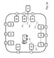
- FIGS. 2 a -2 g show exemplary states in an initialization according to the invention of a network related here at different points in time;
- FIG. 3 a shows a table of an exemplary time sequence of a communication protocol for measuring distance in a localization segment in accordance with the invention, as becomes valid after the initialization of a segment shown in FIG. 1 is complete.
- This table corresponds to a basic TDMA slot map, which forms a basic sequence of time slots;
- FIG. 3 b shows an exemplary channel distribution in a network formed from more than one segment, wherein each of the individual segments is constructed in a similar way to the segment shown in FIG. 1 ;
- FIG. 4 shows an exemplary embodiment of the method according to the invention for network initialization based on a flow diagram.
- FIG. 1 shows an exemplary logical structure of a locating segment, formed from two daisy chains, of a localization network.
- communication messages between “neighboring” participants are sequentially propagated within the two “daisy chains”.
- the arrangement shown in FIG. 1 includes an administration node 100 that, in the exemplary embodiment, has an inherently known data connection to an external IT server 110 via an ethernet connection 105 .
- This server functionality can also be implemented in the administration node 100 itself.
- a limited space is defined by the line 115 , the participants being arranged in said space or being able to move (dynamically).
- Power supply units 120 , 120 ′ are arranged on this outer limit line 115 in order to supply the participants with the electrical energy required for their operation.
- a first daisy chain (C 1 ) 125 In the lower half of the drawing, a first daisy chain (C 1 ) 125 , and in the upper half of the drawing a second daisy chain (C 2 ) 130 , branch off from the administration node 100 .
- a localization measurement of participants carried out in the network shown in FIG. 1 takes place using the known method of “trilateration”.
- This method is based on the fact that, in case of knowing only the distance of an object to a known point, its own location (in planar view) is on a sphere or, in a 3D space, on a spherical shell around this point. In the case of two known points, its own location is on the points of intersection of the two spherical shells, i.e. on a circular line.
- FIGS. 2 a -2 g exemplary method steps of a first exemplary embodiment of the method according to the invention for initializing a network segment exemplarily shown in FIG. 1 using a sequence of network statuses are illustrated.
- a single locating object 200 is shown in these drawings ( FIGS. 2 a -2 g ), which is not yet registered and, accordingly, is not yet a “participant” in the current sense.
- the object 200 is provided with a human ear 205 in order to signify that the object 200 , as described in detail in the following, listens to a broadcast channel.
- the two daisy chains can also contain different numbers of reference nodes. However, a symmetrical construction from the point of view of resource efficiency and maximum measuring speed in the subsequent measurement operation is preferable.
- the reference nodes from the daisy chain C 1 are labelled in the following with the numbers 11 ′ to 15 ′ contained in FIG. 1
- the reference nodes from the daisy chain C 2 are labelled with the numbers 21 ′ to 25 ′.
- all participants 200 , 215 - 235 and 240 - 260 are in a so-called “ALOHA” mode at the start of the initialization. Communication in ALOHA mode takes place based on a “listen before talk” procedure with additional stochastic telegram communication.
- the participants, with the exception of the administration node are in a standby position in which they initially only listen to the different broadcast channels and do not send any of their own messages. During this process, every administration node, i.e.
- the administration node 210 transmits initialization commands together with information on network topology and the configuration status of the administration node, which is primarily determined for the reference nodes in its own segment and is also especially necessary for later distance measurements.
- the information on the network topology includes the number and SIDS of the segments configured in the network, the UlDs of all reference nodes available in the localization network and its assignment to the respective segment.
- the reference nodes are assigned with a provisional LID in their own segment.
- the information on the configuration status of the administration node consists primarily of information on its firmware status.
- the reference nodes 215 - 260 switch between the different possible broadcasting channels until they receive initial information from a broadcast of a random segment as to whether and in which segment they are a reference node or not. If necessary, they switch to the broadcast channel of the segment in which they are specified as a reference in order to participate in the correct segment in the network initialization.
- the reference nodes take part in the communication 261 , 261 ′, 261 ′′ and 261 ′′′ in their segment by repeating the initialization command and information of the administration node during the simultaneous distance measurement to any reference nodes in their segment, as can be seen in FIG. 2 b .
- the reference nodes also create a neighbor database by evaluating the communication taking place, by means of which both daisy chains of the reference nodes can be subsequently autarkically operated.
- the neighbor database Along with the measured distance to the other reference nodes, in the neighbor database there is also information on the received signal amplitudes (V Peak ), the background noise and the occurrence or failure of UWB connections, by means of which the following most stable (in terms of communication) possible daisy chains can be formed.
- the above described communication expands in an avalanche-like way in the network.
- a sufficiently long waiting period is necessary to ensure that all reference nodes are able to participate in this chaotic communication flow for long enough in order to generate a reliable database in the statistics and neighbor database.
- the end of this first initialization phase is triggered by the administration node transmitting a new command instead of the initialization command which instructs the reference nodes to communicate the respectively logged statistics database to this segment.
- resulting distance measurements are not necessary.
- This command expands in an avalanche-like way within the segment. Reference nodes repeat this command randomly in turn together with the content of their neighbor database.
- Neighbor databases that have been listened to of other reference nodes are completely integrated into their own database and the updated data set is transmitted if the communication process is participated in once more. The result of this is that, after a certain period of time has elapsed, all reference nodes and the administration node have the same information, which is complete from the point of view of communication, about the neighboring relationships in the network segment. If the administration node does not detect any more change in the neighbor database for a certain amount of time, or if a certain maximum waiting time has expired, the administration node ends the described spreading of the neighbor(hood) database in the network.
- the administration node calculates a stable daisy chain structure from the information collected. Different weightings can thus be used for the statistical information recorded in the neighbor database, which, when added together, ensure that information can be reliably and completely propagated along the daisy chain. In order to achieve a higher tolerance to errors, it can e.g. be taken into account that next-but-one or next-but-two neighbors within the formed daisy chain are also able to communicate directly with each other as reliably as possible. Furthermore, the administration node can also assign the reference nodes with a new LID, which e.g. indicates their daisy chain and position within this. It is shown in FIG.
- the administration node 210 transmits 262 (as respectively implied by the circular wave propagation) the chain setup information together with a counter to diagnose the propagation of this message to the nearest reference node 215 .
- This reference node communicates this information 263 , in turn, to the next reference node 220 .
- the two reference nodes 225 , 230 following this also communicate 264 - 266 the chain setup information until the last reference node 235 of the lower daisy chain.
- Said chain setup information comprises amoung others the chain length and corresponding UIDS, and if available the new LIDS for reference nodes participating in the chain. If a reference node notices that the information it has sent is not being spread further, it resends the data package that it has already sent. This is advantageous because, in this way, the lower daisy chain can also receive information about the planned second daisy chain.
- FIG. 2 d a response to confirm the successful DC set-up starting from the last reference node 235 in the lower chain, by means of the reference nodes, or a corresponding propagation to all other reference nodes of this daisy chain, in which a chain setup “acknowledge” (i.e. corresponding acceptance or confirmation of the resultant chain generation) takes place, including the feedback of diagnostic information, e.g. in the form of the respective LID.
- the response starts by transmitting 268 a corresponding communication 269 to the next reference node which, in turn, transmits a corresponding communication 271 to the next reference node 270 . If forming the daisy chain has not been possible because the broadcast shown in FIG.
- the administration node 210 repeats the procedure described in the previous two paragraphs to form the upper DC. This is signified by communication along the arrows 273 - 277 which represents the formation of the DC from the reference nodes 240 - 260 . Along this new second DC, a chain set up “acknowledge” is finally also transmitted back to the administration node, analogously to the procedure described above. Thus, in the whole segment, the formation of both chains has occurred and is complete.
- the reference nodes then receive a complete dataset for describing the network. This is shown in FIG. 2 e .
- the administration node transmits information by means of forward broadcast 278 along the lower daisy chain, as is signified by the arrows 279 , 281 and 282 .
- the reference nodes repeat the respective complete received information.
- the data set for describing the network typically contains a complete almanac with the known positions of all reference nodes in the entire localization network. Further information can also be communicated to the selected coordinates system (coordinates transformation, rotation) and to logical spaces. Due to the data quantity, the information must be spread out on several data pages.
- a confirmation of the successful information transfer occurs from the end of the daisy chain or from the last reached participant via a feedback data and diagnostic diagram.
- the reference nodes Directly after the diagnostic information has been sent, the reference nodes generate the TDMA slot map shown in FIG. 3 and wait for the start of the synchronous communication phase via the administration node.
- the same process of the above described information spreading occurs first, as is also shown in FIG. 2 f for the second (upper) DC.
- the broadcast 284 in turn starts at the administration node and the information is then, as signified with the arrows 285 and 287 , spread along the DC until the last reference node. From there, a return broadcast 286 occurs along the DC back to the administration node.
- the reference nodes also switch to synchronous communication mode, based on the TDMA slot map shown in FIG. 3 .
- the initializing phase of this network segment is ended with the cycle of network information described here.
- the administration node After the last broadcast package, which is still responding, has been received from the upper DC, the administration node also switches to synchronous communication mode and, after a short waiting period, starts the TDMA communication by spreading a broadcast, as is depicted in first slot shown in FIG. 3 a .
- This broadcast informs all participants of the successful segment initialization. From this time onwards, the locating object 288 can register in this network segment with a random reference node via the communication 289 shown as an example in FIG. 2 g.
- the exemplary embodiment described above of the initialization of a localization network related here formed from at least two segments is described in the following using a flow diagram shown in FIG. 4 and is realized by the initialization of the individual network segments taking place in parallel or sequentially. Only the initialization of an individual network segment is described in the following, however this is undertaken in a uniform way for all segments of which the localization network consists. At the same time, initially only the initialization of the components belonging to the communication infrastructure i.e. in this case of the administration nodes and the reference nodes, is explicitly described. The initialization for locating objects, however, takes place in an identical manner to that of the reference nodes, unless a different mode of action is specifically referred to.
- Network segments can cycle through such an initialization up to any point in time.
- FIG. 4 and the process described in the following text when combined form the same behavior as described above based on FIGS. 2 a -2 g .
- the communication paths between the communication participants were in the middle of the description.
- the sequential process will now be shown and linked with the communication flow between the communication partners by referring to the previously described Figures.
- the initial state or starting state is characterized in that the reference nodes are in a so-called “ALOHA” broadcast mode 400 , in which provision is made for a “listen-before-talk” procedure with a stochastic telegram communication in an inherently known manner, however by switching off their own transmission function.
- the reference nodes only switch 405 , 410 , 415 between broadcast channels that are possibly available in order to detect the channels on which communication in this example is taking place via UWB radio technology.
- the reference nodes distribute very short data packages on a selected broadcast channel in the UWB network, which announce their basic presence. This is especially of advantage as soon as they have found a communication on the selected broadcast channel 420 .
- the dashed line 425 indicates that both steps 405 , 410 and 415 and all the following steps in the area bordered by the dashed line 425 will be carried out by the reference nodes. The situation is comparable with the behavior of the participants shown in FIG. 2 a.
- the dashed line 430 shown in FIG. 4 shows that the steps contained within it are carried out by the administration node.
- the administration node is switched to an initial state 435 in the same way as the reference nodes. If the administration node, as mentioned in FIG. 1 , does not have a data connection to a data processing unit or a control processor that starts the communication 440 , it also starts communication in said “ALOHA” mode after a presettable waiting time ⁇ t 1 , and it does this by transmitting 445 initialization data packages to the reference nodes (e.g. shown by the arrow 450 ).
- the administration node If the administration node has not yet detected a reference node in its vicinity, since these are still mute at the start of the initialization, it contacts a target address of a “virtual” reference node. If the administration node has a connection to an IT system, corresponding initialization packages can also be provided, triggered by the request 440 of the IT system.
- the aforementioned initialization packages consist of a localization measurement request to a random participant (reference node), from a command that signalizes the segment initialization, and also contain further data that describe the network topology as well as the configuration status of the administration node.
- this data may also include information on the firmware used, the number of available segments in the network and their SIDs, said UlDs of the reference nodes in the segment and/or in the entire localization network as well as the assignment of these reference nodes to the respective segments.
- the composition of this information requires that the administration node has an overview of the topology of the localization network. It can receive this overview via communication with an IT system or by means of configuration information 455 saved in its own read-only memory.
- a provisional specified LID can be assigned to the reference nodes which belong to an available network segment, and communicated by means of the initialization package. If necessary, all of the aforementioned information can also be split into several different data packages, wherein the data packages are made identifiable through the addition of page numbers. During this process, not all pages of the initialization packages must be sent directly to every possible participant in the segment, since it is also sufficient if the participants are able to also hear the total number of different pages as part of said broadcast from the communication with the other participants.
- a reference node is arranged in terms of radio in a very shaded area, instead of the initialization package 450 of an administration node, the reception of the initialization packages which are, as described in the following, further spread, repeated and transmitted from another random reference node, can also result in the behavior described below.
- first reference nodes receive necessary information with regard to the segmentation of the network and which reference nodes are assigned to which segment, regardless of whether they have set the broadcast channel of their target segment or not. In particular, they actually only receive the information at this point that they are reference nodes and not locating objects. Locating objects determine their classification by the fact that their UID is not contained in the information of the initialization packages on the network structure. They remain passive until the entire configuration process of the selected network segment is completed. However, they listen to every single described communication flow as passive participants and process the communicated data.
- a test step 470 additionally carried out by a reference node when listening to the initialization packages, reveals that the broadcast channel of a network segment, which the reference node is not assigned to, having been set, the reference node switches 475 into the broadcast channel of the correct target segment to which it is assigned. If the reference nodes in the correct segment have received 480 information on their preliminary LID, they exit the passive ALOHA mode using this LID. This behavior is alternatively also shown in FIG. 2 b and the corresponding description text. On the one hand, the reference nodes make their presence 485 in the segment known via the broadcast channel.
- the reference nodes repeat the information about the structure of the network received to date from the administration node, in combination with a localization measurement of all other already detected reference nodes in the relevant segment or in the administration node. This secures the “avalanche effect” that now also almost all other reference nodes in the segment can contain the information of the administration node, if e.g., a radio shadow exists in environments with heavy interference. In addition to this it is ensured that reference nodes are not able to migrate into another segment.
- the reference nodes collect 490 statistics about the reference node from which in its own segment a communication 495 can be heard, at which signal and fault signal levels and how often a distance measurement to a respective reference node has worked or has failed. More data can be collected for error diagnosis, including also the number and or a list of successfully received initialization package pages. This repetition continues to take place until the administration node announces the end of the initialization phase by communication or transmitting a further command via UWB.
- the reference nodes can also be informed via an “a-priori” configuration that they represent reference nodes and/or to which network segment they are assigned. This means that a channel switch is not necessary.
- the initialization phase can be significantly reduced in this way, since only their provisional LID is communicated to the reference nodes, and a sufficient data base for the statistical information described above must be reached.
- the time period At 2 that the administration node waits until it begins the next communication phase must be sufficiently long.
- the length of this time period At 2 can have a fixed configuration, be controlled via a control processor or a data processing unit or the flow of this time can be communicated by an external signal or via UWB 500 .
- the initialization phase is ended 505 by the administration node in accordance with the conditions for the administration nodes described above, in this exemplary embodiment by the transmission of a command 510 .
- this command requests the reference nodes to stop spreading the initialization packages and instead to provide 515 the network with statistics about communication with other participants, wherein provision can be made for forgoing distance measurements for the benefit of pure data communication.
- the information collected from the reference nodes specified above relating to listened to participants, signal strengths etc. can in turn be packaged and transmitted 515 as data packages in the form of an XML string or in a text-based or binary exchange format.
- This exchange of statistics 515 takes place once the command that the administration node has sent, and that announces the end of the initialization phase, has been repeated. If a reference node cannot hear the administration node directly, at least in this way 520 it will be informed of the end of the initialization phase.
- the reference nodes process 525 the statistical data listened to via the broadcast signal regarding the neighboring situation, and thus supplement their entire database. In further communication packages, this updated and combined statistics database is then finally always made available to the entire segment. Ultimately, all reference nodes including the administration node have consistent information regarding the communication properties in the network.
- the administration node 540 or an IT system connected to it forms a stable segment structure in the form of functioning daisy chains.
- This behavior is also shown in FIG. 2 c and the corresponding description.
- two chains are formed from reference nodes which guarantee as reliable a data exchange as possible. Both chains are preferably of the same length.
- the chains can also be formed by a ring structure, a star structure or a branched structure of another kind, provided that a linear connection between two reference points is formed at least locally.
- the reference nodes can also automatically end their spreading optionally after a period of time in which they no longer detect a change to the statistics database.
- the radio communication between the reference nodes can, however, also be ended by spreading the information to the daisy chain via the administration node 545 or the other reference nodes 550 , in accordance with the model described below.
- the transmitter does not receive a confirmation of receipt of the chain information, it resends the package.
- the last reference node in the C 1 chain If the last reference node in the C 1 chain has finally received the information about the chain and taken on the correct LID, it starts to send a response data package that confirms the acceptance and correct formation of the daisy chain.
- the confirmation is transmitted along the daisy chain backwards 570 to the administration node 575 .
- the data package contains the entire chain of LIDs of the participants via which the data package is further spread. Sender and addressee are also clearly marked in this response package.
- the reference node which has lastly successfully received its daisy chain information along the daisy chain but has not received a confirmation from the forwarding process, alternatively starts to send the response acceptance package.
- the administration node can then decide 580 whether a chain has been formed “sufficiently” correctly, whether another chain configuration must potentially be chosen, or whether the localization segment is in an error state. If it was possible to correctly form the chain, or if the administration node decides to continue the segment configuration process despite erroneous chain formation, it continues 585 to apply 590 the same method that was used to form the chain C 1 to the second chain, chain C 2 . This is also shown in FIG. 2 d .
- the administration node also again receives a response 595 regarding the acceptance of the daisy chain from the formation of this chain. On the basis of this response, the administration node must, in turn, also decide 600 whether, overall, a stable communication structure was able to arise or be formed in the network segment.
- the calculation of the daisy chains can also take place in parallel on all reference nodes.
- a similar daisy chain structure in the case of a parallel, isolated calculation can be achieved.
- the administration node 605 starts to communicate or distribute 610 further information that it has about the topology of the entire network firstly along the chain C 1 .
- This information consists of information on the transformation of the selected coordinates system into other coordinates systems, an almanac list (called “almanac”), as well as further information that relates to the location in the localization network or a network diagnosis.
- a specified almanac list includes the existing reference nodes in the entire network and their respective position in the space.
- the list includes information about each participant which is a unique identifier (“UID”) of the participant in the network unrelated to the respective position in the network, e.g. an inherently known “MAC-ID”.
- UID unique identifier
- the administration node After the receipt and forwarding of the confirmation package by the respective reference node, it 625 generates a TDMA slot map, shown in a table in FIG. 3 as an example, for a localization segment, initially without active participants.
- the reference node switches to the TDMA mode during this process.
- the administration node After receiving the configuration confirmation from C 2 in accordance with the previous paragraph, the administration node waits for a determined amount of time before it announces the successful communication and complete initialization to the network or segment by a separate command.
- the length of this period of time can be pre-configured, predetermined via a control processor or a data processing unit, or the flow of the time period can be communicated 630 by an external signal or via UWB.
- the administration node in its first regular forward broadcast package in the first slot of the TDMA slot map, communicates the successful segment configuration to the localization segment.
- This message is propagated along the daisy chain. It receives the confirmation of this from the daisy chains of the segment via a return broadcast package.
- the broadcast package that communicates the successful segment configuration is repeated by the administration node with each first slot of the TDMA slot map until a confirmation has been received by all reference nodes. Normally, this is the case after the first cycle of the TDMA slot map.
- the network segment has then reached its configuration status and is ready for the localization of participants.
- the slot map used here thus only represents one possible variation and other implementations are conceivable.
- locating objects behave in a passive way during the entire segment or network initialization process. If this process is complete, they begin to integrate themselves into the localization segment. It should be pointed out at this point that, if the locating object has also listened to the entire initialization communication of a network segment, the registration process drastically shortens, since all current information about the status of a network is already available, and is communicated and processed simultaneously with the transfer of the localization segment in the measurement process. The log-on process then takes place almost immediately and only while communicating a minimum amount of data.
- the selected allocated sequence of SIDS in the examples shown is selected in a regular pattern which represents a suitable implementation in an isotropic space.
- a random pattern adapted to the respective usage scenario can be selected to allocate the SID in order to further improve protection from cross-talking.
- the implementation shown therefore only constitutes one possible embodiment of the method described.
Landscapes
- Engineering & Computer Science (AREA)
- Computer Networks & Wireless Communication (AREA)
- Radar, Positioning & Navigation (AREA)
- Remote Sensing (AREA)
- Signal Processing (AREA)
- Physics & Mathematics (AREA)
- General Physics & Mathematics (AREA)
- Databases & Information Systems (AREA)
- Mobile Radio Communication Systems (AREA)
- Small-Scale Networks (AREA)
Applications Claiming Priority (3)
| Application Number | Priority Date | Filing Date | Title |
|---|---|---|---|
| DE102016107940.5A DE102016107940A1 (de) | 2016-04-28 | 2016-04-28 | Verfahren zur Netzwerkinitialisierung eines Netzwerks zur Funkortung von Objekten innerhalb eines begrenzten Raumes |
| DE102016107940 | 2016-04-28 | ||
| DE102016107940.5 | 2016-04-28 |
Publications (2)
| Publication Number | Publication Date |
|---|---|
| US20170315223A1 US20170315223A1 (en) | 2017-11-02 |
| US10126419B2 true US10126419B2 (en) | 2018-11-13 |
Family
ID=58314093
Family Applications (1)
| Application Number | Title | Priority Date | Filing Date |
|---|---|---|---|
| US15/490,998 Expired - Fee Related US10126419B2 (en) | 2016-04-28 | 2017-04-19 | Method for the network initialization of a network for the radio location of objects within a limited space |
Country Status (4)
| Country | Link |
|---|---|
| US (1) | US10126419B2 (de) |
| EP (1) | EP3258286B1 (de) |
| CN (1) | CN107426002A (de) |
| DE (1) | DE102016107940A1 (de) |
Cited By (1)
| Publication number | Priority date | Publication date | Assignee | Title |
|---|---|---|---|---|
| US10638446B2 (en) | 2018-03-05 | 2020-04-28 | Jungheinrich Ag | Location system and method for operating a location system for detecting the position of at least one mobile unit in a goods logistics facility |
Families Citing this family (5)
| Publication number | Priority date | Publication date | Assignee | Title |
|---|---|---|---|---|
| US10877162B2 (en) * | 2017-05-12 | 2020-12-29 | Skypersonic Inc. | Terrestrial based positioning systems and methods |
| US10624707B2 (en) | 2017-09-18 | 2020-04-21 | Verb Surgical Inc. | Robotic surgical system and method for communicating synchronous and asynchronous information to and from nodes of a robotic arm |
| US10779901B2 (en) * | 2017-09-18 | 2020-09-22 | Verb Surgical Inc. | Robotic surgical system having a communication network of a ring topology and method for use therewith |
| CN108364100B (zh) * | 2018-02-12 | 2022-02-11 | 杭州蓝芯科技有限公司 | 一种基于动态节点检测的多agv调度方法 |
| US12604340B2 (en) * | 2023-10-13 | 2026-04-14 | GM Global Technology Operations LLC | Systems and methods for optimizing channels using WI-FI 7 |
Citations (5)
| Publication number | Priority date | Publication date | Assignee | Title |
|---|---|---|---|---|
| US6133876A (en) | 1998-03-23 | 2000-10-17 | Time Domain Corporation | System and method for position determination by impulse radio |
| US7092914B1 (en) * | 1997-11-06 | 2006-08-15 | Intertrust Technologies Corporation | Methods for matching, selecting, narrowcasting, and/or classifying based on rights management and/or other information |
| US7873099B2 (en) | 1999-06-14 | 2011-01-18 | Time Domain Corporation | Time transfer using ultra wideband signals |
| US20170055121A1 (en) * | 2015-08-19 | 2017-02-23 | Brendan Ciecko | Prioritized activity based location aware content delivery system |
| US20170201865A1 (en) * | 2016-01-12 | 2017-07-13 | Electronics And Telecommunications Research Institute | Location estimation apparatus and method using combination of different positioning resources |
Family Cites Families (5)
| Publication number | Priority date | Publication date | Assignee | Title |
|---|---|---|---|---|
| CN101873691A (zh) * | 2010-06-09 | 2010-10-27 | 中国人民解放军海军航空工程学院 | 基于连通性的无需测距的无线传感器网络节点定位方法 |
| CN102638863B (zh) * | 2012-03-20 | 2014-10-29 | 东南大学 | 一种无线传感器网络中的移动目标跟踪方法 |
| US9438440B2 (en) * | 2013-07-29 | 2016-09-06 | Qualcomm Incorporated | Proximity detection of internet of things (IoT) devices using sound chirps |
| US9491575B2 (en) * | 2014-06-13 | 2016-11-08 | Qualcomm Incorporated | Positioning beacons with wireless backhaul |
| CN203933958U (zh) * | 2014-06-18 | 2014-11-05 | 东华大学 | 一种无线数字家庭定位系统 |
-
2016
- 2016-04-28 DE DE102016107940.5A patent/DE102016107940A1/de not_active Withdrawn
-
2017
- 2017-03-07 EP EP17159676.0A patent/EP3258286B1/de active Active
- 2017-04-19 US US15/490,998 patent/US10126419B2/en not_active Expired - Fee Related
- 2017-04-27 CN CN201710285970.4A patent/CN107426002A/zh active Pending
Patent Citations (5)
| Publication number | Priority date | Publication date | Assignee | Title |
|---|---|---|---|---|
| US7092914B1 (en) * | 1997-11-06 | 2006-08-15 | Intertrust Technologies Corporation | Methods for matching, selecting, narrowcasting, and/or classifying based on rights management and/or other information |
| US6133876A (en) | 1998-03-23 | 2000-10-17 | Time Domain Corporation | System and method for position determination by impulse radio |
| US7873099B2 (en) | 1999-06-14 | 2011-01-18 | Time Domain Corporation | Time transfer using ultra wideband signals |
| US20170055121A1 (en) * | 2015-08-19 | 2017-02-23 | Brendan Ciecko | Prioritized activity based location aware content delivery system |
| US20170201865A1 (en) * | 2016-01-12 | 2017-07-13 | Electronics And Telecommunications Research Institute | Location estimation apparatus and method using combination of different positioning resources |
Non-Patent Citations (2)
| Title |
|---|
| DE 10 2016 103 077.5 filed Feb. 22, 2016. |
| U.S. Appl. No. 15/403,264, filed Jan. 11, 2017. |
Cited By (1)
| Publication number | Priority date | Publication date | Assignee | Title |
|---|---|---|---|---|
| US10638446B2 (en) | 2018-03-05 | 2020-04-28 | Jungheinrich Ag | Location system and method for operating a location system for detecting the position of at least one mobile unit in a goods logistics facility |
Also Published As
| Publication number | Publication date |
|---|---|
| EP3258286A1 (de) | 2017-12-20 |
| US20170315223A1 (en) | 2017-11-02 |
| CN107426002A (zh) | 2017-12-01 |
| EP3258286B1 (de) | 2019-07-24 |
| DE102016107940A1 (de) | 2017-11-02 |
Similar Documents
| Publication | Publication Date | Title |
|---|---|---|
| US20170315223A1 (en) | Method for the network initialization of a network for the radio location of objects within a limited space | |
| US11812334B2 (en) | Dynamic anchor assignments for UWB ranging | |
| CN101730226B (zh) | 用于支持无线节点的移动性的定位消息处理的方法 | |
| US10924157B2 (en) | Methods, systems, and computer readable media for distribution of time synchronization information to ultra-wide-band devices | |
| US8548490B2 (en) | Multi-objects positioning system and power-control based multiple access control method | |
| US6934298B2 (en) | Hot standby access point | |
| US10534938B2 (en) | Array of very light readers for active RFID and location applications | |
| EP4094088B1 (de) | Flugzeitbasiertes vereinheitlichtes positionierungssystem und -verfahren | |
| US6580909B1 (en) | Communications system and method based on the relative positions of mobile units | |
| Ganesan | 5G advanced: Sidelink evolution | |
| CN107105402B (zh) | 对有限空间内的对象进行无线电定位的网络布置和方法 | |
| KR20220023677A (ko) | 전자 디바이스 및 전자 디바이스의 위치 정보 획득 방법 | |
| Heyi | Implementation of Indoor Positioning using IEEE802. 15.4 a (UWB) | |
| Gui et al. | A range-free localization protocol for wireless sensor networks | |
| Kim et al. | IEEE 802.15. 4 MAC-based location-ID exchange protocol for realizing micro-cell connectionless location-awareness services | |
| Yogeshwary | Iterative Localization Technique for Underwater Wireless Sensor Networks | |
| CN115315015B (zh) | 一种用于光伏电站的通信方法 | |
| Choi et al. | Efficient Congestion Control Utilizing Message Eavesdropping in Asynchronous Range‐Based Localization | |
| WO2025058839A1 (en) | System and methods for untracked navigation using ultra-wideband devices | |
| Kheiri et al. | Impulse Ultrawideband ad-hoc tracking and communication network | |
| JP2024049038A (ja) | 無線局、通信方法、無線端末及び無線通信システム | |
| Liu et al. | A collision free neighbor discovery protocol for wireless positioning applications |
Legal Events
| Date | Code | Title | Description |
|---|---|---|---|
| AS | Assignment |
Owner name: BALLUFF GMBH, GERMANY Free format text: ASSIGNMENT OF ASSIGNORS INTEREST;ASSIGNORS:HELDMAIER, MATTHIAS MICHAEL;SCHUERZINGER, ANDREAS;SCHWEIZER, DANIEL;SIGNING DATES FROM 20170317 TO 20170403;REEL/FRAME:042094/0596 |
|
| STCF | Information on status: patent grant |
Free format text: PATENTED CASE |
|
| FEPP | Fee payment procedure |
Free format text: MAINTENANCE FEE REMINDER MAILED (ORIGINAL EVENT CODE: REM.); ENTITY STATUS OF PATENT OWNER: LARGE ENTITY |
|
| LAPS | Lapse for failure to pay maintenance fees |
Free format text: PATENT EXPIRED FOR FAILURE TO PAY MAINTENANCE FEES (ORIGINAL EVENT CODE: EXP.); ENTITY STATUS OF PATENT OWNER: LARGE ENTITY |
|
| STCH | Information on status: patent discontinuation |
Free format text: PATENT EXPIRED DUE TO NONPAYMENT OF MAINTENANCE FEES UNDER 37 CFR 1.362 |
|
| FP | Lapsed due to failure to pay maintenance fee |
Effective date: 20221113 |