US10123845B2 - Robotic devices and systems for performing single incision procedures and natural orifice translumenal endoscopic surgical procedures, and methods of configuring robotic devices and systems - Google Patents
Robotic devices and systems for performing single incision procedures and natural orifice translumenal endoscopic surgical procedures, and methods of configuring robotic devices and systems Download PDFInfo
- Publication number
- US10123845B2 US10123845B2 US15/814,140 US201715814140A US10123845B2 US 10123845 B2 US10123845 B2 US 10123845B2 US 201715814140 A US201715814140 A US 201715814140A US 10123845 B2 US10123845 B2 US 10123845B2
- Authority
- US
- United States
- Prior art keywords
- assembly
- instrument
- arm assembly
- arm
- shoulder
- Prior art date
- Legal status (The legal status is an assumption and is not a legal conclusion. Google has not performed a legal analysis and makes no representation as to the accuracy of the status listed.)
- Active
Links
Images


Classifications
-
- A—HUMAN NECESSITIES
- A61—MEDICAL OR VETERINARY SCIENCE; HYGIENE
- A61B—DIAGNOSIS; SURGERY; IDENTIFICATION
- A61B34/00—Computer-aided surgery; Manipulators or robots specially adapted for use in surgery
- A61B34/30—Surgical robots
- A61B34/35—Surgical robots for telesurgery
-
- A—HUMAN NECESSITIES
- A61—MEDICAL OR VETERINARY SCIENCE; HYGIENE
- A61B—DIAGNOSIS; SURGERY; IDENTIFICATION
- A61B17/00—Surgical instruments, devices or methods, e.g. tourniquets
- A61B17/00234—Surgical instruments, devices or methods, e.g. tourniquets for minimally invasive surgery
-
- A—HUMAN NECESSITIES
- A61—MEDICAL OR VETERINARY SCIENCE; HYGIENE
- A61B—DIAGNOSIS; SURGERY; IDENTIFICATION
- A61B17/00—Surgical instruments, devices or methods, e.g. tourniquets
- A61B17/34—Trocars; Puncturing needles
- A61B17/3417—Details of tips or shafts, e.g. grooves, expandable, bendable; Multiple coaxial sliding cannulas, e.g. for dilating
- A61B17/3421—Cannulas
-
- A—HUMAN NECESSITIES
- A61—MEDICAL OR VETERINARY SCIENCE; HYGIENE
- A61B—DIAGNOSIS; SURGERY; IDENTIFICATION
- A61B34/00—Computer-aided surgery; Manipulators or robots specially adapted for use in surgery
- A61B34/25—User interfaces for surgical systems
-
- A—HUMAN NECESSITIES
- A61—MEDICAL OR VETERINARY SCIENCE; HYGIENE
- A61B—DIAGNOSIS; SURGERY; IDENTIFICATION
- A61B34/00—Computer-aided surgery; Manipulators or robots specially adapted for use in surgery
- A61B34/30—Surgical robots
-
- A—HUMAN NECESSITIES
- A61—MEDICAL OR VETERINARY SCIENCE; HYGIENE
- A61B—DIAGNOSIS; SURGERY; IDENTIFICATION
- A61B34/00—Computer-aided surgery; Manipulators or robots specially adapted for use in surgery
- A61B34/30—Surgical robots
- A61B34/37—Master-slave robots
-
- A—HUMAN NECESSITIES
- A61—MEDICAL OR VETERINARY SCIENCE; HYGIENE
- A61B—DIAGNOSIS; SURGERY; IDENTIFICATION
- A61B34/00—Computer-aided surgery; Manipulators or robots specially adapted for use in surgery
- A61B34/70—Manipulators specially adapted for use in surgery
- A61B34/76—Manipulators having means for providing feel, e.g. force or tactile feedback
-
- A—HUMAN NECESSITIES
- A61—MEDICAL OR VETERINARY SCIENCE; HYGIENE
- A61B—DIAGNOSIS; SURGERY; IDENTIFICATION
- A61B90/00—Instruments, implements or accessories specially adapted for surgery or diagnosis and not covered by any of the groups A61B1/00 - A61B50/00, e.g. for luxation treatment or for protecting wound edges
- A61B90/36—Image-producing devices or illumination devices not otherwise provided for
- A61B90/361—Image-producing devices, e.g. surgical cameras
-
- A—HUMAN NECESSITIES
- A61—MEDICAL OR VETERINARY SCIENCE; HYGIENE
- A61B—DIAGNOSIS; SURGERY; IDENTIFICATION
- A61B1/00—Instruments for performing medical examinations of the interior of cavities or tubes of the body by visual or photographical inspection, e.g. endoscopes; Illuminating arrangements therefor
- A61B1/00147—Holding or positioning arrangements
-
- A—HUMAN NECESSITIES
- A61—MEDICAL OR VETERINARY SCIENCE; HYGIENE
- A61B—DIAGNOSIS; SURGERY; IDENTIFICATION
- A61B1/00—Instruments for performing medical examinations of the interior of cavities or tubes of the body by visual or photographical inspection, e.g. endoscopes; Illuminating arrangements therefor
- A61B1/04—Instruments for performing medical examinations of the interior of cavities or tubes of the body by visual or photographical inspection, e.g. endoscopes; Illuminating arrangements therefor combined with photographic or television appliances
- A61B1/05—Instruments for performing medical examinations of the interior of cavities or tubes of the body by visual or photographical inspection, e.g. endoscopes; Illuminating arrangements therefor combined with photographic or television appliances characterised by the image sensor, e.g. camera, being in the distal end portion
-
- A—HUMAN NECESSITIES
- A61—MEDICAL OR VETERINARY SCIENCE; HYGIENE
- A61B—DIAGNOSIS; SURGERY; IDENTIFICATION
- A61B1/00—Instruments for performing medical examinations of the interior of cavities or tubes of the body by visual or photographical inspection, e.g. endoscopes; Illuminating arrangements therefor
- A61B1/313—Instruments for performing medical examinations of the interior of cavities or tubes of the body by visual or photographical inspection, e.g. endoscopes; Illuminating arrangements therefor for introducing through surgical openings, e.g. laparoscopes
- A61B1/3132—Instruments for performing medical examinations of the interior of cavities or tubes of the body by visual or photographical inspection, e.g. endoscopes; Illuminating arrangements therefor for introducing through surgical openings, e.g. laparoscopes for laparoscopy
-
- A—HUMAN NECESSITIES
- A61—MEDICAL OR VETERINARY SCIENCE; HYGIENE
- A61B—DIAGNOSIS; SURGERY; IDENTIFICATION
- A61B18/00—Surgical instruments, devices or methods for transferring non-mechanical forms of energy to or from the body
- A61B18/04—Surgical instruments, devices or methods for transferring non-mechanical forms of energy to or from the body by heating
- A61B18/12—Surgical instruments, devices or methods for transferring non-mechanical forms of energy to or from the body by heating by passing a current through the tissue to be heated, e.g. high-frequency current
- A61B18/14—Probes or electrodes therefor
- A61B18/1442—Probes having pivoting end effectors, e.g. forceps
- A61B18/1445—Probes having pivoting end effectors, e.g. forceps at the distal end of a shaft, e.g. forceps or scissors at the end of a rigid rod
-
- A—HUMAN NECESSITIES
- A61—MEDICAL OR VETERINARY SCIENCE; HYGIENE
- A61B—DIAGNOSIS; SURGERY; IDENTIFICATION
- A61B17/00—Surgical instruments, devices or methods, e.g. tourniquets
- A61B17/00234—Surgical instruments, devices or methods, e.g. tourniquets for minimally invasive surgery
- A61B2017/00238—Type of minimally invasive operation
- A61B2017/00283—Type of minimally invasive operation with a device releasably connected to an inner wall of the abdomen during surgery, e.g. an illumination source
-
- A—HUMAN NECESSITIES
- A61—MEDICAL OR VETERINARY SCIENCE; HYGIENE
- A61B—DIAGNOSIS; SURGERY; IDENTIFICATION
- A61B17/00—Surgical instruments, devices or methods, e.g. tourniquets
- A61B17/28—Surgical forceps
- A61B17/29—Forceps for use in minimally invasive surgery
- A61B2017/2901—Details of shaft
- A61B2017/2906—Multiple forceps
-
- A—HUMAN NECESSITIES
- A61—MEDICAL OR VETERINARY SCIENCE; HYGIENE
- A61B—DIAGNOSIS; SURGERY; IDENTIFICATION
- A61B17/00—Surgical instruments, devices or methods, e.g. tourniquets
- A61B17/34—Trocars; Puncturing needles
- A61B17/3417—Details of tips or shafts, e.g. grooves, expandable, bendable; Multiple coaxial sliding cannulas, e.g. for dilating
- A61B17/3421—Cannulas
- A61B2017/3445—Cannulas used as instrument channel for multiple instruments
-
- A—HUMAN NECESSITIES
- A61—MEDICAL OR VETERINARY SCIENCE; HYGIENE
- A61B—DIAGNOSIS; SURGERY; IDENTIFICATION
- A61B17/00—Surgical instruments, devices or methods, e.g. tourniquets
- A61B17/34—Trocars; Puncturing needles
- A61B17/3417—Details of tips or shafts, e.g. grooves, expandable, bendable; Multiple coaxial sliding cannulas, e.g. for dilating
- A61B17/3421—Cannulas
- A61B2017/345—Cannulas for introduction into a natural body opening
-
- A—HUMAN NECESSITIES
- A61—MEDICAL OR VETERINARY SCIENCE; HYGIENE
- A61B—DIAGNOSIS; SURGERY; IDENTIFICATION
- A61B17/00—Surgical instruments, devices or methods, e.g. tourniquets
- A61B17/34—Trocars; Puncturing needles
- A61B17/3417—Details of tips or shafts, e.g. grooves, expandable, bendable; Multiple coaxial sliding cannulas, e.g. for dilating
- A61B2017/3454—Details of tips
- A61B2017/346—Details of tips with wings
-
- A—HUMAN NECESSITIES
- A61—MEDICAL OR VETERINARY SCIENCE; HYGIENE
- A61B—DIAGNOSIS; SURGERY; IDENTIFICATION
- A61B18/00—Surgical instruments, devices or methods for transferring non-mechanical forms of energy to or from the body
- A61B2018/00571—Surgical instruments, devices or methods for transferring non-mechanical forms of energy to or from the body for achieving a particular surgical effect
- A61B2018/00589—Coagulation
-
- A—HUMAN NECESSITIES
- A61—MEDICAL OR VETERINARY SCIENCE; HYGIENE
- A61B—DIAGNOSIS; SURGERY; IDENTIFICATION
- A61B18/00—Surgical instruments, devices or methods for transferring non-mechanical forms of energy to or from the body
- A61B2018/00571—Surgical instruments, devices or methods for transferring non-mechanical forms of energy to or from the body for achieving a particular surgical effect
- A61B2018/00601—Cutting
-
- A—HUMAN NECESSITIES
- A61—MEDICAL OR VETERINARY SCIENCE; HYGIENE
- A61B—DIAGNOSIS; SURGERY; IDENTIFICATION
- A61B18/00—Surgical instruments, devices or methods for transferring non-mechanical forms of energy to or from the body
- A61B2018/00982—Surgical instruments, devices or methods for transferring non-mechanical forms of energy to or from the body combined with or comprising means for visual or photographic inspections inside the body, e.g. endoscopes
-
- A—HUMAN NECESSITIES
- A61—MEDICAL OR VETERINARY SCIENCE; HYGIENE
- A61B—DIAGNOSIS; SURGERY; IDENTIFICATION
- A61B18/00—Surgical instruments, devices or methods for transferring non-mechanical forms of energy to or from the body
- A61B18/04—Surgical instruments, devices or methods for transferring non-mechanical forms of energy to or from the body by heating
- A61B18/12—Surgical instruments, devices or methods for transferring non-mechanical forms of energy to or from the body by heating by passing a current through the tissue to be heated, e.g. high-frequency current
- A61B18/14—Probes or electrodes therefor
- A61B18/1442—Probes having pivoting end effectors, e.g. forceps
- A61B2018/146—Scissors
-
- A—HUMAN NECESSITIES
- A61—MEDICAL OR VETERINARY SCIENCE; HYGIENE
- A61B—DIAGNOSIS; SURGERY; IDENTIFICATION
- A61B34/00—Computer-aided surgery; Manipulators or robots specially adapted for use in surgery
- A61B34/30—Surgical robots
- A61B2034/302—Surgical robots specifically adapted for manipulations within body cavities, e.g. within abdominal or thoracic cavities
-
- A—HUMAN NECESSITIES
- A61—MEDICAL OR VETERINARY SCIENCE; HYGIENE
- A61B—DIAGNOSIS; SURGERY; IDENTIFICATION
- A61B34/00—Computer-aided surgery; Manipulators or robots specially adapted for use in surgery
- A61B34/30—Surgical robots
- A61B2034/305—Details of wrist mechanisms at distal ends of robotic arms
-
- A—HUMAN NECESSITIES
- A61—MEDICAL OR VETERINARY SCIENCE; HYGIENE
- A61B—DIAGNOSIS; SURGERY; IDENTIFICATION
- A61B90/00—Instruments, implements or accessories specially adapted for surgery or diagnosis and not covered by any of the groups A61B1/00 - A61B50/00, e.g. for luxation treatment or for protecting wound edges
- A61B90/30—Devices for illuminating a surgical field, the devices having an interrelation with other surgical devices or with a surgical procedure
- A61B2090/309—Devices for illuminating a surgical field, the devices having an interrelation with other surgical devices or with a surgical procedure using white LEDs
-
- A—HUMAN NECESSITIES
- A61—MEDICAL OR VETERINARY SCIENCE; HYGIENE
- A61B—DIAGNOSIS; SURGERY; IDENTIFICATION
- A61B90/00—Instruments, implements or accessories specially adapted for surgery or diagnosis and not covered by any of the groups A61B1/00 - A61B50/00, e.g. for luxation treatment or for protecting wound edges
- A61B90/36—Image-producing devices or illumination devices not otherwise provided for
- A61B90/361—Image-producing devices, e.g. surgical cameras
- A61B2090/3612—Image-producing devices, e.g. surgical cameras with images taken automatically
-
- A—HUMAN NECESSITIES
- A61—MEDICAL OR VETERINARY SCIENCE; HYGIENE
- A61B—DIAGNOSIS; SURGERY; IDENTIFICATION
- A61B90/00—Instruments, implements or accessories specially adapted for surgery or diagnosis and not covered by any of the groups A61B1/00 - A61B50/00, e.g. for luxation treatment or for protecting wound edges
- A61B90/36—Image-producing devices or illumination devices not otherwise provided for
- A61B90/37—Surgical systems with images on a monitor during operation
- A61B2090/371—Surgical systems with images on a monitor during operation with simultaneous use of two cameras
-
- Y—GENERAL TAGGING OF NEW TECHNOLOGICAL DEVELOPMENTS; GENERAL TAGGING OF CROSS-SECTIONAL TECHNOLOGIES SPANNING OVER SEVERAL SECTIONS OF THE IPC; TECHNICAL SUBJECTS COVERED BY FORMER USPC CROSS-REFERENCE ART COLLECTIONS [XRACs] AND DIGESTS
- Y10—TECHNICAL SUBJECTS COVERED BY FORMER USPC
- Y10S—TECHNICAL SUBJECTS COVERED BY FORMER USPC CROSS-REFERENCE ART COLLECTIONS [XRACs] AND DIGESTS
- Y10S901/00—Robots
- Y10S901/02—Arm motion controller
-
- Y—GENERAL TAGGING OF NEW TECHNOLOGICAL DEVELOPMENTS; GENERAL TAGGING OF CROSS-SECTIONAL TECHNOLOGIES SPANNING OVER SEVERAL SECTIONS OF THE IPC; TECHNICAL SUBJECTS COVERED BY FORMER USPC CROSS-REFERENCE ART COLLECTIONS [XRACs] AND DIGESTS
- Y10—TECHNICAL SUBJECTS COVERED BY FORMER USPC
- Y10S—TECHNICAL SUBJECTS COVERED BY FORMER USPC CROSS-REFERENCE ART COLLECTIONS [XRACs] AND DIGESTS
- Y10S901/00—Robots
- Y10S901/27—Arm part
Definitions
- the present disclosure relates generally to systems, devices, and methods, and more specifically, relates to systems, devices, and methods for use in performing procedures via a single incision or a natural orifice.
- MIS minimally invasive surgery
- a typical MIS procedure requires multiple incisions to a patient in order to allow access via the incisions for the insertion of a camera and various other laparoscopic instruments into the body cavity of the patient.
- surgical robotic devices oftentimes encounter difficulties during surgical procedures due to insufficient anchoring and/or reactive forces to stabilize against forces that are desired and/or necessary to be applied during surgical actions.
- surgical robotic systems face difficulties in providing an instrument, such as a cutting or gripping instrument attached to the end of a surgical robotic arm, with access to all or even most parts, areas, and/or quadrants of abdominal cavity of a patient. That is, after the surgical robotic arm is inserted in the abdominal cavity of the patient and ready to perform a surgical action, the instrument attached to the end of the surgical robotic arm is typically limited to access only certain parts, areas, and quadrants of the abdominal cavity of the patient.
- known surgical robotic systems typically provide only between one to two surgical robotic arms per access or opening (such as an incision or a natural orifice) of the patient.
- one or more additional incisions will be required for the insertion of a camera and various laparoscopic instruments into the abdominal cavity of the patient.
- Present example embodiments relate generally to systems, devices, and methods for addressing one or more problems in surgical robotic systems, devices, and methods, including those described above and herein.
- a surgical system is described in the present disclosure.
- the surgical system may be for use in performing natural orifice transluminal endoscopic surgery (NOTES).
- NOTES natural orifice transluminal endoscopic surgery
- the surgical system may comprise an end-effector assembly, a first arm assembly, and a second arm assembly.
- The may include a first instrument assembly and a wrist assembly.
- the first instrument assembly may include a first instrument for performing a surgical action.
- the first instrument assembly may further include a first instrument driven portion configurable to be driven in such a way as to move the first instrument relative to a first axis.
- the wrist assembly may be securable to the first instrument assembly.
- the wrist assembly may include a wrist driven portion configurable to be driven in such a way as to move the first instrument relative to a second axis, the second axis being different from the first axis.
- the first arm assembly may be securable to the end-effector assembly.
- the first arm assembly may include a first arm assembly body, a first arm assembly joint portion, a wrist connector portion, a first instrument drive assembly, a wrist drive assembly, and a first arm assembly drive assembly.
- the first arm assembly body may include a first end and a second end opposite to the first end.
- the first arm assembly joint portion may be for use in joining the first arm assembly to a second arm assembly.
- the first arm assembly joint portion may be secured to the first end of the first arm assembly body.
- the wrist connector portion may be configurable to secure to the wrist assembly.
- the first instrument drive assembly may be securely housed in the first arm assembly body.
- the first instrument drive assembly may include at least a first integrated motor and a first instrument drive portion.
- the first instrument drive portion may be controllable by the first integrated motor to drive the first instrument driven portion when the wrist connector portion is secured to the wrist assembly.
- the wrist drive assembly may be securely housed in the first arm assembly body.
- the wrist drive assembly may include at least a second integrated motor and a wrist drive portion.
- the wrist drive portion may be controllable by the second integrated motor to drive the wrist driven portion when the wrist connector portion is secured to the wrist assembly.
- the first arm assembly drive assembly may be securely housed in the first arm assembly body.
- the first arm assembly drive assembly may include at least a third integrated motor and a first arm assembly drive portion.
- the first arm assembly drive portion may be controllable by the third integrated motor to drive the first arm assembly body to move relative to the second arm assembly.
- a surgical system is described in the present disclosure.
- the surgical system may be for use in performing natural orifice transluminal endoscopic surgery (NOTES).
- NOTES natural orifice transluminal endoscopic surgery
- the surgical system may comprise an end-effector assembly and an arm assembly.
- the end-effector assembly may include a first instrument assembly.
- the first instrument assembly may include a first instrument for performing a surgical action.
- the first instrument assembly may also include a first instrument driven portion configurable to be driven in such a way as to move the first instrument relative to a first axis.
- the arm assembly may include a first arm assembly body, a second arm assembly body, a first arm assembly joint portion, an end-effector connector portion, a first instrument drive assembly, and a first arm assembly drive assembly.
- the first arm assembly body may include a first end and a second end opposite to the first end.
- the second arm assembly body may include a first end and a second end opposite to the first end.
- the first arm assembly joint portion may be for use in joining the first arm assembly body to the second arm assembly body.
- the first arm assembly joint portion may be secured to the first end of the first arm assembly body.
- the end-effector connector portion may be provided at the second end of the first arm assembly body.
- the end-effector connector portion may be configurable to secure to at least a portion of the end-effector assembly.
- the first instrument drive assembly may include at least a first integrated motor and a first instrument drive portion.
- the first instrument drive portion may be controllable by the first integrated motor to drive the first instrument driven portion when the end-effector connector portion is secured to the end-effector assembly.
- the first arm assembly drive assembly may include at least a second integrated motor and a first arm assembly drive portion.
- the first arm assembly drive portion may be controllable by the second integrated motor to drive the first arm assembly body to move relative to the second arm assembly body.
- a surgical system is described in the present disclosure.
- the surgical system may be for use in performing natural orifice transluminal endoscopic surgery (NOTES).
- NOTES natural orifice transluminal endoscopic surgery
- the surgical system may comprise an end-effector assembly and a first arm assembly securable to the end-effector assembly.
- the end-effector assembly may include a first instrument assembly and a wrist assembly.
- the first instrument assembly may include a first instrument for performing a surgical action and a first instrument driven portion configurable to be driven in such a way as to move the first instrument relative to a first axis.
- the wrist assembly may be securable to the first instrument assembly.
- the wrist assembly may include a wrist driven portion configurable to be driven in such a way as to move the first instrument relative to a second axis, the second axis being different from the first axis.
- the first arm assembly may include a first arm assembly body, a wrist connector portion, a first instrument drive assembly, and a wrist drive assembly.
- the first arm assembly body may include a first end and a second end opposite to the first end.
- the wrist connector portion may be provided at the first end of the first arm assembly body.
- the wrist connector portion may be configurable to secure to the wrist assembly.
- the first instrument drive assembly may be securely housed in the first arm assembly body.
- the first instrument drive assembly may include at least a first integrated motor and a first instrument drive portion.
- the first instrument drive portion may be controllable by the first integrated motor to drive the first instrument driven portion when the wrist connector portion is secured to the wrist assembly.
- the wrist drive assembly may be securely housed in the first arm assembly body.
- the wrist drive assembly may include at least a second integrated motor and a wrist drive portion.
- the wrist drive portion may be controllable by the second integrated motor to drive the wrist driven portion when the wrist connector portion is secured to the wrist assembly.
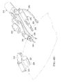
- FIG. 1A is illustration of a perspective view of an example embodiment of an external anchor
- FIG. 1B is another illustration of a perspective view of an example embodiment of an external anchor attached to an example embodiment of a port assembly
- FIG. 2A is an illustration of a perspective view of an example embodiment of a surgical device configured in a reverse-directed position with one port assembly, one instrument arm assembly, and one image capturing assembly;
- FIG. 2B is an illustration of a perspective view of an example embodiment of a surgical device configured in a forward-directed position with one port assembly, one instrument arm assembly, and one image capturing assembly;
- FIG. 3A is another illustration of a perspective view of another example embodiment of a surgical device configured in a reverse-directed position with one port assembly, one instrument arm assembly, and one image capturing assembly;
- FIG. 3B is another illustration of a perspective view of another example embodiment of a surgical device configured in a forward-directed position with one port assembly, one instrument arm assembly, and one image capturing assembly;
- FIG. 4A is an illustration of a perspective exploded view of an example embodiment of a port assembly
- FIG. 4B is an illustration of a side view of an example embodiment of a port assembly
- FIG. 4C is an illustration of a cross-sectional view of an example embodiment of a port assembly with a first or second gate assembly in the open position;
- FIG. 4D is an illustration of a cross-sectional view of an example embodiment of a port assembly with a first or second gate assembly in the closed position;
- FIG. 5A is an illustration of a side view of an example embodiment of an instrument arm assembly
- FIG. 5B is another illustration of a side view of an example embodiment of an instrument arm assembly
- FIG. 5C is an illustration of a perspective view of an example embodiment of an instrument arm assembly
- FIG. 5D is an illustration of a side view of an example embodiment of an end-effector assembly secured to an arm assembly
- FIG. 5E is an illustration of a side cross-sectional view of an example embodiment of an end-effector assembly secured to an arm assembly;
- FIG. 5F is an illustration of a side view of an example embodiment of an end-effector assembly unsecured from an arm assembly
- FIG. 5G is an illustration of a side cross-sectional view of an example embodiment of an end-effector assembly unsecured from an arm assembly;
- FIG. 5H is an illustration of a perspective view of an example embodiment of an end-effector assembly
- FIG. 5I is an illustration of a perspective view of an example embodiment of an instrument with an insulative portion
- FIG. 5J is an illustration of a top cross-sectional view of an example embodiment of an arm assembly
- FIG. 5K is an illustration of a perspective view of an example embodiment of an arm assembly
- FIG. 5L is an illustration of a side view of an example embodiment of an instrument arm assembly
- FIG. 5M is an illustration of a side cross-sectional view of an example embodiment of an instrument arm assembly
- FIG. 5N is an illustration of a top cross-sectional view of an example embodiment of a second arm assembly
- FIG. 5O is an illustration of a transparent perspective partial view of an example embodiment of an instrument arm assembly
- FIG. 6A is an illustration of a perspective view of an example embodiment of an image capturing assembly
- FIG. 6B is an illustration of a cross sectional view of another example embodiment of an image capturing assembly having an internal temperature control assembly
- FIG. 6C is an illustration of perspective views of another example embodiment of an image capturing assembly having internal temperature control assemblies
- FIG. 6D is an illustration of a perspective view of the system in operation in a cavity of a patient, including a second image capturing assembly;
- FIG. 7 is a flow diagram of an exemplary method for configuring a surgical device
- FIGS. 8A-E are illustrations of a side view of an example embodiment of a method of configuring a surgical device in a forward-directed position
- FIGS. 8F-K are illustrations of a side view of an example embodiment of a method of configuring a surgical device in a reverse-directed position
- FIG. 9A is an illustration of a perspective view of an example embodiment of a surgical device system
- FIG. 9B is an illustration of a perspective view of another example embodiment of a surgical device system.
- FIG. 10A is an illustration of a perspective view of an example embodiment of an external anchor.
- FIG. 10B is an illustration of a perspective view of another example embodiment of an external anchor.
- Example embodiments will now be described with reference to the accompanying drawings, which form a part of the present disclosure, and which illustrate example embodiments which may be practiced.
- the terms “example embodiment,” “exemplary embodiment,” and “present embodiment” do not necessarily refer to a single embodiment, although they may, and various example embodiments may be readily combined and/or interchanged without departing from the scope or spirit of example embodiments.
- the terminology as used in the present disclosure and the appended claims is for the purpose of describing example embodiments only and is not intended to be limitations.
- the term “in” may include “in” and “on,” and the terms “a,” “an” and “the” may include singular and plural references.
- the term “by” may also mean “from,” depending on the context.
- the term “if” may also mean “when” or “upon,” depending on the context.
- the words “and/or” may refer to and encompass any and all possible combinations of one or more of the associated listed items.
- surgical robotic systems including surgical robotic arms (and those instruments attached to them), developed for performing robotic-assisted MIS surgical procedures also suffer from one or more problems.
- a major technical challenge for a surgical robotic system is the difficulty in providing sufficient anchoring and/or reactive forces to stabilize against forces that are desired and/or necessary to be applied to the patient by the surgical robotic system during a surgical action.
- certain surgical actions for known surgical robotic systems may require tremendous effort and time, and may not be performed properly or at all as a result of the problem of insufficient anchoring and/or reactive forces.
- Another example of a problem recognized in the present disclosure as being encountered by surgical robotic systems is the difficulty in providing an instrument, such as a cutting and/or gripping instrument attached to the end of a surgical robotic arm, with access to all or even most parts, areas, and quadrants of an abdominal cavity of a patient after the surgical robotic system has been set up (or installed) and is ready to perform a surgery. That is, after the surgical robotic arm of the system has been inserted, attached, and properly set up in the abdominal cavity of the patient and is ready to perform a surgical action, the instrument attached to the end of the surgical robotic arm is typically limited to access only certain parts, areas, and quadrants of the abdominal cavity of the patient.
- Surgical systems, devices, and methods including those for use in MIS and natural orifice transluminal endoscopic surgery (or NOTES), are described in the present disclosure for addressing one or more problems of known surgical systems, devices, and methods, including those described above and in the present disclosure. It is to be understood that the principles described in the present disclosure can be applied outside of the context of MIS and/or NOTES, such as performing scientific experiments and/or procedures in environments that are not readily accessible by humans, including in a vacuum, in outer space, and/or under toxic and/or dangerous conditions, without departing from the teachings of the present disclosure.
- the Surgical System (e.g., Surgical Device 200 )
- FIG. 2A and FIG. 2B An illustration of an example embodiment of a surgical device or system (e.g., surgical device or system 200 ) operable to be inserted into an abdominal cavity of a patient through a single access or opening (e.g., a single incision (such as an incision in or around the umbilical area) or through a natural orifice (such as a rectum or vagina, for performing natural orifice transluminal endoscopic surgery (or NOTES), hereinafter referred to as an “opening”) of the patient is depicted in FIG. 2A and FIG. 2B .
- the surgical device may then be anchored so as to position the surgical device 200 in the opening.
- the surgical device 200 may comprise a port assembly 210 and an instrument arm assembly 230 .
- the surgical device 200 may also comprise other elements, such as one or more other instrument arm assemblies, one or more image capturing assemblies, one or more assistant arm assemblies, etc.
- the surgical device 200 may be provided with an external anchor 1 attachable to the port assembly 210 .
- the external anchor 1 may comprise a configurable assembly of segments 2 , 6 , 10 , and 14 in communication with one another via joints or connecting portions 4 , 8 , and 12 , and external anchor connector 16 .
- the external anchor 1 may be operable to securely fix the position and/or orientation (hereinafter “position”) of the port assembly 210 in or about the single opening of the patient, and may also be operable to provide sufficient anchoring and/or reactive forces to stabilize against forces desired and/or necessary to be applied by at least one or more elements of the surgical device 200 , including the instrument arm assembly 230 , during a surgical action or procedure.
- the external anchor 1 which may also be in the form of the controllable swivel assembly 1000 illustrated in FIG. 10A and FIG. 10B , may be operable to cooperate with the port assembly 210 to provide one or more in vitro degrees of freedom.
- the external anchor 1 may be configurable to provide 3 in vitro degrees of freedom.
- the one or more in vitro degrees of freedom may include a torsional movement, pivotal movement, telescopic movement, and/or other movements of the port assembly 210 relative to the external anchor 1 .
- a torsional movement of the port assembly 210 as illustrated by arrow A in FIG.
- 1B may allow one or more attached instruments, including an instrument arm assembly 230 , to re-position during a surgical procedure (i.e. after set up or installation) so as to access other parts, areas, and/or all quadrants of the abdominal cavity of the patient.
- a pivotal movement of the port assembly 210 as illustrated by arrow B in FIG. 1B , may allow the port assembly 210 to be positioned in one of a plurality of angles with respect to opening of the patient, and may also allow attached instruments, including the instrument arm assembly 230 , to re-position during a surgical procedure (i.e. after set up or installation) so as to access distal areas of the abdominal cavity of the patient.
- the other joint portions of the external anchor 1 may also be operable to cooperate and/or assist in desired movements of the port assembly 210 .
- the external anchor 1 may be anchored to one or more stationary or fixedly positioned objects, such as a side rail 300 of a surgical table/bed illustrated in FIG. 1A .
- FIGS. 10A and 10B illustrate other example movements that provide for additional in vitro degrees of freedom via an example embodiment of the external anchor (controllable swivel assembly) 1000 .
- the controllable swivel assembly 1000 will be further described below in at least the section “(1) Providing the external anchor and installing the port assembly.”
- the surgical device 200 may further comprise one or more additional instrument arm assemblies, such as a second instrument arm assembly 240 illustrated in FIGS. 3A and 3B , attachable to the port assembly 210 .
- additional instrument arm assemblies such as a second instrument arm assembly 240 illustrated in FIGS. 3A and 3B , attachable to the port assembly 210 .
- One or more of the instrument arm assemblies including the first instrument arm assembly 230 , the second instrument arm assembly 240 , a third instrument arm assembly (not shown), a fourth instrument arm assembly (not shown), etc., may be attachable or securable to the port assembly 210 .
- Such instrument arm assemblies may be operable to access and perform one or more surgical actions in/on any and all parts, areas, and/or quadrants within a cavity of the patient.
- surgical device 200 may be configurable to perform surgical actions in a forward direction (or “forward-directed position” or “forward position”) (e.g., as illustrated in FIGS. 2B and 3B ).
- surgical device 200 may be configurable to perform surgical actions in a reverse direction (or “reverse-directed position” or “reverse position”) (e.g., as illustrated in FIGS. 2A and 3A ).
- the surgical device 200 may also comprise one or more image capturing assemblies, such as image capturing assembly 220 .
- the surgical device 200 may further comprise one or more assistant arm assemblies, such as a retractor arm assembly 250 , as illustrated in FIGS. 2A, 2B, 3A, and 3B .
- the surgical device 200 may comprise one or more other instrument arm assemblies, such as suction/irrigation assembly 260 , illustrated in FIGS. 2A, 2B, 3A, and 3B , that can be inserted into the opening of the patient via the port assembly 210 before, during, and/or after performing a surgical action or procedure.
- the surgical device 200 may be configurable in a plurality of configurations and arrangements, including having more or less than two instrument arm assemblies (such as third, fourth, fifth, etc. instrument arm assemblies), more than one image capturing assembly (such as second, third, etc. image capturing assemblies), more or less than one assistant arm assembly (such as second, third, etc. assistant arm assemblies), and/or more or less than one other laparoscopic tool in example embodiments without departing from the teachings of the present disclosure.
- instrument arm assemblies such as third, fourth, fifth, etc. instrument arm assemblies
- image capturing assembly such as second, third, etc. image capturing assemblies
- assistant arm assembly such as second, third, etc. assistant arm assemblies
- the Port Assembly (e.g., Port Assembly 210 )
- FIGS. 2A, 2B, 3A, 3B , FIG. 4A , FIG. 4B , FIG. 4C , and FIG. 4D An example embodiment of the port assembly (e.g., port assembly 210 ) is illustrated in FIGS. 2A, 2B, 3A, 3B , FIG. 4A , FIG. 4B , FIG. 4C , and FIG. 4D .
- the port assembly 210 may be configurable to be inserted in or about a single opening of the patient (such as a single incision or a natural orifice) and fixed in position by at least the external anchor (such as the external anchor 1 illustrated in FIGS. 1A and 1B and the controllable swivel assembly 1000 illustrated in FIGS. 10A and 10B ).
- the port assembly 210 may be an elongated structure having a central access channel 210 a formed through the port assembly 210 .
- the central access channel 210 a may be for use in inserting and removing instruments, such as one or more instrument arm assemblies 230 , 240 , one or more image capturing assemblies 220 , one or more assistant arm assemblies 250 , 260 , etc.
- the port assembly 210 may include a first end section 212 and a second end section 214 .
- the first end section 212 and second end section 214 may be fixably attachable to one another or formed as a unitary article.
- the port assembly 210 may also include a mid section 213 between the first end section 212 and the second end section 214 .
- the first end section 212 , second end section 214 , and mid section 213 may be fixably attachable to one another, as illustrated in FIGS. 4A and 4B , or two or more of these sections may be formed as a unitary article.
- the first end section 212 may be the portion of the port assembly 210 that is secured to the external anchor 1 , and the port assembly 210 may be fixed in position at an angle ⁇ relative to the singe opening of the patient of between about 0 to +/ ⁇ 90 degrees.
- the port assembly 210 may comprise a first end section 212 .
- the first end section 212 may have a first end channel 212 a formed through the first end section 212 .
- the first end channel 212 a may be considered as a part of the central access channel 210 a .
- the first end section 212 may also include a portion operable to be secured to the external anchor 1 , such as a portion on an exterior portion of the first end section 212 .
- the first end section 212 may also include a first gate assembly 212 b , as illustrated in FIGS. 4A, 4C, and 4D .
- the first gate assembly 212 may be configurable to control access through the first end channel 212 a .
- the first gate assembly 212 b may be configurable to be in an open position, as illustrated in FIG. 4C , so as to allow access through the first end channel 212 a .
- the first gate assembly 212 b may also be configurable to be in a closed position, as illustrated in FIG. 4D , so as to prevent or restrict access through the first end channel 212 a .
- the first gate assembly 212 b may also be configurable to be in a partially closed (or partially opened) position (not shown).
- the first gate assembly 212 b may also be configurable to transition between the closed position and the open position.
- the first gate assembly 212 b may be provided within the first end section 212 in such a way that, when the first gate assembly 212 b is configured to be in the open position, as illustrated in FIG. 4C , the first end channel 212 a is substantially or completely unobstructed by the first gate assembly 212 b .
- the first gate assembly 212 b may be configured to be in the open position when a surgeon desires to insert (or remove) an instrument into (or out of) the cavity of the patient via the first end channel 212 a (and the rest of the central access channel 210 a ).
- first gate assembly 212 b may be provided within the first end section 212 in such a way that, when the first gate assembly 212 b is configured to be in the closed position, as illustrated in FIG. 4D , the first end channel 212 a is substantially or completely obstructed by the first gate assembly 212 b .
- the first gate assembly 212 b may be configured to be in the closed position when a surgeon desires to maintain an insufflation of the cavity of the patient and/or when the surgeon does not need to insert (or remove) an instrument into (or out of) the cavity of the patient via the first end channel 212 a.
- the first gate assembly 212 b may include a first expandable portion 212 b configurable to expand when the first gate assembly 212 b is configured to the closed position, as illustrated in FIG. 4D .
- the first expandable portion 212 b may be operable to substantially or completely block, among other things, a gas medium (and/or other medium) from passing through the first end channel 212 a .
- the first gate assembly 212 b i.e., the first expandable portion 212 b
- the first gate assembly 212 b may be configurable to substantially prevent the carbon dioxide gas from leaving the cavity of the patient through the first end channel 212 a.
- the first expandable portion 212 b may include one or more first expandable members.
- the first expandable portion 212 b may include six expandable members, as illustrated in FIGS. 4C and 4D . It is to be understood that the first expandable portion 212 b may include more or less than six expandable members without departing from the teachings of the present disclosure.
- Some or all of the first expandable members may be integrated together and/or in communication with one another, such as in a manner where some or all of the first expandable members are operable to receive pressure (i.e., gas medium) from a common or same first source 212 b ′.
- the first source 212 b ′ may be configurable to provide a positive pressure (i.e., a supply of gas) so as to cause some or all of the first expandable members to expand and block the first end channel 212 a (e.g., hermetically block the first end channel 212 a ).
- a positive pressure i.e., a supply of gas
- the first source 212 b ′ may be configurable to provide a negative pressure (i.e., remove gas) so as to cause one or more (or all) of the first expandable members to not expand (and/or contract) and unblock the first end channel 212 a .
- a negative pressure i.e., remove gas
- the first gate assembly 212 b may also include a valve (not shown), or the like, in addition to or in replacement of the first expandable portion 212 b .
- the valve may be configurable to perform substantially the same actions of blocking the first end channel 212 a when the first gate assembly 212 b is configured to the closed position and unblocking the first end channel 212 a when the first gate assembly 212 b is configured to the open position.
- the valve may be any type of valve configurable to perform the actions described above and in the present disclosure.
- the valve may include, but is not limited to including, a ball valve, gate valve, etc., so long as the valve is configurable to substantially block/unblock the first end channel 212 a and prevent a gas medium from passing through the first end channel 212 a.
- the port assembly 210 may also include the second end section 214 , as illustrated in at least FIGS. 4A and 4B .
- the second end section 214 may have a second end channel 214 a formed through the second end section 214 .
- the second end channel 214 a may be substantially or completely aligned with the first end channel 212 a .
- the second end channel 214 a as well as the first end channel 212 a , may be considered as a part of the central access channel 210 a in example embodiments.
- the second end section 214 may also include an insufflation port (not shown) for use in providing insufflation to the cavity of the patient.
- the second end section 214 may also include a second gate assembly 214 , as illustrated in FIGS. 4A, 4C, and 4D .
- the second gate assembly 214 may be configurable to control access through the second end channel 214 a .
- the second gate assembly 214 b may be configurable to be in an open position, as illustrated in FIG. 4C , so as to allow access through the second end channel 214 a .
- the second gate assembly 214 b may also be configurable to be in a closed position, as illustrated in FIG. 4D , so as to prevent or restrict access through the second end channel 214 a .
- the second gate assembly 214 b may also be configurable to be in a partially closed (or partially opened) position (not shown).
- the second gate assembly 214 b may also be configurable to transition between the closed position and the open position.
- the second gate assembly 214 b may be provided within the second end section 212 in such a way that, when the second gate assembly 214 b is configured to be in the open position, as illustrated in FIG. 4C , the second end channel 214 a is substantially or completely unobstructed by the second gate assembly 214 b .
- the second gate assembly 214 b may be configured to be in the open position when a surgeon desires to insert (or remove) an instrument into (or out of) the cavity of the patient via the second end channel 214 a (and the rest of the central access channel 210 a ).
- the second gate assembly 214 b may be provided within the second end section 214 in such a way that, when the second gate assembly 214 b is configured to be in the closed position, as illustrated in FIG. 4D , the second end channel 214 a is substantially or completely obstructed by the second gate assembly 214 b .
- the second gate assembly 214 b may be configured to be in the closed position when a surgeon desires to maintain an insufflation of the cavity of the patient and/or when the surgeon does not need to insert (or remove) an instrument into (or out of) the cavity of the patient via the second end channel 214 a.
- the second gate assembly 214 b may include a second expandable portion 214 b configurable to expand when the second gate assembly 214 b is configured to the closed position, as illustrated in FIG. 4D .
- the second expandable portion 214 b may be operable to substantially or completely block, among other things, a gas medium (and/or other medium) from passing through the second end channel 214 a .
- the second gate assembly 214 b (i.e., the second expandable portion 214 b ) may be configurable to substantially prevent the carbon dioxide gas from leaving the cavity of the patient through the second end channel 214 a.
- the second expandable portion 214 b may include one or more second expandable members.
- the second expandable portion may include six expandable members, as illustrated in FIGS. 4C and 4D . It is to be understood that the second expandable portion 214 b may include more or less than six expandable members without departing from the teachings of the present disclosure.
- Some or all of the second expandable members may be integrated together and/or in communication with one another, such as in a manner where some or all of the second expandable members are operable to receive pressure (i.e., gas medium) from a common or same second source 214 b ′.
- the second source 214 b ′ may be configurable to provide a positive pressure (i.e., a supply of gas) so as to cause some or all of the second expandable members to expand and block the second end channel 214 a (e.g., hermetically block the second end channel 214 a ).
- a positive pressure i.e., a supply of gas
- the second source 214 b ′ may be configurable to provide a negative pressure (i.e., remove gas) so as to cause some or all of the second expandable members to not expand (and/or contract) and unblock the second end channel 214 a .
- more than one second sources 214 b ′ may provide the positive pressure and negative pressure to the one or more expandable members without departing from the teachings of the present disclosure. It is also to be understood in the present disclosure that one or more of the first sources 212 b ′ and one or more of the second sources 214 b ′ may be the same or different sources.
- the second gate assembly 214 b may also include a valve (not shown), or the like, in addition to or in replacement of the second expandable portion 214 b .
- the valve may be configurable to perform substantially the same actions of blocking the second end channel 214 a when the second gate assembly 214 b is configured to the closed position and unblocking the second end channel 214 a when the second gate assembly 214 b is configured to the open position.
- the valve may be any type of valve configurable to perform the actions described above and in the present disclosure.
- the valve may include, but is not limited to including, a ball valve, gate valve, etc., so long as the valve is configurable to substantially block/unblock the second end channel 214 a and prevent a gas medium from passing through the second end channel 214 a.
- the second end section 214 may also include one or more anchor ports 216 , as illustrated in FIGS. 4A and 4B .
- Each of the anchor ports 216 may be operable to enable an instrument arm assembly 230 or 240 , image capturing assembly 220 , and/or assistant arm assemblies 250 or 260 to be secured to and unsecured from the port assembly 210 .
- Each of the anchor ports 216 may be formed in any one or more of a plurality of shapes, holes, slots, indentations, protrusions, hooks, fasteners, magnets, buckles, or the like, including those described above and in the present disclosure.
- one or more of the anchor ports 216 may include one or more slots, or the like, operable to allow a shoulder section 231 of an instrument arm assembly 230 or 240 to be inserted into and attached.
- the port assembly 210 may also include the mid section 213 , as illustrated in at least FIGS. 4A and 4B .
- the mid section 213 may have a mid section channel 213 a formed through the mid section 213 .
- the mid section channel 213 a may be substantially or completely aligned with the first end channel 212 a and/or the second end channel 214 a .
- the mid section channel 213 a as well as the first end channel 212 a and/or the second end channel 214 a , may be considered as a part of the central access channel 210 a in example embodiments.
- the mid section 213 may also include an insufflation port (not shown) in addition to or in replacement of the insufflation port (not shown) of the second end section 214 .
- the mid section 213 may also include a mid section gate assembly (not shown) similar to that of the first gate assembly 212 and second gate assembly 214 described above and in the present disclosure.
- the mid section channel 213 a may be operable to cooperate with the first gate assembly 212 b and the second gate assembly 214 b to function as or like an isolation chamber for instruments, such as the instrument arm assembly 230 or 240 , image capturing assembly 220 , assistant arm assembly 250 or 260 , etc.
- the first gate assembly 212 b may be configured to the open position to allow the instrument to be inserted into the mid section channel 213 a .
- the first gate assembly 212 b may be configured to the closed position.
- the second gate assembly 214 b may then be configured to the open position to allow the instrument to be further inserted through the port assembly 210 .
- the second gate assembly 214 b may be configured to the closed position.
- the central access channel 210 a may include or be formed by the first end channel 212 a , the second end channel 214 a , and/or the mid section channel 213 a .
- the central access channel 210 a may be operable to provide an access port (i.e. a passageway or channel) to allow an insertion (or removal) of one or more instruments, such as one or more instrument arm assemblies 230 or 240 , one or more image capturing assemblies 220 , one or more assistant arm assemblies 250 or 260 , etc.
- first end section 212 , the second end 214 , and/or the mid section 213 may be substantially cylindrical in shape.
- the first end section 212 , the second end section 214 , and/or the mid section 213 may also be formed in any one of a plurality of other shapes, sizes, and/or dimensions without departing from the teachings of the present disclosure.
- an outer diameter of the first end section 212 , the second end 214 , and/or the mid section 213 may be between about 28 to 35 mm and an inner diameter (unblocked) of the first end section 212 , the second end 214 , and/or the mid section 213 may be between about 16 to 21 mm.
- the outer diameter of the first end section 212 , the second end 214 , and/or the mid section 213 may be about 33 mm and the inner diameter (unblocked) of the first end section 212 , the second end 214 , and/or the mid section 213 may be about 19 mm.
- the length of the first end section 212 may be between about 80 to 100 mm
- the length of the second end section 214 may be between about 80 to 200 mm
- the length of the mid section 213 may be between about 60 to 80 mm.
- the overall length of the port assembly 210 may be between about 320 to 380 mm. It is to be understood in the present disclosure that the above dimensions are merely an illustration of example embodiments, and as such the dimensions may be smaller or larger than those recited above without departing from the teachings of the present disclosure.
- the port assembly 210 may be formed using any one or more of a plurality of materials, such as surgical-grade metals, high-strength aluminum alloys, stainless steel (such as 304/304L, 316/316L, and 420), pure titanium, titanium alloys (such as Ti6Al4V, NiTi), and cobalt-chromium alloys.
- the first gate assembly 212 b and the second gate assembly 214 b may be formed using any one or more of a plurality of materials, such as bio-compatible materials (such as silicone rubber and polyurethane).
- the Image Capturing Assembly (e.g., Image Capturing Assembly 220 )
- the surgical device 200 may comprise one or more image capturing assemblies (e.g., image capturing assembly 220 ) configurable to be inserted into and attach to the port assembly 210 .
- One or more of the image capturing assemblies 220 may comprise at an image capturing body 224 , a multi-curvable body 222 , and an anchoring portion 220 a.
- the image capturing body 224 may include one or more cameras 227 .
- Each camera 227 may include a standard and/or high definition 2-dimensional (2D) and/or 3-dimensional (3D) camera operable to capture imaging, such as 2D and/or stereoscopic and/or autostereoscopic 3D imaging, including images, video, and/or audio, and provide in real-time via wired and/or wireless communication the captured imaging, including images, video, and/or audio, to the computing device (or controller or system) of one or more nearby and/or remotely located surgical teams 904 , as described above and in the present disclosure.
- 2D 2-dimensional
- 3D 3-dimensional
- the computing device may comprise one or more processors, one or more computer-human interfaces, one or more graphical displays (such as computer screens, television screens, portable devices, wearable devices such as glasses, etc.), and/or other devices and/or systems, an example of which is illustrated in FIGS. 9A and 9B .
- the one or more nearby and/or remotely located surgical teams 904 may be operable to view, hear, sense, analyze, and control (such as pan, zoom, process, adapt, mark, change resolution, etc.) the imaging displayed or represented on one or more standard and/or high definition 2D and/or 3D graphical displays 902 , such as shown in the illustration of FIGS.
- the image capturing body 224 may also comprise one or more illumination sources 229 , such as an LED, or the like, operable to illuminate or sense at least one or more parts, sections, and/or quadrants of the cavity of the patient, including instruments provided in the cavity of the patient.
- the image capturing body 224 may further comprise one or more internal temperature control assemblies operable to control (such as reduce) the temperature of one or more components of the image capturing body 224 .
- one or more of the image capturing assemblies 220 may comprise a multi-curvable body 222 attached to the image capturing body 224 .
- the multi-curvable body 222 may be any elongated multi-curvable, multi-bendable, multi-articulable, and/or snake-like (hereinafter “multi-curvable”) body that can be controlled/configured by the surgical team (such as via the computing device/controller) to, among other things, straighten and/or curve (and hold such a straightness and/or curvature) at one or more of a plurality of locations along the multi-curvable body 222 , curve (and hold such a curvature) in one or more of a plurality of curvatures, and/or straighten and/or curve (and hold such a straightness and/or curvature) in one or more of a plurality of directions.
- the multi-curvable body 222 may be controllable/configurable by the surgical team (such as via the computing device/controller) to curve at two different locations 222 a and 222 b along the multi-curvable body 222 , and each of the curves may include any curvature and in any direction. It is to be understood that the multi-curvable body 222 may be configurable to curve in more or less than two locations along the multi-curvable body 222 without departing from the teachings of the present disclosure.
- the multi-curvable body 222 when configured to curve at any location along the multi-curvable body 222 , the curve may be held and/or released (or configured to uncurve, curve less, or straighten) by the surgical team (such as via the computing device/controller).
- the multi-curvable body 222 may be formed in any one or more ways known in the art including.
- the multi-curvable body 222 may include a plurality of segments, each segment linked to an adjacent segment in such a way that the segment may be controlled/configured to be pivotally positioned in a plurality of positions relative to the adjacent segment.
- the multi-curvable body 222 may include a plurality of wires, cables, or the like, distributed throughout the multi-curvable body 222 in such a way that a pulling/releasing, shortening/lengthening, tightening/loosening, etc.
- the multi-curvable body 222 may include a plurality of springs, gears, motors, etc. for achieving the above-mentioned curving. It is to be understood in the present disclosure that the multi-curvable body 222 may also include a combination of one or more of the above-mentioned approaches.
- One or more internal temperature control assemblies may be provided for each image capturing assembly 220 .
- Each internal temperature control assembly may be operable to control (such as reduce) the temperature and/or heat emission of the aforementioned camera(s) 227 , illumination source(s) 229 , and/or multi-curvable body 222 .
- the one or more internal temperature control assemblies may be operable to perform such temperature control using one or more gases, liquids, and/or solids.
- the gases and/or liquids may be fed, maintained, and/or regulated using an external source via one or more tubes, or the like.
- the one or more tubes used to provide, regulate, and/or discharge the gases and/or liquids may have a diameter between about 0.5 mm to 3 mm in example embodiments, but the dimensions of such tubes may also be more or less. It is to be understood in the present disclosure that the one or more tubes (if used), as well as any solids (if used), may be provided through an interior of the image capturing assembly 220 without increasing dimensions (such as diameter) of the image capturing assembly 220 and/or affecting the controllability/configurability of the multi-curvable body 222 .
- example embodiments may also be operable to provide such gases into the body cavity and/or discharge or recycle such gases outside of the body cavity via one or more tubes, or the like.
- the gases may comprise carbon dioxide, oxygen, and/or other gases in example embodiments. Such gases may be further operable to assist in providing and/or maintaining insufflation of the cavity of the patient during a surgical procedure.
- example embodiments may be operable to discharge or recycle such liquids outside of the body cavity.
- the internal temperature control assembly When the internal temperature control assembly utilizes solids, or the like, such solids may possess properties that enable the surgical team to change the temperature of the solids, such as by applying electricity or other form of energy, so as to control (such as reduce) the temperature and/or heat emission of one or more components of the image capturing assembly 220 .
- the internal temperature control assembly may utilize a combination of gases, liquids, solids, and/or the like without departing from the teachings of the present disclosure.
- the image capturing assembly 220 may be secured to the port assembly 210 in one or more of a plurality of ways, including those described above and in the present disclosure for the instrument arm assemblies 230 or 240 and/or the assistant arm assemblies 250 or 260 .
- the image capturing assembly 220 may also comprise an anchoring portion 220 a (e.g., similar to the securing portion 231 a of the instrument arm assembly 220 ) operable to attach (or secure) the image capturing assembly 220 to one or more anchor ports 216 of the port assembly 210 .
- the image capturing body 224 and the multi-curvable body 222 may each be substantially cylindrical in shape.
- the image capturing body 224 and the multi-curvable body 222 may also be formed in any one of a plurality of other shapes, sizes, and/or dimensions without departing from the teachings of the present disclosure.
- the length of the multi-curvable body 222 may be between about 50 to 150 mm.
- a length of multi-curvable body 222 may also be adjustable by the surgical team 904 before, during, and/or after insertion of the camera arm assembly into the cavity of the patient.
- the outer diameter of the multi-curvable body 222 may be between about 5 to 7 mm. It is to be understood in the present disclosure that the above dimensions are merely an illustration of example embodiments, and as such the dimensions may be smaller or larger than those recited above without departing from the teachings of the present disclosure.
- the multi-curvable body 222 may be formed using any one or more of a plurality of materials, such as stainless steel, etc. It is to be understood in the present disclosure that other materials may also be used without departing from the teachings of the present disclosure. It is to be understood in the present disclosure that the above materials are merely an illustration of example embodiments, and these and other materials and compositions may be used without departing from the teachings of the present disclosure.
- the image capturing assembly 220 may further comprise a gas shield 228 located nearby one or more lenses of the camera 227 .
- the image capturing assembly 220 may further comprise a gas shield 228 located nearby one or more of the illumination sources 229 and/or any other sensors (such as temperature sensors, pressure sensors, humidity sensors, etc.) provided by the image capturing assembly 220 .
- the gas shield 228 may comprise one or more openings or the like, one or more external gas sources 228 , and one or more tubes, channels, or the like, between the one or more external gas sources and the one or more openings of the gas shield 228 .
- the gas shield 228 may be operable to provide pressurized gases (and/or liquids), such as carbon dioxide, oxygen, other gases or liquids, or combinations thereof, via the one or more openings of the gas shield 228 to an area in front of the camera 227 (as well as in front of the illumination sources 229 and/or other sensors).
- pressurized gases such as carbon dioxide, oxygen, other gases or liquids, or combinations thereof
- the overall system may also include one or more separate image capturing assemblies, such as the separate image capturing assembly 320 illustrated in FIG. 6D .
- the separate image capturing assembly 320 may be magnetically anchored by a magnetic anchor 310 to an internal wall of the cavity of the patient, such as via a permanent magnet, electromagnet, or the like.
- the magnetic anchor 310 may also be secured/held in position via an external anchor (not shown).
- the separate image capturing assembly 320 may include one or more cameras 327 , and may also include one or more illumination sources 329 .
- the separate image capturing assembly 320 may be operable to provide one or more of a variety of views, including, but not limited to, a normal view, zoomed view, wide-angled view, and/or panoramic view of the cavity of the patient.
- the separate image capturing assembly 320 may be positioned in such a way as to provide the surgical team 904 with an unobstructed view of areas of interest within the cavity of the patient. In respect to positioning and securing the separate image capturing assembly 320 in place, as illustrated in FIG.
- the separate image capturing assembly 320 may be inserted through the central access channel 210 a of the port assembly 210 and to the desired location of the interior wall of the cavity of the patient in one or more of a plurality of ways, including using a surgical tool (not shown), attaching the separate image capturing assembly 320 to a multi-curvable body (not shown) similar to that of the image capturing assembly 220 (as illustrated in FIGS. 2A, 2B, 3A, 3B, and 6D ), etc.
- the Instrument Arm Assembly (e.g., Instrument Arm Assembly 230 , 240 )
- the surgical device 200 may comprise one or more instrument arm assemblies (e.g., first instrument arm assembly 230 , second instrument arm assembly 240 , third instrument arm assembly (not shown), fourth instrument arm assembly (not shown), etc.), each configurable to attach to the port assembly 210 .
- instrument arm assemblies e.g., first instrument arm assembly 230 , second instrument arm assembly 240 , third instrument arm assembly (not shown), fourth instrument arm assembly (not shown), etc.
- One or more of the instrument arm assemblies may comprise a configurable serial (or linear) arrangement of a plurality of instrument arm segments (or arm assemblies, such as a first arm assembly 330 , second arm assembly 360 , and shoulder assembly 231 illustrated in at least FIG. 5C ) and joint portions (such as a first arm assembly joint portion 350 , first shoulder joint portion 370 , and second shoulder joint portion 380 illustrated in at least FIG. 5L and FIG. 5M ), and at least one end instrument (or end effector) 239 , 342 , 344 integrated into and/or connected to one or more of the instrument arm segments and/or joint portions.
- the end effector 239 , 342 , 344 may be any instrument suitable for use in surgical procedures, such as a cutting and/or gripping instrument.
- One or more of the instrument arm assemblies (such as 230 , 240 ) may also comprise one or more illumination sources (not shown), such as an LED, or the like, operable to illuminate one or more parts of the end effector 239 , 342 , 344 , instrument arm assemblies, and/or parts, sections, and/or quadrants of the abdominal cavity of the patient.
- One or more of the instrument arm assemblies may also comprise one or more integrated motors (e.g., integrated motors 332 , 334 , 336 , 339 illustrated in at least FIG. 5E , FIG. 5G , FIG. 5J , and FIG. 5K and integrated motors 362 , 364 , and 366 illustrated in at least Figure M, FIG. 5N , and FIG. 5O ) operable to provide at least one degree of freedom for the instrument arm assembly.
- Each integrated motor e.g., integrated motors 332 , 334 , 336 , 339 illustrated in at least FIGS.
- 5E, 5G, 5J, and 5K and integrated motors 362 , 364 , and 366 illustrated in at least FIG. 5M-O may be fully and independently functioning motors that are housed entirely (with the exception of, for example, power and/or control cables, which may be fed via the port assembly) in an instrument arm segment (or arm assembly, such as the first arm assembly 330 , second arm assembly 360 , and shoulder assembly 231 ), such as housing 330 ′ and 360 ′.
- One or more of the instrument arm assemblies may also include an integrated haptic and/or force feedback subsystem (not shown) in communication with one or more of the integrated motors and/or other sensors and/or instruments operable to provide to the surgical team (such as via computing device/controller) with one or more of a plurality of feedback responses and/or measurements, including those pertaining to position (including orientation), applied force, proximity, temperature, pressure, humidity, etc., of, by, and/or nearby to the instrument arm assembly.
- an integrated haptic and/or force feedback subsystem (not shown) in communication with one or more of the integrated motors and/or other sensors and/or instruments operable to provide to the surgical team (such as via computing device/controller) with one or more of a plurality of feedback responses and/or measurements, including those pertaining to position (including orientation), applied force, proximity, temperature, pressure, humidity, etc., of, by, and/or nearby to the instrument arm assembly.
- the surgical team 904 may be provided with a master input device having manipulators, or the like, having haptic and/or force feedback and designed to map and sense the surgical team's 904 delicate finger-twisting, wrist-bending, and/or other arm/shoulder movements into movements of the instrument arm (such as 230 , 240 ) with high precision, high dexterity, and minimum burden, while also providing feedback of contact resistance (such as tissue resistance).
- a master input device having manipulators, or the like, having haptic and/or force feedback and designed to map and sense the surgical team's 904 delicate finger-twisting, wrist-bending, and/or other arm/shoulder movements into movements of the instrument arm (such as 230 , 240 ) with high precision, high dexterity, and minimum burden, while also providing feedback of contact resistance (such as tissue resistance).
- an instrument arm assembly (such as 230 , 240 ) comprises one or more illumination sources, cameras, haptic and/or force feedback instruments, and/or other sensors and/or instruments, as described above and in the present disclosure
- the instrument arm assembly may also comprise a gas shield, such as the gas shield described above for the image capturing assembly 220 .
- One or more of the instrument arm assemblies (such as 230 , 240 ) may further comprise one or more internal temperature control assemblies operable to control (such as reduce or increase) the temperature of one or more components of the instrument arm assembly.
- each of the instrument arm assemblies may comprise a first instrument arm segment (or shoulder section) 231 , a second instrument arm segment (or first arm section) 233 (as illustrated in at least FIGS. 5A-B ), 360 (as illustrated in at least FIG. 5C ), a third instrument arm segment (or second arm section) 235 (as illustrated in at least FIGS. 5A-B ), 330 (as illustrated in at least FIG. 5C ), and a fourth instrument arm segment (or hand section) 237 .
- the instrument arm assembly 230 may also comprise a first joint portion (or shoulder joint section) 232 having a shoulder sway joint section 380 and shoulder pitch joint section 370 ; a second joint portion (or elbow section) 234 (as illustrated in at least FIGS. 5A-B ), 350 (as illustrated in at least FIG. 5C ); a third joint portion (or wrist section) 236 (as illustrated in at least FIGS. 5A-B ), axis B (as illustrated in at least FIGS. 5D-H ); and an end effector joint portion 238 (as illustrated in at least FIGS. 5A-B ), axis A (as illustrated in at least FIGS. 5D-H ).
- Each of the aforementioned joint portions may be configurable, either manually and/or via the computing device (or system), to provide an attached instrument arm segment (and the end effector 239 , 342 , 344 ) with one or more in vivo degrees of freedom when the instrument arm assembly is provided in the abdominal cavity of the patient.
- the first joint portion (or shoulder joint section) 232 may be operable to provide the second instrument arm segment (or first arm section) 233 (as illustrated in at least FIGS. 5A-B ), 360 (as illustrated in at least FIG. 5C ) with one or two degrees of freedom resembling the one or two degrees of freedom of the human shoulder.
- the shoulder sway joint section 380 (as illustrated in at least FIG.
- the shoulder pitch joint section 370 may be operable to provide the second instrument arm segment (or first arm section) 233 (as illustrated in at least FIGS. 5A-B ), 360 (as illustrated in at least FIG. 5C ) with a movement (e.g., rotation) relative to axis E (as illustrated in at least FIG. 5M ).
- the shoulder pitch joint section 370 may be operable to provide the second instrument arm segment (or first arm section) 233 (as illustrated in at least FIGS. 5A-B ), 360 (as illustrated in at least FIG. 5C ) with a movement (e.g., rotation) relative to axis D (as illustrated in at least FIG. 5M ).
- the second joint portion (or elbow section) 234 (as illustrated in at least FIGS. 5A-B ), 350 (as illustrated in at least FIG. 5C ) may be operable to provide the third instrument arm segment (or second arm section) 235 (as illustrated in at least FIG. 5A-B ), 330 (as illustrated in at least FIG. 5C ) with one or two degrees of freedom resembling the one or two degrees of freedom of the human elbow.
- the second joint portion (or elbow section) 234 (as illustrated in at least FIGS. 5A-B ), 350 (as illustrated in at least FIG. 5C ) may be operable to provide the third instrument arm segment (or second arm section) 235 (as illustrated in at least FIG.
- the third joint portion (or wrist section) 236 (as illustrated in at least FIGS. 5A-B ), axis B (as illustrated in at least FIGS. 5D-H ) may be operable to provide the fourth instrument arm segment (or hand section) 237 with one or two degrees of freedom resembling the one or two degrees of freedom of the human wrist.
- the third joint portion (or wrist section) 236 (as illustrated in at least FIGS. 5A-B ), axis B (as illustrated in at least FIGS.
- 5D-H may be operable to provide the fourth instrument arm segment (or hand section) 237 with a movement (e.g., rotation) relative to axis B (as illustrated in at least FIG. 5M ).
- the end effector joint portion 238 (as illustrated in at least FIGS. 5A-B ), axis A (as illustrated in at least FIGS. 5D-H ) may be operable to provide the end effector 239 , 342 , 344 with one or more degrees of freedom.
- the end effector joint portion 238 (as illustrated in at least FIGS. 5A-B ), axis A (as illustrated in at least FIGS.
- one or more of the instrument arm assemblies may be configurable, either manually and/or via the computing device/controller, to provide seven or more in vivo degrees of freedom and, together with the at least one to three or more in vitro degree of freedom provided by the port assembly 210 and the controllable swivel assembly 1000 (see FIGS. 10A and 10B ), the one or more of the instrument arm assemblies may be configurable, either manually and/or via the computing device/controller, to provide a total of eight to ten or more degrees of freedom.
- the aforementioned at least seven in vivo degrees of freedom for the instrument arm assembly enables at least the full range of natural movements by a surgeon's arm (via a controller/computer-human interface/manipulator/master input device, such as the example illustrated in FIGS. 9A and 9 B) to be substantially directly mapped and/or translated to the instrument arm assembly.
- Each joint portion including joint portions 232 , 370 , 380 , 234 , 350 , and 236 (and the joint portion along axis B) and instrument joint portion 238 (and the joint portion along axis A) may comprise any one or more configurations of gears and/or gear assemblies, including straight gear configurations, planetary gear configurations, beveled gear configurations, spiral beveled gear configurations, hypoid gear configurations, helical gear configurations, worm gear configurations, and/or any other gear configuration without departing from the teachings of the present disclosure.
- each instrument arm assembly may also comprise one or more internal integrated motors 332 , 334 , 336 , 339 , 362 , 364 , 366 , or the like, operable to actuate (e.g., via first instrument drive portion 332 a , second instrument drive portion 334 a , wrist drive portion 336 a , elbow drive portion 362 a , shoulder pitch drive portion 364 a , shoulder sway drive portion 366 a ) the gears of each joint portion (e.g., first instrument driven portion 342 a , second instrument driven portion 344 a , wrist driven portion 346 a , elbow driven portion 352 , shoulder pitch driven portion 364 b , first shoulder sway driven portion 366 b , second shoulder sway driven portion 366 c (if needed), third shoulder sway driven portion 366 d ), including joint portions 232 , 370 , 380 , 234 , 350 , and 236 (and the joint portions along
- each of the integrated motors, joint portions, and/or instrument arm segments described above and in the present disclosure may be operable to communicate, such as receive control commands and/or transmit information, from and/or to the computing device/controller of one or more nearby and/or remotely located surgical teams 904 via wired and/or wireless communication in example embodiments.
- each of the integrated motors, joint portions, and/or instrument arm segments described above and in the present disclosure may be operable to receive power and/or control signals from an external power source and/or the computing device/controller via wired and/or wireless transmissions in example embodiments.
- an instrument arm assembly may include an end-effector assembly (e.g., end-effector assembly 340 ).
- the instrument arm assembly (e.g., instrument arm assembly 230 , 240 ) may further include a first arm assembly (e.g., first arm assembly 235 , 330 ).
- the instrument arm assembly (e.g., instrument arm assembly 230 , 240 ) may further include a second arm assembly (e.g., second arm assembly 233 , 360 ).
- End-Effector Assembly (e.g., End-Effector Assembly 340 ).
- An example embodiment of the end-effector assembly may comprise a first instrument assembly.
- the end-effector assembly 340 may also comprise a second instrument assembly.
- the figures illustrate an end-effector assembly having a first instrument and a second instrument, it is to be understood in the present disclosure that the end-effector assembly may have more other instruments or may only have a first instrument or a second instrument without departing from the teachings of the present disclosure.
- the end-effector assembly 340 may also comprise a wrist assembly.
- An example embodiment of the first instrument assembly may comprise a first instrument (e.g., first instrument 342 ) for use in performing a surgical action.
- the first instrument 342 may be any surgical instrument without departing from the teachings of the present disclosure.
- the first instrument 342 may be configurable to receive an electric current (e.g., first electric current) applied from a first energy source (not shown) so as to perform actions of an electrosurgical instrument.
- an electric current e.g., first electric current
- first energy source not shown
- the first instrument may be described above and in the present disclosure to receive an electric current, it is to be understood that the first instrument may also be configurable to receive a voltage potential, thermal energy, heat, cold temperature application, radiation, etc. to perform the said surgical action without departing from the teachings of the present disclosure.
- the first instrument assembly may also comprise a first instrument driven portion (e.g., first instrument driven portion 342 a ).
- the first instrument driven portion 342 a may be configurable to be driven by the first instrument drive portion 332 a of the integrated motor 332 .
- the first instrument driven portion 342 a may be driven by the first instrument drive portion 332 a in such a way as to move the first instrument 342 .
- the first instrument driven portion 342 a may be driven to move the first instrument 342 relative to a first axis (e.g., axis A).
- such movement of the first instrument 342 may be a rotation of a distal end of the first instrument 342 relative to a proximal end of the first instrument 342 , and such proximal end may serve as a pivot for such movement.
- the first instrument driven portion 342 a may be any mechanism, device, or the like, configurable to be driven by the first instrument drive portion 332 a .
- the first instrument driven portion 342 a may comprise any one or more configurations or combinations of gears and/or gear assemblies, including straight gear configurations, planetary gear configurations, beveled gear configurations, spiral beveled gear configurations, hypoid gear configurations, helical gear configurations, worm gear configurations, and/or any other gear and/or mechanical configurations (such as wire and pulley) without departing from the teachings of the present disclosure.
- the figures illustrate an end-effector assembly having one first instrument driven portion, it is to be understood in the present disclosure that the end-effector assembly may have more than one first instrument driven portions without departing from the teachings of the present disclosure.
- the end-effector assembly 340 is detachable (i.e., unsecurable) from the arm assembly 331
- the first instrument drive portion 332 a of the integrated motor 332 may be operable to drive the first instrument driven portion 342 a when the end-effector assembly 340 is secured (i.e., attached) to the arm assembly 331 .
- the first instrument drive portion 332 a of the integrated motor 332 may be operable to drive the first instrument driven portion 342 a when the wrist connector portion 338 is secured (i.e., attached) to the wrist assembly (as further described below and in the present disclosure) of the end-effector assembly (and more specifically, the connector 348 of the end-effector assembly 340 ).
- end-effector assembly 340 is detachable (i.e., unsecurable) from the arm assembly 331 .
- one or more connectable and unconnectable electric wires, cables, or the like may be provided to enable the first instrument 342 to receive the electric current from the energy source to perform the actions of an electrosurgical instrument.
- the first instrument assembly may also comprise a first instrument insulative portion (e.g., first instrument insulative portion 342 b ).
- the first instrument insulative portion 342 b may be providable between the first instrument 342 and one or more portions of the end-effector assembly 340 so as to electrically isolate (or electrically insulate, thermally isolate, thermally insulate, and the like) the first instrument 342 from the one or more portions of the end-effector assembly 340 .
- the first instrument insulative portion 342 b may be providable between the first instrument 342 and the first instrument driven portion 342 a so as to electrically isolate (or electrically insulate, thermally isolate, thermally insulate, and the like) the first instrument 342 from the first instrument driven portion 342 a .
- Such electric isolation may be desirable to protect electrically (or thermally) sensitive components/portions of the surgical arm assembly and/or also prevent such electric current (or voltage potential, thermal energy, heat, cold temperature application, radiation, etc.) from undesirably passing through to the second instrument 344 via the first instrument driven portion 342 a and/or other component/portion of the surgical arm assembly.
- the first instrument insulative portion 342 b may be formed using any one or more of a plurality of materials, such as electrically insulative materials, thermally insulative materials, plastics, elastomers, ceramics, glasses, and minerals. It is to be understood in the present disclosure that other materials may also be used without departing from the teachings of the present disclosure.
- the first instrument 342 may be formed using any one or more of a plurality of materials, such as surgical-grade metals, high-strength aluminum alloys, stainless steel (such as 304/304L, 316/316L, and 420), pure titanium, titanium alloys (such as Ti6Al4V, NiTi), cobalt-chromium alloys, and magnesium alloys. It is to be understood in the present disclosure that other materials may also be used without departing from the teachings of the present disclosure. Furthermore, the first instrument 342 may include an opening, or the like, for use in receiving and housing at least a portion of the first instrument insulative portion 342 b .
- the first axis may be formed through a center of the opening of the first instrument 342 in example embodiments.
- the opening may be depicted in the figures to be circular in shape and the corresponding exterior portion of the first instrument insulative portion 342 b being housed in the opening may be depicted in the figures to be circular in shape, it is to be understood in the present disclosure that the opening and such corresponding exterior portion may be formed in one or more other shapes, including, but not limited to, a square, rectangle, oval, pentagon, hexagon, etc., without departing from the teachings of the present disclosure.
- An example embodiment of the second instrument assembly may comprise a second instrument (e.g., second instrument 344 ) for use in performing a surgical action.
- the second instrument 344 may be any surgical instrument without departing from the teachings of the present disclosure.
- the second instrument 344 may be configurable to receive an electric current (e.g., second electric current) applied from a second energy source (not shown) so as to perform actions of an electrosurgical instrument.
- an electric current e.g., second electric current
- the second instrument may be described above and in the present disclosure to receive an electric current, it is to be understood that the second instrument may also be configurable to receive a voltage potential, thermal energy, heat, cold temperature application, radiation, etc. to perform the said surgical action without departing from the teachings of the present disclosure.
- the second instrument assembly may also comprise a second instrument driven portion (e.g., second instrument driven portion 344 a ).
- the second instrument driven portion 344 a may be configurable to be driven by the second instrument drive portion 334 a of the integrated motor 334 .
- the second instrument driven portion 344 a may be driven by the second instrument drive portion 334 a in such a way as to move the second instrument 344 .
- the second instrument driven portion 344 a may be driven to move the second instrument 344 relative to the first axis (e.g., axis A).
- such movement of the second instrument 344 may be a rotation of a distal end of the second instrument 344 relative to a proximal end of the second instrument 344 , and such proximal end may serve as a pivot for such movement.
- the second instrument driven portion 344 a may be any mechanism, device, or the like, configurable to be driven by the second instrument drive portion 334 a .
- the second instrument driven portion 344 a may comprise any one or more configurations or combinations of gears and/or gear assemblies, including straight gear configurations, planetary gear configurations, beveled gear configurations, spiral beveled gear configurations, hypoid gear configurations, helical gear configurations, worm gear configurations, and/or any other gear and/or mechanical configurations (such as wire and pulley) without departing from the teachings of the present disclosure.
- the figures illustrate an end-effector assembly having one second instrument driven portion, it is to be understood in the present disclosure that the end-effector assembly may have more than one second instrument driven portions without departing from the teachings of the present disclosure.
- the second instrument drive portion 334 a of the integrated motor 334 may be operable to drive the second instrument driven portion 344 a when the end-effector assembly 340 is secured (i.e., attached) to the arm assembly 331 .
- the second instrument drive portion 334 a of the integrated motor 334 may be operable to drive the second instrument driven portion 344 a when the wrist connector portion 338 is secured (i.e., attached) to the wrist assembly (as further described below and in the present disclosure) of the end-effector assembly (and more specifically, the connector 348 of the end-effector assembly 340 ).
- end-effector assembly 340 is detachable (i.e., unsecurable) from the arm assembly 331 .
- one or more connectable and unconnectable electric wires, cables, or the like may be provided to enable the second instrument 344 to receive the electric current from the energy source to perform the actions of an electrosurgical instrument.
- the second instrument assembly may also comprise a second instrument insulative portion (e.g., second instrument insulative portion 344 b ).
- the second instrument insulative portion 344 b may be providable between the second instrument 344 and one or more portions of the end-effector assembly 340 so as to electrically isolate (or electrically insulate, thermally isolate, thermally insulate, and the like) the second instrument 344 from the one or more portions of the end-effector assembly 340 .
- the second instrument insulative portion 344 b may be providable between the second instrument 344 and the second instrument driven portion 344 a so as to electrically isolate (or electrically insulate, thermally isolate, thermally insulate, and the like) the second instrument 344 from the second instrument driven portion 344 a .
- Such electric isolation (or electric insulation, thermal isolation, thermal insulation, and the like) may be desirable to protect electrically (or thermally) sensitive components/portions of the surgical arm assembly and/or also prevent such electric current (or voltage potential, thermal energy, heat, cold temperature application, radiation, etc.) from undesirably passing through to the first instrument 342 via the second instrument driven portion 344 a and/or other component/portion of the surgical arm assembly.
- the second instrument insulative portion 344 b may be formed using any one or more of a plurality of materials, such as electrically insulative materials, thermally insulative materials, plastics, elastomers, ceramics, glasses, and minerals. It is to be understood in the present disclosure that other materials may also be used without departing from the teachings of the present disclosure.
- the second instrument 344 may be formed using any one or more of a plurality of materials, such as surgical-grade metals, high-strength aluminum alloys, stainless steel (such as 304/304L, 316/316L, and 420), pure titanium, titanium alloys (such as Ti6Al4V, NiTi), cobalt-chromium alloys, and magnesium alloys. It is to be understood in the present disclosure that other materials may also be used without departing from the teachings of the present disclosure. Furthermore, the second instrument 344 may include an opening, or the like, for use in receiving and housing at least a portion of the second instrument insulative portion 344 b .
- the first axis may be formed through a center of the opening of the second instrument 344 in example embodiments.
- the opening may be depicted in the figures to be circular in shape and the corresponding exterior portion of the second instrument insulative portion 344 b being housed in the opening may be depicted in the figures to be circular in shape, it is to be understood in the present disclosure that the opening and such corresponding exterior portion may be formed in one or more other shapes, including, but not limited to, a square, rectangle, oval, pentagon, hexagon, etc., without departing from the teachings of the present disclosure.
- the first instrument e.g., first instrument 342
- second instrument e.g., second instrument 344
- first instrument 342 and the second instrument 344 may be selectively moveable/drivable independently from one another.
- first instrument 342 and the second instrument 344 may be selectively moveable/drivable in a similar or same manner, such as being moveable/driveable at the same time, for the same duration, for the same distance, and/or with the same output energy.
- the figures illustrate end-effector assembly having a first instrument and a second instrument, it is to be understood in the present disclosure that the end-effector assembly may have more other instruments or may only have a first instrument or a second instrument without departing from the teachings of the present disclosure.
- first instrument 342 and the second instrument 344 may cooperate to form a grasper.
- first instrument 342 and the second instrument 344 may cooperate to form scissors.
- first instrument 342 and the second instrument 344 may cooperate to form a Maryland grasper.
- Other forms and types of first instruments and/or second instruments are contemplated in the present disclosure in addition to or in replacement of the first instrument and/or second instrument described above and herein without departing from the teachings of the present disclosure.
- the first instrument 342 may be configurable to receive an electric current (e.g., first electric current) applied from a first energy source (not shown) so as to perform actions of an electrosurgical instrument.
- the second instrument 344 may be configurable to receive an electric current (e.g., second electric current) applied from a second energy source (not shown).
- the first current may be the same in magnitude as but opposite in direction to the second current in example embodiments, and the first energy source may be the same as or different from the second energy source in example embodiments.
- first instrument and second instrument collectively cooperate to form a monopolar electrosurgical instrument, or the like
- a mass e.g., a tissue mass
- an electric current is applied to the first instrument 342 or the second instrument 344
- the mass will serve to enable the applied electric current to pass through and aid in cutting, coagulating, desiccating, and/or fulgurating the mass.
- first instrument and second instrument collectively cooperate to form a bipolar electrosurgical instrument, or the like
- a mass e.g., a tissue mass
- an electric current is applied to the first instrument 342 and the second instrument 344
- the mass will serve to enable the applied electric current to pass through and aid in performing a surgical action, including cutting, coagulating, desiccating, cauterizing, and/or fulgurating the mass.
- the first instrument and/or second instrument may be described above and in the present disclosure to receive an electric current, it is to be understood that the first instrument and/or second instrument may also be configurable to receive a voltage potential, thermal energy, heat, cold temperature application, radiation, etc. to perform the said surgical action without departing from the teachings of the present disclosure.
- the wrist assembly may be securable or secured to the first instrument assembly in example embodiments.
- the wrist assembly may comprise a wrist driven portion (e.g., wrist driven portion 346 a ).
- the wrist assembly may further comprise a connector (e.g., connector 348 ).
- the wrist driven portion 346 a may be configurable to be driven by the wrist drive portion 336 a of the integrated motor 336 .
- the wrist driven portion 346 a may be driven by the wrist drive portion 336 a in such a way as to move the first instrument 342 .
- the wrist driven portion 346 a may be driven to move the first instrument 342 relative to a second axis (e.g., axis B).
- such movement of the first instrument 342 may be a rotation of a distal end of the first instrument 342 relative to a point on the second axis (e.g., axis B), and such point may serve as a pivot for such movement.
- the wrist driven portion 346 a may be driven by the wrist drive portion 336 a in such a way as to move the second instrument 344 .
- the wrist driven portion 346 a may be driven to move the second instrument 344 relative to the second axis (e.g., axis B).
- such movement of the second instrument 344 may be a rotation of a distal end of the second instrument 344 relative to a point on the second axis (e.g., axis B), and such point may serve as a pivot for such movement.
- the wrist driven portion 346 a may be driven by the wrist drive portion 336 a in such a way as to collectively move the first instrument 342 and the second instrument 344 .
- the wrist driven portion 346 a may be driven to collectively move the first instrument 342 and the second instrument 344 relative to the second axis (e.g., axis B).
- such movement of the first instrument 342 and the second instrument 344 may be a collective rotation of a distal end of the first instrument 342 and distal end of the second instrument 344 relative to a point on the second axis (e.g., axis B), and such point may serve as a pivot for such movement.
- the wrist driven portion 346 a may be any mechanism, device, or the like, configurable to be driven by the wrist drive portion 336 a .
- the wrist driven portion 346 a may comprise any one or more configurations or combinations of gears and/or gear assemblies, including straight gear configurations, planetary gear configurations, beveled gear configurations, spiral beveled gear configurations, hypoid gear configurations, helical gear configurations, worm gear configurations, and/or any other gear and/or mechanical configurations (such as wire and pulley) without departing from the teachings of the present disclosure.
- the figures illustrate an end-effector assembly having one wrist driven portion, it is to be understood in the present disclosure that the end-effector assembly may have more than one wrist driven portions without departing from the teachings of the present disclosure.
- Arm Assemblies e.g., First Arm Assembly 235 and 330 , Second Arm Assembly 233 and 360 .
- First Arm Assembly (e.g., First Arm Assembly 235 , 330 ).
- the arm assembly 330 may be securable to the end-effector assembly 340 .
- the arm assembly 330 may be securable to and unsecurable from (e.g., detached) the end-effector assembly 340 .
- the arm assembly 330 may include an arm assembly body (e.g., arm assembly body 330 ′) having a first end 330 a and a second end 330 b opposite to the first end 330 a .
- the arm assembly joint portion 350 (or elbow section) may be secured to the first end 330 a of the arm assembly body 330 ′.
- the wrist connector portion 338 may be provided at the second end 330 b of the arm assembly body 330 ′.
- the arm assembly body 330 ′ may securely house one or more of a plurality of drive assemblies.
- the arm assembly body 330 ′ may securely house a first instrument drive assembly.
- the first instrument drive assembly may include a first integrated motor (e.g., first integrated motor 332 ) and a first instrument drive portion (e.g., first instrument drive portion 332 a ).
- the first instrument drive portion 332 a may be provided at the second end 330 b of the arm assembly body 330 ′.
- the first instrument drive portion 332 a may be controllable by the first integrated motor 332 to drive the first instrument driven portion 342 a when the wrist connector portion 338 is secured to the wrist assembly 348 .
- the first instrument drive portion 332 a may be any mechanism, device, or the like, configurable to drive the first instrument driven portion 342 a .
- the first instrument drive portion 332 a may comprise any one or more configurations or combinations of gears and/or gear assemblies, including straight gear configurations, planetary gear configurations, beveled gear configurations, spiral beveled gear configurations, hypoid gear configurations, helical gear configurations, worm gear configurations, and/or any other gear and/or mechanical configurations (such as wire and pulley) without departing from the teachings of the present disclosure.
- gears and/or gear assemblies including straight gear configurations, planetary gear configurations, beveled gear configurations, spiral beveled gear configurations, hypoid gear configurations, helical gear configurations, worm gear configurations, and/or any other gear and/or mechanical configurations (such as wire and pulley) without departing from the teachings of the present disclosure.
- the arm assembly body 330 ′ may also securely house a second instrument drive assembly in example embodiments.
- the second instrument drive assembly may include a second integrated motor (e.g., second integrated motor 334 ) and a second instrument drive portion (e.g., second instrument drive portion 334 a ).
- the second instrument drive portion 334 a may be provided at the second end 330 b of the arm assembly body 330 ′.
- the second instrument drive portion 334 a may be controllable by the second integrated motor 334 to drive the second instrument driven portion 344 a when the wrist connector portion 338 is secured to the wrist assembly 348 .
- the second instrument drive portion 334 a may be any mechanism, device, or the like, configurable to drive the second instrument driven portion 344 a .
- the second instrument drive portion 334 a may comprise any one or more configurations or combinations of gears and/or gear assemblies, including straight gear configurations, planetary gear configurations, beveled gear configurations, spiral beveled gear configurations, hypoid gear configurations, helical gear configurations, worm gear configurations, and/or any other gear and/or mechanical configurations (such as wire and pulley) without departing from the teachings of the present disclosure.
- gears and/or gear assemblies including straight gear configurations, planetary gear configurations, beveled gear configurations, spiral beveled gear configurations, hypoid gear configurations, helical gear configurations, worm gear configurations, and/or any other gear and/or mechanical configurations (such as wire and pulley) without departing from the teachings of the present disclosure.
- the arm assembly body 330 ′ may also securely house a wrist drive assembly in example embodiments.
- the wrist drive assembly may include a third integrated motor (e.g., third integrated motor 336 ) and a wrist drive portion (e.g., wrist drive portion 336 a ).
- the wrist drive portion 336 a may be provided at the second end 330 b of the arm assembly body 330 ′.
- the wrist drive portion 336 a may be controllable by the third integrated motor 336 to drive the wrist driven portion 346 a when the wrist connector portion 338 is secured to the wrist assembly 348 .
- the wrist drive portion 336 a may be any mechanism, device, or the like, configurable to drive the wrist driven portion 346 a .
- the wrist drive portion 336 a may comprise any one or more configurations or combinations of gears and/or gear assemblies, including straight gear configurations, planetary gear configurations, beveled gear configurations, spiral beveled gear configurations, hypoid gear configurations, helical gear configurations, worm gear configurations, and/or any other gear and/or mechanical configurations (such as wire and pulley) without departing from the teachings of the present disclosure.
- gears and/or gear assemblies including straight gear configurations, planetary gear configurations, beveled gear configurations, spiral beveled gear configurations, hypoid gear configurations, helical gear configurations, worm gear configurations, and/or any other gear and/or mechanical configurations (such as wire and pulley) without departing from the teachings of the present disclosure.
- the arm assembly body 330 ′ may also securely house a first arm assembly drive assembly in example embodiments.
- the first arm assembly drive assembly may include a fourth integrated motor (e.g., fourth integrated motor 339 ) and a first arm assembly drive portion (e.g., first arm assembly drive portion 339 a ).
- the first arm assembly drive portion 339 a may be provided at the first end 330 a of the arm assembly body 330 ′.
- the first arm assembly drive portion 339 a may be controllable by the fourth integrated motor 339 to drive the first arm assembly body 330 ′ to move relative to the first arm assembly joint portion 350 .
- the first arm assembly drive portion 339 a may be any mechanism, device, or the like, configurable to drive the first arm assembly body 330 ′ to move relative to the first arm assembly joint portion 350 .
- the first arm assembly drive portion 339 a may comprise any one or more configurations or combinations of gears and/or gear assemblies, including straight gear configurations, planetary gear configurations, beveled gear configurations, spiral beveled gear configurations, hypoid gear configurations, helical gear configurations, worm gear configurations, and/or any other gear and/or mechanical configurations (such as wire and pulley) without departing from the teachings of the present disclosure.
- the figures illustrate an arm assembly having one first arm assembly drive portion 339 a , it is to be understood in the present disclosure that the arm assembly may have more than first arm assembly drive portions 339 a without departing from the teachings of the present disclosure.
- first arm assembly (e.g., first arm assembly 235 , 330 ) having the first integrated motor 332 , second integrated motor 334 , third integrated motor 336 , fourth integrated motor 339 , first instrument drive portion 332 a , second instrument drive portion 334 a , wrist drive portion 336 a , and first arm assembly drive portion 339 a
- first arm assembly may include the first integrated motor 332 , second integrated motor 334 , third integrated motor 336 , fourth integrated 339 , first instrument drive portion 332 a , second instrument drive portion 334 a , wrist drive portion 336 a , and/or first arm assembly drive portion 339 a , and/or may also include other integrated motor(s) and/or other drive portions, without departing from the teachings of the present disclosure.
- first integrated motor 332 , second integrated motor 334 , third integrated motor 336 , fourth integrated motor 339 , first instrument drive portion 332 a , second instrument drive portion 334 a , wrist drive portion 336 a , and/or first arm assembly drive portion 339 a may be located, in part or in whole, in the first arm assembly (e.g., first arm assembly 235 , 330 ), second arm assembly (e.g., second arm assembly 233 , 360 ), and/or any other location without departing from the teachings of the present disclosure.
- Second Arm Assembly (e.g., Second Arm Assembly 233 , 360 )
- the second arm assembly 360 may be securable to the first arm assembly 330 on one end and securable to the shoulder section 231 on another end.
- the second arm assembly 360 may be configurable to move in one or more of a plurality of ways relative to the shoulder section 231 , including, but not limited to, pitch, yaw, and/or roll relative to the shoulder section 231 .
- the second arm assembly 360 may be securable to and unsecurable from (e.g., detached) the first arm assembly 330 . As illustrated in FIGS.
- the second arm assembly 360 may include a second arm assembly body or housing (e.g., second arm assembly body 360 ′) having a first end 360 a and a second end 360 b opposite to the first end 360 a .
- the arm assembly joint portion 350 (or elbow section) may be secured to the second end 360 b of the second arm assembly body 360 ′.
- the shoulder pitch joint portion 370 may be provided at the first end 360 a of the second arm assembly body 360 ′.
- the shoulder sway joint portion 380 may also be provided at the first end 360 a of the second arm assembly body 360 ′.
- the second arm assembly body 360 ′ may securely house one or more of a plurality of drive assemblies.
- the second arm assembly body 360 ′ may securely house an elbow drive assembly.
- the elbow drive assembly may include a fifth integrated motor (e.g., fifth integrated motor 362 ) and an elbow drive portion (e.g., elbow drive portion 362 a ).
- the elbow drive portion 362 a may be provided at the second end 360 b of the second arm assembly body 360 ′.
- the elbow drive portion 362 a may be controllable by the fifth integrated motor 362 to drive the elbow driven portion 352 .
- the elbow drive portion 362 a may be any mechanism, device, or the like, configurable to drive the elbow driven portion 352 .
- the elbow drive portion 362 a may comprise any one or more configurations or combinations of gears and/or gear assemblies, including straight gear configurations, planetary gear configurations, beveled gear configurations, spiral beveled gear configurations, hypoid gear configurations, helical gear configurations, worm gear configurations, and/or any other gear and/or mechanical configurations (such as wire and pulley) without departing from the teachings of the present disclosure.
- gears and/or gear assemblies including straight gear configurations, planetary gear configurations, beveled gear configurations, spiral beveled gear configurations, hypoid gear configurations, helical gear configurations, worm gear configurations, and/or any other gear and/or mechanical configurations (such as wire and pulley) without departing from the teachings of the present disclosure.
- the figures illustrate a second arm assembly having one elbow drive portion 362 a , it is to be understood in the present disclosure that the second arm assembly may have more than one elbow drive portions 362 a without departing from the teachings of the present disclosure
- the second arm assembly body 360 ′ may also securely house a shoulder pitch drive assembly in example embodiments.
- the shoulder pitch drive assembly may include a sixth integrated motor (e.g., sixth integrated motor 364 ) and a shoulder pitch drive portion (e.g., shoulder pitch drive portion 364 a ).
- the shoulder pitch drive portion 364 a may be provided at the first end 360 a of the second arm assembly body 360 ′.
- the shoulder pitch drive portion 364 a may be controllable by the sixth integrated motor 364 to drive the shoulder pitch driven portion 364 b .
- the shoulder pitch drive portion 364 a may be any mechanism, device, or the like, configurable to drive the shoulder pitch driven portion 364 b .
- the shoulder pitch drive portion 364 a may comprise any one or more configurations or combinations of gears and/or gear assemblies, including straight gear configurations, planetary gear configurations, beveled gear configurations, spiral beveled gear configurations, hypoid gear configurations, helical gear configurations, worm gear configurations, and/or any other gear and/or mechanical configurations (such as wire and pulley) without departing from the teachings of the present disclosure.
- gears and/or gear assemblies including straight gear configurations, planetary gear configurations, beveled gear configurations, spiral beveled gear configurations, hypoid gear configurations, helical gear configurations, worm gear configurations, and/or any other gear and/or mechanical configurations (such as wire and pulley) without departing from the teachings of the present disclosure.
- the figures illustrate a second arm assembly having one shoulder pitch drive portion 364 a , it is to be understood in the present disclosure that the second arm assembly may have more than one shoulder pitch drive portions 364 a without departing from the teachings of
- the second arm assembly body 360 ′ may also securely house a shoulder sway drive assembly in example embodiments.
- the shoulder sway drive assembly may include a seventh integrated motor (e.g., seventh integrated motor 366 ) and a shoulder sway drive portion (e.g., shoulder sway drive portion 366 a ).
- the shoulder sway drive portion 366 a may be provided at the first end 360 a of the second arm assembly body 360 ′.
- the shoulder sway drive portion 366 a may be controllable by the seventh integrated motor 366 to drive the first shoulder sway driven portion 366 b (which in turn drives the second shoulder sway driven portion 366 c (if needed) and third shoulder sway driven portion 366 d ).
- the shoulder sway drive portion 366 a may be any mechanism, device, or the like, configurable to drive the first shoulder sway driven portion 366 b .
- the first shoulder sway driven portion 366 b may be any mechanism, device, or the like, configurable to drive the second shoulder sway driven portion 366 c .
- the second shoulder sway driven portion 366 c may be any mechanism, device, or the like, configurable to drive the third shoulder sway driven portion 366 d .
- one or more of the shoulder sway drive portion 366 a , first shoulder sway driven portion 366 b , second shoulder sway driven portion 366 c , and third shoulder sway driven portion 366 d may comprise any one or more configurations or combinations of gears and/or gear assemblies, including straight gear configurations, planetary gear configurations, beveled gear configurations, spiral beveled gear configurations, hypoid gear configurations, helical gear configurations, worm gear configurations, and/or any other gear and/or mechanical configurations (such as wire and pulley) without departing from the teachings of the present disclosure.
- the figures illustrate a second arm assembly having one shoulder sway drive portion 366 a , one first shoulder sway driven portion 366 b , one second shoulder sway driven portion 366 c , one third shoulder sway driven portion 366 d
- the second arm assembly may have more than one shoulder sway drive portions 366 a , more than one first shoulder sway driven portion 366 b , more than one second shoulder sway driven portions 366 c , and/or more than one third shoulder sway driven portions 366 d without departing from the teachings of the present disclosure.
- the second arm assembly may or may not have second shoulder sway driven portion 366 c , and/or may or may not have one or more additional or other intermediate shoulder sway driven portions between the shoulder sway drive portion 366 a and the third shoulder sway driven portion 366 d without departing from the teachings of the present disclosure.
- the second arm assembly (e.g., second arm assembly 233 , 360 ) having the fifth integrated motor 362 , sixth integrated motor 364 , seventh integrated motor 366 , elbow drive portion 362 a , shoulder pitch drive portion 364 a , and shoulder sway drive portion 366 a
- the second arm assembly may include the fifth integrated motor 362 , sixth integrated motor 364 , seventh integrated motor 366 , elbow drive portion 362 a , shoulder pitch drive portion 364 a , and/or shoulder sway drive portion 366 a
- the fifth integrated motor 362 , sixth integrated motor 364 , seventh integrated motor 366 , elbow drive portion 362 a , shoulder pitch drive portion 364 a , and/or shoulder sway drive portion 366 a may be located, in part or in whole, in the first arm assembly (e.g., first arm assembly 235 , 330 ), second arm assembly (e.g., second arm assembly 233 , 360 ), and/or any other location without departing from the teachings of the present disclosure.
- Each of the instrument arm assemblies may be securable to (and unsecured from) the anchor ports 216 of the port assembly 210 via a securing portion 231 a of the shoulder section 231 . It is recognized in the present disclosure that the instrument arm assembly 230 , 240 may be secured to the anchor port 216 of the port assembly 210 in the forward-directed position (e.g., as illustrated in FIGS. 2B and 3B ) and/or the reverse-directed position (e.g., as illustrated in FIGS. 2A and 3A ). Furthermore, in example embodiments, the instrument arm assembly 230 , 240 may or may not be transitioned between the forward-directed position and the reverse-directed position.
- the instrument arm assembly 230 , 240 is transitionable between the forward-directed position and the reverse-directed position, such transition may be performable before, during, and/or after the securing of the shoulder section 231 to the anchor port 216 of the port assembly 210 .
- the securing portion 231 a may be adjustably changed in position relative to the shoulder section 231 , such as from the forward-directed position illustrated in FIG. 5A to the reverse-directed position illustrated in FIG. 5B , and vice versa.
- One or more internal temperature control assemblies may be provided for each of the one or more instrument arm assemblies 230 , 240 .
- Each internal temperature control assembly may be operable to control (such as reduce) the temperature and/or heat emission of the aforementioned gears and/or gear assemblies, motors, instrument joint portions (such as 232 , 370 , 380 , 234 , 236 , joint portion along axis A, and/or joint portion along axis B), and/or instrument arm segments (such as 231 , 233 , 360 , 235 , 330 , and/or 237 ).
- the one or more internal temperature control assemblies may also be operable to control (such as increase or decrease) the temperature of the end effector 239 , 342 , 344 (which may be desirable when the end effector 239 , 342 , 344 is a cutting tool, or the like).
- the one or more internal temperature control assemblies may be operable to perform such temperature control using one or more gases, liquids, and/or solids.
- the gases and/or liquids may be fed, maintained, and/or regulated using an external source via one or more tubes, or the like.
- the one or more tubes used to provide, regulate, and/or discharge the gases and/or liquids may have a diameter between about 0.5 mm to 3 mm in example embodiments, but the dimensions of such tubes may also be more or less. It is to be understood in the present disclosure that the one or more tubes (if used), as well any solids (if used), may be provided through an interior of the instrument arm assembly without increasing dimensions (such as diameter) of the instrument arm assembly.
- example embodiments may also be operable to provide such gases into the body cavity and/or discharge or recycle such gases outside of the body cavity via one or more tubes, or the like.
- the gases may comprise carbon dioxide, oxygen, and/or other gases in example embodiments. Such gases may be further operable to assist in providing and/or maintaining insufflation of the body cavity, such as via an opening (not shown).
- example embodiments may be operable to discharge or recycle such liquids outside of the body cavity.
- such solids may possess properties that enable the surgical team to change the temperature of the solids, such as by applying electricity or other form of energy, so as to control (such as reduce) the temperature and/or heat emission of one or more components of the instrument arm assembly 230 , 240 .
- the internal temperature control assembly may utilize a combination of gases, liquids, solids, and/or the like without departing from the teachings of the present disclosure.
- the end effector 239 , 342 , 344 may be configurable, either manually and/or via the computing device (or system), to apply between about 0 to 20 N of force via the integrated motors 332 , 334 when performing surgical actions and procedures, such as clipping and/or grasping actions. Furthermore, the end effector 239 , 342 , 344 may be configurable, either manually and/or via the computing device/controller, to apply between about 0 to 10 N of force via the integrated motors 332 , 334 , 336 , 338 when performing other surgical actions and procedures, such as translational, twisting, pulling, and/or pushing actions. It is to be understood in the present disclosure that the above range of applicable force are merely an illustration of example embodiments, and as such the range of applicable force may be smaller or larger than those recited above without departing from the teachings of the present disclosure.
- the instrument arm segments including the first instrument arm segment 231 , the second instrument arm segment 233 , 360 , the third instrument arm segment 235 , 330 , and/or the fourth instrument arm segment 237 , may be substantially cylindrical in shape.
- the instrument arm segments, including the first instrument arm segment 231 , the second instrument arm segment 233 , 360 , the third instrument arm segment 235 , 330 , and/or the fourth instrument arm segment 237 may also be formed in any one of a plurality of other shapes, sizes, and/or dimensions without departing from the teachings of the present disclosure.
- the instrument arm assembly 230 , 240 may also include one or more securing portions 231 a .
- the securing portion 231 a may be attachable or attached to the first instrument arm segment 231 , a part of the first instrument arm segment 231 , and/or formed as a unitary article with the first instrument arm segment 231 .
- Such securing portions 231 a may be for use in securing the instrument arm assembly 230 , 240 to the anchor ports 216 .
- Such securing portions 231 a may also be for use in performing or assisting in performing the process of inserting the instrument arm assembly 230 , 240 into and securing onto the port assembly 210 in example embodiments.
- the securing portion 231 a of the first instrument arm segment (or shoulder section) 231 may be securely received by the anchor port 216 of the port assembly 210 .
- the length of the securing portion 231 a may be between about 350 to 450 mm
- the length of the first instrument arm segment 231 may be between about 15 to 40 mm
- the length of the second instrument arm segment 233 , 360 may be between about 80 to 105 mm
- the length of the third instrument arm segment 235 , 330 may be between about 65 to 90 mm
- the length of the fourth instrument arm segment 237 may be between about 5 to 30 mm
- the overall length of the collective instrument arm may be between about 165 to 265 mm.
- the length of the securing portion 231 a may be between about 340 to 400 mm
- the length of the first instrument arm segment 231 may be between about 15 to 25 mm
- the length of the second instrument arm segment 233 , 360 may be between about 90 to 100 mm
- the length of the third instrument arm segment 235 , 330 may be between about 75 to 85 mm
- the length of the fourth instrument arm segment 237 may be between about 15 to 25 mm
- the overall length of the collective instrument arm may be between about 195 to 235 mm.
- a length of one or more of the instrument arm segments, the securing portion 231 a , and/or the end effector 239 , 342 , 344 may also be adjustable by the computing device (or system) of one or more nearby and/or remotely located surgical teams 904 before, during, and/or after insertion of the instrument arm assembly into the cavity of the patient.
- the outer diameter of one or more of the instrument arm segments may be about 10 to 16 mm. In an example embodiment, the outer diameter of one or more of the instrument arm segments may be about 16 mm.
- Each of the instrument arm assemblies may be formed using any one or more of a plurality of materials, such as surgical-grade metals, high-strength aluminum alloys, stainless steel (such as 304/304L, 316/316L, and 420), pure titanium, titanium alloys (such as Ti6Al4V, NiTi), and cobalt-chromium alloys. It is to be understood in the present disclosure that other materials may also be formed using any one or more of a plurality of materials, such as surgical-grade metals, high-strength aluminum alloys, stainless steel (such as 304/304L, 316/316L, and 420), pure titanium, titanium alloys (such as Ti6Al4V, NiTi), and cobalt-chromium alloys. It is to be understood in the present disclosure that other materials may also be formed using any one or more of a plurality of materials, such as surgical-grade metals, high-strength aluminum alloys, stainless steel (such as 304/304L, 316/316L
- the Assistant Arm Assemblies e.g., Assistant Arm Assembly 250 , 260 .
- the surgical device 200 may comprise one or more assistant arm assemblies (e.g., assistant arm assembly 250 or 260 ) configurable to be inserted into and attach to the port assembly 210 .
- the assistant arm assemblies may be a suction/irrigation assembly 250 or an assistant instrument arm assembly such as a retractor arm assembly 260 , and each of them may include a multi-curvable body 252 or 262 , respectively, and an anchoring portion, respectively (e.g., similar to the multi-curvable body 222 and anchoring portion 220 a of the image capturing assembly 220 ).
- the suction/irrigation assembly 250 may include an end having a suction port 259 for applying a suction or negative pressure, which may be for use in removing liquids (e.g., blood, etc.) from the cavity of the patient.
- the assistant instrument arm assembly 260 may include an end having an instrument 269 , such as a gripper, retractor, cutter, needle, or the like, which may be for use in assisting the one or more instrument arm assemblies 230 and/or 240 in performing the surgical action.
- the assistant arm assemblies 250 and/or 260 may comprise a multi-curvable body 252 and/or 262 , respectively, attached to their ends (suction port or instrument, respectively).
- the multi-curvable body 252 or 262 may be any elongated multi-curvable body similar to that of the image capturing assembly 220 described above and in the present disclosure that can be controlled/configured by the surgical team 904 (such as via the computing device/controller/manipulator/master input device) to, among other things, straighten and/or curve (and hold such a straightness and/or curvature) at one or more of a plurality of locations along the multi-curvable body 252 or 262 , curve (and hold such a curvature) in one or more of a plurality of curvatures, and/or straighten and/or curve (and hold such a straightness and/or curvature) in one or more of a plurality of directions.
- the multi-curvable body 252 or 262 when configured to curve at any location along the multi-curvable body 252 or 262 , the curve may be held and/or released (or configured to uncurve, curve less, or straighten) by the surgical team 904 (such as via the computing device/controller/manipulator/master input device).
- the multi-curvable body 252 or 262 may be formed in any one or more ways known in the art.
- the multi-curvable body 252 or 262 may be a unitary or substantially unitary elongated body having a plurality of wires, cables, or the like, distributed/run throughout the multi-curvable body 252 or 262 in such a way that a manipulating, such as a pulling/releasing, shortening/lengthening, tightening/loosening, etc., of one or a combination of such wires, cables, or the like enables the above-mentioned curving of one or more locations of the multi-curvable body 252 or 262 in one or more curvatures and in one or more directions.
- the multi-curvable body 252 or 262 may include a plurality of segments, each segment linked to an adjacent segment in such a way that the segment may be controlled/configured to be pivotly positioned in a plurality of positions relative to the adjacent segment.
- the multi-curvable body 252 or 262 may include a plurality of springs, gears, motors, etc. for achieving the above-mentioned curving of one or more locations of the multi-curvable body 252 or 262 in one or more curvatures and in one or more directions. It is to be understood in the present disclosure that the multi-curvable body 252 or 262 may also include a combination of one or more of the above-mentioned approaches.
- the assistant arm assembly 250 or 260 may be secured to the port assembly 210 in one or more of a plurality of ways, including those described above and in the present disclosure for the instrument arm assemblies 230 , 240 and/or the image capturing assembly 220 .
- the assistant arm assembly 250 or 260 may also comprise an anchoring portion (e.g., similar to the anchoring portion 220 a of the image capturing assembly 220 and/or the securing portion 231 a of the instrument arm assembly 220 ), respectively, operable to attach (or secure) the assistant arm assembly 250 or 260 to one or more anchor ports 216 of the port assembly 210 .
- the multi-curvable body 252 or 262 may each be substantially cylindrical in shape.
- the multi-curvable body 252 or 262 may also be formed in any one of a plurality of other shapes, sizes, and/or dimensions without departing from the teachings of the present disclosure.
- the length of the multi-curvable body 252 or 262 may be between about 170 to 270 mm.
- a length of multi-curvable body 252 or 262 may also be adjustable by the surgical team 904 before, during, and/or after insertion of the camera arm assembly into the cavity of the patient.
- the outer diameter of the multi-curvable body 252 or 262 may be between about 5 to 7 mm. It is to be understood in the present disclosure that the above dimensions are merely an illustration of example embodiments, and as such the dimensions may be smaller or larger than those recited above without departing from the teachings of the present disclosure.
- the surgical system may include a controller (or computing device, manipulator, and/or master input device).
- the controller may be configurable to perform one or more of a plurality of operations in and on the surgical system 200 .
- the controller may be configurable to communicate with and/or control one or more elements of the surgical system 200 , such as the external anchor 1 or 1000 , the port assembly 210 , the instrument arm assemblies 230 or 240 , the image capturing assembly 220 , and/or the assistant arm assemblies 250 or 260 .
- the controller may be accessible and/or controllable by the surgical team 904 , and the surgical team may be able to communicate with and/or control the configuring and/or operation of the one or more elements of the surgical system 200 .
- the controller may be configurable to control a movement and action of some or all parts of the instrument arm assemblies 230 or 240 , the first gate assembly 212 b , the second gate assembly 214 b , the movement and action of some or all parts of the image capturing assembly 220 (including the image capturing, temperature control, etc.), the movement and action of some or all parts of the multi-curvable body 222 of the image capturing assembly 220 , the movement and action of some or all parts of the multi-curvable body 252 or 262 of the assistant arm assemblies, the movement and action of some or all parts of the assistant arm assemblies 250 or 260 , and the like.
- Method 700 Method of Setting Up the Surgical Device 200 in a Forward-Directed Position
- example embodiments of the surgical device 200 may be configurable to perform a forward-directed surgical action or procedure in one of a plurality of ways.
- the external anchor 1 may be provided and installed/anchored to the stationary object.
- the port assembly 210 may be provided (e.g., action 702 ), and the instrument arm assembly may be provided (e.g., action 704 ).
- a second instrument arm assembly may be provided, as well as the image capturing assembly 220 and/or 320 and any of the assistant arm assemblies 250 and/or 260 required.
- the port assembly 210 may be inserted (e.g., action 706 ) into the opening (and cavity) of the patient and anchored in position using the external anchor 1 (e.g., action 708 ), and a workable volume/space in the cavity may be formed, such as via insufflation using CO 2 and/or other gases, vacuum suction tools, and/or retractable hook tools.
- the controllable swivel assembly 1000 may also be used in example embodiments. For example, a workable abdominal cavity of about 10-12 cm in height may be provided for the patient.
- one or more image capturing assemblies 220 , one or more assistant arm assemblies (e.g., action 710 ), and one or more assistant arm assemblies 250 or 260 may be inserted into the port assembly 210 via the central access channel 210 a , secured to the anchor ports 216 , and configured in the cavity of the patient.
- a surgical action or procedure may then be performed in any part, area, and/or quadrant of the cavity of the patient using the surgical device 200 .
- the external anchor 1 may be provided and installed/anchored to one or more stationary objects, such as a side rail 300 of a surgical table/bed, as illustrated in FIGS. 1A and 1B .
- One or more segments 2 , 6 , 10 , and 14 of the external anchor 1 may cooperate using one or more joints 4 , 8 , 12 , and 16 of the external anchor 1 to fix the position (including orientation) of the port assembly 210 in or about the opening of the patient.
- the external anchor 1 may comprise a controllable swivel assembly 1000 operable to provide one or more additional in vitro degrees of freedom, such as via a first swivel portion 1002 , second swivel portion 1004 , and/or third swivel portion 1006 .
- the controllable swivel assembly 1000 may further comprise a motor 1002 a for the first swivel portion 1002 , a motor 1004 a for the second swivel portion 1004 , a motor 1006 a for the third swivel portion 1006 , one or more supporting arms 1008 , and one or more locks 1010 .
- the first swivel portion 1002 may be operable to provide, as one of the in vitro degrees of freedom, a translational movement of the port assembly 210 along an axis defined by the elongated length of the port assembly 210 , as illustrated by the arrow A.
- the translational movement, as illustrated by arrow A, provided by the first swivel portion 1002 may be between about 0 to 50 mm.
- the controllable swivel assembly 1000 may further comprise a second swivel portion 1004 operable to provide, as another one of the in vitro degrees of freedom, a torsional or rotational movement of the port assembly 210 about an axis depicted by axis Y.
- the torsional or rotational movement, as illustrated by the arrow B, provided by the second swivel portion 1004 may be between about +/ ⁇ 180 degrees.
- the controllable swivel assembly 1000 may further comprise a third swivel portion 1006 operable to provide, as another one of the in vitro degrees of freedom, a pivotal or rotational movement of the port assembly 210 about an axis perpendicular to the Y-axis, such as the axis depicted by axis Z (which comes out of the page).
- the Z-axis or the center of rotation may be located at about opening of the patient, such as at the mid-point of the abdominal wall.
- the pivotal or rotational movement, as illustrated by the arrow C, provided by the third swivel portion 1006 may be between about +/ ⁇ 80 degrees.
- controllable swivel assembly 1000 may comprise the first swivel portion 1002 , second swivel portion 1004 , and/or third swivel portion 1006 in example embodiments.
- the controllable swivel assembly 1000 may further comprise other swivel portions (not shown) when more than three in vitro degrees of freedom and/or movements/rotations other than those providable by the first swivel portion 1002 , second swivel portion 1004 , and third swivel portion 1006 are desired and/or required.
- the controllable swivel assembly 1000 including the first swivel portion 1002 , the second swivel portion 1004 , and/or the third swivel portion 1006 , may be controllable either locally or remotely by the surgical team.
- the port assembly 210 may be installed and secured to the external anchor 1 or 1000 .
- the second end 214 of the port assembly 210 may be inserted into the opening of the patient and into the cavity of the patient and the first end 212 of the port assembly 210 may be secured to the external anchor 1 or 1000 .
- a workable volume/space in the cavity may be formed in the cavity of the patient, such as via insufflation using CO 2 and/or other gases, vacuum suction tools, and/or retractable hook tools.
- the first gate assembly 212 b and the second gate assembly 214 b may be expanded to the closed position.
- Insufflation of the cavity may be achieved in one or more of a plurality of ways.
- the insufflation port of the port assembly 210 may be used to provide the required insufflation.
- the image capturing assembly 220 may be inserted through the central access channel 210 a and secured to the anchor port 216 of the port assembly 210 .
- the first gate assembly 212 b may be configured to the open position while the second gate assembly 214 b is configured to the closed position.
- the image capturing assembly 220 may be inserted into the mid section 213 .
- the first gate assembly 212 b may then be configured to the closed position after the image capturing assembly 220 passes through the first gate assembly 212 b .
- the second gate assembly 214 b may then be configured to the open position. It is recognized in the present disclosure that the workable volume/space in the cavity is maintained via the insufflation since the first gate assembly 212 b is configured to the closed position. Once the second gate assembly 214 b is in the open position, the image capturing assembly 220 may be inserted into the cavity of the patient and the anchor portion 220 a secured to an anchor port 216 . The second gate assembly 214 b may then be configured to the closed position after the image capturing assembly 220 passes through the second gate assembly 214 b .
- the multi-curvable body 222 of the image capturing assembly 220 may then be configured/controlled to curve in one or more locations along the multi-curvable body 222 so that the image capturing assembly 220 can be directed in a forward-directed position (as illustrated in FIGS. 2B and 3B ).
- the separate image capturing assembly 320 may also be inserted through the port assembly 210 in a similar manner as described above. Once inserted through the port assembly 210 and into the cavity of the patient, the separate image capturing assembly 320 may then be attached/secured to the interior wall of the cavity of the patient via the magnetic anchor 310 .
- the instrument arm assembly 230 may be inserted through the central access channel 210 a and secured to the anchor port 216 of the port assembly 210 . To do so while maintaining the workable volume/space, the first gate assembly 212 b may again be configured to the open position while the second gate assembly 214 b is configured to the closed position. Once the first gate assembly 212 b is in the open position, the instrument arm assembly 230 may be inserted into the mid section 213 , as illustrated in FIG. 8B . The first gate assembly 212 b may then be configured to the closed position after the instrument arm assembly 230 passes through the first gate assembly 212 b and into the mid section 213 , as illustrated in FIG. 8C .
- the second gate assembly 214 b may then be configured to the open position, as illustrated in FIG. 8D . Once the second gate assembly 214 b is in the open position, the instrument arm assembly 230 may be inserted into the cavity of the patient and the securing portion 231 a secured to an anchor port 216 , as illustrated in FIG. 8E . The second gate assembly 214 b may then be configured to the closed position after the instrument arm assembly 230 passes through the second gate assembly 214 b.
- One or more additional instrument arm assemblies 240 , one or more assistant arm assemblies 250 or 260 , and/or one or more additional image capturing assemblies may also be inserted into the port assembly 210 via the central access channel 210 a in the same manner as described above for the image capturing assembly 220 and the instrument arm assembly 230 .
- the instrument arm assembly 230 , image capturing assembly 220 , other instrument arm assembly 240 (if provided), other image capturing assembly (if provided), and the one or more other assistant arm assemblies 250 or 260 (if provided) may be unattached (or unsecured) from the anchor ports 216 and removed from the cavity of the patient via the central access channel 210 a of the port assembly 210 in a substantially reverse manner as described above for the inserting and attaching.
- Method 700 Method of Setting Up the Surgical Device 200 in a Reverse-Directed Position
- example embodiments of the surgical device 200 may be configurable to perform a reverse-directed surgical action or procedure in one of a plurality of ways.
- the external anchor 1 may be provided and installed/anchored to the stationary object in a similar manner as described above and in the present disclosure.
- the port assembly 210 may be provided (e.g., action 702 ), and the instrument arm assembly may be provided (e.g., action 704 ).
- a second instrument arm assembly may be provided, as well as the image capturing assembly 220 and/or 320 and any of the assistant arm assemblies 250 and/or 260 required.
- the port assembly 210 may be inserted (e.g., action 706 ) into the opening (and cavity) of the patient and anchored in position using the external anchor 1 (e.g., action 708 ), and a workable volume/space in the cavity may be formed, such as via insufflation using CO 2 and/or other gases, vacuum suction tools, and/or retractable hook tools.
- the controllable swivel assembly 1000 may also be used in example embodiments. For example, a workable abdominal cavity of about 10-12 cm in height may be provided for the patient.
- one or more image capturing assemblies 220 , one or more assistant arm assemblies (e.g., action 710 ), and one or more assistant arm assemblies 250 or 260 may be inserted into the port assembly 210 via the central access channel 210 a , secured to the anchor ports 216 , and configured in the cavity of the patient.
- each of the image capturing assemblies 220 , instrument arm assemblies 230 and/or 240 , and assistant arm assemblies 250 and/or 260 are inserted in reverse orientation as compared to the forward-directed position described above and in the present disclosure.
- a surgical action or procedure may then be performed in any part, area, and/or quadrant of the cavity of the patient using the surgical device 200 .
- the port assembly 210 may be installed and secured to the external anchor 1 or 1000 . As illustrated in FIGS. 8A-E , the second end 214 of the port assembly 210 is inserted into the opening of the patient and into the cavity of the patient and the first end 212 of the port assembly 210 is secured to the external anchor 1 or 1000 . Thereafter, a workable volume/space in the cavity may be formed in the cavity of the patient, such as via insufflation using CO 2 and/or other gases, vacuum suction tools, and/or retractable hook tools. Before doing so, the first gate assembly 212 b and the second gate assembly 214 b may be expanded to the closed position. Insufflation of the cavity may be achieved in one or more of a plurality of ways. For example, the insufflation port of the port assembly 210 may be used to provide the required insufflation.
- the image capturing assembly 220 may be inserted with the image capturing body 224 inserted last through the central access channel 210 a and secured to the anchor port 216 of the port assembly 210 .
- the first gate assembly 212 b may be configured to the open position while the second gate assembly 214 b is configured to the closed position. Once the first gate assembly 212 b is in the open position, the image capturing assembly 220 may be inserted into the mid section 213 .
- the first gate assembly 212 b may then be configured to the closed position after the image capturing assembly 220 passes through the first gate assembly 212 b .
- the second gate assembly 214 b may then be configured to the open position. It is recognized in the present disclosure that the workable volume/space in the cavity is maintained via the insufflation since the first gate assembly 212 b is configured to the closed position. Once the second gate assembly 214 b is in the open position, the image capturing assembly 220 may be inserted completely into the cavity of the patient with the image capturing body 224 being closest to the anchor port 216 .
- the multi-curvable body 222 of the image capturing assembly 220 may then be configured/controlled to curve in one or more locations along the multi-curvable body 222 so that the image capturing assembly 220 can be directed in a reverse-directed position next to the outer surface of the port assembly 210 (as illustrated in FIGS. 2A and 3A ).
- the image capturing assembly 220 may then be provided adjacent to the outer surface of the port assembly 210 so that the anchoring portion 220 a of the image capturing assembly 220 is adjacent to the anchor port 216 .
- the anchoring portion 220 a of the image capturing assembly 220 may then be secured to the anchor port 216 .
- the second gate assembly 214 b may be configured to the closed position after the image capturing assembly 220 passes through the second gate assembly 214 b.
- the separate image capturing assembly 320 may also be inserted through the port assembly 210 in a similar manner as described above. Once inserted through the port assembly 210 and into the cavity of the patient, the separate image capturing assembly 320 may then be attached/secured to the interior wall of the cavity of the patient via the magnetic anchor 310 .
- the first gate assembly 212 b may again be configured to the open position while the second gate assembly 214 b is configured to the closed position.
- the instrument arm assembly 230 may be inserted with the end effector 239 , 342 , 344 inserted last into the mid section 213 , as illustrated in FIG. 8G .
- the first gate assembly 212 b may then be configured to the closed position after the instrument arm assembly 230 passes through the first gate assembly 212 b and into the mid section 213 , as illustrated in FIG. 8H .
- the second gate assembly 214 b may then be configured to the open position, as illustrated in FIG. 8I .
- the instrument arm assembly 230 may be inserted completely into the cavity of the patient with the end effector 239 , 342 , 344 being closest to the anchor port 216 , as illustrated in FIG. 8J .
- the instrument arm assembly 230 may then be turned 180 degrees (if needed) and/or moved so that the instrument arm assembly 230 can be brought next to the outer surface of the port assembly 210 .
- the instrument arm assembly 230 may then be pulled adjacent to the outer surface of the port assembly 210 so that the securing portion 231 a of the shoulder section 231 of the instrument arm assembly 230 is adjacent to the anchor port 216 .
- the securing portion 231 a of the instrument arm assembly 230 may then be secured to the anchor port 216 , as illustrated in FIG. 8K .
- the second gate assembly 214 b may be configured to the closed position at any time after at least the end effector 230 of the instrument arm assembly 230 passes through the second gate assembly 214 b.
- One or more additional instrument arm assemblies 240 , one or more assistant arm assemblies 250 or 260 , and/or one or more additional image capturing assemblies may also be inserted and installed in a reverse-directed manner via the central access channel 210 a of the port assembly 210 in the same manner as described above for the image capturing assembly 220 and the instrument arm assembly 230 .
- the instrument arm assembly 230 , image capturing assembly 220 , other instrument arm assembly 240 (if provided), other image capturing assembly (if provided), and the one or more other assistant arm assemblies 250 or 260 (if provided) may be unattached (or unsecured) from the anchor ports 216 and removed from the cavity of the patient via the central access channel 210 a of the port assembly 210 in a substantially reverse manner as described above for the inserting and attaching in the reverse-directed manner.
- assembly For example, “assembly,” “device,” “portion,” “segment,” “member,” “body,” or other similar terms should generally be construed broadly to include one part or more than one part attached or connected together.
- a computing device, controller, manipulator, master input device, a processor, and/or a system may be a virtual machine, computer, node, instance, host, and/or device in a networked or non-networked computing environment.
- a networked computing environment may be a collection of devices connected by communication channels that facilitate communications between devices and allow devices to share resources.
- a computing device may be a device deployed to execute a program operating as a socket listener and may include software instances.
- Resources may encompass any type of resource for running instances including hardware (such as servers, clients, mainframe computers, networks, network storage, data sources, memory, central processing unit time, scientific instruments, and other computing devices), as well as software, software licenses, available network services, and other non-hardware resources, or a combination thereof.
- hardware such as servers, clients, mainframe computers, networks, network storage, data sources, memory, central processing unit time, scientific instruments, and other computing devices
- software software licenses, available network services, and other non-hardware resources, or a combination thereof.
- a networked computing environment may include, but is not limited to, computing grid systems, distributed computing environments, cloud computing environment, etc.
- Such networked computing environments include hardware and software infrastructures configured to form a virtual organization comprised of multiple resources that may be in geographically disperse locations.
- Words of comparison, measurement, and timing such as “at the time,” “equivalent,” “during,” “complete,” and the like should be understood to mean “substantially at the time,” “substantially equivalent,” “substantially during,” “substantially complete,” etc., where “substantially” means that such comparisons, measurements, and timings are practicable to accomplish the implicitly or expressly stated desired result.
Abstract
Description
Claims (17)
Priority Applications (1)
| Application Number | Priority Date | Filing Date | Title |
|---|---|---|---|
| US15/814,140 US10123845B2 (en) | 2014-04-22 | 2017-11-15 | Robotic devices and systems for performing single incision procedures and natural orifice translumenal endoscopic surgical procedures, and methods of configuring robotic devices and systems |
Applications Claiming Priority (6)
| Application Number | Priority Date | Filing Date | Title |
|---|---|---|---|
| US201461982717P | 2014-04-22 | 2014-04-22 | |
| US14/693,207 US11154183B2 (en) | 2014-04-22 | 2015-04-22 | Single access surgical robotic devices and systems, and methods of configuring single access surgical robotic devices and systems |
| US15/044,889 US9737372B2 (en) | 2014-04-22 | 2016-02-16 | Robotic devices and systems for performing single incision procedures and natural orifice translumenal endoscopic surgical procedures, and methods of configuring robotic devices and systems |
| US15/044,895 US11090123B2 (en) | 2014-04-22 | 2016-02-16 | Robotic devices and systems for performing single incision procedures and natural orifice translumenal endoscopic surgical procedures, and methods of configuring robotic devices and systems |
| US15/340,678 US9855108B2 (en) | 2014-04-22 | 2016-11-01 | Robotic devices and systems for performing single incision procedures and natural orifice translumenal endoscopic surgical procedures, and methods of configuring robotic devices and systems |
| US15/814,140 US10123845B2 (en) | 2014-04-22 | 2017-11-15 | Robotic devices and systems for performing single incision procedures and natural orifice translumenal endoscopic surgical procedures, and methods of configuring robotic devices and systems |
Related Parent Applications (3)
| Application Number | Title | Priority Date | Filing Date |
|---|---|---|---|
| US15/044,895 Continuation US11090123B2 (en) | 2014-04-22 | 2016-02-16 | Robotic devices and systems for performing single incision procedures and natural orifice translumenal endoscopic surgical procedures, and methods of configuring robotic devices and systems |
| US15/044,889 Continuation US9737372B2 (en) | 2014-04-22 | 2016-02-16 | Robotic devices and systems for performing single incision procedures and natural orifice translumenal endoscopic surgical procedures, and methods of configuring robotic devices and systems |
| US15/340,678 Continuation US9855108B2 (en) | 2014-04-22 | 2016-11-01 | Robotic devices and systems for performing single incision procedures and natural orifice translumenal endoscopic surgical procedures, and methods of configuring robotic devices and systems |
Related Child Applications (2)
| Application Number | Title | Priority Date | Filing Date |
|---|---|---|---|
| US15/044,895 Continuation-In-Part US11090123B2 (en) | 2014-04-22 | 2016-02-16 | Robotic devices and systems for performing single incision procedures and natural orifice translumenal endoscopic surgical procedures, and methods of configuring robotic devices and systems |
| US15/340,678 Continuation-In-Part US9855108B2 (en) | 2014-04-22 | 2016-11-01 | Robotic devices and systems for performing single incision procedures and natural orifice translumenal endoscopic surgical procedures, and methods of configuring robotic devices and systems |
Publications (2)
| Publication Number | Publication Date |
|---|---|
| US20180071038A1 US20180071038A1 (en) | 2018-03-15 |
| US10123845B2 true US10123845B2 (en) | 2018-11-13 |
Family
ID=57994765
Family Applications (2)
| Application Number | Title | Priority Date | Filing Date |
|---|---|---|---|
| US15/340,678 Active US9855108B2 (en) | 2014-04-22 | 2016-11-01 | Robotic devices and systems for performing single incision procedures and natural orifice translumenal endoscopic surgical procedures, and methods of configuring robotic devices and systems |
| US15/814,140 Active US10123845B2 (en) | 2014-04-22 | 2017-11-15 | Robotic devices and systems for performing single incision procedures and natural orifice translumenal endoscopic surgical procedures, and methods of configuring robotic devices and systems |
Family Applications Before (1)
| Application Number | Title | Priority Date | Filing Date |
|---|---|---|---|
| US15/340,678 Active US9855108B2 (en) | 2014-04-22 | 2016-11-01 | Robotic devices and systems for performing single incision procedures and natural orifice translumenal endoscopic surgical procedures, and methods of configuring robotic devices and systems |
Country Status (1)
| Country | Link |
|---|---|
| US (2) | US9855108B2 (en) |
Cited By (238)
| Publication number | Priority date | Publication date | Assignee | Title |
|---|---|---|---|---|
| US11291441B2 (en) | 2007-01-10 | 2022-04-05 | Cilag Gmbh International | Surgical instrument with wireless communication between control unit and remote sensor |
| US11291447B2 (en) | 2019-12-19 | 2022-04-05 | Cilag Gmbh International | Stapling instrument comprising independent jaw closing and staple firing systems |
| US11298127B2 (en) | 2019-06-28 | 2022-04-12 | Cilag GmbH Interational | Surgical stapling system having a lockout mechanism for an incompatible cartridge |
| US11298125B2 (en) | 2010-09-30 | 2022-04-12 | Cilag Gmbh International | Tissue stapler having a thickness compensator |
| US11298132B2 (en) | 2019-06-28 | 2022-04-12 | Cilag GmbH Inlernational | Staple cartridge including a honeycomb extension |
| US11304695B2 (en) | 2017-08-03 | 2022-04-19 | Cilag Gmbh International | Surgical system shaft interconnection |
| US11304696B2 (en) | 2019-12-19 | 2022-04-19 | Cilag Gmbh International | Surgical instrument comprising a powered articulation system |
| US11311292B2 (en) | 2016-04-15 | 2022-04-26 | Cilag Gmbh International | Surgical instrument with detection sensors |
| US11311290B2 (en) | 2017-12-21 | 2022-04-26 | Cilag Gmbh International | Surgical instrument comprising an end effector dampener |
| US11317913B2 (en) | 2016-12-21 | 2022-05-03 | Cilag Gmbh International | Lockout arrangements for surgical end effectors and replaceable tool assemblies |
| US11317917B2 (en) | 2016-04-18 | 2022-05-03 | Cilag Gmbh International | Surgical stapling system comprising a lockable firing assembly |
| US11324506B2 (en) | 2015-02-27 | 2022-05-10 | Cilag Gmbh International | Modular stapling assembly |
| US11324503B2 (en) | 2017-06-27 | 2022-05-10 | Cilag Gmbh International | Surgical firing member arrangements |
| US11324501B2 (en) | 2018-08-20 | 2022-05-10 | Cilag Gmbh International | Surgical stapling devices with improved closure members |
| US11337693B2 (en) | 2007-03-15 | 2022-05-24 | Cilag Gmbh International | Surgical stapling instrument having a releasable buttress material |
| US11337691B2 (en) | 2017-12-21 | 2022-05-24 | Cilag Gmbh International | Surgical instrument configured to determine firing path |
| US11337698B2 (en) | 2014-11-06 | 2022-05-24 | Cilag Gmbh International | Staple cartridge comprising a releasable adjunct material |
| US11344303B2 (en) | 2016-02-12 | 2022-05-31 | Cilag Gmbh International | Mechanisms for compensating for drivetrain failure in powered surgical instruments |
| US11344299B2 (en) | 2015-09-23 | 2022-05-31 | Cilag Gmbh International | Surgical stapler having downstream current-based motor control |
| US11350843B2 (en) | 2015-03-06 | 2022-06-07 | Cilag Gmbh International | Time dependent evaluation of sensor data to determine stability, creep, and viscoelastic elements of measures |
| US11350916B2 (en) | 2006-01-31 | 2022-06-07 | Cilag Gmbh International | Endoscopic surgical instrument with a handle that can articulate with respect to the shaft |
| US11350932B2 (en) | 2016-04-15 | 2022-06-07 | Cilag Gmbh International | Surgical instrument with improved stop/start control during a firing motion |
| US11350934B2 (en) | 2016-12-21 | 2022-06-07 | Cilag Gmbh International | Staple forming pocket arrangement to accommodate different types of staples |
| US11350928B2 (en) | 2016-04-18 | 2022-06-07 | Cilag Gmbh International | Surgical instrument comprising a tissue thickness lockout and speed control system |
| US11350938B2 (en) | 2019-06-28 | 2022-06-07 | Cilag Gmbh International | Surgical instrument comprising an aligned rfid sensor |
| US11350935B2 (en) | 2016-12-21 | 2022-06-07 | Cilag Gmbh International | Surgical tool assemblies with closure stroke reduction features |
| US11361176B2 (en) | 2019-06-28 | 2022-06-14 | Cilag Gmbh International | Surgical RFID assemblies for compatibility detection |
| US11373755B2 (en) | 2012-08-23 | 2022-06-28 | Cilag Gmbh International | Surgical device drive system including a ratchet mechanism |
| US11369376B2 (en) | 2016-12-21 | 2022-06-28 | Cilag Gmbh International | Surgical stapling systems |
| US11376098B2 (en) | 2019-06-28 | 2022-07-05 | Cilag Gmbh International | Surgical instrument system comprising an RFID system |
| US11376001B2 (en) | 2013-08-23 | 2022-07-05 | Cilag Gmbh International | Surgical stapling device with rotary multi-turn retraction mechanism |
| US11382626B2 (en) | 2006-10-03 | 2022-07-12 | Cilag Gmbh International | Surgical system including a knife bar supported for rotational and axial travel |
| US11382625B2 (en) | 2014-04-16 | 2022-07-12 | Cilag Gmbh International | Fastener cartridge comprising non-uniform fasteners |
| US11382638B2 (en) | 2017-06-20 | 2022-07-12 | Cilag Gmbh International | Closed loop feedback control of motor velocity of a surgical stapling and cutting instrument based on measured time over a specified displacement distance |
| US11382627B2 (en) | 2014-04-16 | 2022-07-12 | Cilag Gmbh International | Surgical stapling assembly comprising a firing member including a lateral extension |
| US11382628B2 (en) | 2014-12-10 | 2022-07-12 | Cilag Gmbh International | Articulatable surgical instrument system |
| US11389162B2 (en) | 2014-09-05 | 2022-07-19 | Cilag Gmbh International | Smart cartridge wake up operation and data retention |
| US11395651B2 (en) | 2010-09-30 | 2022-07-26 | Cilag Gmbh International | Adhesive film laminate |
| US11395652B2 (en) | 2013-04-16 | 2022-07-26 | Cilag Gmbh International | Powered surgical stapler |
| US11399837B2 (en) | 2019-06-28 | 2022-08-02 | Cilag Gmbh International | Mechanisms for motor control adjustments of a motorized surgical instrument |
| US11399831B2 (en) | 2014-12-18 | 2022-08-02 | Cilag Gmbh International | Drive arrangements for articulatable surgical instruments |
| US11406378B2 (en) | 2012-03-28 | 2022-08-09 | Cilag Gmbh International | Staple cartridge comprising a compressible tissue thickness compensator |
| US11406380B2 (en) | 2008-09-23 | 2022-08-09 | Cilag Gmbh International | Motorized surgical instrument |
| US11419606B2 (en) | 2016-12-21 | 2022-08-23 | Cilag Gmbh International | Shaft assembly comprising a clutch configured to adapt the output of a rotary firing member to two different systems |
| US11426167B2 (en) | 2019-06-28 | 2022-08-30 | Cilag Gmbh International | Mechanisms for proper anvil attachment surgical stapling head assembly |
| US11426160B2 (en) | 2015-03-06 | 2022-08-30 | Cilag Gmbh International | Smart sensors with local signal processing |
| US11426251B2 (en) | 2019-04-30 | 2022-08-30 | Cilag Gmbh International | Articulation directional lights on a surgical instrument |
| US11432816B2 (en) | 2019-04-30 | 2022-09-06 | Cilag Gmbh International | Articulation pin for a surgical instrument |
| US11439470B2 (en) | 2011-05-27 | 2022-09-13 | Cilag Gmbh International | Robotically-controlled surgical instrument with selectively articulatable end effector |
| US11446034B2 (en) | 2008-02-14 | 2022-09-20 | Cilag Gmbh International | Surgical stapling assembly comprising first and second actuation systems configured to perform different functions |
| US11446029B2 (en) | 2019-12-19 | 2022-09-20 | Cilag Gmbh International | Staple cartridge comprising projections extending from a curved deck surface |
| US11452528B2 (en) | 2019-04-30 | 2022-09-27 | Cilag Gmbh International | Articulation actuators for a surgical instrument |
| US11452526B2 (en) | 2020-10-29 | 2022-09-27 | Cilag Gmbh International | Surgical instrument comprising a staged voltage regulation start-up system |
| US11457918B2 (en) | 2014-10-29 | 2022-10-04 | Cilag Gmbh International | Cartridge assemblies for surgical staplers |
| US11464601B2 (en) | 2019-06-28 | 2022-10-11 | Cilag Gmbh International | Surgical instrument comprising an RFID system for tracking a movable component |
| US11464512B2 (en) | 2019-12-19 | 2022-10-11 | Cilag Gmbh International | Staple cartridge comprising a curved deck surface |
| USD966512S1 (en) | 2020-06-02 | 2022-10-11 | Cilag Gmbh International | Staple cartridge |
| US11464514B2 (en) | 2008-02-14 | 2022-10-11 | Cilag Gmbh International | Motorized surgical stapling system including a sensing array |
| US11464513B2 (en) | 2012-06-28 | 2022-10-11 | Cilag Gmbh International | Surgical instrument system including replaceable end effectors |
| US11471157B2 (en) | 2019-04-30 | 2022-10-18 | Cilag Gmbh International | Articulation control mapping for a surgical instrument |
| US11471155B2 (en) | 2017-08-03 | 2022-10-18 | Cilag Gmbh International | Surgical system bailout |
| USD967421S1 (en) | 2020-06-02 | 2022-10-18 | Cilag Gmbh International | Staple cartridge |
| US11478241B2 (en) | 2019-06-28 | 2022-10-25 | Cilag Gmbh International | Staple cartridge including projections |
| US11478244B2 (en) | 2017-10-31 | 2022-10-25 | Cilag Gmbh International | Cartridge body design with force reduction based on firing completion |
| US11484310B2 (en) | 2017-06-28 | 2022-11-01 | Cilag Gmbh International | Surgical instrument comprising a shaft including a closure tube profile |
| US11484312B2 (en) | 2005-08-31 | 2022-11-01 | Cilag Gmbh International | Staple cartridge comprising a staple driver arrangement |
| US11484307B2 (en) | 2008-02-14 | 2022-11-01 | Cilag Gmbh International | Loading unit coupleable to a surgical stapling system |
| US11484311B2 (en) | 2005-08-31 | 2022-11-01 | Cilag Gmbh International | Staple cartridge comprising a staple driver arrangement |
| US11484309B2 (en) | 2015-12-30 | 2022-11-01 | Cilag Gmbh International | Surgical stapling system comprising a controller configured to cause a motor to reset a firing sequence |
| US11490889B2 (en) | 2015-09-23 | 2022-11-08 | Cilag Gmbh International | Surgical stapler having motor control based on an electrical parameter related to a motor current |
| US11497492B2 (en) | 2019-06-28 | 2022-11-15 | Cilag Gmbh International | Surgical instrument including an articulation lock |
| US11497499B2 (en) | 2016-12-21 | 2022-11-15 | Cilag Gmbh International | Articulatable surgical stapling instruments |
| US11497488B2 (en) | 2014-03-26 | 2022-11-15 | Cilag Gmbh International | Systems and methods for controlling a segmented circuit |
| US11504122B2 (en) | 2019-12-19 | 2022-11-22 | Cilag Gmbh International | Surgical instrument comprising a nested firing member |
| US11504116B2 (en) | 2011-04-29 | 2022-11-22 | Cilag Gmbh International | Layer of material for a surgical end effector |
| US11517390B2 (en) | 2020-10-29 | 2022-12-06 | Cilag Gmbh International | Surgical instrument comprising a limited travel switch |
| US11517311B2 (en) | 2014-12-18 | 2022-12-06 | Cilag Gmbh International | Surgical instrument systems comprising an articulatable end effector and means for adjusting the firing stroke of a firing member |
| US11517325B2 (en) | 2017-06-20 | 2022-12-06 | Cilag Gmbh International | Closed loop feedback control of motor velocity of a surgical stapling and cutting instrument based on measured displacement distance traveled over a specified time interval |
| US11517304B2 (en) | 2008-09-23 | 2022-12-06 | Cilag Gmbh International | Motor-driven surgical cutting instrument |
| US11523822B2 (en) | 2019-06-28 | 2022-12-13 | Cilag Gmbh International | Battery pack including a circuit interrupter |
| US11523821B2 (en) | 2014-09-26 | 2022-12-13 | Cilag Gmbh International | Method for creating a flexible staple line |
| US11523823B2 (en) | 2016-02-09 | 2022-12-13 | Cilag Gmbh International | Surgical instruments with non-symmetrical articulation arrangements |
| US11529137B2 (en) | 2019-12-19 | 2022-12-20 | Cilag Gmbh International | Staple cartridge comprising driver retention members |
| US11529138B2 (en) | 2013-03-01 | 2022-12-20 | Cilag Gmbh International | Powered surgical instrument including a rotary drive screw |
| US11529140B2 (en) | 2017-06-28 | 2022-12-20 | Cilag Gmbh International | Surgical instrument lockout arrangement |
| US11529142B2 (en) | 2010-10-01 | 2022-12-20 | Cilag Gmbh International | Surgical instrument having a power control circuit |
| US11529139B2 (en) | 2019-12-19 | 2022-12-20 | Cilag Gmbh International | Motor driven surgical instrument |
| US11534162B2 (en) | 2012-06-28 | 2022-12-27 | Cilag GmbH Inlernational | Robotically powered surgical device with manually-actuatable reversing system |
| US11534259B2 (en) | 2020-10-29 | 2022-12-27 | Cilag Gmbh International | Surgical instrument comprising an articulation indicator |
| USD974560S1 (en) | 2020-06-02 | 2023-01-03 | Cilag Gmbh International | Staple cartridge |
| US11547403B2 (en) | 2014-12-18 | 2023-01-10 | Cilag Gmbh International | Surgical instrument having a laminate firing actuator and lateral buckling supports |
| US11547404B2 (en) | 2014-12-18 | 2023-01-10 | Cilag Gmbh International | Surgical instrument assembly comprising a flexible articulation system |
| USD975278S1 (en) | 2020-06-02 | 2023-01-10 | Cilag Gmbh International | Staple cartridge |
| US11553971B2 (en) | 2019-06-28 | 2023-01-17 | Cilag Gmbh International | Surgical RFID assemblies for display and communication |
| US11553916B2 (en) | 2015-09-30 | 2023-01-17 | Cilag Gmbh International | Compressible adjunct with crossing spacer fibers |
| USD975850S1 (en) | 2020-06-02 | 2023-01-17 | Cilag Gmbh International | Staple cartridge |
| USD975851S1 (en) | 2020-06-02 | 2023-01-17 | Cilag Gmbh International | Staple cartridge |
| US11559303B2 (en) | 2016-04-18 | 2023-01-24 | Cilag Gmbh International | Cartridge lockout arrangements for rotary powered surgical cutting and stapling instruments |
| US11559304B2 (en) | 2019-12-19 | 2023-01-24 | Cilag Gmbh International | Surgical instrument comprising a rapid closure mechanism |
| US11559302B2 (en) | 2007-06-04 | 2023-01-24 | Cilag Gmbh International | Surgical instrument including a firing member movable at different speeds |
| USD976401S1 (en) | 2020-06-02 | 2023-01-24 | Cilag Gmbh International | Staple cartridge |
| US11559496B2 (en) | 2010-09-30 | 2023-01-24 | Cilag Gmbh International | Tissue thickness compensator configured to redistribute compressive forces |
| US11564686B2 (en) | 2017-06-28 | 2023-01-31 | Cilag Gmbh International | Surgical shaft assemblies with flexible interfaces |
| US11564688B2 (en) | 2016-12-21 | 2023-01-31 | Cilag Gmbh International | Robotic surgical tool having a retraction mechanism |
| US11564682B2 (en) | 2007-06-04 | 2023-01-31 | Cilag Gmbh International | Surgical stapler device |
| US11571212B2 (en) | 2008-02-14 | 2023-02-07 | Cilag Gmbh International | Surgical stapling system including an impedance sensor |
| US11571231B2 (en) | 2006-09-29 | 2023-02-07 | Cilag Gmbh International | Staple cartridge having a driver for driving multiple staples |
| US11571215B2 (en) | 2010-09-30 | 2023-02-07 | Cilag Gmbh International | Layer of material for a surgical end effector |
| US11576673B2 (en) | 2005-08-31 | 2023-02-14 | Cilag Gmbh International | Stapling assembly for forming staples to different heights |
| US11576672B2 (en) | 2019-12-19 | 2023-02-14 | Cilag Gmbh International | Surgical instrument comprising a closure system including a closure member and an opening member driven by a drive screw |
| US11583279B2 (en) | 2008-10-10 | 2023-02-21 | Cilag Gmbh International | Powered surgical cutting and stapling apparatus with manually retractable firing system |
| US11583278B2 (en) | 2011-05-27 | 2023-02-21 | Cilag Gmbh International | Surgical stapling system having multi-direction articulation |
| USD980425S1 (en) | 2020-10-29 | 2023-03-07 | Cilag Gmbh International | Surgical instrument assembly |
| US11607219B2 (en) | 2019-12-19 | 2023-03-21 | Cilag Gmbh International | Staple cartridge comprising a detachable tissue cutting knife |
| US11607239B2 (en) | 2016-04-15 | 2023-03-21 | Cilag Gmbh International | Systems and methods for controlling a surgical stapling and cutting instrument |
| US11612394B2 (en) | 2011-05-27 | 2023-03-28 | Cilag Gmbh International | Automated end effector component reloading system for use with a robotic system |
| US11612393B2 (en) | 2006-01-31 | 2023-03-28 | Cilag Gmbh International | Robotically-controlled end effector |
| US11617577B2 (en) | 2020-10-29 | 2023-04-04 | Cilag Gmbh International | Surgical instrument comprising a sensor configured to sense whether an articulation drive of the surgical instrument is actuatable |
| US11622763B2 (en) | 2013-04-16 | 2023-04-11 | Cilag Gmbh International | Stapling assembly comprising a shiftable drive |
| US11622766B2 (en) | 2012-06-28 | 2023-04-11 | Cilag Gmbh International | Empty clip cartridge lockout |
| US11627960B2 (en) | 2020-12-02 | 2023-04-18 | Cilag Gmbh International | Powered surgical instruments with smart reload with separately attachable exteriorly mounted wiring connections |
| US11627959B2 (en) | 2019-06-28 | 2023-04-18 | Cilag Gmbh International | Surgical instruments including manual and powered system lockouts |
| US11638587B2 (en) | 2019-06-28 | 2023-05-02 | Cilag Gmbh International | RFID identification systems for surgical instruments |
| US11642128B2 (en) | 2017-06-28 | 2023-05-09 | Cilag Gmbh International | Method for articulating a surgical instrument |
| US11642125B2 (en) | 2016-04-15 | 2023-05-09 | Cilag Gmbh International | Robotic surgical system including a user interface and a control circuit |
| US11648009B2 (en) | 2019-04-30 | 2023-05-16 | Cilag Gmbh International | Rotatable jaw tip for a surgical instrument |
| US11648005B2 (en) | 2008-09-23 | 2023-05-16 | Cilag Gmbh International | Robotically-controlled motorized surgical instrument with an end effector |
| US11648024B2 (en) | 2006-01-31 | 2023-05-16 | Cilag Gmbh International | Motor-driven surgical cutting and fastening instrument with position feedback |
| US11648008B2 (en) | 2006-01-31 | 2023-05-16 | Cilag Gmbh International | Surgical instrument having force feedback capabilities |
| US11653914B2 (en) | 2017-06-20 | 2023-05-23 | Cilag Gmbh International | Systems and methods for controlling motor velocity of a surgical stapling and cutting instrument according to articulation angle of end effector |
| US11653918B2 (en) | 2014-09-05 | 2023-05-23 | Cilag Gmbh International | Local display of tissue parameter stabilization |
| US11653920B2 (en) | 2020-12-02 | 2023-05-23 | Cilag Gmbh International | Powered surgical instruments with communication interfaces through sterile barrier |
| US11653915B2 (en) | 2020-12-02 | 2023-05-23 | Cilag Gmbh International | Surgical instruments with sled location detection and adjustment features |
| US11660163B2 (en) | 2019-06-28 | 2023-05-30 | Cilag Gmbh International | Surgical system with RFID tags for updating motor assembly parameters |
| US11666332B2 (en) | 2007-01-10 | 2023-06-06 | Cilag Gmbh International | Surgical instrument comprising a control circuit configured to adjust the operation of a motor |
| US11672532B2 (en) | 2017-06-20 | 2023-06-13 | Cilag Gmbh International | Techniques for adaptive control of motor velocity of a surgical stapling and cutting instrument |
| US11678877B2 (en) | 2014-12-18 | 2023-06-20 | Cilag Gmbh International | Surgical instrument including a flexible support configured to support a flexible firing member |
| US11678882B2 (en) | 2020-12-02 | 2023-06-20 | Cilag Gmbh International | Surgical instruments with interactive features to remedy incidental sled movements |
| US11684365B2 (en) | 2004-07-28 | 2023-06-27 | Cilag Gmbh International | Replaceable staple cartridges for surgical instruments |
| US11684434B2 (en) | 2019-06-28 | 2023-06-27 | Cilag Gmbh International | Surgical RFID assemblies for instrument operational setting control |
| US11684360B2 (en) | 2010-09-30 | 2023-06-27 | Cilag Gmbh International | Staple cartridge comprising a variable thickness compressible portion |
| US11696757B2 (en) | 2021-02-26 | 2023-07-11 | Cilag Gmbh International | Monitoring of internal systems to detect and track cartridge motion status |
| US11696761B2 (en) | 2019-03-25 | 2023-07-11 | Cilag Gmbh International | Firing drive arrangements for surgical systems |
| US11701111B2 (en) | 2019-12-19 | 2023-07-18 | Cilag Gmbh International | Method for operating a surgical stapling instrument |
| US11701113B2 (en) | 2021-02-26 | 2023-07-18 | Cilag Gmbh International | Stapling instrument comprising a separate power antenna and a data transfer antenna |
| US11701114B2 (en) | 2014-10-16 | 2023-07-18 | Cilag Gmbh International | Staple cartridge |
| US11707273B2 (en) | 2012-06-15 | 2023-07-25 | Cilag Gmbh International | Articulatable surgical instrument comprising a firing drive |
| US11717294B2 (en) | 2014-04-16 | 2023-08-08 | Cilag Gmbh International | End effector arrangements comprising indicators |
| US11717291B2 (en) | 2021-03-22 | 2023-08-08 | Cilag Gmbh International | Staple cartridge comprising staples configured to apply different tissue compression |
| US11717285B2 (en) | 2008-02-14 | 2023-08-08 | Cilag Gmbh International | Surgical cutting and fastening instrument having RF electrodes |
| US11717289B2 (en) | 2020-10-29 | 2023-08-08 | Cilag Gmbh International | Surgical instrument comprising an indicator which indicates that an articulation drive is actuatable |
| US11723658B2 (en) | 2021-03-22 | 2023-08-15 | Cilag Gmbh International | Staple cartridge comprising a firing lockout |
| US11723657B2 (en) | 2021-02-26 | 2023-08-15 | Cilag Gmbh International | Adjustable communication based on available bandwidth and power capacity |
| US11723662B2 (en) | 2021-05-28 | 2023-08-15 | Cilag Gmbh International | Stapling instrument comprising an articulation control display |
| US11730473B2 (en) | 2021-02-26 | 2023-08-22 | Cilag Gmbh International | Monitoring of manufacturing life-cycle |
| US11730471B2 (en) | 2016-02-09 | 2023-08-22 | Cilag Gmbh International | Articulatable surgical instruments with single articulation link arrangements |
| US11737751B2 (en) | 2020-12-02 | 2023-08-29 | Cilag Gmbh International | Devices and methods of managing energy dissipated within sterile barriers of surgical instrument housings |
| US11737749B2 (en) | 2021-03-22 | 2023-08-29 | Cilag Gmbh International | Surgical stapling instrument comprising a retraction system |
| US11737754B2 (en) | 2010-09-30 | 2023-08-29 | Cilag Gmbh International | Surgical stapler with floating anvil |
| US11744583B2 (en) | 2021-02-26 | 2023-09-05 | Cilag Gmbh International | Distal communication array to tune frequency of RF systems |
| US11744581B2 (en) | 2020-12-02 | 2023-09-05 | Cilag Gmbh International | Powered surgical instruments with multi-phase tissue treatment |
| US11749877B2 (en) | 2021-02-26 | 2023-09-05 | Cilag Gmbh International | Stapling instrument comprising a signal antenna |
| US11744603B2 (en) | 2021-03-24 | 2023-09-05 | Cilag Gmbh International | Multi-axis pivot joints for surgical instruments and methods for manufacturing same |
| US11751869B2 (en) | 2021-02-26 | 2023-09-12 | Cilag Gmbh International | Monitoring of multiple sensors over time to detect moving characteristics of tissue |
| US11759202B2 (en) | 2021-03-22 | 2023-09-19 | Cilag Gmbh International | Staple cartridge comprising an implantable layer |
| US11766259B2 (en) | 2016-12-21 | 2023-09-26 | Cilag Gmbh International | Method of deforming staples from two different types of staple cartridges with the same surgical stapling instrument |
| US11766258B2 (en) | 2017-06-27 | 2023-09-26 | Cilag Gmbh International | Surgical anvil arrangements |
| US11766260B2 (en) | 2016-12-21 | 2023-09-26 | Cilag Gmbh International | Methods of stapling tissue |
| US11771419B2 (en) | 2019-06-28 | 2023-10-03 | Cilag Gmbh International | Packaging for a replaceable component of a surgical stapling system |
| US11779330B2 (en) | 2020-10-29 | 2023-10-10 | Cilag Gmbh International | Surgical instrument comprising a jaw alignment system |
| US11779420B2 (en) | 2012-06-28 | 2023-10-10 | Cilag Gmbh International | Robotic surgical attachments having manually-actuated retraction assemblies |
| US11786243B2 (en) | 2021-03-24 | 2023-10-17 | Cilag Gmbh International | Firing members having flexible portions for adapting to a load during a surgical firing stroke |
| US11786239B2 (en) | 2021-03-24 | 2023-10-17 | Cilag Gmbh International | Surgical instrument articulation joint arrangements comprising multiple moving linkage features |
| US11793516B2 (en) | 2021-03-24 | 2023-10-24 | Cilag Gmbh International | Surgical staple cartridge comprising longitudinal support beam |
| US11793522B2 (en) | 2015-09-30 | 2023-10-24 | Cilag Gmbh International | Staple cartridge assembly including a compressible adjunct |
| US11793513B2 (en) | 2017-06-20 | 2023-10-24 | Cilag Gmbh International | Systems and methods for controlling motor speed according to user input for a surgical instrument |
| US11793518B2 (en) | 2006-01-31 | 2023-10-24 | Cilag Gmbh International | Powered surgical instruments with firing system lockout arrangements |
| US11793514B2 (en) | 2021-02-26 | 2023-10-24 | Cilag Gmbh International | Staple cartridge comprising sensor array which may be embedded in cartridge body |
| US11793512B2 (en) | 2005-08-31 | 2023-10-24 | Cilag Gmbh International | Staple cartridges for forming staples having differing formed staple heights |
| US11793511B2 (en) | 2005-11-09 | 2023-10-24 | Cilag Gmbh International | Surgical instruments |
| US11801051B2 (en) | 2006-01-31 | 2023-10-31 | Cilag Gmbh International | Accessing data stored in a memory of a surgical instrument |
| US11806013B2 (en) | 2012-06-28 | 2023-11-07 | Cilag Gmbh International | Firing system arrangements for surgical instruments |
| US11806011B2 (en) | 2021-03-22 | 2023-11-07 | Cilag Gmbh International | Stapling instrument comprising tissue compression systems |
| US11812964B2 (en) | 2021-02-26 | 2023-11-14 | Cilag Gmbh International | Staple cartridge comprising a power management circuit |
| US11812954B2 (en) | 2008-09-23 | 2023-11-14 | Cilag Gmbh International | Robotically-controlled motorized surgical instrument with an end effector |
| US11812958B2 (en) | 2014-12-18 | 2023-11-14 | Cilag Gmbh International | Locking arrangements for detachable shaft assemblies with articulatable surgical end effectors |
| US11826012B2 (en) | 2021-03-22 | 2023-11-28 | Cilag Gmbh International | Stapling instrument comprising a pulsed motor-driven firing rack |
| US11826045B2 (en) | 2016-02-12 | 2023-11-28 | Cilag Gmbh International | Mechanisms for compensating for drivetrain failure in powered surgical instruments |
| US11826132B2 (en) | 2015-03-06 | 2023-11-28 | Cilag Gmbh International | Time dependent evaluation of sensor data to determine stability, creep, and viscoelastic elements of measures |
| US11826048B2 (en) | 2017-06-28 | 2023-11-28 | Cilag Gmbh International | Surgical instrument comprising selectively actuatable rotatable couplers |
| US11826042B2 (en) | 2021-03-22 | 2023-11-28 | Cilag Gmbh International | Surgical instrument comprising a firing drive including a selectable leverage mechanism |
| US11832816B2 (en) | 2021-03-24 | 2023-12-05 | Cilag Gmbh International | Surgical stapling assembly comprising nonplanar staples and planar staples |
| US11839352B2 (en) | 2007-01-11 | 2023-12-12 | Cilag Gmbh International | Surgical stapling device with an end effector |
| US11839375B2 (en) | 2005-08-31 | 2023-12-12 | Cilag Gmbh International | Fastener cartridge assembly comprising an anvil and different staple heights |
| US11844520B2 (en) | 2019-12-19 | 2023-12-19 | Cilag Gmbh International | Staple cartridge comprising driver retention members |
| US11844518B2 (en) | 2020-10-29 | 2023-12-19 | Cilag Gmbh International | Method for operating a surgical instrument |
| US11849944B2 (en) | 2021-03-24 | 2023-12-26 | Cilag Gmbh International | Drivers for fastener cartridge assemblies having rotary drive screws |
| US11849952B2 (en) | 2010-09-30 | 2023-12-26 | Cilag Gmbh International | Staple cartridge comprising staples positioned within a compressible portion thereof |
| US11853835B2 (en) | 2019-06-28 | 2023-12-26 | Cilag Gmbh International | RFID identification systems for surgical instruments |
| US11849941B2 (en) | 2007-06-29 | 2023-12-26 | Cilag Gmbh International | Staple cartridge having staple cavities extending at a transverse angle relative to a longitudinal cartridge axis |
| US11849943B2 (en) | 2020-12-02 | 2023-12-26 | Cilag Gmbh International | Surgical instrument with cartridge release mechanisms |
| US11849945B2 (en) | 2021-03-24 | 2023-12-26 | Cilag Gmbh International | Rotary-driven surgical stapling assembly comprising eccentrically driven firing member |
| US11857187B2 (en) | 2010-09-30 | 2024-01-02 | Cilag Gmbh International | Tissue thickness compensator comprising controlled release and expansion |
| US11857183B2 (en) | 2021-03-24 | 2024-01-02 | Cilag Gmbh International | Stapling assembly components having metal substrates and plastic bodies |
| US11864760B2 (en) | 2014-10-29 | 2024-01-09 | Cilag Gmbh International | Staple cartridges comprising driver arrangements |
| US11871939B2 (en) | 2017-06-20 | 2024-01-16 | Cilag Gmbh International | Method for closed loop control of motor velocity of a surgical stapling and cutting instrument |
| US11871925B2 (en) | 2020-07-28 | 2024-01-16 | Cilag Gmbh International | Surgical instruments with dual spherical articulation joint arrangements |
| US11877745B2 (en) | 2021-10-18 | 2024-01-23 | Cilag Gmbh International | Surgical stapling assembly having longitudinally-repeating staple leg clusters |
| USD1013170S1 (en) | 2020-10-29 | 2024-01-30 | Cilag Gmbh International | Surgical instrument assembly |
| US11883025B2 (en) | 2010-09-30 | 2024-01-30 | Cilag Gmbh International | Tissue thickness compensator comprising a plurality of layers |
| US11883020B2 (en) | 2006-01-31 | 2024-01-30 | Cilag Gmbh International | Surgical instrument having a feedback system |
| US11883026B2 (en) | 2014-04-16 | 2024-01-30 | Cilag Gmbh International | Fastener cartridge assemblies and staple retainer cover arrangements |
| US11890005B2 (en) | 2017-06-29 | 2024-02-06 | Cilag Gmbh International | Methods for closed loop velocity control for robotic surgical instrument |
| US11890010B2 (en) | 2020-12-02 | 2024-02-06 | Cllag GmbH International | Dual-sided reinforced reload for surgical instruments |
| US11890012B2 (en) | 2004-07-28 | 2024-02-06 | Cilag Gmbh International | Staple cartridge comprising cartridge body and attached support |
| US11896222B2 (en) | 2017-12-15 | 2024-02-13 | Cilag Gmbh International | Methods of operating surgical end effectors |
| US11896218B2 (en) | 2021-03-24 | 2024-02-13 | Cilag Gmbh International | Method of using a powered stapling device |
| US11896217B2 (en) | 2020-10-29 | 2024-02-13 | Cilag Gmbh International | Surgical instrument comprising an articulation lock |
| US11896219B2 (en) | 2021-03-24 | 2024-02-13 | Cilag Gmbh International | Mating features between drivers and underside of a cartridge deck |
| US11903582B2 (en) | 2021-03-24 | 2024-02-20 | Cilag Gmbh International | Leveraging surfaces for cartridge installation |
| US11903581B2 (en) | 2019-04-30 | 2024-02-20 | Cilag Gmbh International | Methods for stapling tissue using a surgical instrument |
| US11911032B2 (en) | 2019-12-19 | 2024-02-27 | Cilag Gmbh International | Staple cartridge comprising a seating cam |
| US11918212B2 (en) | 2015-03-31 | 2024-03-05 | Cilag Gmbh International | Surgical instrument with selectively disengageable drive systems |
| US11918220B2 (en) | 2012-03-28 | 2024-03-05 | Cilag Gmbh International | Tissue thickness compensator comprising tissue ingrowth features |
| US11925349B2 (en) | 2021-02-26 | 2024-03-12 | Cilag Gmbh International | Adjustment to transfer parameters to improve available power |
| US11931034B2 (en) | 2016-12-21 | 2024-03-19 | Cilag Gmbh International | Surgical stapling instruments with smart staple cartridges |
| USD1018577S1 (en) | 2017-06-28 | 2024-03-19 | Cilag Gmbh International | Display screen or portion thereof with a graphical user interface for a surgical instrument |
| US11931025B2 (en) | 2020-10-29 | 2024-03-19 | Cilag Gmbh International | Surgical instrument comprising a releasable closure drive lock |
| US11931028B2 (en) | 2016-04-15 | 2024-03-19 | Cilag Gmbh International | Surgical instrument with multiple program responses during a firing motion |
| US11937816B2 (en) | 2021-10-28 | 2024-03-26 | Cilag Gmbh International | Electrical lead arrangements for surgical instruments |
| US11944338B2 (en) | 2015-03-06 | 2024-04-02 | Cilag Gmbh International | Multiple level thresholds to modify operation of powered surgical instruments |
| US11944300B2 (en) | 2017-08-03 | 2024-04-02 | Cilag Gmbh International | Method for operating a surgical system bailout |
| US11944296B2 (en) | 2020-12-02 | 2024-04-02 | Cilag Gmbh International | Powered surgical instruments with external connectors |
| US11944336B2 (en) | 2021-03-24 | 2024-04-02 | Cilag Gmbh International | Joint arrangements for multi-planar alignment and support of operational drive shafts in articulatable surgical instruments |
| US11950779B2 (en) | 2021-02-26 | 2024-04-09 | Cilag Gmbh International | Method of powering and communicating with a staple cartridge |
| US11950777B2 (en) | 2021-02-26 | 2024-04-09 | Cilag Gmbh International | Staple cartridge comprising an information access control system |
| US11957339B2 (en) | 2018-08-20 | 2024-04-16 | Cilag Gmbh International | Method for fabricating surgical stapler anvils |
| US11957337B2 (en) | 2021-10-18 | 2024-04-16 | Cilag Gmbh International | Surgical stapling assembly with offset ramped drive surfaces |
Families Citing this family (7)
| Publication number | Priority date | Publication date | Assignee | Title |
|---|---|---|---|---|
| US9895200B2 (en) | 2014-04-22 | 2018-02-20 | Bio-Medical Engineering (HK) Limited | Robotic devices and systems for performing single incision procedures and natural orifice translumenal endoscopic surgical procedures, and methods of configuring robotic devices and systems |
| US9827058B1 (en) | 2016-11-01 | 2017-11-28 | Bio-Medical Engineering (HK) Limited | Surgical robotic devices and systems for use in performing minimally invasive and natural orifice transluminal endoscopic surgical actions |
| US9855108B2 (en) | 2014-04-22 | 2018-01-02 | Bio-Medical Engineering (HK) Limited | Robotic devices and systems for performing single incision procedures and natural orifice translumenal endoscopic surgical procedures, and methods of configuring robotic devices and systems |
| GB2568176B (en) * | 2016-11-01 | 2019-11-20 | Bio Medical Eng Hk Ltd | Robotic devices and systems for performing single incision procedures and natural orifice translumenal endoscopic surgical procedures |
| US10836525B1 (en) * | 2017-03-07 | 2020-11-17 | Amazon Technologies, Inc. | Robotic gripper for bagging items |
| WO2020072328A1 (en) * | 2018-10-02 | 2020-04-09 | Convergascent Llc | Endoscope with inertial measurement units and/or haptic input controls |
| CN114098995B (en) * | 2021-11-29 | 2023-12-22 | 天津大学医疗机器人与智能系统研究院 | Instrument driving device, instrument arm, slave hand end and robot auxiliary operation system |
Citations (45)
| Publication number | Priority date | Publication date | Assignee | Title |
|---|---|---|---|---|
| WO1995010241A2 (en) | 1993-10-09 | 1995-04-20 | Surgical Innovations Limited | Surgical instrument holders |
| US5792135A (en) | 1996-05-20 | 1998-08-11 | Intuitive Surgical, Inc. | Articulated surgical instrument for performing minimally invasive surgery with enhanced dexterity and sensitivity |
| US20050096502A1 (en) | 2003-10-29 | 2005-05-05 | Khalili Theodore M. | Robotic surgical device |
| US7090637B2 (en) | 2003-05-23 | 2006-08-15 | Novare Surgical Systems, Inc. | Articulating mechanism for remote manipulation of a surgical or diagnostic tool |
| US20070123855A1 (en) | 2000-12-29 | 2007-05-31 | Intuitive Surgical Inc. | Bipolar cauterizing instrument |
| US20070175961A1 (en) | 2006-01-31 | 2007-08-02 | Shelton Frederick E Iv | Electro-mechanical surgical cutting and fastening instrument having a rotary firing and closure system with parallel closure and anvil alignment components |
| US20070255273A1 (en) | 2006-04-29 | 2007-11-01 | Board Of Regents, The University Of Texas System | Devices for use in Transluminal and Endoluminal Surgery |
| US20070287884A1 (en) | 2006-06-13 | 2007-12-13 | Intuitive Surgical, Inc. | Extendable suction surface for bracing medial devices during robotically assisted medical procedures |
| WO2007146987A2 (en) | 2006-06-13 | 2007-12-21 | Intuitive Surgical, Inc. | Minimally invasive surgical system |
| CN101106951A (en) | 2004-11-24 | 2008-01-16 | 诺瓦尔外科系统公司 | Hand-actuated device for remote manipulation of a grasping tool |
| CN201135461Y (en) | 2007-08-07 | 2008-10-22 | 机械科学研究总院先进制造技术研究中心 | Micro-wound operation robot based on endoscopic |
| US20090187198A1 (en) | 2008-01-22 | 2009-07-23 | Barry Weitzner | Resolution Clip |
| US20100036198A1 (en) | 2006-03-13 | 2010-02-11 | Roberto Tacchino | Device for the manipulation of body tissue |
| US20100137681A1 (en) | 2008-11-21 | 2010-06-03 | Usgi Medical, Inc. | Endoscopic instrument management system |
| CN101791247A (en) | 2010-04-01 | 2010-08-04 | 天津大学 | Surgical instrument with degrees of freedom for minimally invasive surgery |
| WO2010151438A1 (en) | 2009-06-23 | 2010-12-29 | Intuitive Surgical Operations, Inc. | Medical robotic system providing an auxiliary view including range of motion limitations for articulatable instruments extending out of a distal end of an entry guide |
| US20100331857A1 (en) | 2009-06-29 | 2010-12-30 | Mark Doyle | Flexible wrist-type element and methods of manufacture and use thereof |
| US20110118736A1 (en) | 2009-11-16 | 2011-05-19 | Tyco Healthcare Group Lp | Surgical Forceps Capable of Adjusting Sealing Pressure Based on Vessel Size |
| CN102100573A (en) | 2011-03-14 | 2011-06-22 | 深圳市第二人民医院 | Clamp for fallopian tube recanalization under laparoscope |
| US20110213384A1 (en) | 2008-10-31 | 2011-09-01 | Chang Wook Jeong | Surgical robot system having tool for minimally invasive surgery |
| CN201968771U (en) | 2011-01-31 | 2011-09-14 | 杭州康基医疗器械有限公司 | Two-way bendable round-headed gripping forceps |
| CN102614006A (en) | 2012-04-16 | 2012-08-01 | 涂名超 | Laparoscope operating forceps capable of allowing bending angle of forceps head to be locked |
| CN202505440U (en) | 2012-04-06 | 2012-10-31 | 上海医疗器械(集团)有限公司手术器械厂 | Pen type surgical instrument |
| CN202637006U (en) | 2012-05-28 | 2013-01-02 | 吕伟民 | Admission passage device providing access of body cavity |
| US20130131695A1 (en) * | 2010-04-26 | 2013-05-23 | Scuola Superiore De Studi Universitari E Di Per- Fezionamento Sant'anna | Robotic apparatus for minimally invasive surgery |
| US20130144395A1 (en) | 2011-12-02 | 2013-06-06 | Ethicon Endo-Surgery, Inc. | Elbow assembly for surgical devices |
| US8551114B2 (en) * | 2006-11-06 | 2013-10-08 | Human Robotics S.A. De C.V. | Robotic surgical device |
| US20130289579A1 (en) | 2012-04-26 | 2013-10-31 | Bio-Medical Engineering (HK) Limited | Magnetic-anchored robotic system |
| AU2013245548A1 (en) | 2009-11-16 | 2013-11-07 | Covidien Lp | Surgical forceps capable of adjusting sealing pressure based on vessel size |
| CN203290975U (en) | 2013-05-24 | 2013-11-20 | 桐庐广硕医疗器械有限公司 | Apparatus combined device for laparoscope gall bladder protecting operation |
| CN103431913A (en) | 2013-09-12 | 2013-12-11 | 哈尔滨工业大学 | Robotic surgery micro-device for minimally invasive surgery |
| US20130345717A1 (en) * | 2012-06-22 | 2013-12-26 | Board Of Regents Of The University Of Nebraska | Local Control Robotic Surgical Devices and Related Methods |
| US20140128882A1 (en) | 2012-11-06 | 2014-05-08 | Samsung Electronics Co., Ltd. | Surgical instrument, support equipment, and surgical robot system |
| WO2014085718A1 (en) | 2012-11-29 | 2014-06-05 | Symmetry Medical, Inc. | Linear slide indicator |
| CN104224324A (en) | 2014-09-28 | 2014-12-24 | 广西壮族自治区人民医院 | Robot operation platform for natural orifice transluminal endoscopic surgery |
| CN104783844A (en) | 2015-01-22 | 2015-07-22 | 天津手智医疗科技有限责任公司 | Intelligent minimally-invasive surgery instrument |
| US20150238254A1 (en) | 2012-02-29 | 2015-08-27 | Boston Scientific Scimed, Inc. | Electrosurgical device and system |
| CN104883991A (en) | 2012-09-19 | 2015-09-02 | 南洋理工大学 | Flexible master - slave robotic endoscopy system |
| US20150297299A1 (en) | 2014-04-22 | 2015-10-22 | Bio-Medical Engineering (HK) Limited | Single access surgical robotic devices and systems, and methods of configuring single access surgical robotic devices and systems |
| WO2016059369A1 (en) | 2014-10-15 | 2016-04-21 | Cambridge Medical Robotics Limited | Articulation for surgical roboter |
| US20160157948A1 (en) | 2014-04-22 | 2016-06-09 | Bio-Medical Engineering (HK) Limited | Robotic Devices and Systems for Performing Single Incision Procedures and Natural Orifice Translumenal Endoscopic Surgical Procedures, and Methods of Configuring Robotic Devices and Systems |
| CN105816242A (en) | 2015-04-22 | 2016-08-03 | 香港生物医学工程有限公司 | Surgical system and method for configuring surgical system |
| US20170035526A1 (en) * | 2015-08-03 | 2017-02-09 | Board of Regents of the University of Nabraska | Robotic Surgical Devices, Systems, and Related Methods |
| US20170042624A1 (en) | 2014-04-22 | 2017-02-16 | Bio-Medical Engineering (HK) Limited | Robotic devices and systems for performing single incision procedures and natural orifice translumenal endoscopic surgical procedures, and methods of configuring robotic devices and systems |
| US20170042623A1 (en) | 2014-04-22 | 2017-02-16 | Bio-Medical Engineering (HK) Limited | Robotic devices and systems for performing single incision procedures and natural orifice translumenal endoscopic surgical procedures, and methods of configuring robotic devices and systems |
-
2016
- 2016-11-01 US US15/340,678 patent/US9855108B2/en active Active
-
2017
- 2017-11-15 US US15/814,140 patent/US10123845B2/en active Active
Patent Citations (59)
| Publication number | Priority date | Publication date | Assignee | Title |
|---|---|---|---|---|
| WO1995010241A2 (en) | 1993-10-09 | 1995-04-20 | Surgical Innovations Limited | Surgical instrument holders |
| US5792135A (en) | 1996-05-20 | 1998-08-11 | Intuitive Surgical, Inc. | Articulated surgical instrument for performing minimally invasive surgery with enhanced dexterity and sensitivity |
| US20070123855A1 (en) | 2000-12-29 | 2007-05-31 | Intuitive Surgical Inc. | Bipolar cauterizing instrument |
| US7422592B2 (en) * | 2000-12-29 | 2008-09-09 | Intuitive Surgical, Inc. | Bipolar cauterizing instrument |
| US7090637B2 (en) | 2003-05-23 | 2006-08-15 | Novare Surgical Systems, Inc. | Articulating mechanism for remote manipulation of a surgical or diagnostic tool |
| US7410483B2 (en) | 2003-05-23 | 2008-08-12 | Novare Surgical Systems, Inc. | Hand-actuated device for remote manipulation of a grasping tool |
| US20050096502A1 (en) | 2003-10-29 | 2005-05-05 | Khalili Theodore M. | Robotic surgical device |
| CN101106951A (en) | 2004-11-24 | 2008-01-16 | 诺瓦尔外科系统公司 | Hand-actuated device for remote manipulation of a grasping tool |
| US20070175961A1 (en) | 2006-01-31 | 2007-08-02 | Shelton Frederick E Iv | Electro-mechanical surgical cutting and fastening instrument having a rotary firing and closure system with parallel closure and anvil alignment components |
| US20100036198A1 (en) | 2006-03-13 | 2010-02-11 | Roberto Tacchino | Device for the manipulation of body tissue |
| CN101400293B (en) | 2006-03-13 | 2011-07-13 | 伊西康内外科公司 | Device for the manipulation of body tissue |
| US20070255273A1 (en) | 2006-04-29 | 2007-11-01 | Board Of Regents, The University Of Texas System | Devices for use in Transluminal and Endoluminal Surgery |
| WO2007146987A2 (en) | 2006-06-13 | 2007-12-21 | Intuitive Surgical, Inc. | Minimally invasive surgical system |
| US20070287884A1 (en) | 2006-06-13 | 2007-12-13 | Intuitive Surgical, Inc. | Extendable suction surface for bracing medial devices during robotically assisted medical procedures |
| CN101500470A (en) | 2006-06-13 | 2009-08-05 | 直观外科手术公司 | Minimally invasive surgical system |
| US8672833B2 (en) * | 2006-06-13 | 2014-03-18 | Intuitive Surgical Operations, Inc. | Side looking minimally invasive surgery instrument assembly |
| US8083667B2 (en) | 2006-06-13 | 2011-12-27 | Intuitive Surgical Operations, Inc. | Side looking minimally invasive surgery instrument assembly |
| US8551114B2 (en) * | 2006-11-06 | 2013-10-08 | Human Robotics S.A. De C.V. | Robotic surgical device |
| CN201135461Y (en) | 2007-08-07 | 2008-10-22 | 机械科学研究总院先进制造技术研究中心 | Micro-wound operation robot based on endoscopic |
| US20090187198A1 (en) | 2008-01-22 | 2009-07-23 | Barry Weitzner | Resolution Clip |
| US20110213384A1 (en) | 2008-10-31 | 2011-09-01 | Chang Wook Jeong | Surgical robot system having tool for minimally invasive surgery |
| US20100137681A1 (en) | 2008-11-21 | 2010-06-03 | Usgi Medical, Inc. | Endoscopic instrument management system |
| WO2010151438A1 (en) | 2009-06-23 | 2010-12-29 | Intuitive Surgical Operations, Inc. | Medical robotic system providing an auxiliary view including range of motion limitations for articulatable instruments extending out of a distal end of an entry guide |
| US20100331857A1 (en) | 2009-06-29 | 2010-12-30 | Mark Doyle | Flexible wrist-type element and methods of manufacture and use thereof |
| US20110118736A1 (en) | 2009-11-16 | 2011-05-19 | Tyco Healthcare Group Lp | Surgical Forceps Capable of Adjusting Sealing Pressure Based on Vessel Size |
| US20150282875A1 (en) | 2009-11-16 | 2015-10-08 | Covidien Lp | Surgical forceps capable of adjusting sealing pressure based on vessel size |
| US9060798B2 (en) | 2009-11-16 | 2015-06-23 | Covidien Lp | Surgical forceps capable of adjusting sealing pressure based on vessel size |
| AU2013245548A1 (en) | 2009-11-16 | 2013-11-07 | Covidien Lp | Surgical forceps capable of adjusting sealing pressure based on vessel size |
| CN101791247A (en) | 2010-04-01 | 2010-08-04 | 天津大学 | Surgical instrument with degrees of freedom for minimally invasive surgery |
| US20130131695A1 (en) * | 2010-04-26 | 2013-05-23 | Scuola Superiore De Studi Universitari E Di Per- Fezionamento Sant'anna | Robotic apparatus for minimally invasive surgery |
| CN201968771U (en) | 2011-01-31 | 2011-09-14 | 杭州康基医疗器械有限公司 | Two-way bendable round-headed gripping forceps |
| CN102100573A (en) | 2011-03-14 | 2011-06-22 | 深圳市第二人民医院 | Clamp for fallopian tube recanalization under laparoscope |
| US20130144395A1 (en) | 2011-12-02 | 2013-06-06 | Ethicon Endo-Surgery, Inc. | Elbow assembly for surgical devices |
| US20150238254A1 (en) | 2012-02-29 | 2015-08-27 | Boston Scientific Scimed, Inc. | Electrosurgical device and system |
| CN202505440U (en) | 2012-04-06 | 2012-10-31 | 上海医疗器械(集团)有限公司手术器械厂 | Pen type surgical instrument |
| CN102614006A (en) | 2012-04-16 | 2012-08-01 | 涂名超 | Laparoscope operating forceps capable of allowing bending angle of forceps head to be locked |
| US20130289579A1 (en) | 2012-04-26 | 2013-10-31 | Bio-Medical Engineering (HK) Limited | Magnetic-anchored robotic system |
| CN103533898A (en) | 2012-04-26 | 2014-01-22 | 香港生物医学工程有限公司 | Magnetic-anchored robotic system |
| CN103582462A (en) | 2012-04-26 | 2014-02-12 | 香港生物医学工程有限公司 | Magnetic-anchored robotic system |
| US8891924B2 (en) | 2012-04-26 | 2014-11-18 | Bio-Medical Engineering (HK) Limited | Magnetic-anchored robotic system |
| CN202637006U (en) | 2012-05-28 | 2013-01-02 | 吕伟民 | Admission passage device providing access of body cavity |
| US20130345717A1 (en) * | 2012-06-22 | 2013-12-26 | Board Of Regents Of The University Of Nebraska | Local Control Robotic Surgical Devices and Related Methods |
| US9010214B2 (en) | 2012-06-22 | 2015-04-21 | Board Of Regents Of The University Of Nebraska | Local control robotic surgical devices and related methods |
| CN104883991A (en) | 2012-09-19 | 2015-09-02 | 南洋理工大学 | Flexible master - slave robotic endoscopy system |
| US20140128882A1 (en) | 2012-11-06 | 2014-05-08 | Samsung Electronics Co., Ltd. | Surgical instrument, support equipment, and surgical robot system |
| WO2014085718A1 (en) | 2012-11-29 | 2014-06-05 | Symmetry Medical, Inc. | Linear slide indicator |
| CN203290975U (en) | 2013-05-24 | 2013-11-20 | 桐庐广硕医疗器械有限公司 | Apparatus combined device for laparoscope gall bladder protecting operation |
| CN103431913A (en) | 2013-09-12 | 2013-12-11 | 哈尔滨工业大学 | Robotic surgery micro-device for minimally invasive surgery |
| CN105358072A (en) | 2014-04-22 | 2016-02-24 | 香港生物医学工程有限公司 | Single access surgical robotic devices and systems, and methods of configuring single access surgical robotic devices and systems |
| US20150297299A1 (en) | 2014-04-22 | 2015-10-22 | Bio-Medical Engineering (HK) Limited | Single access surgical robotic devices and systems, and methods of configuring single access surgical robotic devices and systems |
| WO2015161677A1 (en) | 2014-04-22 | 2015-10-29 | Bio-Medical Engineering (HK) Limited | Single access surgical robotic devices and systems, and methods of configuring single access surgical robotic devices and systems |
| US20160157948A1 (en) | 2014-04-22 | 2016-06-09 | Bio-Medical Engineering (HK) Limited | Robotic Devices and Systems for Performing Single Incision Procedures and Natural Orifice Translumenal Endoscopic Surgical Procedures, and Methods of Configuring Robotic Devices and Systems |
| US20170042624A1 (en) | 2014-04-22 | 2017-02-16 | Bio-Medical Engineering (HK) Limited | Robotic devices and systems for performing single incision procedures and natural orifice translumenal endoscopic surgical procedures, and methods of configuring robotic devices and systems |
| US20170042623A1 (en) | 2014-04-22 | 2017-02-16 | Bio-Medical Engineering (HK) Limited | Robotic devices and systems for performing single incision procedures and natural orifice translumenal endoscopic surgical procedures, and methods of configuring robotic devices and systems |
| CN104224324A (en) | 2014-09-28 | 2014-12-24 | 广西壮族自治区人民医院 | Robot operation platform for natural orifice transluminal endoscopic surgery |
| WO2016059369A1 (en) | 2014-10-15 | 2016-04-21 | Cambridge Medical Robotics Limited | Articulation for surgical roboter |
| CN104783844A (en) | 2015-01-22 | 2015-07-22 | 天津手智医疗科技有限责任公司 | Intelligent minimally-invasive surgery instrument |
| CN105816242A (en) | 2015-04-22 | 2016-08-03 | 香港生物医学工程有限公司 | Surgical system and method for configuring surgical system |
| US20170035526A1 (en) * | 2015-08-03 | 2017-02-09 | Board of Regents of the University of Nabraska | Robotic Surgical Devices, Systems, and Related Methods |
Non-Patent Citations (7)
| Title |
|---|
| International Search Report and Written Opinion issued by the International Searching Authority dated Aug. 22, 2017 in connection with International Patent Application No. PCT/CN2017/086203. |
| International Search Report and Written Opinion issued by the International Searching Authority dated Aug. 25, 2017 in connection with International Patent Application No. PCT/CN2017/086204. |
| International Search Report and Written Opinion issued by the International Searching Authority dated May 25, 2016 in connection with International Patent Application No. PCT/CN2016/076376, 10 pages. |
| International Search Report and Written Opinion issued by the International Searching Authority dated May 27, 2016 in connection with International Patent Application No. PCT/CN2016/076385, 16 pages. |
| International Search Report and Written Opinion of the International Searching Authority dated Aug. 18, 2017 in connection with International Patent Application No. PCT/CN/2017/086202. |
| International Search Report issued by the International Searching Authority dated Jul. 14, 2015 in connection with International Patent Application No. PCT/CN2015/000284. |
| Written Opinion of the International Searching Authority dated Jul. 14, 2015 in connection with International Patent Application No. PCT/CN2015/000284. |
Cited By (338)
| Publication number | Priority date | Publication date | Assignee | Title |
|---|---|---|---|---|
| US11882987B2 (en) | 2004-07-28 | 2024-01-30 | Cilag Gmbh International | Articulating surgical stapling instrument incorporating a two-piece E-beam firing mechanism |
| US11890012B2 (en) | 2004-07-28 | 2024-02-06 | Cilag Gmbh International | Staple cartridge comprising cartridge body and attached support |
| US11963679B2 (en) | 2004-07-28 | 2024-04-23 | Cilag Gmbh International | Articulating surgical stapling instrument incorporating a two-piece E-beam firing mechanism |
| US11896225B2 (en) | 2004-07-28 | 2024-02-13 | Cilag Gmbh International | Staple cartridge comprising a pan |
| US11812960B2 (en) | 2004-07-28 | 2023-11-14 | Cilag Gmbh International | Method of segmenting the operation of a surgical stapling instrument |
| US11684365B2 (en) | 2004-07-28 | 2023-06-27 | Cilag Gmbh International | Replaceable staple cartridges for surgical instruments |
| US11730474B2 (en) | 2005-08-31 | 2023-08-22 | Cilag Gmbh International | Fastener cartridge assembly comprising a movable cartridge and a staple driver arrangement |
| US11484311B2 (en) | 2005-08-31 | 2022-11-01 | Cilag Gmbh International | Staple cartridge comprising a staple driver arrangement |
| US11839375B2 (en) | 2005-08-31 | 2023-12-12 | Cilag Gmbh International | Fastener cartridge assembly comprising an anvil and different staple heights |
| US11576673B2 (en) | 2005-08-31 | 2023-02-14 | Cilag Gmbh International | Stapling assembly for forming staples to different heights |
| US11484312B2 (en) | 2005-08-31 | 2022-11-01 | Cilag Gmbh International | Staple cartridge comprising a staple driver arrangement |
| US11771425B2 (en) | 2005-08-31 | 2023-10-03 | Cilag Gmbh International | Stapling assembly for forming staples to different formed heights |
| US11793512B2 (en) | 2005-08-31 | 2023-10-24 | Cilag Gmbh International | Staple cartridges for forming staples having differing formed staple heights |
| US11793511B2 (en) | 2005-11-09 | 2023-10-24 | Cilag Gmbh International | Surgical instruments |
| US11801051B2 (en) | 2006-01-31 | 2023-10-31 | Cilag Gmbh International | Accessing data stored in a memory of a surgical instrument |
| US11944299B2 (en) | 2006-01-31 | 2024-04-02 | Cilag Gmbh International | Surgical instrument having force feedback capabilities |
| US11648008B2 (en) | 2006-01-31 | 2023-05-16 | Cilag Gmbh International | Surgical instrument having force feedback capabilities |
| US11350916B2 (en) | 2006-01-31 | 2022-06-07 | Cilag Gmbh International | Endoscopic surgical instrument with a handle that can articulate with respect to the shaft |
| US11660110B2 (en) | 2006-01-31 | 2023-05-30 | Cilag Gmbh International | Motor-driven surgical cutting and fastening instrument with tactile position feedback |
| US11648024B2 (en) | 2006-01-31 | 2023-05-16 | Cilag Gmbh International | Motor-driven surgical cutting and fastening instrument with position feedback |
| US11890029B2 (en) | 2006-01-31 | 2024-02-06 | Cilag Gmbh International | Motor-driven surgical cutting and fastening instrument |
| US11890008B2 (en) | 2006-01-31 | 2024-02-06 | Cilag Gmbh International | Surgical instrument with firing lockout |
| US11793518B2 (en) | 2006-01-31 | 2023-10-24 | Cilag Gmbh International | Powered surgical instruments with firing system lockout arrangements |
| US11883020B2 (en) | 2006-01-31 | 2024-01-30 | Cilag Gmbh International | Surgical instrument having a feedback system |
| US11612393B2 (en) | 2006-01-31 | 2023-03-28 | Cilag Gmbh International | Robotically-controlled end effector |
| US11622785B2 (en) | 2006-09-29 | 2023-04-11 | Cilag Gmbh International | Surgical staples having attached drivers and stapling instruments for deploying the same |
| US11571231B2 (en) | 2006-09-29 | 2023-02-07 | Cilag Gmbh International | Staple cartridge having a driver for driving multiple staples |
| US11382626B2 (en) | 2006-10-03 | 2022-07-12 | Cilag Gmbh International | Surgical system including a knife bar supported for rotational and axial travel |
| US11877748B2 (en) | 2006-10-03 | 2024-01-23 | Cilag Gmbh International | Robotically-driven surgical instrument with E-beam driver |
| US11937814B2 (en) | 2007-01-10 | 2024-03-26 | Cilag Gmbh International | Surgical instrument for use with a robotic system |
| US11931032B2 (en) | 2007-01-10 | 2024-03-19 | Cilag Gmbh International | Surgical instrument with wireless communication between a control unit of a robotic system and remote sensor |
| US11849947B2 (en) | 2007-01-10 | 2023-12-26 | Cilag Gmbh International | Surgical system including a control circuit and a passively-powered transponder |
| US11812961B2 (en) | 2007-01-10 | 2023-11-14 | Cilag Gmbh International | Surgical instrument including a motor control system |
| US11291441B2 (en) | 2007-01-10 | 2022-04-05 | Cilag Gmbh International | Surgical instrument with wireless communication between control unit and remote sensor |
| US11771426B2 (en) | 2007-01-10 | 2023-10-03 | Cilag Gmbh International | Surgical instrument with wireless communication |
| US11666332B2 (en) | 2007-01-10 | 2023-06-06 | Cilag Gmbh International | Surgical instrument comprising a control circuit configured to adjust the operation of a motor |
| US11844521B2 (en) | 2007-01-10 | 2023-12-19 | Cilag Gmbh International | Surgical instrument for use with a robotic system |
| US11918211B2 (en) | 2007-01-10 | 2024-03-05 | Cilag Gmbh International | Surgical stapling instrument for use with a robotic system |
| US11839352B2 (en) | 2007-01-11 | 2023-12-12 | Cilag Gmbh International | Surgical stapling device with an end effector |
| US11337693B2 (en) | 2007-03-15 | 2022-05-24 | Cilag Gmbh International | Surgical stapling instrument having a releasable buttress material |
| US11648006B2 (en) | 2007-06-04 | 2023-05-16 | Cilag Gmbh International | Robotically-controlled shaft based rotary drive systems for surgical instruments |
| US11564682B2 (en) | 2007-06-04 | 2023-01-31 | Cilag Gmbh International | Surgical stapler device |
| US11911028B2 (en) | 2007-06-04 | 2024-02-27 | Cilag Gmbh International | Surgical instruments for use with a robotic surgical system |
| US11559302B2 (en) | 2007-06-04 | 2023-01-24 | Cilag Gmbh International | Surgical instrument including a firing member movable at different speeds |
| US11857181B2 (en) | 2007-06-04 | 2024-01-02 | Cilag Gmbh International | Robotically-controlled shaft based rotary drive systems for surgical instruments |
| US11672531B2 (en) | 2007-06-04 | 2023-06-13 | Cilag Gmbh International | Rotary drive systems for surgical instruments |
| US11849941B2 (en) | 2007-06-29 | 2023-12-26 | Cilag Gmbh International | Staple cartridge having staple cavities extending at a transverse angle relative to a longitudinal cartridge axis |
| US11925346B2 (en) | 2007-06-29 | 2024-03-12 | Cilag Gmbh International | Surgical staple cartridge including tissue supporting surfaces |
| US11571212B2 (en) | 2008-02-14 | 2023-02-07 | Cilag Gmbh International | Surgical stapling system including an impedance sensor |
| US11484307B2 (en) | 2008-02-14 | 2022-11-01 | Cilag Gmbh International | Loading unit coupleable to a surgical stapling system |
| US11464514B2 (en) | 2008-02-14 | 2022-10-11 | Cilag Gmbh International | Motorized surgical stapling system including a sensing array |
| US11801047B2 (en) | 2008-02-14 | 2023-10-31 | Cilag Gmbh International | Surgical stapling system comprising a control circuit configured to selectively monitor tissue impedance and adjust control of a motor |
| US11446034B2 (en) | 2008-02-14 | 2022-09-20 | Cilag Gmbh International | Surgical stapling assembly comprising first and second actuation systems configured to perform different functions |
| US11612395B2 (en) | 2008-02-14 | 2023-03-28 | Cilag Gmbh International | Surgical system including a control system having an RFID tag reader |
| US11638583B2 (en) | 2008-02-14 | 2023-05-02 | Cilag Gmbh International | Motorized surgical system having a plurality of power sources |
| US11717285B2 (en) | 2008-02-14 | 2023-08-08 | Cilag Gmbh International | Surgical cutting and fastening instrument having RF electrodes |
| US11871923B2 (en) | 2008-09-23 | 2024-01-16 | Cilag Gmbh International | Motorized surgical instrument |
| US11812954B2 (en) | 2008-09-23 | 2023-11-14 | Cilag Gmbh International | Robotically-controlled motorized surgical instrument with an end effector |
| US11684361B2 (en) | 2008-09-23 | 2023-06-27 | Cilag Gmbh International | Motor-driven surgical cutting instrument |
| US11406380B2 (en) | 2008-09-23 | 2022-08-09 | Cilag Gmbh International | Motorized surgical instrument |
| US11617575B2 (en) | 2008-09-23 | 2023-04-04 | Cilag Gmbh International | Motor-driven surgical cutting instrument |
| US11617576B2 (en) | 2008-09-23 | 2023-04-04 | Cilag Gmbh International | Motor-driven surgical cutting instrument |
| US11648005B2 (en) | 2008-09-23 | 2023-05-16 | Cilag Gmbh International | Robotically-controlled motorized surgical instrument with an end effector |
| US11517304B2 (en) | 2008-09-23 | 2022-12-06 | Cilag Gmbh International | Motor-driven surgical cutting instrument |
| US11793521B2 (en) | 2008-10-10 | 2023-10-24 | Cilag Gmbh International | Powered surgical cutting and stapling apparatus with manually retractable firing system |
| US11730477B2 (en) | 2008-10-10 | 2023-08-22 | Cilag Gmbh International | Powered surgical system with manually retractable firing system |
| US11583279B2 (en) | 2008-10-10 | 2023-02-21 | Cilag Gmbh International | Powered surgical cutting and stapling apparatus with manually retractable firing system |
| US11957795B2 (en) | 2010-09-30 | 2024-04-16 | Cilag Gmbh International | Tissue thickness compensator configured to redistribute compressive forces |
| US11684360B2 (en) | 2010-09-30 | 2023-06-27 | Cilag Gmbh International | Staple cartridge comprising a variable thickness compressible portion |
| US11883025B2 (en) | 2010-09-30 | 2024-01-30 | Cilag Gmbh International | Tissue thickness compensator comprising a plurality of layers |
| US11925354B2 (en) | 2010-09-30 | 2024-03-12 | Cilag Gmbh International | Staple cartridge comprising staples positioned within a compressible portion thereof |
| US11737754B2 (en) | 2010-09-30 | 2023-08-29 | Cilag Gmbh International | Surgical stapler with floating anvil |
| US11850310B2 (en) | 2010-09-30 | 2023-12-26 | Cilag Gmbh International | Staple cartridge including an adjunct |
| US11857187B2 (en) | 2010-09-30 | 2024-01-02 | Cilag Gmbh International | Tissue thickness compensator comprising controlled release and expansion |
| US11298125B2 (en) | 2010-09-30 | 2022-04-12 | Cilag Gmbh International | Tissue stapler having a thickness compensator |
| US11849952B2 (en) | 2010-09-30 | 2023-12-26 | Cilag Gmbh International | Staple cartridge comprising staples positioned within a compressible portion thereof |
| US11911027B2 (en) | 2010-09-30 | 2024-02-27 | Cilag Gmbh International | Adhesive film laminate |
| US11571215B2 (en) | 2010-09-30 | 2023-02-07 | Cilag Gmbh International | Layer of material for a surgical end effector |
| US11812965B2 (en) | 2010-09-30 | 2023-11-14 | Cilag Gmbh International | Layer of material for a surgical end effector |
| US11395651B2 (en) | 2010-09-30 | 2022-07-26 | Cilag Gmbh International | Adhesive film laminate |
| US11583277B2 (en) | 2010-09-30 | 2023-02-21 | Cilag Gmbh International | Layer of material for a surgical end effector |
| US11406377B2 (en) | 2010-09-30 | 2022-08-09 | Cilag Gmbh International | Adhesive film laminate |
| US11559496B2 (en) | 2010-09-30 | 2023-01-24 | Cilag Gmbh International | Tissue thickness compensator configured to redistribute compressive forces |
| US11672536B2 (en) | 2010-09-30 | 2023-06-13 | Cilag Gmbh International | Layer of material for a surgical end effector |
| US11602340B2 (en) | 2010-09-30 | 2023-03-14 | Cilag Gmbh International | Adhesive film laminate |
| US11944292B2 (en) | 2010-09-30 | 2024-04-02 | Cilag Gmbh International | Anvil layer attached to a proximal end of an end effector |
| US11529142B2 (en) | 2010-10-01 | 2022-12-20 | Cilag Gmbh International | Surgical instrument having a power control circuit |
| US11504116B2 (en) | 2011-04-29 | 2022-11-22 | Cilag Gmbh International | Layer of material for a surgical end effector |
| US11612394B2 (en) | 2011-05-27 | 2023-03-28 | Cilag Gmbh International | Automated end effector component reloading system for use with a robotic system |
| US11918208B2 (en) | 2011-05-27 | 2024-03-05 | Cilag Gmbh International | Robotically-controlled shaft based rotary drive systems for surgical instruments |
| US11439470B2 (en) | 2011-05-27 | 2022-09-13 | Cilag Gmbh International | Robotically-controlled surgical instrument with selectively articulatable end effector |
| US11583278B2 (en) | 2011-05-27 | 2023-02-21 | Cilag Gmbh International | Surgical stapling system having multi-direction articulation |
| US11406378B2 (en) | 2012-03-28 | 2022-08-09 | Cilag Gmbh International | Staple cartridge comprising a compressible tissue thickness compensator |
| US11793509B2 (en) | 2012-03-28 | 2023-10-24 | Cilag Gmbh International | Staple cartridge including an implantable layer |
| US11918220B2 (en) | 2012-03-28 | 2024-03-05 | Cilag Gmbh International | Tissue thickness compensator comprising tissue ingrowth features |
| US11707273B2 (en) | 2012-06-15 | 2023-07-25 | Cilag Gmbh International | Articulatable surgical instrument comprising a firing drive |
| US11464513B2 (en) | 2012-06-28 | 2022-10-11 | Cilag Gmbh International | Surgical instrument system including replaceable end effectors |
| US11602346B2 (en) | 2012-06-28 | 2023-03-14 | Cilag Gmbh International | Robotically powered surgical device with manually-actuatable reversing system |
| US11540829B2 (en) | 2012-06-28 | 2023-01-03 | Cilag Gmbh International | Surgical instrument system including replaceable end effectors |
| US11857189B2 (en) | 2012-06-28 | 2024-01-02 | Cilag Gmbh International | Surgical instrument including first and second articulation joints |
| US11779420B2 (en) | 2012-06-28 | 2023-10-10 | Cilag Gmbh International | Robotic surgical attachments having manually-actuated retraction assemblies |
| US11534162B2 (en) | 2012-06-28 | 2022-12-27 | Cilag GmbH Inlernational | Robotically powered surgical device with manually-actuatable reversing system |
| US11622766B2 (en) | 2012-06-28 | 2023-04-11 | Cilag Gmbh International | Empty clip cartridge lockout |
| US11918213B2 (en) | 2012-06-28 | 2024-03-05 | Cilag Gmbh International | Surgical stapler including couplers for attaching a shaft to an end effector |
| US11806013B2 (en) | 2012-06-28 | 2023-11-07 | Cilag Gmbh International | Firing system arrangements for surgical instruments |
| US11373755B2 (en) | 2012-08-23 | 2022-06-28 | Cilag Gmbh International | Surgical device drive system including a ratchet mechanism |
| US11957345B2 (en) | 2013-03-01 | 2024-04-16 | Cilag Gmbh International | Articulatable surgical instruments with conductive pathways for signal communication |
| US11529138B2 (en) | 2013-03-01 | 2022-12-20 | Cilag Gmbh International | Powered surgical instrument including a rotary drive screw |
| US11622763B2 (en) | 2013-04-16 | 2023-04-11 | Cilag Gmbh International | Stapling assembly comprising a shiftable drive |
| US11690615B2 (en) | 2013-04-16 | 2023-07-04 | Cilag Gmbh International | Surgical system including an electric motor and a surgical instrument |
| US11395652B2 (en) | 2013-04-16 | 2022-07-26 | Cilag Gmbh International | Powered surgical stapler |
| US11633183B2 (en) | 2013-04-16 | 2023-04-25 | Cilag International GmbH | Stapling assembly comprising a retraction drive |
| US11638581B2 (en) | 2013-04-16 | 2023-05-02 | Cilag Gmbh International | Powered surgical stapler |
| US11406381B2 (en) | 2013-04-16 | 2022-08-09 | Cilag Gmbh International | Powered surgical stapler |
| US11564679B2 (en) | 2013-04-16 | 2023-01-31 | Cilag Gmbh International | Powered surgical stapler |
| US11918209B2 (en) | 2013-08-23 | 2024-03-05 | Cilag Gmbh International | Torque optimization for surgical instruments |
| US11376001B2 (en) | 2013-08-23 | 2022-07-05 | Cilag Gmbh International | Surgical stapling device with rotary multi-turn retraction mechanism |
| US11504119B2 (en) | 2013-08-23 | 2022-11-22 | Cilag Gmbh International | Surgical instrument including an electronic firing lockout |
| US11701110B2 (en) | 2013-08-23 | 2023-07-18 | Cilag Gmbh International | Surgical instrument including a drive assembly movable in a non-motorized mode of operation |
| US11389160B2 (en) | 2013-08-23 | 2022-07-19 | Cilag Gmbh International | Surgical system comprising a display |
| US11497488B2 (en) | 2014-03-26 | 2022-11-15 | Cilag Gmbh International | Systems and methods for controlling a segmented circuit |
| US11925353B2 (en) | 2014-04-16 | 2024-03-12 | Cilag Gmbh International | Surgical stapling instrument comprising internal passage between stapling cartridge and elongate channel |
| US11596406B2 (en) | 2014-04-16 | 2023-03-07 | Cilag Gmbh International | Fastener cartridges including extensions having different configurations |
| US11944307B2 (en) | 2014-04-16 | 2024-04-02 | Cilag Gmbh International | Surgical stapling system including jaw windows |
| US11963678B2 (en) | 2014-04-16 | 2024-04-23 | Cilag Gmbh International | Fastener cartridges including extensions having different configurations |
| US11382625B2 (en) | 2014-04-16 | 2022-07-12 | Cilag Gmbh International | Fastener cartridge comprising non-uniform fasteners |
| US11918222B2 (en) | 2014-04-16 | 2024-03-05 | Cilag Gmbh International | Stapling assembly having firing member viewing windows |
| US11717294B2 (en) | 2014-04-16 | 2023-08-08 | Cilag Gmbh International | End effector arrangements comprising indicators |
| US11883026B2 (en) | 2014-04-16 | 2024-01-30 | Cilag Gmbh International | Fastener cartridge assemblies and staple retainer cover arrangements |
| US11382627B2 (en) | 2014-04-16 | 2022-07-12 | Cilag Gmbh International | Surgical stapling assembly comprising a firing member including a lateral extension |
| US11389162B2 (en) | 2014-09-05 | 2022-07-19 | Cilag Gmbh International | Smart cartridge wake up operation and data retention |
| US11717297B2 (en) | 2014-09-05 | 2023-08-08 | Cilag Gmbh International | Smart cartridge wake up operation and data retention |
| US11653918B2 (en) | 2014-09-05 | 2023-05-23 | Cilag Gmbh International | Local display of tissue parameter stabilization |
| US11406386B2 (en) | 2014-09-05 | 2022-08-09 | Cilag Gmbh International | End effector including magnetic and impedance sensors |
| US11523821B2 (en) | 2014-09-26 | 2022-12-13 | Cilag Gmbh International | Method for creating a flexible staple line |
| US11701114B2 (en) | 2014-10-16 | 2023-07-18 | Cilag Gmbh International | Staple cartridge |
| US11918210B2 (en) | 2014-10-16 | 2024-03-05 | Cilag Gmbh International | Staple cartridge comprising a cartridge body including a plurality of wells |
| US11931031B2 (en) | 2014-10-16 | 2024-03-19 | Cilag Gmbh International | Staple cartridge comprising a deck including an upper surface and a lower surface |
| US11931038B2 (en) | 2014-10-29 | 2024-03-19 | Cilag Gmbh International | Cartridge assemblies for surgical staplers |
| US11457918B2 (en) | 2014-10-29 | 2022-10-04 | Cilag Gmbh International | Cartridge assemblies for surgical staplers |
| US11864760B2 (en) | 2014-10-29 | 2024-01-09 | Cilag Gmbh International | Staple cartridges comprising driver arrangements |
| US11337698B2 (en) | 2014-11-06 | 2022-05-24 | Cilag Gmbh International | Staple cartridge comprising a releasable adjunct material |
| US11382628B2 (en) | 2014-12-10 | 2022-07-12 | Cilag Gmbh International | Articulatable surgical instrument system |
| US11812958B2 (en) | 2014-12-18 | 2023-11-14 | Cilag Gmbh International | Locking arrangements for detachable shaft assemblies with articulatable surgical end effectors |
| US11547403B2 (en) | 2014-12-18 | 2023-01-10 | Cilag Gmbh International | Surgical instrument having a laminate firing actuator and lateral buckling supports |
| US11547404B2 (en) | 2014-12-18 | 2023-01-10 | Cilag Gmbh International | Surgical instrument assembly comprising a flexible articulation system |
| US11553911B2 (en) | 2014-12-18 | 2023-01-17 | Cilag Gmbh International | Surgical instrument assembly comprising a flexible articulation system |
| US11571207B2 (en) | 2014-12-18 | 2023-02-07 | Cilag Gmbh International | Surgical system including lateral supports for a flexible drive member |
| US11399831B2 (en) | 2014-12-18 | 2022-08-02 | Cilag Gmbh International | Drive arrangements for articulatable surgical instruments |
| US11678877B2 (en) | 2014-12-18 | 2023-06-20 | Cilag Gmbh International | Surgical instrument including a flexible support configured to support a flexible firing member |
| US11517311B2 (en) | 2014-12-18 | 2022-12-06 | Cilag Gmbh International | Surgical instrument systems comprising an articulatable end effector and means for adjusting the firing stroke of a firing member |
| US11324506B2 (en) | 2015-02-27 | 2022-05-10 | Cilag Gmbh International | Modular stapling assembly |
| US11744588B2 (en) | 2015-02-27 | 2023-09-05 | Cilag Gmbh International | Surgical stapling instrument including a removably attachable battery pack |
| US11944338B2 (en) | 2015-03-06 | 2024-04-02 | Cilag Gmbh International | Multiple level thresholds to modify operation of powered surgical instruments |
| US11426160B2 (en) | 2015-03-06 | 2022-08-30 | Cilag Gmbh International | Smart sensors with local signal processing |
| US11350843B2 (en) | 2015-03-06 | 2022-06-07 | Cilag Gmbh International | Time dependent evaluation of sensor data to determine stability, creep, and viscoelastic elements of measures |
| US11826132B2 (en) | 2015-03-06 | 2023-11-28 | Cilag Gmbh International | Time dependent evaluation of sensor data to determine stability, creep, and viscoelastic elements of measures |
| US11918212B2 (en) | 2015-03-31 | 2024-03-05 | Cilag Gmbh International | Surgical instrument with selectively disengageable drive systems |
| US11849946B2 (en) | 2015-09-23 | 2023-12-26 | Cilag Gmbh International | Surgical stapler having downstream current-based motor control |
| US11344299B2 (en) | 2015-09-23 | 2022-05-31 | Cilag Gmbh International | Surgical stapler having downstream current-based motor control |
| US11490889B2 (en) | 2015-09-23 | 2022-11-08 | Cilag Gmbh International | Surgical stapler having motor control based on an electrical parameter related to a motor current |
| US11793522B2 (en) | 2015-09-30 | 2023-10-24 | Cilag Gmbh International | Staple cartridge assembly including a compressible adjunct |
| US11553916B2 (en) | 2015-09-30 | 2023-01-17 | Cilag Gmbh International | Compressible adjunct with crossing spacer fibers |
| US11903586B2 (en) | 2015-09-30 | 2024-02-20 | Cilag Gmbh International | Compressible adjunct with crossing spacer fibers |
| US11712244B2 (en) | 2015-09-30 | 2023-08-01 | Cilag Gmbh International | Implantable layer with spacer fibers |
| US11890015B2 (en) | 2015-09-30 | 2024-02-06 | Cilag Gmbh International | Compressible adjunct with crossing spacer fibers |
| US11944308B2 (en) | 2015-09-30 | 2024-04-02 | Cilag Gmbh International | Compressible adjunct with crossing spacer fibers |
| US11484309B2 (en) | 2015-12-30 | 2022-11-01 | Cilag Gmbh International | Surgical stapling system comprising a controller configured to cause a motor to reset a firing sequence |
| US11759208B2 (en) | 2015-12-30 | 2023-09-19 | Cilag Gmbh International | Mechanisms for compensating for battery pack failure in powered surgical instruments |
| US11730471B2 (en) | 2016-02-09 | 2023-08-22 | Cilag Gmbh International | Articulatable surgical instruments with single articulation link arrangements |
| US11523823B2 (en) | 2016-02-09 | 2022-12-13 | Cilag Gmbh International | Surgical instruments with non-symmetrical articulation arrangements |
| US11779336B2 (en) | 2016-02-12 | 2023-10-10 | Cilag Gmbh International | Mechanisms for compensating for drivetrain failure in powered surgical instruments |
| US11826045B2 (en) | 2016-02-12 | 2023-11-28 | Cilag Gmbh International | Mechanisms for compensating for drivetrain failure in powered surgical instruments |
| US11344303B2 (en) | 2016-02-12 | 2022-05-31 | Cilag Gmbh International | Mechanisms for compensating for drivetrain failure in powered surgical instruments |
| US11607239B2 (en) | 2016-04-15 | 2023-03-21 | Cilag Gmbh International | Systems and methods for controlling a surgical stapling and cutting instrument |
| US11317910B2 (en) | 2016-04-15 | 2022-05-03 | Cilag Gmbh International | Surgical instrument with detection sensors |
| US11642125B2 (en) | 2016-04-15 | 2023-05-09 | Cilag Gmbh International | Robotic surgical system including a user interface and a control circuit |
| US11350932B2 (en) | 2016-04-15 | 2022-06-07 | Cilag Gmbh International | Surgical instrument with improved stop/start control during a firing motion |
| US11931028B2 (en) | 2016-04-15 | 2024-03-19 | Cilag Gmbh International | Surgical instrument with multiple program responses during a firing motion |
| US11311292B2 (en) | 2016-04-15 | 2022-04-26 | Cilag Gmbh International | Surgical instrument with detection sensors |
| US11517306B2 (en) | 2016-04-15 | 2022-12-06 | Cilag Gmbh International | Surgical instrument with detection sensors |
| US11811253B2 (en) | 2016-04-18 | 2023-11-07 | Cilag Gmbh International | Surgical robotic system with fault state detection configurations based on motor current draw |
| US11350928B2 (en) | 2016-04-18 | 2022-06-07 | Cilag Gmbh International | Surgical instrument comprising a tissue thickness lockout and speed control system |
| US11559303B2 (en) | 2016-04-18 | 2023-01-24 | Cilag Gmbh International | Cartridge lockout arrangements for rotary powered surgical cutting and stapling instruments |
| US11317917B2 (en) | 2016-04-18 | 2022-05-03 | Cilag Gmbh International | Surgical stapling system comprising a lockable firing assembly |
| US11497499B2 (en) | 2016-12-21 | 2022-11-15 | Cilag Gmbh International | Articulatable surgical stapling instruments |
| US11918215B2 (en) | 2016-12-21 | 2024-03-05 | Cilag Gmbh International | Staple cartridge with array of staple pockets |
| US11766259B2 (en) | 2016-12-21 | 2023-09-26 | Cilag Gmbh International | Method of deforming staples from two different types of staple cartridges with the same surgical stapling instrument |
| US11766260B2 (en) | 2016-12-21 | 2023-09-26 | Cilag Gmbh International | Methods of stapling tissue |
| US11701115B2 (en) | 2016-12-21 | 2023-07-18 | Cilag Gmbh International | Methods of stapling tissue |
| US11957344B2 (en) | 2016-12-21 | 2024-04-16 | Cilag Gmbh International | Surgical stapler having rows of obliquely oriented staples |
| US11317913B2 (en) | 2016-12-21 | 2022-05-03 | Cilag Gmbh International | Lockout arrangements for surgical end effectors and replaceable tool assemblies |
| US11419606B2 (en) | 2016-12-21 | 2022-08-23 | Cilag Gmbh International | Shaft assembly comprising a clutch configured to adapt the output of a rotary firing member to two different systems |
| US11564688B2 (en) | 2016-12-21 | 2023-01-31 | Cilag Gmbh International | Robotic surgical tool having a retraction mechanism |
| US11931034B2 (en) | 2016-12-21 | 2024-03-19 | Cilag Gmbh International | Surgical stapling instruments with smart staple cartridges |
| US11350934B2 (en) | 2016-12-21 | 2022-06-07 | Cilag Gmbh International | Staple forming pocket arrangement to accommodate different types of staples |
| US11350935B2 (en) | 2016-12-21 | 2022-06-07 | Cilag Gmbh International | Surgical tool assemblies with closure stroke reduction features |
| US11369376B2 (en) | 2016-12-21 | 2022-06-28 | Cilag Gmbh International | Surgical stapling systems |
| US11653917B2 (en) | 2016-12-21 | 2023-05-23 | Cilag Gmbh International | Surgical stapling systems |
| US11672532B2 (en) | 2017-06-20 | 2023-06-13 | Cilag Gmbh International | Techniques for adaptive control of motor velocity of a surgical stapling and cutting instrument |
| US11653914B2 (en) | 2017-06-20 | 2023-05-23 | Cilag Gmbh International | Systems and methods for controlling motor velocity of a surgical stapling and cutting instrument according to articulation angle of end effector |
| US11793513B2 (en) | 2017-06-20 | 2023-10-24 | Cilag Gmbh International | Systems and methods for controlling motor speed according to user input for a surgical instrument |
| US11382638B2 (en) | 2017-06-20 | 2022-07-12 | Cilag Gmbh International | Closed loop feedback control of motor velocity of a surgical stapling and cutting instrument based on measured time over a specified displacement distance |
| US11871939B2 (en) | 2017-06-20 | 2024-01-16 | Cilag Gmbh International | Method for closed loop control of motor velocity of a surgical stapling and cutting instrument |
| US11517325B2 (en) | 2017-06-20 | 2022-12-06 | Cilag Gmbh International | Closed loop feedback control of motor velocity of a surgical stapling and cutting instrument based on measured displacement distance traveled over a specified time interval |
| US11324503B2 (en) | 2017-06-27 | 2022-05-10 | Cilag Gmbh International | Surgical firing member arrangements |
| US11766258B2 (en) | 2017-06-27 | 2023-09-26 | Cilag Gmbh International | Surgical anvil arrangements |
| US11678880B2 (en) | 2017-06-28 | 2023-06-20 | Cilag Gmbh International | Surgical instrument comprising a shaft including a housing arrangement |
| US11642128B2 (en) | 2017-06-28 | 2023-05-09 | Cilag Gmbh International | Method for articulating a surgical instrument |
| USD1018577S1 (en) | 2017-06-28 | 2024-03-19 | Cilag Gmbh International | Display screen or portion thereof with a graphical user interface for a surgical instrument |
| US11826048B2 (en) | 2017-06-28 | 2023-11-28 | Cilag Gmbh International | Surgical instrument comprising selectively actuatable rotatable couplers |
| US11529140B2 (en) | 2017-06-28 | 2022-12-20 | Cilag Gmbh International | Surgical instrument lockout arrangement |
| US11696759B2 (en) | 2017-06-28 | 2023-07-11 | Cilag Gmbh International | Surgical stapling instruments comprising shortened staple cartridge noses |
| US11484310B2 (en) | 2017-06-28 | 2022-11-01 | Cilag Gmbh International | Surgical instrument comprising a shaft including a closure tube profile |
| US11564686B2 (en) | 2017-06-28 | 2023-01-31 | Cilag Gmbh International | Surgical shaft assemblies with flexible interfaces |
| US11890005B2 (en) | 2017-06-29 | 2024-02-06 | Cilag Gmbh International | Methods for closed loop velocity control for robotic surgical instrument |
| US11471155B2 (en) | 2017-08-03 | 2022-10-18 | Cilag Gmbh International | Surgical system bailout |
| US11944300B2 (en) | 2017-08-03 | 2024-04-02 | Cilag Gmbh International | Method for operating a surgical system bailout |
| US11304695B2 (en) | 2017-08-03 | 2022-04-19 | Cilag Gmbh International | Surgical system shaft interconnection |
| US11963680B2 (en) | 2017-10-31 | 2024-04-23 | Cilag Gmbh International | Cartridge body design with force reduction based on firing completion |
| US11478244B2 (en) | 2017-10-31 | 2022-10-25 | Cilag Gmbh International | Cartridge body design with force reduction based on firing completion |
| US11896222B2 (en) | 2017-12-15 | 2024-02-13 | Cilag Gmbh International | Methods of operating surgical end effectors |
| US11849939B2 (en) | 2017-12-21 | 2023-12-26 | Cilag Gmbh International | Continuous use self-propelled stapling instrument |
| US11576668B2 (en) | 2017-12-21 | 2023-02-14 | Cilag Gmbh International | Staple instrument comprising a firing path display |
| US11369368B2 (en) | 2017-12-21 | 2022-06-28 | Cilag Gmbh International | Surgical instrument comprising synchronized drive systems |
| US11337691B2 (en) | 2017-12-21 | 2022-05-24 | Cilag Gmbh International | Surgical instrument configured to determine firing path |
| US11751867B2 (en) | 2017-12-21 | 2023-09-12 | Cilag Gmbh International | Surgical instrument comprising sequenced systems |
| US11883019B2 (en) | 2017-12-21 | 2024-01-30 | Cilag Gmbh International | Stapling instrument comprising a staple feeding system |
| US11311290B2 (en) | 2017-12-21 | 2022-04-26 | Cilag Gmbh International | Surgical instrument comprising an end effector dampener |
| US11583274B2 (en) | 2017-12-21 | 2023-02-21 | Cilag Gmbh International | Self-guiding stapling instrument |
| US11324501B2 (en) | 2018-08-20 | 2022-05-10 | Cilag Gmbh International | Surgical stapling devices with improved closure members |
| US11957339B2 (en) | 2018-08-20 | 2024-04-16 | Cilag Gmbh International | Method for fabricating surgical stapler anvils |
| US11696761B2 (en) | 2019-03-25 | 2023-07-11 | Cilag Gmbh International | Firing drive arrangements for surgical systems |
| US11648009B2 (en) | 2019-04-30 | 2023-05-16 | Cilag Gmbh International | Rotatable jaw tip for a surgical instrument |
| US11471157B2 (en) | 2019-04-30 | 2022-10-18 | Cilag Gmbh International | Articulation control mapping for a surgical instrument |
| US11452528B2 (en) | 2019-04-30 | 2022-09-27 | Cilag Gmbh International | Articulation actuators for a surgical instrument |
| US11903581B2 (en) | 2019-04-30 | 2024-02-20 | Cilag Gmbh International | Methods for stapling tissue using a surgical instrument |
| US11426251B2 (en) | 2019-04-30 | 2022-08-30 | Cilag Gmbh International | Articulation directional lights on a surgical instrument |
| US11432816B2 (en) | 2019-04-30 | 2022-09-06 | Cilag Gmbh International | Articulation pin for a surgical instrument |
| US11744593B2 (en) | 2019-06-28 | 2023-09-05 | Cilag Gmbh International | Method for authenticating the compatibility of a staple cartridge with a surgical instrument |
| US11361176B2 (en) | 2019-06-28 | 2022-06-14 | Cilag Gmbh International | Surgical RFID assemblies for compatibility detection |
| US11553971B2 (en) | 2019-06-28 | 2023-01-17 | Cilag Gmbh International | Surgical RFID assemblies for display and communication |
| US11553919B2 (en) | 2019-06-28 | 2023-01-17 | Cilag Gmbh International | Method for authenticating the compatibility of a staple cartridge with a surgical instrument |
| US11298127B2 (en) | 2019-06-28 | 2022-04-12 | Cilag GmbH Interational | Surgical stapling system having a lockout mechanism for an incompatible cartridge |
| US11298132B2 (en) | 2019-06-28 | 2022-04-12 | Cilag GmbH Inlernational | Staple cartridge including a honeycomb extension |
| US11684434B2 (en) | 2019-06-28 | 2023-06-27 | Cilag Gmbh International | Surgical RFID assemblies for instrument operational setting control |
| US11684369B2 (en) | 2019-06-28 | 2023-06-27 | Cilag Gmbh International | Method of using multiple RFID chips with a surgical assembly |
| US11478241B2 (en) | 2019-06-28 | 2022-10-25 | Cilag Gmbh International | Staple cartridge including projections |
| US11426167B2 (en) | 2019-06-28 | 2022-08-30 | Cilag Gmbh International | Mechanisms for proper anvil attachment surgical stapling head assembly |
| US11399837B2 (en) | 2019-06-28 | 2022-08-02 | Cilag Gmbh International | Mechanisms for motor control adjustments of a motorized surgical instrument |
| US11638587B2 (en) | 2019-06-28 | 2023-05-02 | Cilag Gmbh International | RFID identification systems for surgical instruments |
| US11771419B2 (en) | 2019-06-28 | 2023-10-03 | Cilag Gmbh International | Packaging for a replaceable component of a surgical stapling system |
| US11376098B2 (en) | 2019-06-28 | 2022-07-05 | Cilag Gmbh International | Surgical instrument system comprising an RFID system |
| US11627959B2 (en) | 2019-06-28 | 2023-04-18 | Cilag Gmbh International | Surgical instruments including manual and powered system lockouts |
| US11350938B2 (en) | 2019-06-28 | 2022-06-07 | Cilag Gmbh International | Surgical instrument comprising an aligned rfid sensor |
| US11497492B2 (en) | 2019-06-28 | 2022-11-15 | Cilag Gmbh International | Surgical instrument including an articulation lock |
| US11523822B2 (en) | 2019-06-28 | 2022-12-13 | Cilag Gmbh International | Battery pack including a circuit interrupter |
| US11660163B2 (en) | 2019-06-28 | 2023-05-30 | Cilag Gmbh International | Surgical system with RFID tags for updating motor assembly parameters |
| US11853835B2 (en) | 2019-06-28 | 2023-12-26 | Cilag Gmbh International | RFID identification systems for surgical instruments |
| US11464601B2 (en) | 2019-06-28 | 2022-10-11 | Cilag Gmbh International | Surgical instrument comprising an RFID system for tracking a movable component |
| US11464512B2 (en) | 2019-12-19 | 2022-10-11 | Cilag Gmbh International | Staple cartridge comprising a curved deck surface |
| US11529139B2 (en) | 2019-12-19 | 2022-12-20 | Cilag Gmbh International | Motor driven surgical instrument |
| US11911032B2 (en) | 2019-12-19 | 2024-02-27 | Cilag Gmbh International | Staple cartridge comprising a seating cam |
| US11844520B2 (en) | 2019-12-19 | 2023-12-19 | Cilag Gmbh International | Staple cartridge comprising driver retention members |
| US11576672B2 (en) | 2019-12-19 | 2023-02-14 | Cilag Gmbh International | Surgical instrument comprising a closure system including a closure member and an opening member driven by a drive screw |
| US11304696B2 (en) | 2019-12-19 | 2022-04-19 | Cilag Gmbh International | Surgical instrument comprising a powered articulation system |
| US11529137B2 (en) | 2019-12-19 | 2022-12-20 | Cilag Gmbh International | Staple cartridge comprising driver retention members |
| US11559304B2 (en) | 2019-12-19 | 2023-01-24 | Cilag Gmbh International | Surgical instrument comprising a rapid closure mechanism |
| US11291447B2 (en) | 2019-12-19 | 2022-04-05 | Cilag Gmbh International | Stapling instrument comprising independent jaw closing and staple firing systems |
| US11504122B2 (en) | 2019-12-19 | 2022-11-22 | Cilag Gmbh International | Surgical instrument comprising a nested firing member |
| US11446029B2 (en) | 2019-12-19 | 2022-09-20 | Cilag Gmbh International | Staple cartridge comprising projections extending from a curved deck surface |
| US11607219B2 (en) | 2019-12-19 | 2023-03-21 | Cilag Gmbh International | Staple cartridge comprising a detachable tissue cutting knife |
| US11701111B2 (en) | 2019-12-19 | 2023-07-18 | Cilag Gmbh International | Method for operating a surgical stapling instrument |
| USD975278S1 (en) | 2020-06-02 | 2023-01-10 | Cilag Gmbh International | Staple cartridge |
| USD975850S1 (en) | 2020-06-02 | 2023-01-17 | Cilag Gmbh International | Staple cartridge |
| USD967421S1 (en) | 2020-06-02 | 2022-10-18 | Cilag Gmbh International | Staple cartridge |
| USD966512S1 (en) | 2020-06-02 | 2022-10-11 | Cilag Gmbh International | Staple cartridge |
| USD975851S1 (en) | 2020-06-02 | 2023-01-17 | Cilag Gmbh International | Staple cartridge |
| USD974560S1 (en) | 2020-06-02 | 2023-01-03 | Cilag Gmbh International | Staple cartridge |
| USD976401S1 (en) | 2020-06-02 | 2023-01-24 | Cilag Gmbh International | Staple cartridge |
| US11871925B2 (en) | 2020-07-28 | 2024-01-16 | Cilag Gmbh International | Surgical instruments with dual spherical articulation joint arrangements |
| US11717289B2 (en) | 2020-10-29 | 2023-08-08 | Cilag Gmbh International | Surgical instrument comprising an indicator which indicates that an articulation drive is actuatable |
| US11452526B2 (en) | 2020-10-29 | 2022-09-27 | Cilag Gmbh International | Surgical instrument comprising a staged voltage regulation start-up system |
| USD1013170S1 (en) | 2020-10-29 | 2024-01-30 | Cilag Gmbh International | Surgical instrument assembly |
| US11844518B2 (en) | 2020-10-29 | 2023-12-19 | Cilag Gmbh International | Method for operating a surgical instrument |
| US11779330B2 (en) | 2020-10-29 | 2023-10-10 | Cilag Gmbh International | Surgical instrument comprising a jaw alignment system |
| US11534259B2 (en) | 2020-10-29 | 2022-12-27 | Cilag Gmbh International | Surgical instrument comprising an articulation indicator |
| US11617577B2 (en) | 2020-10-29 | 2023-04-04 | Cilag Gmbh International | Surgical instrument comprising a sensor configured to sense whether an articulation drive of the surgical instrument is actuatable |
| USD980425S1 (en) | 2020-10-29 | 2023-03-07 | Cilag Gmbh International | Surgical instrument assembly |
| US11896217B2 (en) | 2020-10-29 | 2024-02-13 | Cilag Gmbh International | Surgical instrument comprising an articulation lock |
| US11931025B2 (en) | 2020-10-29 | 2024-03-19 | Cilag Gmbh International | Surgical instrument comprising a releasable closure drive lock |
| US11517390B2 (en) | 2020-10-29 | 2022-12-06 | Cilag Gmbh International | Surgical instrument comprising a limited travel switch |
| US11737751B2 (en) | 2020-12-02 | 2023-08-29 | Cilag Gmbh International | Devices and methods of managing energy dissipated within sterile barriers of surgical instrument housings |
| US11849943B2 (en) | 2020-12-02 | 2023-12-26 | Cilag Gmbh International | Surgical instrument with cartridge release mechanisms |
| US11944296B2 (en) | 2020-12-02 | 2024-04-02 | Cilag Gmbh International | Powered surgical instruments with external connectors |
| US11653915B2 (en) | 2020-12-02 | 2023-05-23 | Cilag Gmbh International | Surgical instruments with sled location detection and adjustment features |
| US11627960B2 (en) | 2020-12-02 | 2023-04-18 | Cilag Gmbh International | Powered surgical instruments with smart reload with separately attachable exteriorly mounted wiring connections |
| US11744581B2 (en) | 2020-12-02 | 2023-09-05 | Cilag Gmbh International | Powered surgical instruments with multi-phase tissue treatment |
| US11890010B2 (en) | 2020-12-02 | 2024-02-06 | Cllag GmbH International | Dual-sided reinforced reload for surgical instruments |
| US11678882B2 (en) | 2020-12-02 | 2023-06-20 | Cilag Gmbh International | Surgical instruments with interactive features to remedy incidental sled movements |
| US11653920B2 (en) | 2020-12-02 | 2023-05-23 | Cilag Gmbh International | Powered surgical instruments with communication interfaces through sterile barrier |
| US11696757B2 (en) | 2021-02-26 | 2023-07-11 | Cilag Gmbh International | Monitoring of internal systems to detect and track cartridge motion status |
| US11730473B2 (en) | 2021-02-26 | 2023-08-22 | Cilag Gmbh International | Monitoring of manufacturing life-cycle |
| US11751869B2 (en) | 2021-02-26 | 2023-09-12 | Cilag Gmbh International | Monitoring of multiple sensors over time to detect moving characteristics of tissue |
| US11749877B2 (en) | 2021-02-26 | 2023-09-05 | Cilag Gmbh International | Stapling instrument comprising a signal antenna |
| US11744583B2 (en) | 2021-02-26 | 2023-09-05 | Cilag Gmbh International | Distal communication array to tune frequency of RF systems |
| US11812964B2 (en) | 2021-02-26 | 2023-11-14 | Cilag Gmbh International | Staple cartridge comprising a power management circuit |
| US11950777B2 (en) | 2021-02-26 | 2024-04-09 | Cilag Gmbh International | Staple cartridge comprising an information access control system |
| US11925349B2 (en) | 2021-02-26 | 2024-03-12 | Cilag Gmbh International | Adjustment to transfer parameters to improve available power |
| US11950779B2 (en) | 2021-02-26 | 2024-04-09 | Cilag Gmbh International | Method of powering and communicating with a staple cartridge |
| US11723657B2 (en) | 2021-02-26 | 2023-08-15 | Cilag Gmbh International | Adjustable communication based on available bandwidth and power capacity |
| US11701113B2 (en) | 2021-02-26 | 2023-07-18 | Cilag Gmbh International | Stapling instrument comprising a separate power antenna and a data transfer antenna |
| US11793514B2 (en) | 2021-02-26 | 2023-10-24 | Cilag Gmbh International | Staple cartridge comprising sensor array which may be embedded in cartridge body |
| US11826012B2 (en) | 2021-03-22 | 2023-11-28 | Cilag Gmbh International | Stapling instrument comprising a pulsed motor-driven firing rack |
| US11717291B2 (en) | 2021-03-22 | 2023-08-08 | Cilag Gmbh International | Staple cartridge comprising staples configured to apply different tissue compression |
| US11759202B2 (en) | 2021-03-22 | 2023-09-19 | Cilag Gmbh International | Staple cartridge comprising an implantable layer |
| US11723658B2 (en) | 2021-03-22 | 2023-08-15 | Cilag Gmbh International | Staple cartridge comprising a firing lockout |
| US11826042B2 (en) | 2021-03-22 | 2023-11-28 | Cilag Gmbh International | Surgical instrument comprising a firing drive including a selectable leverage mechanism |
| US11806011B2 (en) | 2021-03-22 | 2023-11-07 | Cilag Gmbh International | Stapling instrument comprising tissue compression systems |
| US11737749B2 (en) | 2021-03-22 | 2023-08-29 | Cilag Gmbh International | Surgical stapling instrument comprising a retraction system |
| US11849945B2 (en) | 2021-03-24 | 2023-12-26 | Cilag Gmbh International | Rotary-driven surgical stapling assembly comprising eccentrically driven firing member |
| US11832816B2 (en) | 2021-03-24 | 2023-12-05 | Cilag Gmbh International | Surgical stapling assembly comprising nonplanar staples and planar staples |
| US11786239B2 (en) | 2021-03-24 | 2023-10-17 | Cilag Gmbh International | Surgical instrument articulation joint arrangements comprising multiple moving linkage features |
| US11786243B2 (en) | 2021-03-24 | 2023-10-17 | Cilag Gmbh International | Firing members having flexible portions for adapting to a load during a surgical firing stroke |
| US11896218B2 (en) | 2021-03-24 | 2024-02-13 | Cilag Gmbh International | Method of using a powered stapling device |
| US11903582B2 (en) | 2021-03-24 | 2024-02-20 | Cilag Gmbh International | Leveraging surfaces for cartridge installation |
| US11944336B2 (en) | 2021-03-24 | 2024-04-02 | Cilag Gmbh International | Joint arrangements for multi-planar alignment and support of operational drive shafts in articulatable surgical instruments |
| US11896219B2 (en) | 2021-03-24 | 2024-02-13 | Cilag Gmbh International | Mating features between drivers and underside of a cartridge deck |
| US11744603B2 (en) | 2021-03-24 | 2023-09-05 | Cilag Gmbh International | Multi-axis pivot joints for surgical instruments and methods for manufacturing same |
| US11793516B2 (en) | 2021-03-24 | 2023-10-24 | Cilag Gmbh International | Surgical staple cartridge comprising longitudinal support beam |
| US11857183B2 (en) | 2021-03-24 | 2024-01-02 | Cilag Gmbh International | Stapling assembly components having metal substrates and plastic bodies |
| US11849944B2 (en) | 2021-03-24 | 2023-12-26 | Cilag Gmbh International | Drivers for fastener cartridge assemblies having rotary drive screws |
| US11918217B2 (en) | 2021-05-28 | 2024-03-05 | Cilag Gmbh International | Stapling instrument comprising a staple cartridge insertion stop |
| US11723662B2 (en) | 2021-05-28 | 2023-08-15 | Cilag Gmbh International | Stapling instrument comprising an articulation control display |
| US11826047B2 (en) | 2021-05-28 | 2023-11-28 | Cilag Gmbh International | Stapling instrument comprising jaw mounts |
| US11957337B2 (en) | 2021-10-18 | 2024-04-16 | Cilag Gmbh International | Surgical stapling assembly with offset ramped drive surfaces |
| US11877745B2 (en) | 2021-10-18 | 2024-01-23 | Cilag Gmbh International | Surgical stapling assembly having longitudinally-repeating staple leg clusters |
| US11937816B2 (en) | 2021-10-28 | 2024-03-26 | Cilag Gmbh International | Electrical lead arrangements for surgical instruments |
Also Published As
| Publication number | Publication date |
|---|---|
| US9855108B2 (en) | 2018-01-02 |
| US20170042624A1 (en) | 2017-02-16 |
| US20180071038A1 (en) | 2018-03-15 |
Similar Documents
| Publication | Publication Date | Title |
|---|---|---|
| US10123845B2 (en) | Robotic devices and systems for performing single incision procedures and natural orifice translumenal endoscopic surgical procedures, and methods of configuring robotic devices and systems | |
| US11918311B2 (en) | Robotic devices and systems for performing single incision procedures and natural orifice translumenal endoscopic surgical procedures, and methods of configuring robotic devices and systems | |
| US10179024B2 (en) | Robotic devices and systems for performing single incision procedures and natural orifice translumenal endoscopic surgical procedures, and methods of configuring robotic devices and systems | |
| US20210369364A1 (en) | Robotic Devices and Systems for Performing Single Incision Procedures and Natural Orifice Translumenal Endoscopic Surgical Procedures, and Methods of Configuring Robotic Devices and Systems | |
| US10555785B2 (en) | Surgical arm system with internally driven gear assemblies | |
| GB2568176B (en) | Robotic devices and systems for performing single incision procedures and natural orifice translumenal endoscopic surgical procedures | |
| CN109893179B (en) | Surgical system for performing endoscopic procedures through a natural orifice | |
| WO2016169361A9 (en) | Robotic devices and systems for performing single incision procedures and natural orifice translumenal endoscopic surgical procedures, and methods of configuring robotic devices and systems | |
| US11690647B2 (en) | Surgical arm system with internally drive gear assemblies | |
| CN109567943B (en) | Surgical system for performing intracorporeal surgical procedures | |
| US10039608B2 (en) | Robotic devices and systems for performing single incision procedures and natural orifice translumenal endoscopic surgical procedures, and methods of configuring robotic devices and systems | |
| WO2016169360A1 (en) | Robotic devices and systems for performing single incision procedures and natural orifice translumenal endoscopic surgical procedures, and methods of configuring robotic devices and systems | |
| WO2018082296A1 (en) | Robotic devices and systems for performing single incision procedures and natural orifice translumenal endoscopic surgical procedures, and methods of configuring robotic devices and systems | |
| US11801099B2 (en) | Robotic devices and systems for performing single incision procedures and natural orifice translumenal endoscopic surgical procedures, and methods of configuring robotic devices and systems | |
| US20220378535A1 (en) | Surgical arm system with internally drive gear assemblies | |
| WO2018082295A1 (en) | Robotic devices and systems for performing single incision procedures and natural orifice translumenal endoscopic surgical procedures, and methods of configuring robotic devices and systems | |
| WO2020258404A1 (en) | Surgical arm system with internally driven gear assemblies |
Legal Events
| Date | Code | Title | Description |
|---|---|---|---|
| FEPP | Fee payment procedure |
Free format text: ENTITY STATUS SET TO UNDISCOUNTED (ORIGINAL EVENT CODE: BIG.); ENTITY STATUS OF PATENT OWNER: SMALL ENTITY |
|
| FEPP | Fee payment procedure |
Free format text: ENTITY STATUS SET TO SMALL (ORIGINAL EVENT CODE: SMAL); ENTITY STATUS OF PATENT OWNER: SMALL ENTITY |
|
| AS | Assignment |
Owner name: BIO-MEDICAL ENGINEERING (HK) LIMITED, CHINA Free format text: ASSIGNMENT OF ASSIGNORS INTEREST;ASSIGNOR:YEUNG, CHUNG KWONG;REEL/FRAME:044498/0100 Effective date: 20160316 |
|
| STCF | Information on status: patent grant |
Free format text: PATENTED CASE |
|
| AS | Assignment |
Owner name: IMAC HEALTH SCIENCES PTE. LTD., SINGAPORE Free format text: SECURITY INTEREST;ASSIGNORS:NISI (HK) LIMITED;BIO-MEDICAL ENGINEERING (HK) LIMITED;REEL/FRAME:050080/0373 Effective date: 20190723 |
|
| MAFP | Maintenance fee payment |
Free format text: PAYMENT OF MAINTENANCE FEE, 4TH YR, SMALL ENTITY (ORIGINAL EVENT CODE: M2551); ENTITY STATUS OF PATENT OWNER: SMALL ENTITY Year of fee payment: 4 |
|
| AS | Assignment |
Owner name: BIO-MEDICAL ENGINEERING (HK) LIMITED, HONG KONG Free format text: RELEASE BY SECURED PARTY;ASSIGNOR:IMAC HEALTH SCIENCES PTE. LTD.;REEL/FRAME:063360/0831 Effective date: 20220810 |
|
| AS | Assignment |
Owner name: IEMIS (HK) LIMITED, HONG KONG Free format text: ASSIGNMENT OF ASSIGNORS INTEREST;ASSIGNOR:BIO-MEDICAL ENGINEERING (HK) LIMITED;REEL/FRAME:064129/0064 Effective date: 20220810 |