US101231A - Improvement in cotton-pickers - Google Patents
Improvement in cotton-pickers Download PDFInfo
- Publication number
- US101231A US101231A US101231DA US101231A US 101231 A US101231 A US 101231A US 101231D A US101231D A US 101231DA US 101231 A US101231 A US 101231A
- Authority
- US
- United States
- Prior art keywords
- cotton
- plates
- tunnel
- levers
- arms
- Prior art date
- Legal status (The legal status is an assumption and is not a legal conclusion. Google has not performed a legal analysis and makes no representation as to the accuracy of the status listed.)
- Expired - Lifetime
Links
- 229920000742 Cotton Polymers 0.000 description 22
- 241000219146 Gossypium Species 0.000 description 22
- 241000196324 Embryophyta Species 0.000 description 20
- 240000002024 Gossypium herbaceum Species 0.000 description 10
- 235000004341 Gossypium herbaceum Nutrition 0.000 description 10
- 239000000463 material Substances 0.000 description 10
- 240000007437 Talipariti tiliaceum Species 0.000 description 6
- 239000004744 fabric Substances 0.000 description 6
- 230000000284 resting Effects 0.000 description 6
- 241000272168 Laridae Species 0.000 description 2
- 210000001331 Nose Anatomy 0.000 description 2
- 101700065062 andA Proteins 0.000 description 2
- 101700065560 andI Proteins 0.000 description 2
- 230000000875 corresponding Effects 0.000 description 2
- 230000001105 regulatory Effects 0.000 description 2
Images

Classifications
-
- A—HUMAN NECESSITIES
- A01—AGRICULTURE; FORESTRY; ANIMAL HUSBANDRY; HUNTING; TRAPPING; FISHING
- A01D—HARVESTING; MOWING
- A01D46/00—Picking of fruits, vegetables, hops, or the like; Devices for shaking trees or shrubs
- A01D46/08—Picking of fruits, vegetables, hops, or the like; Devices for shaking trees or shrubs of cotton
Definitions
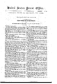
- Fignrel represents a longitudinal section of my ma,- chine for picking cotton
- Figure II is a front v'elevation and Figure III, a section of the tunnel and plan of the" 'bottom platform-plates.”
- This invention is an improvement on the machine forfpicking cotton for which Letters Patent were.
- the invention consists furtherin .the arrangement of a knocking or hammering device applied to one or more of the arms supportingv theabovementioned tube or tunnel, whereby" a succession yof blows or a shaking is communicated throughA said tunnel vto the cote ton-.tree or plant while passing-through thetnnnel.'
- my invention consists .in .apeculiar manner of attaching the plates formingthe bottom pla-tibrmto the lower ends of the, levers, whereby thetree or plant to pass freely under the same, as well as' under the ixles of its wheels.
- levers B B are again bent l inward toward the middle, and have; plates D D attached-meeting near the center,and-.extending for- The inside of j these. levers or arms are connected together by a suit" ward and .backward of' their armsfor' someA distance,
- a'iexible material such as canvas, India rnbbcr,fo r .their equivalent, is attached, extending from one arm to the'otherarm, and forming in connection with the plates D D aclose box,'tu'be, or tnnuehX,thrcuglrwhich the cotton-trees or 'plants can pass.
- This lever F has an upward-projecting arm or nose, G, which is acted upon by points or projections H attached to a revolving: shaft, J.
- This shaftfJ receives motion through the. gearing 2, 3, 2 1,'5, fron1.
- a shaft, K which is' provided .with pinions LI/ (see. fig. II,) on its ends, working into the teeth-wheels L L attached to the front wheelsM of the wagon.
- Thiscylindel discharges'the air into receiver,-S from which apipe, T, leads downward on one side and behind the end oi' the tube ortunnel X formed by the flexible material and Vbottom plates,as above,
- This pipe Tis. closed at the bottom and provided with along slot ,or opening, V, on i its inner side to.- 'ward the center of the machine, and extends nearly ⁇ the whole vheight ofthe tunnel X, through. lwhich the air is discharged and blown across th'ecndot ⁇ said tuu.
- an endless bami, U is arranged, passing over a 'roller, b, placed near' the beginning of the tunnel X, to a roller, h.,
- this-band U runs side by side with a band, Z, passing overroliershaud y., and between which said two bands thecotton is carried upward and falls then into the receiving-box Q placed near the end of the machine.
- Motion is communicated to' these baudsU and Z a wheel, t, attaohed'to the shattO.
- suitable rollers or brushes ' may be arranged io separate the leaves of the plant ii'om 'the cotton.
- the-same may be arranged further back and below j the bottom plates D, and the band U passed-upward above the plates through a suitable-'opening in one of the plates-D.
- the lower ends of the levers or arms B and B', which are turned some distance inward, are arranged with a-eircular' horizontal plate, c, provided -with an npriglrt pinupon which a corresponding plateyp, is
- the forward motion of the machine revolves the shaft J, causing the points or projections Il to act upon the arm or-nose G of tbelever Fin such aman- 1 ner as to produce a succession of blows upon the top .end of the arm E, which are communicated, through the leveli B and plate D resting against the stem of and the cotton 'disconnected from and shaken out of 'the cottou-bolls, and allowed to fall upon the bottom plates D.
- a scraper or brush may be arranged, to brush the cotton blown against the same upon the endless band U.
- The. lever F r'nay be provided with 'a suitable spring for the purposev of increasing thereby the force of tbe blows upon the end of the Varm E, and consequently against the cotton-plant, and this springmay be connected withsaid lever F in such a manner as to be capable of being moved nearer to or further from its. center of modem-whereby the force' of the blow "may, be regulated. 'A
- the inner edges of the plates D maybe provided with a suitable elastic and flexible material acted upon by small springsto-keep the space-between the plates made by the thickness of the stem' of the cotton-plant before 'and behind said plant closed up, to prevent any falling out of the shaken-off cotton.
- the arrangef merit of a close tube or tunnel X capable of separating or opening at the bottom to allow-the cotton-plant to enter and pass through said'tuunel, constructed in the 'mannerand forthe purpose substantially as hereinbefore described.
Landscapes
- Life Sciences & Earth Sciences (AREA)
- Environmental Sciences (AREA)
- Protection Of Plants (AREA)
Description
specification', and
f continu r. COOKE, ornnoontr'n, NEW YORK.
y Letters HitentNo. y101,21*11, vdated March 2Q, 1870.
IMPROVEMENT IN COTTON-PICKERS.
VLP-lie Schedule referred to in these Letters Patent and making of thersaxl'e l. i j
I de hexeby de'clarejfthatl the following is afull and vexact description' of the same, reference being had to the accompanyingv drawingsfnrming partof this to the letters'of reference marked thereon.v v
Fignrel represents a longitudinal section of my ma,- chine for picking cotton;
Figure II is a front v'elevation and Figure III, a section of the tunnel and plan of the" 'bottom platform-plates."
ySimilar letters represent similar Apartsin all the tig'- ures.
This invention is an improvement on the machine forfpicking cotton for which Letters Patent were.
granted t'o me ouuthe 26th dayot' May, 1868, and consists in the arrangement ,of a numberofwbentarms or .levers hingedto the frame of the wagon, extending downward, and `supporting at their lower ends movable plates forming a platform ableiexible material extending from onearm to the other arm, forming. thns,.togeth er. `with .the bottom platesa tube or tunnel through which the cottonf tree oiplantxis made to pass. f
The invention consists furtherin .the arrangement of a knocking or hammering device applied to one or more of the arms supportingv theabovementioned tube or tunnel, whereby" a succession yof blows or a shaking is communicated throughA said tunnel vto the cote ton-.tree or plant while passing-through thetnnnel.'
And further,` my invention consists .in .apeculiar manner of attaching the plates formingthe bottom pla-tibrmto the lower ends of the, levers, whereby thetree or plant to pass freely under the same, as well as' under the ixles of its wheels. l
.These levers are ybent and` Vextend then downward to allow the cotton-trees or plants to pass between i 'the'rn, `turning freely on their center a, and are placed about opposite each other.
The lower ends of these levers B B are again bent l inward toward the middle, and have; plates D D attached-meeting near the center,and-.extending for- The inside of j these. levers or arms are connected together by a suit" ward and .backward of' their armsfor' someA distance,
so that the forward plates overlap '.thoseplaced behind tlie' sanle,'and thus form a continuousplatform of some length. To the inner sides of the levers B B',at the sides and top part, a'iexible material, @,ciiclosey texture, such as canvas, India rnbbcr,fo r .their equivalent, is attached, extending from one arm to the'otherarm, and forming in connection with the plates D D aclose box,'tu'be, or tnnuehX,thrcuglrwhich the cotton-trees or 'plants can pass.`
`To the levers B arms Eareattached, Iextendihg y ward some distance above the frame Apand against `the levers B ,suitable'springs d fastened to the `iframe A and made. t0' ect# y, -f
Above theframe A a hammeror weightedlever, E,
is arranged, turning freely onits center n, andA resting on the top of thea'rmEattached toor. forming apart of the lever B.
This lever F has an upward-projecting arm or nose, G, which is acted upon by points or projections H attached to a revolving: shaft, J.
This shaftfJ receives motion through the. gearing 2, 3, 2 1,'5, fron1.a shaft, K, which is' provided .with pinions LI/ (see. fig. II,) on its ends, working into the teeth-wheels L L attached to the front wheelsM of the wagon.
N, iuV connection with suitablef-piuions .R attached to the ends of said shaft ,0.
, Thiscylindel". discharges'the air into receiver,-S from which apipe, T, leads downward on one side and behind the end oi' the tube ortunnel X formed by the flexible material and Vbottom plates,as above,
described. 4,
This pipe Tis. closed at the bottom and provided with along slot ,or opening, V, on i its inner side to.- 'ward the center of the machine, and extends nearly `the whole vheight ofthe tunnel X, through. lwhich the air is discharged and blown across th'ecndot` said tuu.
nel.- l, ."Iasteadof one ypipe,.as here represented, two or morepipes maybe arranged, some littledistanceone behind the other, vand suitable cocks or valves may,
- be, arrangeddny the pipe lor pipes to regulate o rclose :theescape of air. '1 ,',Opposite to .this pipe 'I on "the other'side `ofthe tube or tunnel'X a-peribrated plate orwire-cloth, W, rs amngcrhextending from the end of the tunnel X to the elevator-box Y.
At the bottom of the tunnel X on the side where tire perforated plate or wire-cloth W is arranged, and
4 close to the top surfaces of the plates D, an endless bami, U, is arranged, passing over a 'roller, b, placed near' the beginning of the tunnel X, to a roller, h.,
-in the bottom of the elevator-box' Y, upwardover a rollen-m, near the top of said box Y, and then down again over a roller, w, near the bottom of said box,
` and hack again to the roller b.
From the roller It tothe roller m this-band U runs side by side with a band, Z, passing overroliershaud y., and between which said two bands thecotton is carried upward and falls then into the receiving-box Q placed near the end of the machine.`
Motion is communicated to' these baudsU and Z a wheel, t, attaohed'to the shattO.
bv means of suitable belts or gearing `connected with Near the roller m, where the cotton is discharged,l suitable rollers or brushes 'may be arranged io separate the leaves of the plant ii'om 'the cotton.
'Instead o f 'placing the roller: b near the front of the tunnel X above 'the plates D, as above described,
' the-same may be arranged further back and below j the bottom plates D, and the band U passed-upward above the plates through a suitable-'opening in one of the plates-D.'
The lower ends of the levers or arms B and B', which are turned some distance inward, are arranged with a-eircular' horizontal plate, c, provided -with an npriglrt pinupon which a corresponding plateyp, is
placed, provided with arms gto which the plates D I .are secrrrely fastened.
' By this ar1angement-these bottom plates D are .capable of turning horizontally around the upright pins in the plates so as to accommodate themselves to any irregularity which may existinthe position of thel cotton-trees or' plants..
"The forward inner ends of theseplates D are rounded oii' or made 'bellfrnouthed, to allow the cotton plants to enter and pass easily between these Plates, (see iig..III.), l
Inl the same manner may the after ends of said plates be rounded to allow the plants to enter freely betweenthe plates, in Vcase the machine should be moved backward. r
The levers-B and B being hinged and turning on their .central bolt 'a will allow the `plates D to move` sideways orto separate, to allow the stern of the cot- The weighted lever or hammer Ff upon the arm E,
l. and the spring d acting against the lever B",.`will cause the 'plates D to layal'ways close against the stem of ,the cottomplats or trees.
The operation of the machine is as follows: IBy means of suitable guides attached to any conveulent part of the camage'or to the arms B B',
(not shown in the drawings, but fully-described in my former above-mentioned patent,) the lower branches of the cotton-plant arel bent or iuoved upward .and
the plant Aguided into the tube or tunnel X between the inner edges of the plates D D.
The forward motion of the machine revolves the shaft J, causing the points or projections Il to act upon the arm or-nose G of tbelever Fin such aman- 1 ner as to produce a succession of blows upon the top .end of the arm E, which are communicated, through the leveli B and plate D resting against the stem of and the cotton 'disconnected from and shaken out of 'the cottou-bolls, and allowed to fall upon the bottom plates D. The cotton thus shaken oli' will he carried aft by the branches of the plants resting upon the plates 1), as well as by the natural current of air through the tunnel X, until met by the strong blast of air coming .from the pipe T, which will blow all the loose cotton thus shaken ofi' against the perforated plate or wire-cloth W, and upon the endless band U, by which latter the cotton is carried up the elevator in` the manner above described, and discharged into the receiving-box Q.
Againstl the surface of the perforated plate or wirecloth W a scraper or brush may be arranged, to brush the cotton blown against the same upon the endless band U.
The. lever F r'nay be provided with 'a suitable spring for the purposev of increasing thereby the force of tbe blows upon the end of the Varm E, and consequently against the cotton-plant, and this springmay be connected withsaid lever F in such a manner as to be capable of being moved nearer to or further from its. center of modem-whereby the force' of the blow "may, be regulated. 'A
The inner edges of the plates D maybe provided with a suitable elastic and flexible material acted upon by small springsto-keep the space-between the plates made by the thickness of the stem' of the cotton-plant before 'and behind said plant closed up, to prevent any falling out of the shaken-off cotton.
.What I claim as my invention, and desireto secure by tters Patent, is 1. he arrangement ofthe bent arms or levers B B', hinged andturniug on their center a, supporting on'their l'lower ends plates D D, and connected by a suitable flexible material C, forming a long close tunnel X, iu the manner and for the purpose substantially as described.
' 2. The arm E attached' to orforming'aypart of the lever B, operated by a'weighted lever or hammer, in
the manner and for the purpose specified.
3. Theweighted lever or hammer F, operatedvby projections or arms H, or their equivalent, andoperating the arms Iwhich support the tube or tunnel X,
iu the manner and for' the purpose essentially as set 4. In a machine for picking cotton, the arrangef merit of a close tube or tunnel X, capable of separating or opening at the bottom to allow-the cotton-plant to enter and pass through said'tuunel, constructed in the 'mannerand forthe purpose substantially as hereinbefore described.
5. '.lhe bottom-plates D attached to the lower ends of the leversvB and B', substantially in theA manner and for the purpose described and set forth.-
6. The arrangement of a tunnel X, Aarranged andI T, the perforated plate W or its equivalent, forming a continuatiorrof said tunnel X at the opposite side f of the air-pipe T, substantially in the manner and'for thepurpose set forth.
y l ROBERT F. COOKE.
Witnesses: HENRY it. Roanne LoUrs S'runu.
Publications (1)
| Publication Number | Publication Date |
|---|---|
| US101231A true US101231A (en) | 1870-03-29 |
Family
ID=2170703
Family Applications (1)
| Application Number | Title | Priority Date | Filing Date |
|---|---|---|---|
| US101231D Expired - Lifetime US101231A (en) | Improvement in cotton-pickers |
Country Status (1)
| Country | Link |
|---|---|
| US (1) | US101231A (en) |
Cited By (1)
| Publication number | Priority date | Publication date | Assignee | Title |
|---|---|---|---|---|
| US2574822A (en) * | 1949-10-24 | 1951-11-13 | Oda M Foster | Dry cotton picker finger |
-
0
- US US101231D patent/US101231A/en not_active Expired - Lifetime
Cited By (1)
| Publication number | Priority date | Publication date | Assignee | Title |
|---|---|---|---|---|
| US2574822A (en) * | 1949-10-24 | 1951-11-13 | Oda M Foster | Dry cotton picker finger |
Similar Documents
| Publication | Publication Date | Title |
|---|---|---|
| US101231A (en) | Improvement in cotton-pickers | |
| US2593625A (en) | Nut gathering machine | |
| US858371A (en) | Cotton-harvester. | |
| US431176A (en) | Fruit-grader | |
| US653136A (en) | Implement for digging and gathering potatoes. | |
| US775456A (en) | Cotton-picking machine. | |
| US503190A (en) | Hop-picking machine | |
| US150578A (en) | Improvement in middlings-purifiers | |
| US1323089A (en) | Cotton-picking machine | |
| US78362A (en) | cooke | |
| US1213529A (en) | Cotton-picker. | |
| US1036357A (en) | Cotton-picker. | |
| US62090A (en) | ttleb | |
| US633216A (en) | Tobacco-planter. | |
| US350059A (en) | William ince | |
| US526209A (en) | Cotton-harvester | |
| US426603A (en) | Hop-picker | |
| US1149458A (en) | Cotton-harvester. | |
| US433302A (en) | Machine for shelling peas | |
| US93946A (en) | Improvement in picker for wool | |
| US1080127A (en) | Cotton-picker. | |
| US259154A (en) | Dust-collector | |
| US1061106A (en) | Concentrator. | |
| US52873A (en) | Improved street-sweeping machine | |
| US636619A (en) | Hair-picking machine. |