US1011012A - Conning-tower for submarine and diving vessels. - Google Patents
Conning-tower for submarine and diving vessels. Download PDFInfo
- Publication number
- US1011012A US1011012A US53251009A US1909532510A US1011012A US 1011012 A US1011012 A US 1011012A US 53251009 A US53251009 A US 53251009A US 1909532510 A US1909532510 A US 1909532510A US 1011012 A US1011012 A US 1011012A
- Authority
- US
- United States
- Prior art keywords
- tower
- conning
- submarine
- abutments
- shaped
- Prior art date
- Legal status (The legal status is an assumption and is not a legal conclusion. Google has not performed a legal analysis and makes no representation as to the accuracy of the status listed.)
- Expired - Lifetime
Links
- 230000009189 diving Effects 0.000 title description 11
- XLYOFNOQVPJJNP-UHFFFAOYSA-N water Substances O XLYOFNOQVPJJNP-UHFFFAOYSA-N 0.000 description 6
- 238000005266 casting Methods 0.000 description 2
- 230000002349 favourable effect Effects 0.000 description 2
- 239000000463 material Substances 0.000 description 2
- 206010011416 Croup infectious Diseases 0.000 description 1
- 238000010276 construction Methods 0.000 description 1
- 230000000694 effects Effects 0.000 description 1
- 238000007689 inspection Methods 0.000 description 1
- 230000003014 reinforcing effect Effects 0.000 description 1
- 230000000717 retained effect Effects 0.000 description 1
- 238000003466 welding Methods 0.000 description 1
Images
Classifications
-
- B—PERFORMING OPERATIONS; TRANSPORTING
- B63—SHIPS OR OTHER WATERBORNE VESSELS; RELATED EQUIPMENT
- B63G—OFFENSIVE OR DEFENSIVE ARRANGEMENTS ON VESSELS; MINE-LAYING; MINE-SWEEPING; SUBMARINES; AIRCRAFT CARRIERS
- B63G8/00—Underwater vessels, e.g. submarines; Equipment specially adapted therefor
- B63G8/38—Arrangement of visual or electronic watch equipment, e.g. of periscopes, of radar
Definitions
- the present invention relates to conning towers for submarine and diving vessels.
- conning towers of this description have been given a perfectly circular cross-section, or else an elliptical one.
- the circular shaped conning tower fulfils the highest claims as regards strength, but on the other hand, produces very great resistance to speed in the water, and must consequently be made comparatively small.
- Towers of elliptical section are very favor able as regards utilization of space, but lay very slight claim to resistance against outside water pressure and it is very diificult to compute their strength.
- the object of the present invention is to produce a conning tower for submarine and diving vessels, which, on the one hand, gives little speed resistance and permits of good use of space, and, on the other hand, possesses such a cross-section, that the strain on the tower from outside water pressure may be computed exactly enough, so that the tower may possess the greatest safety against undue changes in shape with the use of least material.
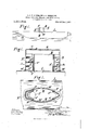
- Figure 1 shows in elevation a diving vessel provided with conning tower; Fig. 2, the conning tower with part of the vessel in a vertical, longitudinal section and in larger scale than Fig. 1, and Fig. 3, a section on line 33 of Fig. 2.
- the conning tower consists principally of two side walls M, bent to circular arches,
- the tower further consists of a roof 0 provided with an entrancehatch 0
- the roof is also firmly and tightly riveted to the walls M, N and N of the tower.
- the entire tower is riveted to the hull L of the boat through the medium of a ring 991.
- the braces 91?, n have only to prevent any possiblebuckling of the abutments N, N from outside water pressure and to retain the straight walls in the tangential position to the side walls M, this being the most favorable position, for taking up the arch-thrust.
- both abutments N, N might be made V-shaped, or both U- shaped.
- the wall might be divided into two longitudinal halves and the halves, which may be pressed, may be connected together by rivets.
- the rigid connection between the several parts of the tower might of course also be obtained by welding.
- the entire tower with the cover 0 and the reinforcing ribs may be formed as an integral casting (steel-casting or bronzecasting).
- the basic form of the tower as shown in Fig. 3 must be retained, as the side walls M, must be bent as circular arches, on the one hand, and on the other hand the abutments N, N being V-shaped or U-shaped and having straight sides, must run tangentially to the sides M.
- the side walls M of the above described conning tower may be built on the principle of a cone instead of a circular cylinder. Without deviation from the object of the invention, the arching of the side-walls M may furthermore be slightly out of a true circular section, as the then appearing bending-moments will be very small as compared with the considerably larger stresses ob tained by computing the walls against buckling.
- a conning tower for submarine or diving vessels the side-walls of which are curved as circular arcs, and terminate in straight abutments, continuing from the arcs in directions substantially tangential thereto.
- a conning tower for submarine or diving vessels the side-walls of which are curved as circular arcs, and terminate in straight abutments, continuing from the arcs in directions substantially tangential thereto; said abutments being respectively V-shaped and U-shaped, in cross-section, and forming the bow and stern parts of the tower.
- a conning tower for submarine or diving vessels the side-walls of which are curved as circular arcs, and terminate in straight abutments, continuing from the arcs in directions substantially tangential thereto; said abutments being respectively V-shaped and U-shaped, in cross-section, and forming the bow and stern parts of the tower, and a plurality of horizontal braces being provided for said abutments to prevent buckling.
Landscapes
- Engineering & Computer Science (AREA)
- Radar, Positioning & Navigation (AREA)
- Mechanical Engineering (AREA)
- Aviation & Aerospace Engineering (AREA)
- Wind Motors (AREA)
Description
G. J. K. BBHRMANN & E. HURLBRINK. GONNING TOWER FOB. SUBMARINE AND DIVING VESSELS.
APPLICATION FILED DEC. 10, 1909. 1,01 1,01 2.
I Patented Dec.5,1911,
GEGRG JOACHIM KARL BEI-IRMANN AND ERNST HURLBBINK, OF
KIEL, GERMANY,
ASSIGNORS TO FRIED. KRUPP AKTIENGESELLSCHAFT, GERMANIAWERFT, OF KIEL- GAARIDEN, GERMANY.
CONNING-TOWER FOR SUBMARINE AND DIVING VESSELS.
Application filed December 10, 1909.
T 0 all whom it may concern;
Be it known that we Gnone JOACHIM KARL BEHRMANN and ERNST HURLBRINK,
both subjects of the Emperor of Germany,
and residing at Kiel, Germany, have invented certain new and useful Improvements in Conning-Towers for Submarine and Diving Vessels, of which the following is a specification.
The present invention relates to conning towers for submarine and diving vessels. Heretofore conning towers of this description have been given a perfectly circular cross-section, or else an elliptical one. The circular shaped conning tower fulfils the highest claims as regards strength, but on the other hand, produces very great resistance to speed in the water, and must consequently be made comparatively small. Towers of elliptical section are very favor able as regards utilization of space, but lay very slight claim to resistance against outside water pressure and it is very diificult to compute their strength. In order, notwithstanding, to obtain enough safety when using elliptical tower construction, resource had to be taken either to allow to a certain extent deformations of the tower; or else to making the side walls thereof strong enough to be able to resist, under all conditions, the outside water pressure. In the latter case, the weight of the vessel was naturally unfavorably increased.
The object of the present invention, is to produce a conning tower for submarine and diving vessels, which, on the one hand, gives little speed resistance and permits of good use of space, and, on the other hand, possesses such a cross-section, that the strain on the tower from outside water pressure may be computed exactly enough, so that the tower may possess the greatest safety against undue changes in shape with the use of least material.
One embodiment of our invention is represented in the drawing, wherein Figure 1 shows in elevation a diving vessel provided with conning tower; Fig. 2, the conning tower with part of the vessel in a vertical, longitudinal section and in larger scale than Fig. 1, and Fig. 3, a section on line 33 of Fig. 2.
The conning tower consists principally of two side walls M, bent to circular arches,
Specification of Letters Patent.
Patented Dec. 5, 1911. Serial No. 532,510.
and two abutments N, N bent V-shaped and U -shaped, respectively, and firmly and tightly connected to the side walls M, by means of angles a and straps n all riveted together, the plates at the joints running tangentially to the side walls M. The tower further consists of a roof 0 provided with an entrancehatch 0 The roof is also firmly and tightly riveted to the walls M, N and N of the tower. The entire tower is riveted to the hull L of the boat through the medium of a ring 991. of L-shaped cross-section and two angle-plates n arranged within the abutments N and N The ring m is greatly enlarged at those places where it lies against the abutments N and N On their inside the abutments N and N are provided with strong angular braces n and a which eX- tend horizontally and which are of L-shaped crosssection and I-shaped cross-section respectively. When a diving boat provided with such a conning tower dives the eX- terior pressure of the water tends to press the side-walls M toward each other. However as the side walls are suspended in an arch-like manner between their abutments N and N their arch-thrust is transmitted to the straight parts of the tangentially running abutments N and N The straight sides of the abutments will then be strained as evenly loaded beams, raised on edge, and rigidly supported at both ends (at the towerroof 0, and the hull L). They will therefore be subjected to an easily computed stress, and, having a sufliciently high crosssection in horizontal direction, will transfer the arch-thrust completely to the firm towerroof 0, and the hull L. The braces 91?, n have only to prevent any possiblebuckling of the abutments N, N from outside water pressure and to retain the straight walls in the tangential position to the side walls M, this being the most favorable position, for taking up the arch-thrust.
As the kind of the stress on the different parts of the conning tower describedv in the foregoing is completely capable of inspection and as the dimension of the parts can thus be exactly calculated, a collapse of the tower due to the exterior water-pressure can be avoided with certainty without unnecessary expenditure of material. This is not the case with the conning towers having elliptical cross-section. Furthermore the conning tower shown in the drawings permits of almost the same utilization of space as a conning tower of elliptical cross-section.
Instead of making one abutment V-shaped and the other U-shaped, both abutments N, N might be made V-shaped, or both U- shaped. And furthermore instead of making the wall of four parts, as described in the foregoing, the wall might be divided into two longitudinal halves and the halves, which may be pressed, may be connected together by rivets. The rigid connection between the several parts of the tower might of course also be obtained by welding. Finally, the entire tower with the cover 0 and the reinforcing ribs may be formed as an integral casting (steel-casting or bronzecasting). However, in all instances, to obtain the desired effect the basic form of the tower as shown in Fig. 3 must be retained, as the side walls M, must be bent as circular arches, on the one hand, and on the other hand the abutments N, N being V-shaped or U-shaped and having straight sides, must run tangentially to the sides M.
The side walls M of the above described conning tower may be built on the principle of a cone instead of a circular cylinder. Without deviation from the object of the invention, the arching of the side-walls M may furthermore be slightly out of a true circular section, as the then appearing bending-moments will be very small as compared with the considerably larger stresses ob tained by computing the walls against buckling.
Having thus described our invention, what we now claim as new and desire to secure by Letters Patent, is
1. A conning tower for submarine or diving vessels, the side-walls of which are curved as circular arcs, and terminate in straight abutments, continuing from the arcs in directions substantially tangential thereto.
2. A conning tower for submarine or diving vessels, the side-walls of which are curved as circular arcs, and terminate in straight abutments, continuing from the arcs in directions substantially tangential thereto; said abutments being respectively V-shaped and U-shaped, in cross-section, and forming the bow and stern parts of the tower.
3. A conning tower for submarine or diving vessels, the side-walls of which are curved as circular arcs, and terminate in straight abutments, continuing from the arcs in directions substantially tangential thereto; said abutments being respectively V-shaped and U-shaped, in cross-section, and forming the bow and stern parts of the tower, and a plurality of horizontal braces being provided for said abutments to prevent buckling.
The foregoing specification signed at Kiel, Germany, this 24th day of November, 1909.
GEORG JOACHIM KARL BEHRMANN. ERNST HURLBRINK.
In presence of- JULIUS Ronni, KURT BUNDE.
Copies of this patent may be obtained for five cents each, by addressing the Commissioner of Patents, Washington, D. G.
Priority Applications (1)
| Application Number | Priority Date | Filing Date | Title |
|---|---|---|---|
| US53251009A US1011012A (en) | 1909-12-10 | 1909-12-10 | Conning-tower for submarine and diving vessels. |
Applications Claiming Priority (1)
| Application Number | Priority Date | Filing Date | Title |
|---|---|---|---|
| US53251009A US1011012A (en) | 1909-12-10 | 1909-12-10 | Conning-tower for submarine and diving vessels. |
Publications (1)
| Publication Number | Publication Date |
|---|---|
| US1011012A true US1011012A (en) | 1911-12-05 |
Family
ID=3079321
Family Applications (1)
| Application Number | Title | Priority Date | Filing Date |
|---|---|---|---|
| US53251009A Expired - Lifetime US1011012A (en) | 1909-12-10 | 1909-12-10 | Conning-tower for submarine and diving vessels. |
Country Status (1)
| Country | Link |
|---|---|
| US (1) | US1011012A (en) |
-
1909
- 1909-12-10 US US53251009A patent/US1011012A/en not_active Expired - Lifetime
Similar Documents
| Publication | Publication Date | Title |
|---|---|---|
| JP6636462B2 (en) | Pressure-resistant bulkhead for aircraft fuselage | |
| US1011012A (en) | Conning-tower for submarine and diving vessels. | |
| US1980998A (en) | Vessel | |
| RU2587742C1 (en) | Between-compartment bulkhead of underwater technical facility | |
| RU2652688C2 (en) | Submarine bulkhead | |
| EE01389U1 (en) | A hinge module for connecting catamaran-type vessel's platform and hull | |
| US1492981A (en) | Ship | |
| US255599A (en) | William coppin | |
| US2965060A (en) | Structure of submarine boats | |
| US811886A (en) | Construction of submarine boats. | |
| RU217088U1 (en) | Light inter-compartment bulkhead of an underwater technical facility | |
| US1229004A (en) | Construction of submarine vessels. | |
| US106620A (en) | Improvement in paddle-wheels | |
| RU2678144C2 (en) | Between-compartment bulkhead of underwater technical facility | |
| US3585954A (en) | Method of moving sidewall of watertight floating box | |
| US1009230A (en) | Hull of navigable vessels. | |
| US1266356A (en) | Ship's light. | |
| US689821A (en) | Hull construction. | |
| US1165535A (en) | Submarine vessel. | |
| US1319480A (en) | Ship construction | |
| USRE47E (en) | Improvement in the manner of lining vessels constructed of sheet-iron | |
| US878752A (en) | Twin-screw submarine boat. | |
| US975699A (en) | Ship or vessel. | |
| US835800A (en) | Jury-rudder. | |
| US1303046A (en) | Seamless metallic boat colsrstrtjctiojff |