US10103561B2 - Power supply system - Google Patents
Power supply system Download PDFInfo
- Publication number
- US10103561B2 US10103561B2 US14/849,642 US201514849642A US10103561B2 US 10103561 B2 US10103561 B2 US 10103561B2 US 201514849642 A US201514849642 A US 201514849642A US 10103561 B2 US10103561 B2 US 10103561B2
- Authority
- US
- United States
- Prior art keywords
- battery
- switching element
- arm
- electric circuit
- time
- Prior art date
- Legal status (The legal status is an assumption and is not a legal conclusion. Google has not performed a legal analysis and makes no representation as to the accuracy of the status listed.)
- Active, expires
Links
Images
Classifications
-
- H02J7/0054—
-
- B—PERFORMING OPERATIONS; TRANSPORTING
- B60—VEHICLES IN GENERAL
- B60L—PROPULSION OF ELECTRICALLY-PROPELLED VEHICLES; SUPPLYING ELECTRIC POWER FOR AUXILIARY EQUIPMENT OF ELECTRICALLY-PROPELLED VEHICLES; ELECTRODYNAMIC BRAKE SYSTEMS FOR VEHICLES IN GENERAL; MAGNETIC SUSPENSION OR LEVITATION FOR VEHICLES; MONITORING OPERATING VARIABLES OF ELECTRICALLY-PROPELLED VEHICLES; ELECTRIC SAFETY DEVICES FOR ELECTRICALLY-PROPELLED VEHICLES
- B60L3/00—Electric devices on electrically-propelled vehicles for safety purposes; Monitoring operating variables, e.g. speed, deceleration or energy consumption
- B60L3/0023—Detecting, eliminating, remedying or compensating for drive train abnormalities, e.g. failures within the drive train
- B60L3/003—Detecting, eliminating, remedying or compensating for drive train abnormalities, e.g. failures within the drive train relating to inverters
-
- B60L11/1868—
-
- B—PERFORMING OPERATIONS; TRANSPORTING
- B60—VEHICLES IN GENERAL
- B60L—PROPULSION OF ELECTRICALLY-PROPELLED VEHICLES; SUPPLYING ELECTRIC POWER FOR AUXILIARY EQUIPMENT OF ELECTRICALLY-PROPELLED VEHICLES; ELECTRODYNAMIC BRAKE SYSTEMS FOR VEHICLES IN GENERAL; MAGNETIC SUSPENSION OR LEVITATION FOR VEHICLES; MONITORING OPERATING VARIABLES OF ELECTRICALLY-PROPELLED VEHICLES; ELECTRIC SAFETY DEVICES FOR ELECTRICALLY-PROPELLED VEHICLES
- B60L3/00—Electric devices on electrically-propelled vehicles for safety purposes; Monitoring operating variables, e.g. speed, deceleration or energy consumption
- B60L3/0092—Electric devices on electrically-propelled vehicles for safety purposes; Monitoring operating variables, e.g. speed, deceleration or energy consumption with use of redundant elements for safety purposes
-
- B—PERFORMING OPERATIONS; TRANSPORTING
- B60—VEHICLES IN GENERAL
- B60L—PROPULSION OF ELECTRICALLY-PROPELLED VEHICLES; SUPPLYING ELECTRIC POWER FOR AUXILIARY EQUIPMENT OF ELECTRICALLY-PROPELLED VEHICLES; ELECTRODYNAMIC BRAKE SYSTEMS FOR VEHICLES IN GENERAL; MAGNETIC SUSPENSION OR LEVITATION FOR VEHICLES; MONITORING OPERATING VARIABLES OF ELECTRICALLY-PROPELLED VEHICLES; ELECTRIC SAFETY DEVICES FOR ELECTRICALLY-PROPELLED VEHICLES
- B60L58/00—Methods or circuit arrangements for monitoring or controlling batteries or fuel cells, specially adapted for electric vehicles
- B60L58/10—Methods or circuit arrangements for monitoring or controlling batteries or fuel cells, specially adapted for electric vehicles for monitoring or controlling batteries
- B60L58/18—Methods or circuit arrangements for monitoring or controlling batteries or fuel cells, specially adapted for electric vehicles for monitoring or controlling batteries of two or more battery modules
- B60L58/20—Methods or circuit arrangements for monitoring or controlling batteries or fuel cells, specially adapted for electric vehicles for monitoring or controlling batteries of two or more battery modules having different nominal voltages
-
- H—ELECTRICITY
- H02—GENERATION; CONVERSION OR DISTRIBUTION OF ELECTRIC POWER
- H02J—CIRCUIT ARRANGEMENTS OR SYSTEMS FOR SUPPLYING OR DISTRIBUTING ELECTRIC POWER; SYSTEMS FOR STORING ELECTRIC ENERGY
- H02J7/00—Circuit arrangements for charging or depolarising batteries or for supplying loads from batteries
- H02J7/34—Parallel operation in networks using both storage and other DC sources, e.g. providing buffering
- H02J7/342—The other DC source being a battery actively interacting with the first one, i.e. battery to battery charging
-
- H—ELECTRICITY
- H02—GENERATION; CONVERSION OR DISTRIBUTION OF ELECTRIC POWER
- H02M—APPARATUS FOR CONVERSION BETWEEN AC AND AC, BETWEEN AC AND DC, OR BETWEEN DC AND DC, AND FOR USE WITH MAINS OR SIMILAR POWER SUPPLY SYSTEMS; CONVERSION OF DC OR AC INPUT POWER INTO SURGE OUTPUT POWER; CONTROL OR REGULATION THEREOF
- H02M1/00—Details of apparatus for conversion
-
- H—ELECTRICITY
- H02—GENERATION; CONVERSION OR DISTRIBUTION OF ELECTRIC POWER
- H02M—APPARATUS FOR CONVERSION BETWEEN AC AND AC, BETWEEN AC AND DC, OR BETWEEN DC AND DC, AND FOR USE WITH MAINS OR SIMILAR POWER SUPPLY SYSTEMS; CONVERSION OF DC OR AC INPUT POWER INTO SURGE OUTPUT POWER; CONTROL OR REGULATION THEREOF
- H02M3/00—Conversion of DC power input into DC power output
- H02M3/02—Conversion of DC power input into DC power output without intermediate conversion into AC
- H02M3/04—Conversion of DC power input into DC power output without intermediate conversion into AC by static converters
- H02M3/10—Conversion of DC power input into DC power output without intermediate conversion into AC by static converters using discharge tubes with control electrode or semiconductor devices with control electrode
- H02M3/145—Conversion of DC power input into DC power output without intermediate conversion into AC by static converters using discharge tubes with control electrode or semiconductor devices with control electrode using devices of a triode or transistor type requiring continuous application of a control signal
- H02M3/155—Conversion of DC power input into DC power output without intermediate conversion into AC by static converters using discharge tubes with control electrode or semiconductor devices with control electrode using devices of a triode or transistor type requiring continuous application of a control signal using semiconductor devices only
- H02M3/156—Conversion of DC power input into DC power output without intermediate conversion into AC by static converters using discharge tubes with control electrode or semiconductor devices with control electrode using devices of a triode or transistor type requiring continuous application of a control signal using semiconductor devices only with automatic control of output voltage or current, e.g. switching regulators
- H02M3/158—Conversion of DC power input into DC power output without intermediate conversion into AC by static converters using discharge tubes with control electrode or semiconductor devices with control electrode using devices of a triode or transistor type requiring continuous application of a control signal using semiconductor devices only with automatic control of output voltage or current, e.g. switching regulators including plural semiconductor devices as final control devices for a single load
-
- B—PERFORMING OPERATIONS; TRANSPORTING
- B60—VEHICLES IN GENERAL
- B60L—PROPULSION OF ELECTRICALLY-PROPELLED VEHICLES; SUPPLYING ELECTRIC POWER FOR AUXILIARY EQUIPMENT OF ELECTRICALLY-PROPELLED VEHICLES; ELECTRODYNAMIC BRAKE SYSTEMS FOR VEHICLES IN GENERAL; MAGNETIC SUSPENSION OR LEVITATION FOR VEHICLES; MONITORING OPERATING VARIABLES OF ELECTRICALLY-PROPELLED VEHICLES; ELECTRIC SAFETY DEVICES FOR ELECTRICALLY-PROPELLED VEHICLES
- B60L2210/00—Converter types
- B60L2210/10—DC to DC converters
-
- B—PERFORMING OPERATIONS; TRANSPORTING
- B60—VEHICLES IN GENERAL
- B60L—PROPULSION OF ELECTRICALLY-PROPELLED VEHICLES; SUPPLYING ELECTRIC POWER FOR AUXILIARY EQUIPMENT OF ELECTRICALLY-PROPELLED VEHICLES; ELECTRODYNAMIC BRAKE SYSTEMS FOR VEHICLES IN GENERAL; MAGNETIC SUSPENSION OR LEVITATION FOR VEHICLES; MONITORING OPERATING VARIABLES OF ELECTRICALLY-PROPELLED VEHICLES; ELECTRIC SAFETY DEVICES FOR ELECTRICALLY-PROPELLED VEHICLES
- B60L2240/00—Control parameters of input or output; Target parameters
- B60L2240/40—Drive Train control parameters
- B60L2240/54—Drive Train control parameters related to batteries
- B60L2240/547—Voltage
-
- H02J2007/0059—
-
- H02J2105/37—
-
- H—ELECTRICITY
- H02—GENERATION; CONVERSION OR DISTRIBUTION OF ELECTRIC POWER
- H02J—CIRCUIT ARRANGEMENTS OR SYSTEMS FOR SUPPLYING OR DISTRIBUTING ELECTRIC POWER; SYSTEMS FOR STORING ELECTRIC ENERGY
- H02J2207/00—Indexing scheme relating to details of circuit arrangements for charging or depolarising batteries or for supplying loads from batteries
- H02J2207/20—Charging or discharging characterised by the power electronics converter
-
- Y—GENERAL TAGGING OF NEW TECHNOLOGICAL DEVELOPMENTS; GENERAL TAGGING OF CROSS-SECTIONAL TECHNOLOGIES SPANNING OVER SEVERAL SECTIONS OF THE IPC; TECHNICAL SUBJECTS COVERED BY FORMER USPC CROSS-REFERENCE ART COLLECTIONS [XRACs] AND DIGESTS
- Y02—TECHNOLOGIES OR APPLICATIONS FOR MITIGATION OR ADAPTATION AGAINST CLIMATE CHANGE
- Y02T—CLIMATE CHANGE MITIGATION TECHNOLOGIES RELATED TO TRANSPORTATION
- Y02T10/00—Road transport of goods or passengers
- Y02T10/60—Other road transportation technologies with climate change mitigation effect
- Y02T10/70—Energy storage systems for electromobility, e.g. batteries
-
- Y—GENERAL TAGGING OF NEW TECHNOLOGICAL DEVELOPMENTS; GENERAL TAGGING OF CROSS-SECTIONAL TECHNOLOGIES SPANNING OVER SEVERAL SECTIONS OF THE IPC; TECHNICAL SUBJECTS COVERED BY FORMER USPC CROSS-REFERENCE ART COLLECTIONS [XRACs] AND DIGESTS
- Y02—TECHNOLOGIES OR APPLICATIONS FOR MITIGATION OR ADAPTATION AGAINST CLIMATE CHANGE
- Y02T—CLIMATE CHANGE MITIGATION TECHNOLOGIES RELATED TO TRANSPORTATION
- Y02T10/00—Road transport of goods or passengers
- Y02T10/60—Other road transportation technologies with climate change mitigation effect
- Y02T10/72—Electric energy management in electromobility
Definitions
- the present invention relates to a power supply system in which voltage conversion is performed bidirectionally between either or both of two batteries and an output electric circuit.
- a hybrid vehicle and an electric vehicle that employ a rotary electric machine as a driving source are provided with a power supply system including a battery, which is a direct-current power supply, and a voltage transducer for stepping up a battery voltage and stepping down a regenerative electric power caused by the rotary electric machine.
- a voltage transducer there has been known a buck-boost converter as illustrated in FIG. 28 .
- the buck-boost converter steps up/down a voltage by ON/OFF operations of two switching elements S 1 , S 2 .
- JP 2012-070514 A describes a voltage transducer including four switching elements S 1 to S 4 and connected to two batteries B 1 , B 2 , as illustrated in FIG. 29 .
- the voltage transducer can step up/down a voltage by ON/OFF operations of the four switching elements S 1 to S 4 , and can switch the two batteries between series connection and parallel connection by changing ON-OFF patterns of the switching elements.
- a voltage is stepped up/down by an ON/OFF operation of a switching element S 2 in synchronization with an ON/OFF operation of a switching element S 1 . Accordingly, when either one of the switching elements S 1 , S 2 has an ON fault and is turned on continuously, a voltage cannot be stepped up/down in the above manner.
- the present invention provides a power supply system that can perform voltage conversion even at the time of an ON fault of a switching element.
- a power supply system related an aspect of the present invention includes a first battery, a second battery, an output electric circuit, a first switching element, a second switching element, and a third switching element.
- the output electric circuit is configured to perform voltage conversion bidirectionally with either one or both of the first battery and the second battery.
- the output electric circuit includes a first electric circuit and a second electric circuit.
- the second electric circuit has a potential lower than a potential of the first electric circuit.
- the first switching element, the second switching element, and the third switching element are provided in series with each other from the first electric circuit toward the second electric circuit.
- the first battery is provided in parallel with the second switching element.
- the second battery is provided in parallel with a series connection between the second switching element and the third switching element.
- the power supply system may further includes a first system main relay, a second system main relay and a controlling portion.
- the first system main relay may be configured such that the first battery is connected in parallel with the second switching element via the first system main relay.
- the second system main relay may be configured such that the second battery is connected in parallel with the series connection between the second switching element and the third switching element via the second system main relay.
- the controlling portion may be configured to perform ON-OFF controls on the first switching element, the second switching element, the third switching element, the first system main relay and the second system main relay.
- the controlling portion may be configured to, at a time of an ON fault of the first switching element, turn off the second system main relay and execute a first failsafe mode by performing ON-OFF controls on the second switching element and the third switching element.
- the controlling portion may be configured to step up a voltage of the first battery in the first failsafe mode.
- the power supply system may further includes a first system main relay, a second system main relay and a controlling portion.
- the first system main relay may be configured such that the first battery is connected in parallel with the second switching element via the first system main relay.
- the second system main relay may be configured such that the second battery is connected in parallel with the series connection between the second switching element and the third switching element via the second system main relay.
- the controlling portion may be configured to perform ON-OFF controls on the first switching element, the second switching element, the third switching element, the first system main relay and the second system main relay.
- the controlling portion may be configured to, at a time of an ON fault of the second switching element, turn off the first system main relay and execute a second failsafe mode by performing ON-OFF controls on the first switching element and the third switching element.
- the controlling portion may be configured to step up a voltage of the second battery in the second failsafe mode.
- the second battery may have a voltage higher than a voltage of the first battery.
- the first battery and the second battery may be placed in a loop circuit via the third switching element.
- the controlling portion may be configured to control connection or disconnection between the first battery and the second battery by performing an ON-OFF control on the third switching element.
- the controlling portion may be configured to control a charging current by adjusting a conduction resistance of the third switching element, when an electric power is supplied to the first battery from the second battery by connecting the first battery to the second battery.
- a power supply system related to the other aspect of the present invention includes a first battery, a second battery, an output electric circuit, a first switching element, a second switching element, and a third switching element.
- the output electric circuit is configured to perform voltage conversion bidirectionally with either one or both of the first battery and the second battery.
- the output electric circuit includes a first electric circuit and a second electric circuit.
- the second electric circuit has a potential lower than a potential of the first electric circuit.
- the first switching element, the second switching element, and the third switching element are provided in series with each other from the first electric circuit toward the second electric circuit.
- the first battery is provided in parallel with the third switching element.
- the second battery is provided in parallel with a series connection between the second switching element and the third switching element.
- the power supply system may further includes a first system main relay, a second system main relay and a controlling portion.
- the first system main relay is configured such that the first battery is connected in parallel with the third switching element via the first system main relay.
- the second system main relay is configured such that the second battery is connected in parallel with the series connection between the second switching element and the third switching element via the second system main relay.
- the controlling portion may be configured to perform ON-OFF controls on the first switching element, the second switching element, the third switching element, the first system main relay and the second system main relay.
- the controlling portion may be configured to, at a time of an ON fault of the first switching element, turn off the second system main relay and execute a first failsafe mode by performing ON-OFF controls on the second switching element and the third switching element.
- the controlling portion may be configured to step up a voltage of the first battery in the first failsafe mode.
- the power supply system may further includes a first system main relay, a second system main relay and a controlling portion.
- the first system main relay imay be configured such that the first battery is connected in parallel with the third switching element via the first system main relay.
- the second system main relay may be configured such that the second battery is connected in parallel with the series connection between the second switching element and the third switching element via the second system main relay.
- the controlling portion may be configured to perform ON-OFF controls on the first switching element, the second switching element, the third switching element, the first system main relay and the second system main relay.
- the controlling portion may be configured to, at a time of an ON fault of the third switching element, turn off the first system main relay and execute a second failsafe mode by performing ON-OFF controls on the first switching element and the second switching element.
- the controlling portion may be configured to step up a voltage of the second battery in the second failsafe mode.
- the second battery may have a voltage higher than a voltage of the first battery.
- the first battery and the second battery may be placed in a loop circuit via the second switching element.
- the controlling portion may be configured to control connection or disconnection between the first battery and the second battery by controlling ON-OFF of the second switching element.
- the controlling portion may be configured to control a charging current by adjusting a conduction resistance of the second switching element, when an electric power is supplied to the first battery from the second battery by connecting the first battery to the second battery.
- FIG. 1 is a configuration diagram of an electric system of a vehicle which electric system includes a power supply system according to the present embodiment
- FIG. 2 is a configuration diagram of the power supply system according to the present embodiment
- FIG. 3 is a view of a first buck-boost circuit extracted from the power supply system according to the present embodiment
- FIG. 4 is a view of a second buck-boost circuit extracted from the power supply system according to the present embodiment
- FIG. 5 is a view exemplifying an operation at the time of step-up storage in a parallel step-up/step-down mode in a normal time, among step-up/step-down operations using the power supply system according to the present embodiment;
- FIG. 6 is a view exemplifying an operation at the time of step-up discharge in the parallel step-up/step-down mode in a normal time, among the step-up/step-down operations using the power supply system according to the present embodiment;
- FIG. 7 is a view exemplifying an operation at the time of step-down storage in the parallel step-up/step-down mode in a normal time, among the step-up/step-down operations using the power supply system according to the present embodiment;
- FIG. 8 is a view exemplifying an operation at the time of step-down discharge in the parallel step-up/step-down mode in a normal time, among the step-up/step-down operations using the power supply system according to the present embodiment;
- FIG. 9 is a view exemplifying an operation at the time of step-up storage and step-down discharge in a step-up/step-down mode in an ON fault of a switching element S 1 , among the step-up/step-down operations using the power supply system according to the present embodiment;
- FIG. 10 is a view exemplifying an operation at the time of step-up discharge and step-down storage in the step-up/step-down mode in the ON fault of the switching element S 1 , among the step-up/step-down operations using the power supply system according to the present embodiment;
- FIG. 11 is a view exemplifying an operation at the time of step-up storage and step-down discharge in a step-up/step-down mode in an ON fault of a switching element S 2 , among the step-up/step-down operations using the power supply system according to the present embodiment;
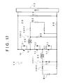
- FIG. 12 is a view exemplifying an operation at the time of step-up discharge and step-down storage in the step-up/step-down mode in the ON fault of the switching element S 2 , among the step-up/step-down operations using the power supply system according to the present embodiment;
- FIG. 13 is a view exemplifying an operation in a B 1 single direct connection mode using the power supply system according to the present embodiment
- FIG. 14 is a view exemplifying an operation in a B 2 single direct connection mode using the power supply system according to the present embodiment
- FIG. 15 is a view to describe an inter-battery current
- FIG. 16 is a view to describe a half-ON control by a switching element S 3 ;
- FIG. 17 is a configuration diagram of a power supply system according to another embodiment.
- FIG. 18 is a view of a first buck-boost circuit extracted from the power supply system according to the another embodiment
- FIG. 19 is a view of a second buck-boost circuit extracted from the power supply system according to the another embodiment.
- FIG. 20 is a view exemplifying an operation at the time of step-up storage and step-down discharge in a parallel step-up/step-down mode in a normal time, among step-up/step-down operations using the power supply system according to the another embodiment;
- FIG. 21 is a view exemplifying an operation at the time of step-up discharge and step-down storage in the parallel step-up/step-down mode in a normal time, among the step-up/step-down operations using the power supply system according to the another embodiment;
- FIG. 22 is a view exemplifying an operation at the time of step-up storage and step-down discharge in a step-up/step-down mode in an ON fault of a switching element S 1 , among the step-up/step-down operations using the power supply system according to the another embodiment;
- FIG. 23 is a view exemplifying an operation at the time of step-up discharge and step-down storage in the step-up/step-down mode in the ON fault of the switching element S 1 , among the step-up/step-down operations using the power supply system according to the another embodiment;
- FIG. 24 is a view exemplifying an operation at the time of step-up storage and step-down discharge in a step-up/step-down mode in an ON fault of a switching element S 3 , among the step-up/step-down operations using the power supply system according to the another embodiment;
- FIG. 25 is a view exemplifying an operation at the time of step-up discharge and step-down storage in the step-up/step-down mode in the ON fault of the switching element S 3 , among the step-up/step-down operations using the power supply system according to the another embodiment;
- FIG. 26 is a view exemplifying an operation in a B 1 single direct connection mode using the power supply system according to the another embodiment
- FIG. 27 is a view exemplifying an operation in a B 2 single direct connection mode using the power supply system according to the another embodiment
- FIG. 28 is a view exemplifying a conventional buck-boost converter.
- FIG. 29 is a view exemplifying a conventional voltage transducer.
- FIG. 1 exemplifies a configuration diagram of an electric system of a vehicle which electric system includes a power supply system 10 according to the present embodiment. Note that an alternate long and short dash line in FIG. 1 indicates a signal line.
- the power supply system 10 is an electric power supply for a rotary electric machine 12 serving as a drive source of a vehicle.
- a vehicle in which the power supply system 10 is provided is constituted by a hybrid vehicle or an electric vehicle, for example.
- the power supply system 10 includes a first battery B 1 , a second battery B 2 , a voltage transducer 14 , an inverter 16 , system main relays SMR 1 , SMR 2 , and a controlling portion 18 .
- the first battery B 1 and the second battery B 2 are connected to the voltage transducer 14 .
- the voltage transducer 14 steps up direct voltages VL 1 , VL 2 from the first battery B 1 and the second battery B 2 , and outputs them to the inverter 16 .
- the inverter 16 is constituted by a three-phase inverter, and is connected to the rotary electric machine 12 .
- the inverter 16 converts a direct-current power stepped up by the voltage transducer 14 into a three-phase alternating-current power, and outputs it to the rotary electric machine 12 .
- the rotary electric machine 12 is rotationally driven.
- a driving force of the rotary electric machine 12 is transmitted to driving wheels (not shown).
- regenerative braking is performed by the rotary electric machine 12 .
- a regenerative electric power obtained at this time is subjected to AC/DC conversion performed by the inverter 16 so as to be converted into a direct-current power, and the direct-current power is then stepped down by the voltage transducer 14 so as to be supplied to the first battery B 1 and the second battery B 2 .
- the controlling portion 18 controls step-up/step-down (voltage conversion) of a direct voltage by controlling ON/OFF of switching elements S 1 , S 2 , S 3 of the voltage transducer 14 . Further, the controlling portion 18 controls DC/AC conversion and AC/DC conversion by controlling ON/OFF of a switching element (not shown) of the inverter 16 . Through the controls on the voltage transducer 14 and the inverter 16 , the controlling portion 18 controls driving of the rotary electric machine 12 .
- the first battery B 1 and the second battery B 2 are direct-current power supplies each constituted by a secondary battery, and are each constituted by a lithium-ion storage battery or a nickel metal hydride storage battery, for example. Further, at least one of the first battery B 1 and the second battery B 2 may be a storage element such as an electric double layer capacitor, instead of the secondary battery. Further, as will be described later, respective battery voltages of the first battery B 1 and the second battery B 2 are managed so that a voltage VL 2 of the second battery B 2 is higher than a voltage VL 1 of the first battery B 1 .
- the first battery B 1 is connected in parallel with the switching element S 2 of the voltage transducer 14 via the system main relay SMR 1 . Further, the second battery B 2 is connected in parallel with the switching elements S 2 and S 3 of the voltage transducer 14 via the system main relay SMR 2 .
- the system main relays SMR 1 , SMR 2 each include three types of relays. That is, positive relays 20 A, 20 B are connected to respective positive sides of the batteries B 1 , B 2 , and negative relays 22 A, 22 B are connected to respective negative sides thereof. Further, as a configuration to prevent rush current at the time when the first battery B 1 and the second battery B 2 are connected to a circuit, precharge relays 24 A, 24 B are connected in parallel with the negative relays 22 A, 22 B. Resistors 26 A, 26 B are connected in series with the precharge relays 24 A, 24 B, respectively.
- the voltage transducer 14 performs ON/OFF operations on the switching elements S 1 , S 2 , S 3 , so as to perform voltage conversion bidirectionally from the first battery B 1 and the second battery B 2 to output electric circuits 28 , 30 (and the rotary electric machine 12 as their destinations) and vice versa.
- FIG. 2 exemplifies an extracted view of the voltage transducer 14 and its peripherals.
- the output electric circuits 28 , 30 constituting an output of the voltage transducer 14 are connected to a load such as the rotary electric machine 12 .
- the output electric circuits 28 , 30 are constituted by a high-voltage electric circuit 28 , which is a first electric circuit, and a reference electric circuit 30 , which is a second electric circuit with a potential lower than that of the high-voltage electric circuit 28 .
- a smoothing capacitor 31 is provided in parallel with the load between the high-voltage electric circuit 28 and the reference electric circuit 30 .
- the voltage transducer 14 is provided with the first, second, third switching elements S 1 , S 2 , S 3 in series from the high-voltage electric circuit 28 toward the reference electric circuit 30 .
- the switching elements S 1 , S 2 , S 3 are each constituted by, for example, an IGBT (an insulated gate bipolar transistor).
- the switching elements S 1 , S 2 , S 3 are each provided so that a forward current direction between its collector and its emitter is the same as a direction from a high-voltage side to a low-voltage side, that is, a direction from the high-voltage electric circuit 28 to the reference electric circuit 30 .
- diodes D 1 , D 2 , D 3 are connected in reverse-parallel to the switching elements S 1 , S 2 , S 3 , respectively. That is, each of the diodes D 1 , D 2 , D 3 is provided so as to flow a current from the reference electric circuit 30 to the high-voltage electric circuit 28 .
- a set of a switching element and a diode connected in reverse-parallel thereto is referred to as an arm.
- a set of the switching element S 1 and the diode D 1 , a set of the switching element S 2 and the diode D 2 , and a set of the switching element S 3 and the diode D 3 constitute respective arms.
- the voltage transducer 14 is provided with a first reactor 34 connected in series with the first battery B 1 , and a first capacitor 36 connected in parallel with the first battery B 1 .
- the voltage transducer 14 is provided with a second reactor 40 connected in series with the second battery B 2 , and a second capacitor 42 connected in parallel with the second battery B 2 .
- the voltage transducer 14 , the first battery B 1 , and the second battery B 2 are connected in the following manner. That is, a positive electrode of the first battery B 1 is connected to a first node N 1 between the switching elements S 1 and S 2 of the voltage transducer 14 via the first reactor 34 , and a negative electrode of the first battery B 1 is connected to a second node N 2 between the switching elements S 2 and S 3 . A positive electrode of the second battery B 2 is connected to the first node N 1 via the second reactor 40 , and a negative electrode of the second battery B 2 is connected to the reference electric circuit 30 .
- the controlling portion 18 performs various operation controls of the vehicle, including voltage conversion to the voltage transducer 14 and the inverter 16 , as will be described later.
- the controlling portion 18 may be constituted by a computer such that a CPU 44 , a storage portion 46 , and a device/sensor interface 48 are connected to each other via an internal bus 50 .
- the controlling portion 18 receives signals from various sensors via the device/sensor interface 48 . More specifically, as signals related to the first battery B 1 and the second battery B 2 , the controlling portion 18 receives respective detection values from battery voltage sensors 52 A, 52 B for measuring voltage values VL 1 , VL 2 of respective batteries, battery current sensors 54 A, 54 B for measuring current values IB 1 , IB 2 of respective batteries, and an output voltage sensor 56 for measuring output voltage values VH in the output electric circuits 28 , 30 .
- the controlling portion 18 receives detection signals of a rotation angle and a three-phase alternating current of the rotary electric machine 12 from a resolver 58 and current sensors 60 A, 60 B, as signals related to the rotary electric machine 12 . Further, the controlling portion 18 receives detection signals of stepping-in amounts of respective pedals from an accelerator pedal stepping-in amount sensor and a brake pedal stepping-in amount sensor (not shown) as other vehicle information.
- controlling portion 18 supplies control signals to the switching elements S 1 , S 2 , S 3 of the voltage transducer 14 and the switching element of the inverter 16 via the device/sensor interface 48 .
- the CPU 44 of the controlling portion 18 executes various control programs stored in the storage portion 46 , and performs arithmetic processing on detection signals received from various sensors, so as to perform ON/OFF controls on the switching elements S 1 , S 2 , S 3 of the voltage transducer 14 and an ON/OFF control on the switching element of the inverter 16 .
- ON/OFF controls on the switching elements of the voltage transducer 14 and the inverter 16 driving of the rotary electric machine 12 is controlled.
- controlling portion 18 performs ON/OFF (contact closing/contact opening) controls on the system main relays SMR 1 , SMR 2 .
- ON/OFF controls on the system main relays SMR 1 , SMR 2 according to ON-fault states of the switching elements S 1 , S 2 , S 3 .
- a step-up/step-down operation can be performed at the time of an ON fault of the switching elements S 1 , S 2 , S 3 .
- the voltage transducer 14 according to the present embodiment has an expanded function of a conventional buck-boost converter illustrated in FIG. 28 .
- the following description describes an operation of the voltage transducer 14 according to the present embodiment based on an operation of the conventional buck-boost converter.
- the operation of the voltage transducer 14 according to the present embodiment is obtained such that respective operations of a first buck-boost circuit CNV 1 on a first-battery-B 1 side and a second buck-boost circuit CNV 2 on a second-battery-B 2 side are superimposed on top of each other by a so-called principle of superposition (superposition theorem).
- a buck-boost circuit of the voltage transducer 14 according to the present embodiment based on two buck-boost circuits CNV 1 , CNV 2 , separately, for convenience.
- the lower arm indicates an arm forming a loop circuit including a battery and a reactor.
- the upper arm indicates an arm that connects a battery, a reactor, and a load (a high-voltage electric circuit 28 ).
- Switching elements of the upper arm and the lower arm are turned on/off complementarily. That is, when the switching element of the lower arm is turned on, the switching element of the upper arm is turned off. Conversely, when the switching element of the upper arm is turned on, the switching element of the lower arm is turned off.
- a step-up/step-down operation by the conventional buck-boost converter is well known, but is described here briefly.
- an electric power is transferred to an output side, an electric energy from a battery is first stored in a reactor by lower-arm ON as a step-up process. Then, the electric power thus stored in the reactor is added to an electric power of the battery by lower-arm OFF, and then sent to the output side.
- an electric energy from the output side is stored in the reactor by upper-arm ON as a step-down process. Further, the electric power thus stored in the reactor is sent to the battery by upper-arm OFF.
- FIG. 3 is a view of the first buck-boost circuit CNV 1 extracted from the voltage transducer 14 according to the present embodiment. From the viewpoint of the aforementioned functions of the upper arm and the lower arm, in the first buck-boost circuit CNV 1 illustrated in FIG. 3 , an arm (an S 1 -arm) including the switching element Si and an arm (an S 3 -arm) including the switching element S 3 serve as upper arms, and an arm (an S 2 -arm) including the switching element S 2 serves as a lower arm.
- FIG. 4 is an extracted view of the second buck-boost circuit CNV 2 on a second-battery-B 2 side.
- the S 1 -arm serves as an upper arm
- the S 2 -arm and the S 3 -arm serve as lower arms.
- the S 1 -arm, the S 2 -arm, and the S 3 -arm when viewed from each of the buck-boost circuits CNV 1 , CNV 2 have roles as described in Table 1 below.
- the voltage transducer 14 includes the S 3 -arm that functions as the upper arm for the first buck-boost circuit CNV 1 and also functions as the lower arm for the second buck-boost circuit CNV 2 , in addition to the S 1 -arm as the upper arm and the S 2 -arm as the lower arm.
- the first buck-boost circuit CNV 1 includes the S 3 -arm as another upper arm, and therefore, even if the S 1 -arm serving as the upper arm has an ON fault, a step-up/step-down operation is performable by using the S 2 -arm (the lower arm) and the S 3 -arm (the upper arm).
- the second buck-boost circuit CNV 2 includes the S 3 -arm as another lower arm, and therefore, even if the S 2 -arm serving as the lower arm has an ON fault, a step-up/step-down operation is performable by using the S 1 -arm (the upper arm) and the S 3 -arm (the lower arm).
- the voltage transducer according to the present embodiment is configured such that a step-up/step-down operation is performable even at the time of an ON fault of a switching element. Note that a step-up/step-down operation by the S 1 -arm and the S 2 -arm is performable with the S 3 -arm being turned on continuously.
- FIGS. 5, 6 illustrate an operation at the time when voltages of the first battery B 1 and the second battery B 2 are stepped up by the voltage transducer 14 .
- FIG. 5 illustrates currents to cause an electric energy to be stored in the first reactor 34 and the second reactor 40 from the first battery B 1 and the second battery B 2 .
- FIG. 6 illustrates an operation at the time when the electric energy thus stored is discharged to the load.
- lower-arm OFF is achieved, and upper-arm ON is achieved accordingly. That is, in the first buck-boost circuit CNV 1 , the S 1 -arm and the S 3 -arm are turned on, and the S 2 -arm is turned off.
- the second buck-boost circuit CNV 2 the S 1 -arm is turned on, and the S 2 -arm and the S 3 -arm are turned off.
- the controlling portion 18 finds a logical sum thereof, and achieves S 1 -arm ON, S 2 -arm OFF, and S 3 -arm ON.
- FIGS. 7, 8 illustrate an operation at the time when an output-side energy from the rotary electric machine 12 is stepped down.
- FIG. 7 exemplifies an operation at the time when the output-side energy is stored in the first reactor 34 and the second reactor 40 .
- upper-arm ON is achieved, and lower-arm OFF is achieved accordingly. That is, similarly to FIG. 6 , in the first buck-boost circuit CNV 1 , the S 1 -arm and the S 3 -arm are turned on, and the S 2 -arm is turned off.
- the second buck-boost circuit CNV 2 the S 1 -arm is turned on, and the S 2 -arm and the S 3 -arm are turned off.
- the controlling portion 18 finds a logical sum thereof, and achieves S 1 -arm ON, S 2 -arm OFF, and S 3 -arm ON.
- FIG. 8 illustrates an operation at the time when electric energies stored in the first reactor 34 and the second reactor 40 in FIG. 7 are discharged to the first battery B 1 and the second battery B 2 .
- upper-arm OFF is achieved, and lower-arm ON is achieved accordingly. That is, similarly to FIG. 5 , in the first buck-boost circuit CNV 1 , the S 1 -arm and the S 3 -arm are turned off, and the S 2 -arm is turned on.
- the second buck-boost circuit CNV 2 the S 1 -arm is turned off, and the S 2 -arm and the S 3 -arm are turned on.
- the controlling portion 18 finds a logical sum thereof, and achieves S 1 -arm OFF, S 2 -arm ON, and S 3 -arm ON.
- the switching element S 3 in a parallel step-up/step-down operation in a normal time, the switching element S 3 is in a continuously ON state, so that the batteries B 1 , B 2 are connected in parallel with each other, and the S 1 -arm and the S 2 -arm are controlled to be ON/OFF complementarily.
- the first buck-boost circuit CNV 1 and the second buck-boost circuit CNV 2 are controlled so as to become generally equipotential. For example, when there are predetermined voltage request and current request to the load, a voltage control to step up an output voltage to a requested voltage is performed in the second buck-boost circuit CNV 2 . In the meantime, in the first buck-boost circuit CNV 1 , a current control to output a current that compensates a difference between a requested current and an output current of the second buck-boost circuit CNV 2 is performed.
- FIGS. 9, 10 An operation of the voltage transducer 14 at the time when the switching element S 1 has an ON fault (short-circuit fault) is described with reference to FIGS. 9, 10 .
- the arms perform the same operations at the time of step-up storage and at the time of step-down discharge, and also at the time of step-up discharge and at the time of step-down storage.
- operations at the time of step-up storage and at the time of step-down discharge are described collectively, and operations at the time of step-up discharge and at the time of step-down storage are also described collectively.
- the controlling portion 18 performs the following switch control as a first failsafe mode. That is, the controlling portion 18 turns off the system main relay SMR 2 (contact opening) so as to separate the second battery B 2 from the voltage transducer 14 , thereby stopping an operation of the second buck-boost circuit CNV 2 . Then, a step-up/step-down operation is performed by the first buck-boost circuit CNV 1 .
- FIG. 9 illustrates an operation at the time of step-up storage and at the time of step-down discharge, when the switching element S 1 has an ON fault.
- an upper arm is turned off and a lower arm is turned on. That is, in the first buck-boost circuit CNV 1 (the S 1 -arm has an ON fault), the S 2 -arm is turned on, and the S 3 -arm is turned off.
- the second buck-boost circuit CNV 2 stops its operation, an operation of the first buck-boost circuit CNV 1 is just reflected as a logical sum.
- FIG. 10 illustrates an operation at the time of step-up discharge and at the time of step-down storage, when the switching element S 1 has an ON fault.
- an upper arm is turned on and a lower arm is turned off. That is, in the first buck-boost circuit CNV 1 (the S 1 -arm has an ON fault), the S 2 -arm is turned off, and the S 3 -arm is turned on.
- FIGS. 11, 12 An operation of the voltage transducer 14 at the time when the switching element S 2 has an ON fault is described with reference to FIGS. 11, 12 .
- a lower arm viewed from the first buck-boost circuit CNV 1 , has an ON fault, so that a step-up/step-down operation using the circuit CNV 1 cannot be performed.
- the controlling portion 18 performs the following switch control as a second failsafe mode. That is, the controlling portion 18 turns off the system main relay SMR 1 so as to separate the first battery B 1 from the voltage transducer 14 , thereby stopping an operation of the first buck-boost circuit CNV 1 . Further, a step-up/step-down operation is performed by the second buck-boost circuit CNV 2 .
- FIG. 11 illustrates an operation at the time of step-up storage and at the time of step-down discharge, when the switching element S 2 has an ON fault.
- an upper arm is turned off and a lower arm is turned on. That is, in the second buck-boost circuit CNV 2 , the S 1 -arm is turned off (the S 2 -arm has an ON fault), and the S 3 -arm is turned on.
- the first buck-boost circuit CNV 1 stops its operation, an operation of the second buck-boost circuit CNV 2 is just reflected as a logical sum.
- FIG. 12 illustrates an operation at the time of step-up discharge and at the time of step-down storage, when the switching element S 2 has an ON fault.
- an upper arm is turned on and a lower arm is turned off. That is, in the second buck-boost circuit CNV 2 , the S 1 -arm is turned on (the S 2 -arm has an ON fault), and the S 3 -arm is turned off.
- the S 3 -arm is controlled to be ON/OFF instead of the arm thus having an ON fault.
- one of two buck-boost circuits CNV 1 , CNV 2 is usable, which makes it possible to perform a step-up/step-down operation at the time of an ON fault of a switching element, which cannot be performed in the related art.
- An operation at the time of an ON fault of the switching element S 3 is the same as the parallel step-up/step-down operation ( FIGS. 5 to 8 ) in a normal time in which the switching element S 3 is turned on continuously. That is, fields for S 3 in an upper table in FIGS. 5 to 8 are replaced with “S 3 : ON fault,” so that an operation at the time of an ON fault of the switching element S 3 is obtained. In view of this, illustration and detailed descriptions thereof are omitted herein.
- FIG. 13 illustrates an operation at the time when the first battery B 1 singularly supplies an electric power to the load without performing a step-up/step-down operation.
- the first buck-boost circuit CNV 1 and the second buck-boost circuit CNV 2 may not become equipotential, unlike the step-up/stepdown operation.
- an inter-battery current (current loop) via the S 3 -arm might occur between the first battery B 1 and the second battery B 2 depending on a potential difference.
- the controlling portion 18 turns off the system main relay SMR 2 so as to separate the second battery B 2 from the voltage transducer 14 .
- the S 1 -arm In the B 1 single direct connection mode, only the operation of the first buck-boost circuit CNV 1 at the time of step-up discharge in the parallel step-up/step-down operation in a normal time as illustrated in FIG. 6 is picked out and fixed. That is, in the B 1 single direct connection mode, the S 1 -arm is fixed to an ON state, the S 2 -arm is fixed to an OFF state, and the S 3 -arm is fixed to an ON state. Note that, in this mode, the S 1 -arm and the S 3 -arm are fixed to an ON state. Accordingly, even in a case where the S 1 -arm and the S 3 -arm have an ON fault, this mode can be used.
- FIG. 14 illustrates an operation at the time when the second battery B 2 singularly supplies an electric power to the load, instead of FIG. 13 .
- the controlling portion 18 turns off the system main relay SMR 1 so as to separate the first battery B 1 from the voltage transducer 14 .
- the S 1 -arm In the B 2 single direct connection mode, only the operation of the second buck-boost circuit CNV 2 at the time of step-up discharge in the parallel step-up/step-down operation in a normal time is picked out and fixed. That is, in the B 2 single direct connection mode, the S 1 -arm is fixed to an ON state, the S 2 -arm is fixed to an OFF state, and the S 3 -arm is fixed to an OFF state. Note that, in this mode, the S 1 -arm is fixed to an ON state. Accordingly, even in a case where the S 1 -arm has an ON fault, this mode can be used.
- an inter-battery current (current loop) via the S 3 -arm might occur between the first battery B 1 and the second battery B 2 .
- FIG. 15 in a case where the system main relays SMR 1 and SMR 2 are ON states and the first battery voltage VL 1 has a higher voltage than the second battery voltage VL 2 , even if the switching elements S 1 to S 3 are turned off, a current loop is formed between the first battery B 1 and the second battery B 2 via the diode D 3 of the S 3 -arm.
- Such an operation state can occur at the time when the power supply system starts, that is, after the system main relays SMR 1 , SMR 2 are turned on but before a step-up/step-down operation starts.
- a second battery voltage VL 2 is set higher than a first battery voltage VL 1 , thereby preventing the occurrence of the inter-battery current via the diode D 3 of the S 3 -arm. If the switching element S 3 is turned off in such a voltage relationship, it is possible to prevent the occurrence of the inter-battery current. That is, by controlling ON/OFF of the switching element S 3 , connection/disconnection between the first battery B 1 and the second battery B 2 can be controlled.
- the switching element S 3 is operated so as to charge the first battery B 1 from the second battery B 2 .
- a collector-emitter conduction resistance of the switching element S 3 is adjusted, so as to control a charging current.
- FIG. 16 exemplifies a control at the time of charging the first battery B 1 .
- the controlling portion 18 decreases a conduction ratio of the switching element S 3 as compared with a normal ON operation, thereby reducing a charging current amount to be supplied to the first battery B 1 via the switching element S 3 .
- the controlling portion 18 adjusts a gate voltage V G of the switching element S 3 , so that a collector-emitter voltage V CE of the switching element S 3 is set so as to be higher than that of a normal ON operation (half-ON).
- the collector-emitter voltage V CE is adjusted so that a sum of the first battery voltage VL 1 and the collector-emitter voltage V CE of the switching element S 3 is slightly lower than the second battery voltage VL 2 .
- the controlling portion 18 may perform a current control of controlling the gate voltage V G of the switching element S 3 so that a first battery current IB 1 detected by a battery current sensor 54 A falls within a predetermined threshold.
- FIG. 17 exemplifies a voltage transducer 14 according to another embodiment.
- the voltage transducer 14 is different from the voltage transducer 14 of FIG. 2 in a configuration of a first buck-boost circuit CNV 1 .
- a first battery B 1 is connected in parallel with a switching element S 3 , instead of a switching element S 2 . More specifically, the first battery B 1 is connected to a second node N 2 between the switching elements S 2 and S 3 , and a reference electric circuit 30 .
- the voltage transducer 14 is configured such that a first reactor 34 is connected in series with the first battery B 1 , and a first capacitor 36 is connected in parallel with the first battery B 1 . Further, a system main relay SMR 1 is provided between the voltage transducer 14 and the first battery B 1 .
- the other configuration is the same as the voltage transducer 14 illustrated in FIG. 2 .
- FIG. 18 is an extracted view of a first buck-boost circuit CNV 1 .
- an S 1 -arm and an S 2 -arm serve as upper arms
- an S 3 -arm serves as a lower arm.
- FIG. 19 is an extracted view of a second buck-boost circuit CNV 2 .
- the S 1 -arm serves as an upper arm
- the S 2 -arm and the S 3 -arm serve as lower arms.
- the first buck-boost circuit CNV 1 includes the upper arms redundantly
- the second buck-boost circuit CNV 2 includes the lower arms redundantly.
- FIG. 20 illustrates an operation at the time of step-up storage and at the time of step-down discharge in a parallel step-up/step-down mode of the first battery B 1 and the second battery B 2 .
- an upper arm is turned off and a lower arm is turned on. That is, in the first buck-boost circuit CNV 1 , the S 1 -arm and the S 2 -arm are turned off, and the S 3 -arm is turned on.
- the second buck-boost circuit CNV 2 the S 1 -arm is turned off, and the S 2 -arm and the S 3 -arm are turned on.
- the controlling portion 18 finds a logical sum thereof, and achieves S 1 -arm OFF, S 2 -arm ON, and S 3 -arm ON.
- FIG. 21 illustrates an operation at the time of step-up discharge and at the time of step-down storage similarly in the parallel step-up/step-down mode.
- an upper arm is turned on and a lower arm is turned off. That is, in the first buck-boost circuit CNV 1 , the S 1 -arm and the S 2 -arm are turned on, and the S 3 -arm is turned off.
- the second buck-boost circuit CNV 2 the S 1 -arm is turned on, and the S 2 -arm and the S 3 -arm are turned off.
- the controlling portion 18 finds a logical sum thereof, and achieves S 1 -arm ON, S 2 -arm ON, and S 3 -arm OFF.
- the switching element S 2 is in a continuously ON state, and the S 1 -arm and the S 3 -arm are controlled to be ON/OFF complementarily.
- FIG. 22 An operation of the voltage transducer 14 at the time when the switching element S 1 has an ON fault (short-circuit fault) is described with reference to FIGS. 22, 23 .
- an ON fault of the switching element S 1 an ON fault of the S 1 -arm
- an upper arm viewed from the second buck-boost circuit CNV 2
- the controlling portion 18 performs the following switch control as a first failsafe mode.
- the controlling portion 18 turns off the system main relay SMR 2 (contact opening) so as to separate the second battery B 2 from the voltage transducer 14 , thereby stopping an operation of the second buck-boost circuit CNV 2 . Further, a step-up/step-down operation is performed by the first buck-boost circuit CNV 1 .
- FIG. 22 illustrates an operation at the time of step-up storage and at the time of step-down discharge, when the switching element S 1 has an ON fault.
- an upper arm is turned off and a lower arm is turned on. That is, in the first buck-boost circuit CNV 1 (the S 1 -arm has an ON fault), the S 2 -arm is turned off and the S 3 -arm is turned on.
- the second buck-boost circuit CNV 2 stops its operation, an operation of the first buck-boost circuit CNV 1 is just reflected as a logical sum.
- FIG. 23 illustrates an operation at the time of step-up discharge and at the time of step-down storage, when the switching element S 1 has an ON fault.
- an upper arm is turned on and a lower arm is turned off. That is, in the first buck-boost circuit CNV 1 (the S 1 -arm has an ON fault), the S 2 -arm is turned on and the S 3 -arm is turned off.
- An operation at the time of an ON fault of the switching element S 2 is the same as the parallel step-up/step-down operation ( FIGS. 20, 21 ) in a normal time in which the switching element S 2 is turned on continuously. That is, fields for S 2 in an upper table in FIGS. 20, 21 are replaced with “S 2 : ON fault,” so that an operation at the time of an ON fault of the switching element S 2 is obtained. In view of this, illustration and detailed descriptions thereof are omitted herein.
- FIGS. 24, 25 An operation of the voltage transducer 14 at the time when the switching element S 3 has an ON fault is described with reference to FIGS. 24, 25 .
- a lower arm viewed from the first buck-boost circuit CNV 1 , has an ON fault, so that a step-up/step-down operation using the circuit CNV 1 cannot be performed.
- the controlling portion 18 performs the following switch control as a second failsafe mode. That is, the controlling portion 18 turns off the system main relay SMR 1 so as to separate the first battery B 1 from the voltage transducer 14 , thereby stopping an operation of the first buck-boost circuit CNV 1 . Further, a step-up/step-down operation is performed by the second buck-boost circuit CNV 2 .
- FIG. 24 illustrates an operation at the time of step-up storage and at the time of step-down discharge, when the switching element S 3 has an ON fault.
- an upper arm is turned off and a lower arm is turned on. That is, in the second buck-boost circuit CNV 2 , the S 1 -arm is turned off, and the S 2 -arm is turned on (the S 3 -arm has an ON fault).
- the first buck-boost circuit CNV 1 stops its operation, an operation of the second buck-boost circuit CNV 2 is just reflected as a logical sum.
- FIG. 25 illustrates an operation at the time of step-up discharge and at the time of step-down storage, when the switching element S 3 has an ON fault.
- an upper arm is turned on and a lower arm is turned off. That is, in the second buck-boost circuit CNV 2 , the S 1 -arm is turned on, and the S 2 -arm is turned off (the S 3 -arm has an ON fault).
- the S 2 -arm is controlled to be ON/OFF instead of the arm thus having an ON fault.
- at least one of two buck-boost circuits CNV 1 , CNV 2 is usable, which makes it possible to perform a step-up/step-down operation at the time of an ON fault of a switching element, which cannot be performed in the related art.
- FIG. 26 illustrates an operation at the time when the first battery B 1 singularly supplies an electric power to a load without performing a step-up/step-down operation.
- the first buck-boost circuit CNV 1 and the second buck-boost circuit CNV 2 may not become equipotential, unlike the step-up/stepdown operation.
- an inter-battery current (current loop) via the S 2 -arm might occur between the first battery B 1 and the second battery B 2 depending on a potential difference.
- the controlling portion 18 turns off the system main relay SMR 2 so as to separate the second battery B 2 from the voltage transducer 14 .
- the B 1 single direct connection mode only the operation of the first buck-boost circuit CNV 1 at the time of step-up discharge in the parallel step-up/step-down operation in a normal time as illustrated in FIG. 21 is picked out and fixed. That is, in the B 1 single direct connection mode, the S 1 -arm and the S 2 -arm are fixed to an ON state, and the S 3 -arm is fixed to an OFF state. Note that, in this mode, the S 1 -arm and the S 2 -arm are fixed to an ON state. Accordingly, even in a case where the S 1 -arm and the S 2 -arm have an ON fault, this mode can be used.
- FIG. 27 illustrates an operation at the time when the second battery B 2 singularly supplies an electric power to the load, instead of FIG. 26 .
- the controlling portion 18 turns off the system main relay SMR 1 so as to separate the first battery B 1 from the voltage transducer 14 .
- an inter-battery current (current loop) via the S 2 -arm might occur between the first battery B 1 and the second battery B 2 .
- a second battery voltage VL 2 is set higher than a first battery voltage VL 1 , thereby preventing the occurrence of the inter-battery current via a diode D 2 of the S 2 -arm. If the switching element S 2 is turned off in such a voltage relationship, it is possible to prevent the occurrence of the inter-battery current. That is, by controlling ON/OFF of the switching element S 2 , connection/disconnection between the first battery B 1 and the second battery B 2 can be controlled.
- a half-ON control is performed on the switching element S 2 as mentioned earlier, so that a collector-emitter conduction resistance of the switching element S 2 is adjusted, so as to control a charging current.
Landscapes
- Engineering & Computer Science (AREA)
- Power Engineering (AREA)
- Life Sciences & Earth Sciences (AREA)
- Sustainable Development (AREA)
- Sustainable Energy (AREA)
- Transportation (AREA)
- Mechanical Engineering (AREA)
- Dc-Dc Converters (AREA)
- Charge And Discharge Circuits For Batteries Or The Like (AREA)
- Electric Propulsion And Braking For Vehicles (AREA)
Abstract
A power supply system comprises a first battery, a second battery, an output electric circuit, a first switching element, a second switching element, and a third switching element. The output electric circuit includes a first electric circuit and a second electric circuit. The second electric circuit has a potential lower than a potential of the first electric circuit. The first, second and third switching elements are provided in series with each other from the first electric circuit toward the second electric circuit. The first battery is provided in parallel with the second switching element. The second battery is provided in parallel with a series connection between the second switching element and the third switching element.
Description
The disclosure of Japanese Patent Application No. 2014-185458 filed on Sep. 11, 2014 including the specification, drawings and abstract is incorporated herein by reference in its entirety.
1. Field of the Invention
The present invention relates to a power supply system in which voltage conversion is performed bidirectionally between either or both of two batteries and an output electric circuit.
2. Description of Related Art
A hybrid vehicle and an electric vehicle that employ a rotary electric machine as a driving source are provided with a power supply system including a battery, which is a direct-current power supply, and a voltage transducer for stepping up a battery voltage and stepping down a regenerative electric power caused by the rotary electric machine. As the voltage transducer, there has been known a buck-boost converter as illustrated in FIG. 28 . The buck-boost converter steps up/down a voltage by ON/OFF operations of two switching elements S1, S2.
Further, as a voltage transducer having an expanded function of the buck-boost converter, Japanese Patent Application Publication No. 2012-070514 (JP 2012-070514 A), for example, describes a voltage transducer including four switching elements S1 to S4 and connected to two batteries B1, B2, as illustrated in FIG. 29 . The voltage transducer can step up/down a voltage by ON/OFF operations of the four switching elements S1 to S4, and can switch the two batteries between series connection and parallel connection by changing ON-OFF patterns of the switching elements.
In the meantime, in a conventional voltage transducer, it is difficult to perform voltage conversion at the time of an ON fault (short-circuit fault) of a switching element. For example, in a buck-boost converter illustrated in FIG. 28 , as generally known, a voltage is stepped up/down by an ON/OFF operation of a switching element S2 in synchronization with an ON/OFF operation of a switching element S1. Accordingly, when either one of the switching elements S1, S2 has an ON fault and is turned on continuously, a voltage cannot be stepped up/down in the above manner.
In the voltage transducer illustrated in FIG. 29 , even if either of the switching elements S1 to S4 has an ON fault, a voltage can be stepped up/down theoretically by use of either of the batteries B1, B2. However, in this case, another problem is caused such that the stepping up/down of a voltage should be stopped from the viewpoint of safety. For example, at the time of an ON fault of the switching element S3, the battery B1 is connected in series with the battery B2, so that an output voltage is a voltage sum of the battery B1 and the battery B2. This voltage might exceed withstanding voltages of system main relays SMR1, SMR2, and the like, so the voltage transducer illustrated in FIG. 29 eventually cannot help but stop the stepping up/down of a voltage at the time of an ON fault of the switching element.
The present invention provides a power supply system that can perform voltage conversion even at the time of an ON fault of a switching element.
A power supply system related an aspect of the present invention includes a first battery, a second battery, an output electric circuit, a first switching element, a second switching element, and a third switching element. The output electric circuit is configured to perform voltage conversion bidirectionally with either one or both of the first battery and the second battery. The output electric circuit includes a first electric circuit and a second electric circuit. The second electric circuit has a potential lower than a potential of the first electric circuit. The first switching element, the second switching element, and the third switching element are provided in series with each other from the first electric circuit toward the second electric circuit. The first battery is provided in parallel with the second switching element. The second battery is provided in parallel with a series connection between the second switching element and the third switching element.
According to the power supply system of the present invention, it is possible to perform voltage conversion even at the time of an ON fault of a switching element
The power supply system may further includes a first system main relay, a second system main relay and a controlling portion. The first system main relay may be configured such that the first battery is connected in parallel with the second switching element via the first system main relay. The second system main relay may be configured such that the second battery is connected in parallel with the series connection between the second switching element and the third switching element via the second system main relay. The controlling portion may be configured to perform ON-OFF controls on the first switching element, the second switching element, the third switching element, the first system main relay and the second system main relay. The controlling portion may be configured to, at a time of an ON fault of the first switching element, turn off the second system main relay and execute a first failsafe mode by performing ON-OFF controls on the second switching element and the third switching element. The controlling portion may be configured to step up a voltage of the first battery in the first failsafe mode.
The power supply system may further includes a first system main relay, a second system main relay and a controlling portion. The first system main relay may be configured such that the first battery is connected in parallel with the second switching element via the first system main relay. The second system main relay may be configured such that the second battery is connected in parallel with the series connection between the second switching element and the third switching element via the second system main relay. The controlling portion may be configured to perform ON-OFF controls on the first switching element, the second switching element, the third switching element, the first system main relay and the second system main relay. The controlling portion may be configured to, at a time of an ON fault of the second switching element, turn off the first system main relay and execute a second failsafe mode by performing ON-OFF controls on the first switching element and the third switching element. The controlling portion may be configured to step up a voltage of the second battery in the second failsafe mode.
Furthermore, the second battery may have a voltage higher than a voltage of the first battery. The first battery and the second battery may be placed in a loop circuit via the third switching element. The controlling portion may be configured to control connection or disconnection between the first battery and the second battery by performing an ON-OFF control on the third switching element.
The controlling portion may be configured to control a charging current by adjusting a conduction resistance of the third switching element, when an electric power is supplied to the first battery from the second battery by connecting the first battery to the second battery.
A power supply system related to the other aspect of the present invention includes a first battery, a second battery, an output electric circuit, a first switching element, a second switching element, and a third switching element. The output electric circuit is configured to perform voltage conversion bidirectionally with either one or both of the first battery and the second battery. The output electric circuit includes a first electric circuit and a second electric circuit. The second electric circuit has a potential lower than a potential of the first electric circuit. The first switching element, the second switching element, and the third switching element are provided in series with each other from the first electric circuit toward the second electric circuit. The first battery is provided in parallel with the third switching element. The second battery is provided in parallel with a series connection between the second switching element and the third switching element.
The power supply system may further includes a first system main relay, a second system main relay and a controlling portion. The first system main relay is configured such that the first battery is connected in parallel with the third switching element via the first system main relay. The second system main relay is configured such that the second battery is connected in parallel with the series connection between the second switching element and the third switching element via the second system main relay. The controlling portion may be configured to perform ON-OFF controls on the first switching element, the second switching element, the third switching element, the first system main relay and the second system main relay. The controlling portion may be configured to, at a time of an ON fault of the first switching element, turn off the second system main relay and execute a first failsafe mode by performing ON-OFF controls on the second switching element and the third switching element. The controlling portion may be configured to step up a voltage of the first battery in the first failsafe mode.
The power supply system may further includes a first system main relay, a second system main relay and a controlling portion. The first system main relay imay be configured such that the first battery is connected in parallel with the third switching element via the first system main relay. The second system main relay may be configured such that the second battery is connected in parallel with the series connection between the second switching element and the third switching element via the second system main relay. The controlling portion may be configured to perform ON-OFF controls on the first switching element, the second switching element, the third switching element, the first system main relay and the second system main relay. The controlling portion may be configured to, at a time of an ON fault of the third switching element, turn off the first system main relay and execute a second failsafe mode by performing ON-OFF controls on the first switching element and the second switching element. The controlling portion may be configured to step up a voltage of the second battery in the second failsafe mode.
Furthermore, the second battery may have a voltage higher than a voltage of the first battery. The first battery and the second battery may be placed in a loop circuit via the second switching element. The controlling portion may be configured to control connection or disconnection between the first battery and the second battery by controlling ON-OFF of the second switching element.
The controlling portion may be configured to control a charging current by adjusting a conduction resistance of the second switching element, when an electric power is supplied to the first battery from the second battery by connecting the first battery to the second battery.
Features, advantages, and technical and industrial significance of exemplary embodiments of the invention will be described below with reference to the accompanying drawings, in which like numerals denote like elements, and wherein:
With reference to the drawings, the following describes an embodiment of the present invention. FIG. 1 exemplifies a configuration diagram of an electric system of a vehicle which electric system includes a power supply system 10 according to the present embodiment. Note that an alternate long and short dash line in FIG. 1 indicates a signal line.
The power supply system 10 is an electric power supply for a rotary electric machine 12 serving as a drive source of a vehicle. A vehicle in which the power supply system 10 is provided is constituted by a hybrid vehicle or an electric vehicle, for example. The power supply system 10 includes a first battery B1, a second battery B2, a voltage transducer 14, an inverter 16, system main relays SMR1, SMR2, and a controlling portion 18.
As illustrated in FIG. 1 , the first battery B1 and the second battery B2 are connected to the voltage transducer 14. The voltage transducer 14 steps up direct voltages VL1, VL2 from the first battery B1 and the second battery B2, and outputs them to the inverter 16.
The inverter 16 is constituted by a three-phase inverter, and is connected to the rotary electric machine 12. The inverter 16 converts a direct-current power stepped up by the voltage transducer 14 into a three-phase alternating-current power, and outputs it to the rotary electric machine 12. Hereby, the rotary electric machine 12 is rotationally driven. A driving force of the rotary electric machine 12 is transmitted to driving wheels (not shown).
Further, at the time of braking of the vehicle, regenerative braking is performed by the rotary electric machine 12. A regenerative electric power obtained at this time is subjected to AC/DC conversion performed by the inverter 16 so as to be converted into a direct-current power, and the direct-current power is then stepped down by the voltage transducer 14 so as to be supplied to the first battery B1 and the second battery B2.
The controlling portion 18 controls step-up/step-down (voltage conversion) of a direct voltage by controlling ON/OFF of switching elements S1, S2, S3 of the voltage transducer 14. Further, the controlling portion 18 controls DC/AC conversion and AC/DC conversion by controlling ON/OFF of a switching element (not shown) of the inverter 16. Through the controls on the voltage transducer 14 and the inverter 16, the controlling portion 18 controls driving of the rotary electric machine 12.
The first battery B1 and the second battery B2 are direct-current power supplies each constituted by a secondary battery, and are each constituted by a lithium-ion storage battery or a nickel metal hydride storage battery, for example. Further, at least one of the first battery B1 and the second battery B2 may be a storage element such as an electric double layer capacitor, instead of the secondary battery. Further, as will be described later, respective battery voltages of the first battery B1 and the second battery B2 are managed so that a voltage VL2 of the second battery B2 is higher than a voltage VL1 of the first battery B1.
The first battery B1 is connected in parallel with the switching element S2 of the voltage transducer 14 via the system main relay SMR1. Further, the second battery B2 is connected in parallel with the switching elements S2 and S3 of the voltage transducer 14 via the system main relay SMR2.
The system main relays SMR1, SMR2 each include three types of relays. That is, positive relays 20A, 20B are connected to respective positive sides of the batteries B1, B2, and negative relays 22A, 22B are connected to respective negative sides thereof. Further, as a configuration to prevent rush current at the time when the first battery B1 and the second battery B2 are connected to a circuit, precharge relays 24A, 24B are connected in parallel with the negative relays 22A, 22B. Resistors 26A, 26B are connected in series with the precharge relays 24A, 24B, respectively.
The voltage transducer 14 performs ON/OFF operations on the switching elements S1, S2, S3, so as to perform voltage conversion bidirectionally from the first battery B1 and the second battery B2 to output electric circuits 28, 30 (and the rotary electric machine 12 as their destinations) and vice versa.
The voltage transducer 14 is provided with the first, second, third switching elements S1, S2, S3 in series from the high-voltage electric circuit 28 toward the reference electric circuit 30. The switching elements S1, S2, S3 are each constituted by, for example, an IGBT (an insulated gate bipolar transistor). The switching elements S1, S2, S3 are each provided so that a forward current direction between its collector and its emitter is the same as a direction from a high-voltage side to a low-voltage side, that is, a direction from the high-voltage electric circuit 28 to the reference electric circuit 30.
In the voltage transducer 14, diodes D1, D2, D3 are connected in reverse-parallel to the switching elements S1, S2, S3, respectively. That is, each of the diodes D1, D2, D3 is provided so as to flow a current from the reference electric circuit 30 to the high-voltage electric circuit 28.
In general, a set of a switching element and a diode connected in reverse-parallel thereto is referred to as an arm. In the present embodiment, a set of the switching element S1 and the diode D1, a set of the switching element S2 and the diode D2, and a set of the switching element S3 and the diode D3 constitute respective arms.
Further, the voltage transducer 14 is provided with a first reactor 34 connected in series with the first battery B1, and a first capacitor 36 connected in parallel with the first battery B1. Similarly, the voltage transducer 14 is provided with a second reactor 40 connected in series with the second battery B2, and a second capacitor 42 connected in parallel with the second battery B2.
The voltage transducer 14, the first battery B1, and the second battery B2 are connected in the following manner. That is, a positive electrode of the first battery B1 is connected to a first node N1 between the switching elements S1 and S2 of the voltage transducer 14 via the first reactor 34, and a negative electrode of the first battery B1 is connected to a second node N2 between the switching elements S2 and S3. A positive electrode of the second battery B2 is connected to the first node N1 via the second reactor 40, and a negative electrode of the second battery B2 is connected to the reference electric circuit 30.
Referring back to FIG. 1 , the controlling portion 18 performs various operation controls of the vehicle, including voltage conversion to the voltage transducer 14 and the inverter 16, as will be described later. The controlling portion 18 may be constituted by a computer such that a CPU 44, a storage portion 46, and a device/sensor interface 48 are connected to each other via an internal bus 50.
The controlling portion 18 receives signals from various sensors via the device/sensor interface 48. More specifically, as signals related to the first battery B1 and the second battery B2, the controlling portion 18 receives respective detection values from battery voltage sensors 52A, 52B for measuring voltage values VL1, VL2 of respective batteries, battery current sensors 54A, 54B for measuring current values IB1, IB2 of respective batteries, and an output voltage sensor 56 for measuring output voltage values VH in the output electric circuits 28, 30.
Further, the controlling portion 18 receives detection signals of a rotation angle and a three-phase alternating current of the rotary electric machine 12 from a resolver 58 and current sensors 60A, 60B, as signals related to the rotary electric machine 12. Further, the controlling portion 18 receives detection signals of stepping-in amounts of respective pedals from an accelerator pedal stepping-in amount sensor and a brake pedal stepping-in amount sensor (not shown) as other vehicle information.
Further, the controlling portion 18 supplies control signals to the switching elements S1, S2, S3 of the voltage transducer 14 and the switching element of the inverter 16 via the device/sensor interface 48. The CPU 44 of the controlling portion 18 executes various control programs stored in the storage portion 46, and performs arithmetic processing on detection signals received from various sensors, so as to perform ON/OFF controls on the switching elements S1, S2, S3 of the voltage transducer 14 and an ON/OFF control on the switching element of the inverter 16. By performing ON/OFF controls on the switching elements of the voltage transducer 14 and the inverter 16, driving of the rotary electric machine 12 is controlled.
Further, the controlling portion 18 performs ON/OFF (contact closing/contact opening) controls on the system main relays SMR1, SMR2. As will be described later, by performing ON/OFF controls on the system main relays SMR1, SMR2 according to ON-fault states of the switching elements S1, S2, S3, a step-up/step-down operation can be performed at the time of an ON fault of the switching elements S1, S2, S3.
The voltage transducer 14 according to the present embodiment has an expanded function of a conventional buck-boost converter illustrated in FIG. 28 . In view of this, the following description describes an operation of the voltage transducer 14 according to the present embodiment based on an operation of the conventional buck-boost converter.
Further, the operation of the voltage transducer 14 according to the present embodiment is obtained such that respective operations of a first buck-boost circuit CNV1 on a first-battery-B1 side and a second buck-boost circuit CNV2 on a second-battery-B2 side are superimposed on top of each other by a so-called principle of superposition (superposition theorem). In view of this, the following description describes a buck-boost circuit of the voltage transducer 14 according to the present embodiment based on two buck-boost circuits CNV1, CNV2, separately, for convenience.
First, the conventional buck-boost converter illustrated in FIG. 28 is described. In this converter, two arms are divided into an “upper arm” and a “lower arm.”
Conventionally, the lower arm indicates an arm forming a loop circuit including a battery and a reactor. The upper arm indicates an arm that connects a battery, a reactor, and a load (a high-voltage electric circuit 28).
Switching elements of the upper arm and the lower arm are turned on/off complementarily. That is, when the switching element of the lower arm is turned on, the switching element of the upper arm is turned off. Conversely, when the switching element of the upper arm is turned on, the switching element of the lower arm is turned off.
Note that, in the following description, a state where a switching element of an arm is turned on is just referred to as “arm ON” and a state where a switching element of an arm is turned off is just referred to as “arm OFF.”
A step-up/step-down operation by the conventional buck-boost converter is well known, but is described here briefly. When an electric power is transferred to an output side, an electric energy from a battery is first stored in a reactor by lower-arm ON as a step-up process. Then, the electric power thus stored in the reactor is added to an electric power of the battery by lower-arm OFF, and then sent to the output side. When the electric power is transferred to a battery side, an electric energy from the output side is stored in the reactor by upper-arm ON as a step-down process. Further, the electric power thus stored in the reactor is sent to the battery by upper-arm OFF. By controlling a ratio between ON times of the upper and lower arms that are turned on/off complementarily, an output voltage of the buck-boost converter is controlled.
From the above description, the S1-arm, the S2-arm, and the S3-arm when viewed from each of the buck-boost circuits CNV1, CNV2 have roles as described in Table 1 below.
| TABLE 1 | ||||
| S1-arm | S2-arm | S3-arm | ||
| Buck-boost circuit CNV1 | Upper arm | Lower arm | Upper arm |
| Buck-boost circuit CNV2 | Upper arm | Lower arm | Lower arm |
As illustrated in Table 1, the voltage transducer 14 according to the present embodiment includes the S3-arm that functions as the upper arm for the first buck-boost circuit CNV1 and also functions as the lower arm for the second buck-boost circuit CNV2, in addition to the S1-arm as the upper arm and the S2-arm as the lower arm.
In such a configuration, the first buck-boost circuit CNV1 includes the S3-arm as another upper arm, and therefore, even if the S1-arm serving as the upper arm has an ON fault, a step-up/step-down operation is performable by using the S2-arm (the lower arm) and the S3-arm (the upper arm). Further, the second buck-boost circuit CNV2 includes the S3-arm as another lower arm, and therefore, even if the S2-arm serving as the lower arm has an ON fault, a step-up/step-down operation is performable by using the S1-arm (the upper arm) and the S3-arm (the lower arm). As such, the voltage transducer according to the present embodiment is configured such that a step-up/step-down operation is performable even at the time of an ON fault of a switching element. Note that a step-up/step-down operation by the S1-arm and the S2-arm is performable with the S3-arm being turned on continuously.
An operation of the voltage transducer 14 in a normal time in which none of the switching elements S1, S2, S3 has an ON fault is described with reference to FIGS. 5 to 8 .
As described above, at the time of step-up storage, lower-arm ON is achieved, and upper-arm OFF is achieved accordingly. That is, in the first buck-boost circuit CNV1, the S1-arm and the S3-arm are turned off, and the S2-arm is turned on. In the meantime, in the second buck-boost circuit CNV2, the S1-arm is turned off, and the S2-arm and the S3-arm are turned on. The controlling portion 18 finds a logical sum (ON=1, OFF=0) thereof, and achieves S1-arm OFF, S2-arm ON, and S3-arm ON.
As illustrated in FIGS. 5 to 8 , in a parallel step-up/step-down operation in a normal time, the switching element S3 is in a continuously ON state, so that the batteries B1, B2 are connected in parallel with each other, and the S1-arm and the S2-arm are controlled to be ON/OFF complementarily.
Note that, in the parallel step-up/step-down as illustrated in FIGS. 5 to 8 , the first buck-boost circuit CNV1 and the second buck-boost circuit CNV2 are controlled so as to become generally equipotential. For example, when there are predetermined voltage request and current request to the load, a voltage control to step up an output voltage to a requested voltage is performed in the second buck-boost circuit CNV2. In the meantime, in the first buck-boost circuit CNV1, a current control to output a current that compensates a difference between a requested current and an output current of the second buck-boost circuit CNV2 is performed.
An operation of the voltage transducer 14 at the time when the switching element S1 has an ON fault (short-circuit fault) is described with reference to FIGS. 9, 10 . Note that, in the descriptions of FIGS. 5 to 8 , the arms perform the same operations at the time of step-up storage and at the time of step-down discharge, and also at the time of step-up discharge and at the time of step-down storage. In view of this, in the following description, operations at the time of step-up storage and at the time of step-down discharge are described collectively, and operations at the time of step-up discharge and at the time of step-down storage are also described collectively.
As illustrated in FIG. 9 , at the time of an ON fault of the switching element S1 (an ON fault of the S1-arm), an upper arm, viewed from the second buck-boost circuit CNV2, has an ON fault, so that an step-up/step-down operation using the circuit CNV2 cannot be performed. In view of this, the controlling portion 18 performs the following switch control as a first failsafe mode. That is, the controlling portion 18 turns off the system main relay SMR2 (contact opening) so as to separate the second battery B2 from the voltage transducer 14, thereby stopping an operation of the second buck-boost circuit CNV2. Then, a step-up/step-down operation is performed by the first buck-boost circuit CNV1.
An operation of the voltage transducer 14 at the time when the switching element S2 has an ON fault is described with reference to FIGS. 11, 12 . As illustrated in these figures, at the time of an ON fault of the switching element S2 (an ON fault of the S2-arm), a lower arm, viewed from the first buck-boost circuit CNV1, has an ON fault, so that a step-up/step-down operation using the circuit CNV1 cannot be performed. In view of this, the controlling portion 18 performs the following switch control as a second failsafe mode. That is, the controlling portion 18 turns off the system main relay SMR1 so as to separate the first battery B1 from the voltage transducer 14, thereby stopping an operation of the first buck-boost circuit CNV1. Further, a step-up/step-down operation is performed by the second buck-boost circuit CNV2.
As illustrated in FIGS. 9 to 12 , at the time when the S1-arm or the S2-arm has an ON fault, the S3-arm is controlled to be ON/OFF instead of the arm thus having an ON fault. Hereby, one of two buck-boost circuits CNV1, CNV2 is usable, which makes it possible to perform a step-up/step-down operation at the time of an ON fault of a switching element, which cannot be performed in the related art.
An operation at the time of an ON fault of the switching element S3 is the same as the parallel step-up/step-down operation (FIGS. 5 to 8 ) in a normal time in which the switching element S3 is turned on continuously. That is, fields for S3 in an upper table in FIGS. 5 to 8 are replaced with “S3: ON fault,” so that an operation at the time of an ON fault of the switching element S3 is obtained. In view of this, illustration and detailed descriptions thereof are omitted herein.
Note that the voltage transducer 14 according to the present embodiment is not limited to the aforementioned step-up/step-down operations, but can perform various operations. FIG. 13 illustrates an operation at the time when the first battery B1 singularly supplies an electric power to the load without performing a step-up/step-down operation. At this time, the first buck-boost circuit CNV1 and the second buck-boost circuit CNV2 may not become equipotential, unlike the step-up/stepdown operation. In this case, an inter-battery current (current loop) via the S3-arm might occur between the first battery B1 and the second battery B2 depending on a potential difference. In view of this, in a B1 single direct connection mode, the controlling portion 18 turns off the system main relay SMR2 so as to separate the second battery B2 from the voltage transducer 14.
In the B1 single direct connection mode, only the operation of the first buck-boost circuit CNV1 at the time of step-up discharge in the parallel step-up/step-down operation in a normal time as illustrated in FIG. 6 is picked out and fixed. That is, in the B1 single direct connection mode, the S1-arm is fixed to an ON state, the S2-arm is fixed to an OFF state, and the S3-arm is fixed to an ON state. Note that, in this mode, the S1-arm and the S3-arm are fixed to an ON state. Accordingly, even in a case where the S1-arm and the S3-arm have an ON fault, this mode can be used.
In the B2 single direct connection mode, only the operation of the second buck-boost circuit CNV2 at the time of step-up discharge in the parallel step-up/step-down operation in a normal time is picked out and fixed. That is, in the B2 single direct connection mode, the S1-arm is fixed to an ON state, the S2-arm is fixed to an OFF state, and the S3-arm is fixed to an OFF state. Note that, in this mode, the S1-arm is fixed to an ON state. Accordingly, even in a case where the S1-arm has an ON fault, this mode can be used.
As described above, in the power supply system according to the present embodiment, an inter-battery current (current loop) via the S3-arm might occur between the first battery B1 and the second battery B2. For example, as illustrated in FIG. 15 , in a case where the system main relays SMR1 and SMR2 are ON states and the first battery voltage VL1 has a higher voltage than the second battery voltage VL2, even if the switching elements S1 to S3 are turned off, a current loop is formed between the first battery B1 and the second battery B2 via the diode D3 of the S3-arm. Such an operation state can occur at the time when the power supply system starts, that is, after the system main relays SMR1, SMR2 are turned on but before a step-up/step-down operation starts.
In view of this, in the power supply system 10 according to the present embodiment, a second battery voltage VL2 is set higher than a first battery voltage VL1, thereby preventing the occurrence of the inter-battery current via the diode D3 of the S3-arm. If the switching element S3 is turned off in such a voltage relationship, it is possible to prevent the occurrence of the inter-battery current. That is, by controlling ON/OFF of the switching element S3, connection/disconnection between the first battery B1 and the second battery B2 can be controlled.
Note that, in order to start the parallel step-up/step-down operation after the power supply system starts, charging may be necessary due to a decrease in an SOC of the first battery B1. In such a case, the switching element S3 is operated so as to charge the first battery B1 from the second battery B2.
At the time of the charging, if a potential difference between the first battery voltage VL1 and the second battery voltage VL2 is large, a heavy-current may flow into the first battery B1, which might lead to deterioration of the first battery B1. In view of this, in the power supply system 10 according to the present embodiment, a collector-emitter conduction resistance of the switching element S3 is adjusted, so as to control a charging current.
More specifically, the controlling portion 18 adjusts a gate voltage VG of the switching element S3, so that a collector-emitter voltage VCE of the switching element S3 is set so as to be higher than that of a normal ON operation (half-ON). For example, the collector-emitter voltage VCE is adjusted so that a sum of the first battery voltage VL1 and the collector-emitter voltage VCE of the switching element S3 is slightly lower than the second battery voltage VL2. For example, the collector-emitter voltage VCE is adjusted so as to satisfy (VL1+VCE)−VL2=5V.
Alternatively, instead of the aforementioned voltage control, the controlling portion 18 may perform a current control of controlling the gate voltage VG of the switching element S3 so that a first battery current IB1 detected by a battery current sensor 54A falls within a predetermined threshold.
That is, a first battery B1 is connected in parallel with a switching element S3, instead of a switching element S2. More specifically, the first battery B1 is connected to a second node N2 between the switching elements S2 and S3, and a reference electric circuit 30.
Further, the voltage transducer 14 is configured such that a first reactor 34 is connected in series with the first battery B1, and a first capacitor 36 is connected in parallel with the first battery B1. Further, a system main relay SMR1 is provided between the voltage transducer 14 and the first battery B1. The other configuration is the same as the voltage transducer 14 illustrated in FIG. 2 .
The S1-arm, the S2-arm, and the S3-arm, viewed from each of the buck-boost circuits CNV1, CNV2, have roles as described in Table 2 below. The first buck-boost circuit CNV1 includes the upper arms redundantly, and the second buck-boost circuit CNV2 includes the lower arms redundantly.
| TABLE 2 | ||||
| S1-arm | S2-arm | S3-arm | ||
| Buck- |
Upper arm | Upper arm | Lower arm |
| Buck- |
Upper arm | Lower arm | Lower arm |
An operation of the voltage transducer 14 in a normal time in which none of the switching elements S1, S2, S3 has an ON fault is described with reference to FIGS. 20, 21 .
As illustrated in FIGS. 20, 21 , in a parallel step-up/step-down operation in a normal time, the switching element S2 is in a continuously ON state, and the S1-arm and the S3-arm are controlled to be ON/OFF complementarily.
An operation of the voltage transducer 14 at the time when the switching element S1 has an ON fault (short-circuit fault) is described with reference to FIGS. 22, 23 . As illustrated in FIG. 22 , at the time of an ON fault of the switching element S1 (an ON fault of the S1-arm), an upper arm, viewed from the second buck-boost circuit CNV2, has an ON fault, so that a step-up/step-down operation using the circuit CNV2 cannot be performed. In view of this, the controlling portion 18 performs the following switch control as a first failsafe mode. That is, the controlling portion 18 turns off the system main relay SMR2 (contact opening) so as to separate the second battery B2 from the voltage transducer 14, thereby stopping an operation of the second buck-boost circuit CNV2. Further, a step-up/step-down operation is performed by the first buck-boost circuit CNV1.
An operation at the time of an ON fault of the switching element S2 is the same as the parallel step-up/step-down operation (FIGS. 20, 21 ) in a normal time in which the switching element S2 is turned on continuously. That is, fields for S2 in an upper table in FIGS. 20, 21 are replaced with “S2: ON fault,” so that an operation at the time of an ON fault of the switching element S2 is obtained. In view of this, illustration and detailed descriptions thereof are omitted herein.
An operation of the voltage transducer 14 at the time when the switching element S3 has an ON fault is described with reference to FIGS. 24, 25 . As illustrated in these figures, at the time of an ON fault of the switching element S3 (an ON fault of the S3-arm), a lower arm, viewed from the first buck-boost circuit CNV1, has an ON fault, so that a step-up/step-down operation using the circuit CNV1 cannot be performed. In view of this, the controlling portion 18 performs the following switch control as a second failsafe mode. That is, the controlling portion 18 turns off the system main relay SMR1 so as to separate the first battery B1 from the voltage transducer 14, thereby stopping an operation of the first buck-boost circuit CNV1. Further, a step-up/step-down operation is performed by the second buck-boost circuit CNV2.
As illustrated in FIGS. 22 to 25 , at the time when the S1-arm or the S3-arm have an ON fault, the S2-arm is controlled to be ON/OFF instead of the arm thus having an ON fault. Hereby, at least one of two buck-boost circuits CNV1, CNV2 is usable, which makes it possible to perform a step-up/step-down operation at the time of an ON fault of a switching element, which cannot be performed in the related art.
In the B1 single direct connection mode, only the operation of the first buck-boost circuit CNV1 at the time of step-up discharge in the parallel step-up/step-down operation in a normal time as illustrated in FIG. 21 is picked out and fixed. That is, in the B1 single direct connection mode, the S1-arm and the S2-arm are fixed to an ON state, and the S3-arm is fixed to an OFF state. Note that, in this mode, the S1-arm and the S2-arm are fixed to an ON state. Accordingly, even in a case where the S1-arm and the S2-arm have an ON fault, this mode can be used.
In the B2 single direct connection mode, only the operation of the second buck-boost circuit CNV2 at the time of step-up discharge in the parallel step-up/step-down operation in a normal time as illustrated in FIG. 21 is picked out and fixed. That is, in the B2 single direct connection mode, the S1-arm is fixed to an ON state, and the S2-arm and the S3-arm are fixed to an OFF state. Note that, in this mode, the S1-arm is fixed to an ON state. Accordingly, even in a case where the S1-arm has an ON fault, this mode can be used.
As described above, in the power supply system according to the present embodiment, an inter-battery current (current loop) via the S2-arm might occur between the first battery B1 and the second battery B2. In view of this, in the power supply system 10 according to the present embodiment, a second battery voltage VL2 is set higher than a first battery voltage VL1, thereby preventing the occurrence of the inter-battery current via a diode D2 of the S2-arm. If the switching element S2 is turned off in such a voltage relationship, it is possible to prevent the occurrence of the inter-battery current. That is, by controlling ON/OFF of the switching element S2, connection/disconnection between the first battery B1 and the second battery B2 can be controlled.
Further, at the time when the first battery B1 is charged from the second battery B2, a half-ON control is performed on the switching element S2 as mentioned earlier, so that a collector-emitter conduction resistance of the switching element S2 is adjusted, so as to control a charging current.
Claims (3)
1. A power supply system comprising:
a first battery;
a second battery;
an output electric circuit configured to perform voltage conversion bidirectionally with either one or both of the first battery and the second battery, the output electric circuit including a first electric circuit and a second electric circuit, the second electric circuit having a potential lower than a potential of the first electric circuit;
a first switching element, a second switching element, and a third switching element provided in series with each other from the first electric circuit toward the second electric circuit, the first battery being provided in parallel with the second switching element, the second battery being provided in parallel with a series connection between the second switching element and the third switching element;
a first system main relay configured such that the first battery is connected in parallel with the second switching element via the first system main relay;
a second system main relay configured such that the second battery is connected in parallel with the series connection between the second switching element and the third switching element via the second system main relay; and
a controlling portion configured to perform ON-OFF controls on the first switching element, the second switching element, the third switching element, the first system main relay and the second system main relay, wherein
the controlling portion is configured to, at a time of an ON fault of the first switching element, turn off the second system main relay and execute a first failsafe mode by performing ON-OFF controls on the second switching element and the third switching element,
the controlling portion is configured to step up a voltage of the first battery in the first failsafe mode.
2. A power supply system comprising:
a first battery;
a second battery;
an output electric circuit configured to perform voltage conversion bidirectionally with either one or both of the first battery and the second battery, the output electric circuit including a first electric circuit and a second electric circuit, the second electric circuit having a potential lower than a potential of the first electric circuit;
a first switching element, a second switching element, and a third switching element provided in series with each other from the first electric circuit toward the second electric circuit, the first battery being provided in parallel with the second switching element, the second battery being provided in parallel with a series connection between the second switching element and the third switching element;
a first system main relay configured such that the first battery is connected in parallel with the second switching element via the first system main relay;
a second system main relay configured such that the second battery is connected in parallel with the series connection between the second switching element and the third switching element via the second system main relay; and
a controlling portion configured to perform ON-OFF controls on the first switching element, the second switching element, the third switching element, the first system main relay and the second system main relay, wherein
the controlling portion is configured to, at a time of an ON fault of the second switching element, turn off the first system main relay and execute a second failsafe mode by performing ON-OFF controls on the first switching element and the third switching element,
the controlling portion is configured to step up a voltage of the second battery in the second failsafe mode.
3. A power supply system comprising:
a first battery;
a second battery;
an output electric circuit configured to perform voltage conversion bidirectionally with either one or both of the first battery and the second battery, the output electric circuit including a first electric circuit and a second electric circuit, the second electric circuit having a potential lower than a potential of the first electric circuit; and
a first switching element, a second switching element, and a third switching element provided in series with each other from the first electric circuit toward the second electric circuit, the first battery being provided in parallel with the second switching element, the second battery being provided in parallel with a series connection between the second switching element and the third switching element, wherein
the second battery has a voltage higher than a voltage of the first battery,
the first battery and the second battery are placed in a loop circuit via the third switching element,
the controlling portion is configured to control connection or disconnection between the first battery and the second battery by performing an ON-OFF control on the third switching element, and wherein
the controlling portion is configured to control a charging current by adjusting a conduction resistance of the third switching element, when an electric power is supplied to the first battery from the second battery by connecting the first battery to the second battery.
Applications Claiming Priority (2)
| Application Number | Priority Date | Filing Date | Title |
|---|---|---|---|
| JP2014-185458 | 2014-09-11 | ||
| JP2014185458A JP6123764B2 (en) | 2014-09-11 | 2014-09-11 | Power system |
Publications (2)
| Publication Number | Publication Date |
|---|---|
| US20160079751A1 US20160079751A1 (en) | 2016-03-17 |
| US10103561B2 true US10103561B2 (en) | 2018-10-16 |
Family
ID=55406273
Family Applications (1)
| Application Number | Title | Priority Date | Filing Date |
|---|---|---|---|
| US14/849,642 Active 2036-08-27 US10103561B2 (en) | 2014-09-11 | 2015-09-10 | Power supply system |
Country Status (4)
| Country | Link |
|---|---|
| US (1) | US10103561B2 (en) |
| JP (1) | JP6123764B2 (en) |
| CN (1) | CN105429465B (en) |
| DE (1) | DE102015217191A1 (en) |
Cited By (1)
| Publication number | Priority date | Publication date | Assignee | Title |
|---|---|---|---|---|
| US11201477B2 (en) * | 2017-01-05 | 2021-12-14 | Sony Interactive Entertainmnt Inc. | Electric device for supplying multiple power outputs and recharging multiple supply batteries having different operating voltages |
Families Citing this family (13)
| Publication number | Priority date | Publication date | Assignee | Title |
|---|---|---|---|---|
| JP6660553B2 (en) * | 2015-11-30 | 2020-03-11 | パナソニックIpマネジメント株式会社 | POWER SUPPLY, POWER SUPPLY CONTROL METHOD, AND POWER SUPPLY CONTROL PROGRAM |
| DE102016211164A1 (en) * | 2016-06-22 | 2017-12-28 | Robert Bosch Gmbh | Motor vehicle electrical system with at least two energy stores, method for operating a motor vehicle electrical system and means for its implementation |
| US10564226B2 (en) * | 2016-11-25 | 2020-02-18 | Lg Chem, Ltd. | Diagnostic system for a DC-DC voltage converter |
| US10369896B2 (en) | 2017-11-28 | 2019-08-06 | GM Global Technology Operations LLC | Apparatus and method for flexible DC fast charging of an electrified vehicle |
| US10432130B2 (en) * | 2017-11-28 | 2019-10-01 | GM Global Technology Operations LLC | Electric powertrain and a method of operating the same |
| US10625626B2 (en) * | 2017-11-29 | 2020-04-21 | Nio Usa, Inc. | Charging systems and methods for electric vehicles |
| US10363828B1 (en) * | 2018-06-12 | 2019-07-30 | Nio Usa, Inc. | Systems and methods for regulating charging of electric vehicles |
| CN108891288A (en) * | 2018-07-11 | 2018-11-27 | 爱驰汽车有限公司 | The method for handover control and device of battery pack based on automobile |
| JP7163714B2 (en) * | 2018-10-18 | 2022-11-01 | トヨタ自動車株式会社 | vehicle power supply |
| US10924008B2 (en) | 2019-07-09 | 2021-02-16 | Nio Usa, Inc. | Devices, systems, and methods for charging electric vehicles |
| US11336101B2 (en) * | 2020-02-03 | 2022-05-17 | GM Global Technology Operations LLC | Adaptive fast-charging of multi-pack battery system in a mobile platform having dual charge ports |
| CN115552762A (en) * | 2020-05-20 | 2022-12-30 | 松下知识产权经营株式会社 | Standby power system and mobile |
| JP7318593B2 (en) * | 2020-06-22 | 2023-08-01 | 株式会社豊田自動織機 | power supply |
Citations (12)
| Publication number | Priority date | Publication date | Assignee | Title |
|---|---|---|---|---|
| US7250810B1 (en) * | 2005-12-27 | 2007-07-31 | Aimtron Technology Corp. | Multi-mode charge pump drive circuit with improved input noise at a moment of mode change |
| US20100164278A1 (en) | 2006-06-23 | 2010-07-01 | Toyota Jidosha Kabushiki Kaisha | Power Supply Apparatus for Vehicle and Vehicle Incorporating The Same |
| US20100181829A1 (en) * | 2007-07-24 | 2010-07-22 | Toyota Jidosha Kabushiki Kaisha | Power supply system and electric powered vehicle including power supply system, and method for controlling power supply system |
| JP2010193588A (en) | 2009-02-17 | 2010-09-02 | Hitachi Chem Co Ltd | Power supply device |
| US20100318525A1 (en) * | 2008-03-06 | 2010-12-16 | Hironori Mizuguchi | Attribute extraction method, system, and program |
| JP2012070514A (en) | 2010-09-22 | 2012-04-05 | Toyota Central R&D Labs Inc | Power supply system |
| US20120320649A1 (en) * | 2010-03-31 | 2012-12-20 | Toyota Jidosha Kabushiki Kaisha | Discharge control apparatus for power converting system with capacitor |
| US20130207470A1 (en) * | 2010-07-15 | 2013-08-15 | Woodward Ids Switzerland Ag | Bidirectional DC-to-DC Converter |
| US20130342151A1 (en) * | 2012-06-20 | 2013-12-26 | Honda Motor Co., Ltd | Electric power supply apparatus |
| US20140145694A1 (en) * | 2011-06-29 | 2014-05-29 | Masanori Ishigaki | Power supply system |
| EP2773034A1 (en) | 2011-10-24 | 2014-09-03 | Toyota Jidosha Kabushiki Kaisha | Control device and control method for power converter |
| US20140343776A1 (en) * | 2011-09-22 | 2014-11-20 | Toyota Jidosha Kabushiki Kaisha | Power supply system for vehicle |
Family Cites Families (3)
| Publication number | Priority date | Publication date | Assignee | Title |
|---|---|---|---|---|
| JP5227230B2 (en) * | 2009-03-24 | 2013-07-03 | トヨタ自動車株式会社 | Electric vehicle |
| JP5597683B2 (en) * | 2012-09-21 | 2014-10-01 | 本田技研工業株式会社 | Power supply |
| JP2014096896A (en) * | 2012-11-08 | 2014-05-22 | Asahi Kasei Electronics Co Ltd | Charging circuit |
-
2014
- 2014-09-11 JP JP2014185458A patent/JP6123764B2/en active Active
-
2015
- 2015-09-09 DE DE102015217191.4A patent/DE102015217191A1/en not_active Ceased
- 2015-09-09 CN CN201510570803.5A patent/CN105429465B/en active Active
- 2015-09-10 US US14/849,642 patent/US10103561B2/en active Active
Patent Citations (17)
| Publication number | Priority date | Publication date | Assignee | Title |
|---|---|---|---|---|
| US7250810B1 (en) * | 2005-12-27 | 2007-07-31 | Aimtron Technology Corp. | Multi-mode charge pump drive circuit with improved input noise at a moment of mode change |
| US20100164278A1 (en) | 2006-06-23 | 2010-07-01 | Toyota Jidosha Kabushiki Kaisha | Power Supply Apparatus for Vehicle and Vehicle Incorporating The Same |
| US20100181829A1 (en) * | 2007-07-24 | 2010-07-22 | Toyota Jidosha Kabushiki Kaisha | Power supply system and electric powered vehicle including power supply system, and method for controlling power supply system |
| US20100318525A1 (en) * | 2008-03-06 | 2010-12-16 | Hironori Mizuguchi | Attribute extraction method, system, and program |
| JP2010193588A (en) | 2009-02-17 | 2010-09-02 | Hitachi Chem Co Ltd | Power supply device |
| US20110316489A1 (en) | 2009-02-17 | 2011-12-29 | Shin-Kobe Electric Machinery Co., Ltd. | Power Supply Device |
| CN102318176A (en) | 2009-02-17 | 2012-01-11 | 新神户电机株式会社 | Power supply device |
| US20120320649A1 (en) * | 2010-03-31 | 2012-12-20 | Toyota Jidosha Kabushiki Kaisha | Discharge control apparatus for power converting system with capacitor |
| US20130207470A1 (en) * | 2010-07-15 | 2013-08-15 | Woodward Ids Switzerland Ag | Bidirectional DC-to-DC Converter |
| JP2012070514A (en) | 2010-09-22 | 2012-04-05 | Toyota Central R&D Labs Inc | Power supply system |
| US20130134786A1 (en) | 2010-09-22 | 2013-05-30 | Toyota Jidosha Kabushiki Kaisha | Dc-dc converter comprising dc power sources to be connected in parallel or in series |
| US20140145694A1 (en) * | 2011-06-29 | 2014-05-29 | Masanori Ishigaki | Power supply system |
| US20140343776A1 (en) * | 2011-09-22 | 2014-11-20 | Toyota Jidosha Kabushiki Kaisha | Power supply system for vehicle |
| EP2773034A1 (en) | 2011-10-24 | 2014-09-03 | Toyota Jidosha Kabushiki Kaisha | Control device and control method for power converter |
| US20130342151A1 (en) * | 2012-06-20 | 2013-12-26 | Honda Motor Co., Ltd | Electric power supply apparatus |
| JP2014003858A (en) | 2012-06-20 | 2014-01-09 | Honda Motor Co Ltd | Power supply device |
| CN103516205A (en) | 2012-06-20 | 2014-01-15 | 本田技研工业株式会社 | Electric power supply apparatus |
Cited By (1)
| Publication number | Priority date | Publication date | Assignee | Title |
|---|---|---|---|---|
| US11201477B2 (en) * | 2017-01-05 | 2021-12-14 | Sony Interactive Entertainmnt Inc. | Electric device for supplying multiple power outputs and recharging multiple supply batteries having different operating voltages |
Also Published As
| Publication number | Publication date |
|---|---|
| JP2016059217A (en) | 2016-04-21 |
| JP6123764B2 (en) | 2017-05-10 |
| CN105429465A (en) | 2016-03-23 |
| US20160079751A1 (en) | 2016-03-17 |
| CN105429465B (en) | 2018-04-03 |
| DE102015217191A1 (en) | 2016-03-17 |
Similar Documents
| Publication | Publication Date | Title |
|---|---|---|
| US10103561B2 (en) | Power supply system | |
| JP5621915B2 (en) | Power supply system, vehicle equipped with the same, and control method of power supply system | |
| US9166515B2 (en) | Electrically powered vehicle and method for controlling the same | |
| CN103507640B (en) | Elec. vehicle | |
| JP4900496B2 (en) | Remaining capacity calculation device | |
| CN111824044B (en) | Power supply system | |
| TWI625021B (en) | Power conversion system | |
| JP5233821B2 (en) | Power supply system, electric vehicle equipped with the same, and control method of power supply system | |
| CN114590137B (en) | Power System | |
| JP2013038910A (en) | Power supply system and vehicle including the same | |
| CN102334260A (en) | Vehicle control device and control method | |
| CN105048806B (en) | power conversion circuit | |
| CN104067497B (en) | The control device of voltage conversion device | |
| US11046199B2 (en) | Electric vehicle | |
| JP2014155298A (en) | Power supply system, and vehicle mounting the same | |
| JP5949365B2 (en) | Power system | |
| JP5299166B2 (en) | Power supply system, electric vehicle including the same, and control method of power supply system | |
| JP6274169B2 (en) | Motor drive device | |
| JP2014204627A (en) | Power conversion device | |
| JP2012210085A (en) | Power source control device, motor drive system including the same, and method of controlling power source control device | |
| JP5455808B2 (en) | Vehicle control device | |
| CN114619894A (en) | Power supply system | |
| JP7020382B2 (en) | Hybrid vehicle | |
| US20250353389A1 (en) | Controller for rotating electrical machine and program | |
| JP2017225321A (en) | Power conversion system |
Legal Events
| Date | Code | Title | Description |
|---|---|---|---|
| AS | Assignment |
Owner name: TOYOTA JIDOSHA KABUSHIKI KAISHA, JAPAN Free format text: ASSIGNMENT OF ASSIGNORS INTEREST;ASSIGNORS:IDE, AKIHIKO;SAKATA, KOICHI;REEL/FRAME:036528/0039 Effective date: 20150804 |
|
| STCF | Information on status: patent grant |
Free format text: PATENTED CASE |
|
| MAFP | Maintenance fee payment |
Free format text: PAYMENT OF MAINTENANCE FEE, 4TH YEAR, LARGE ENTITY (ORIGINAL EVENT CODE: M1551); ENTITY STATUS OF PATENT OWNER: LARGE ENTITY Year of fee payment: 4 |