US10103469B1 - Receptacle terminal with stable contact geometry - Google Patents
Receptacle terminal with stable contact geometry Download PDFInfo
- Publication number
- US10103469B1 US10103469B1 US15/479,589 US201715479589A US10103469B1 US 10103469 B1 US10103469 B1 US 10103469B1 US 201715479589 A US201715479589 A US 201715479589A US 10103469 B1 US10103469 B1 US 10103469B1
- Authority
- US
- United States
- Prior art keywords
- bottom wall
- terminal
- embossment
- mating
- receptacle
- Prior art date
- Legal status (The legal status is an assumption and is not a legal conclusion. Google has not performed a legal analysis and makes no representation as to the accuracy of the status listed.)
- Active
Links
- 230000013011 mating Effects 0.000 claims abstract description 106
- 238000003780 insertion Methods 0.000 claims abstract description 11
- 230000037431 insertion Effects 0.000 claims abstract description 11
- 238000005452 bending Methods 0.000 claims abstract description 8
- 238000007747 plating Methods 0.000 claims description 4
- 238000009413 insulation Methods 0.000 description 4
- 230000009286 beneficial effect Effects 0.000 description 2
- 239000000463 material Substances 0.000 description 2
- 239000002184 metal Substances 0.000 description 2
- 239000011248 coating agent Substances 0.000 description 1
- 238000000576 coating method Methods 0.000 description 1
- 230000007797 corrosion Effects 0.000 description 1
- 238000005260 corrosion Methods 0.000 description 1
- 238000007689 inspection Methods 0.000 description 1
- 238000012986 modification Methods 0.000 description 1
- 230000004048 modification Effects 0.000 description 1
- 238000005728 strengthening Methods 0.000 description 1
- 238000003466 welding Methods 0.000 description 1
Images


Classifications
-
- H—ELECTRICITY
- H01—ELECTRIC ELEMENTS
- H01R—ELECTRICALLY-CONDUCTIVE CONNECTIONS; STRUCTURAL ASSOCIATIONS OF A PLURALITY OF MUTUALLY-INSULATED ELECTRICAL CONNECTING ELEMENTS; COUPLING DEVICES; CURRENT COLLECTORS
- H01R13/00—Details of coupling devices of the kinds covered by groups H01R12/70 or H01R24/00 - H01R33/00
- H01R13/02—Contact members
- H01R13/10—Sockets for co-operation with pins or blades
- H01R13/11—Resilient sockets
- H01R13/115—U-shaped sockets having inwardly bent legs, e.g. spade type
-
- H—ELECTRICITY
- H01—ELECTRIC ELEMENTS
- H01R—ELECTRICALLY-CONDUCTIVE CONNECTIONS; STRUCTURAL ASSOCIATIONS OF A PLURALITY OF MUTUALLY-INSULATED ELECTRICAL CONNECTING ELEMENTS; COUPLING DEVICES; CURRENT COLLECTORS
- H01R11/00—Individual connecting elements providing two or more spaced connecting locations for conductive members which are, or may be, thereby interconnected, e.g. end pieces for wires or cables supported by the wire or cable and having means for facilitating electrical connection to some other wire, terminal, or conductive member, blocks of binding posts
- H01R11/11—End pieces or tapping pieces for wires, supported by the wire and for facilitating electrical connection to some other wire, terminal or conductive member
- H01R11/22—End pieces terminating in a spring clip
-
- H—ELECTRICITY
- H01—ELECTRIC ELEMENTS
- H01R—ELECTRICALLY-CONDUCTIVE CONNECTIONS; STRUCTURAL ASSOCIATIONS OF A PLURALITY OF MUTUALLY-INSULATED ELECTRICAL CONNECTING ELEMENTS; COUPLING DEVICES; CURRENT COLLECTORS
- H01R13/00—Details of coupling devices of the kinds covered by groups H01R12/70 or H01R24/00 - H01R33/00
- H01R13/02—Contact members
- H01R13/10—Sockets for co-operation with pins or blades
- H01R13/11—Resilient sockets
- H01R13/113—Resilient sockets co-operating with pins or blades having a rectangular transverse section
-
- H—ELECTRICITY
- H01—ELECTRIC ELEMENTS
- H01R—ELECTRICALLY-CONDUCTIVE CONNECTIONS; STRUCTURAL ASSOCIATIONS OF A PLURALITY OF MUTUALLY-INSULATED ELECTRICAL CONNECTING ELEMENTS; COUPLING DEVICES; CURRENT COLLECTORS
- H01R4/00—Electrically-conductive connections between two or more conductive members in direct contact, i.e. touching one another; Means for effecting or maintaining such contact; Electrically-conductive connections having two or more spaced connecting locations for conductors and using contact members penetrating insulation
- H01R4/10—Electrically-conductive connections between two or more conductive members in direct contact, i.e. touching one another; Means for effecting or maintaining such contact; Electrically-conductive connections having two or more spaced connecting locations for conductors and using contact members penetrating insulation effected solely by twisting, wrapping, bending, crimping, or other permanent deformation
- H01R4/18—Electrically-conductive connections between two or more conductive members in direct contact, i.e. touching one another; Means for effecting or maintaining such contact; Electrically-conductive connections having two or more spaced connecting locations for conductors and using contact members penetrating insulation effected solely by twisting, wrapping, bending, crimping, or other permanent deformation by crimping
- H01R4/183—Electrically-conductive connections between two or more conductive members in direct contact, i.e. touching one another; Means for effecting or maintaining such contact; Electrically-conductive connections having two or more spaced connecting locations for conductors and using contact members penetrating insulation effected solely by twisting, wrapping, bending, crimping, or other permanent deformation by crimping for cylindrical elongated bodies, e.g. cables having circular cross-section
- H01R4/184—Electrically-conductive connections between two or more conductive members in direct contact, i.e. touching one another; Means for effecting or maintaining such contact; Electrically-conductive connections having two or more spaced connecting locations for conductors and using contact members penetrating insulation effected solely by twisting, wrapping, bending, crimping, or other permanent deformation by crimping for cylindrical elongated bodies, e.g. cables having circular cross-section comprising a U-shaped wire-receiving portion
- H01R4/185—Electrically-conductive connections between two or more conductive members in direct contact, i.e. touching one another; Means for effecting or maintaining such contact; Electrically-conductive connections having two or more spaced connecting locations for conductors and using contact members penetrating insulation effected solely by twisting, wrapping, bending, crimping, or other permanent deformation by crimping for cylindrical elongated bodies, e.g. cables having circular cross-section comprising a U-shaped wire-receiving portion combined with a U-shaped insulation-receiving portion
-
- H—ELECTRICITY
- H01—ELECTRIC ELEMENTS
- H01R—ELECTRICALLY-CONDUCTIVE CONNECTIONS; STRUCTURAL ASSOCIATIONS OF A PLURALITY OF MUTUALLY-INSULATED ELECTRICAL CONNECTING ELEMENTS; COUPLING DEVICES; CURRENT COLLECTORS
- H01R4/00—Electrically-conductive connections between two or more conductive members in direct contact, i.e. touching one another; Means for effecting or maintaining such contact; Electrically-conductive connections having two or more spaced connecting locations for conductors and using contact members penetrating insulation
- H01R4/28—Clamped connections, spring connections
- H01R4/48—Clamped connections, spring connections utilising a spring, clip, or other resilient member
- H01R4/489—Clamped connections, spring connections utilising a spring, clip, or other resilient member spring force increased by screw, cam, wedge, or other fastening means
Definitions
- the present invention is directed to a terminal with a stable contact geometry.
- the invention is directed to a socket type terminal in which the contact points are controlled to provide a stable electrical connection while allowing for a lower insertion force of the mating terminal.
- Socket terminals which are adapted for quick make and break connections with a mating terminal are known. Terminals of this kind are often made from thin sheet metal and are used to make an electrical connection to a male or space terminal which is inserted and frictionally held in the socket terminal.
- a socket terminal of this type is shown in U.S. Pat. No. 3,086,193.
- An object is to provide a socket type terminal which maintains a stable geometry, thereby allowing the contact points to be controlled even in environments in which the terminal is subject to vibration and the like.
- An object is to provide a socket type terminal which provides a stable electrical connection while allowing for a lower insertion force of the mating terminal into the socket terminal.
- An embodiment is directed to a receptacle terminal for receipt of a mating terminal therein.
- the receptacle terminal includes a contact portion having a bottom wall and resilient arms which extend from either side of the bottom wall.
- the bottom wall has a raised portion with a first embossment position proximate a lead-in surface at a mating end of the contact portion.
- the bottom wall has a second embossment spaced from the first embossment, the first and second embossments providing additional strength and stability to the contact portion to prevent unwanted bending of the terminal.
- An embodiment is directed to a receptacle terminal for receipt of a mating terminal therein.
- the receptacle terminal has a contact portion including a bottom wall and resilient arms which extend from either side of the bottom wall.
- the bottom wall has a raised portion with a first embossment position proximate a lead-in surface at a mating end of the contact portion.
- the bottom wall has a second embossment spaced from the first embossment, the first and second embossments providing additional strength and stability to the contact portion to prevent unwanted bending of the terminal.
- a spring arm extends from the bottom wall, the spring arm has a third embossment which extends from the spring arm to create a raised area on the inner surface of the spring arm.
- An embodiment is directed to a receptacle terminal for receipt of a mating terminal therein.
- the receptacle terminal has a contact portion including a bottom wall and resilient arms which extend from either side of the bottom wall.
- the bottom wall has a raised portion with a first rib position proximate a lead-in surface at a mating end of the contact portion.
- the bottom wall has a second rib spaced from the first embossment, the first and second ribs providing additional strength and stability to the contact portion to prevent unwanted bending of the terminal.
- the resilient arms have arcuate portions which extend from the bottom wall to mating terminal engaging members.
- the mating terminal engaging members extend from the arcuate portions toward the bottom wall in a direction which is essentially perpendicular to the plane of the bottom wall.
- the mating terminal engagement surfaces are positioned at a top of a mating slot.
- the arcuate portions provide the resiliency to allow the mating terminal engaging member to move relative to the bottom wall as the mating terminal is inserted into the mating slot.
- FIG. 1 is perspective view of an illustrative embodiment of the terminal according to the present invention.
- FIG. 2 is a top view of the terminal of FIG. 1 .
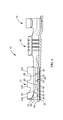
- FIG. 3 is a side view of the terminal of FIG. 1 .
- FIG. 4 is a bottom view of the terminal of FIG. 1 .
- FIG. 5 is a front view of the terminal of FIG. 1 .
- FIG. 6 is a cross-sectional view of the terminal of FIG. 2 , taken along line 6 - 6 .
- FIG. 7 is perspective view of an alternate illustrative embodiment of the terminal according to the present invention.
- a receptacle, socket or female terminal 10 includes a contact portion 12 , a wire barrel 14 behind the contact portion 12 and an insulation barrel 16 behind the wire barrel 14 .
- the wire barrel 14 is configured for crimped connection with an end of a conductive core of an insulated wire.
- the insulation barrel 16 is configured for crimped connection with an end of the insulation coating or jacket of the wire.
- the contact portion 12 can be used with other types of termination members without departing from the scope of the invention.
- the terminal 10 is stamped and formed from a metal plate having a good electrical conductivity.
- the contact portion 12 includes a bottom wall 20 and resilient arms 22 which extend from either side 24 , 26 of the bottom wall 20 .
- the bottom wall 20 has a raised portion 30 with a lead-in surface 34 at the mating end 36 of the contact portion 12 .
- the raised portion 30 provides additional strength and stability to the contact portion 12 .
- the raised portion 30 reinforces the bottom wall 20 to prevent unwanted bending of the terminal, as will be better explained below.
- the raised portion 30 provide increased stiffness to the bottom surface 20 and the contact portion 12 to achieve the desired normal force for the insertion of a mating contact (not shown).
- the raised portion 30 provides a distribution of mechanical stresses, thereby reducing or eliminating the need for an assist spring to help create the required normal force for mating.
- the raised portion 30 is a rectangular platform which provides sufficient stiffness to the terminal 10 to properly control the geometry of the terminal 10 as the mating terminal is inserted therein.
- Embossments such as, but not limited to detents, dimples or lance-through raised shapes 32 are positioned on the raised portion 30 proximate the mating end 36 .
- the embossments 32 are stamped or coined from the raised portion 30 of the bottom wall 20 .
- the embossments 32 extend from the bottom wall 20 to create raised bumps on the inner surface 37 of the bottom wall 20 .
- the embossments 32 are spaced apart and engage the mating terminal as the mating terminal is inserted into the terminal 10 , as will be more fully described. While two embossments 32 are shown, other numbers and configurations of the embossments 32 can be used. In the embodiment shown, the embossments 32 have an oval configuration, although other configurations may be used.
- the embossments 32 may also be in the form of elongated dimples or ribs.
- FIG. 7 illustrates and alternative embodiment in which the embossment is a rib 39 .
- the rib 39 provides additional strength and stability to the contact portion 12 .
- the rib 39 reinforces the bottom wall 20 to prevent unwanted bending of the terminal.
- the rib 39 is a thin, generally rectangular member which extends transversely to the longitudinal axis of the contact portion 12 , creating an indent on the outer surface 33 of the bottom wall 20 and a raised bump 35 on the inner surface 37 of the bottom wall 20 .
- other configurations of the rib 39 may be used to provide the required strengthening properties.
- the rib may be provided proximate the mating end and/or spaced from the mating end.
- An embossment such as, but not limited to detent, dimple or lance-through raised shape 38 is positioned on the raised portion 30 proximate the wire barrel 14 .
- the embossment 38 is stamped or coined from the raised portion 30 of the bottom wall 20 .
- the embossment 38 extends from the bottom wall 20 to create raised bumps on the inner surface 37 of the bottom wall 20 .
- the embossment 38 is spaced apart from the embossments 32 and engages the mating terminal as the mating terminal is inserted into the terminal 10 , as will be more fully described. While one embossment 38 is shown, other numbers and configurations of the embossment 30 can be used. In the embodiment shown, the embossments 38 have an oval configuration, although other configurations may be used. For example, the embossment 38 may also be in the form of elongated dimples or ribs.
- the raised portion 30 also includes an embossment, such as, but not limited to a detent, dimple or lance-through raised shape 40 provided thereon.
- the embossment 40 extends from the bottom wall 20 to create a raised portion or arm extending from the inner surface 37 of the bottom wall 20 toward the resilient arms 22 .
- the embossment 40 engages the mating terminal as the mating terminal is inserted into the terminal 10 , as will be more fully described below.
- the embossment 40 may be stamped, coined or formed from the bottom wall 20 or a spring arm 42 .
- a spring arm 42 may also be provided on the bottom wall 20 .
- the spring arm 42 is stamped and formed from the raised portion 30 .
- Spring arm 42 may have a U-shaped configuration, as shown in FIG. 4 , or may have numerous other configurations, such as, but not limited, to rectangular or round.
- the spring arm 42 is formed to allow a free end 43 thereof to move or be resiliently deformed relative to the bottom wall 20 , allowing the spring arm 42 to move toward and away from the resilient arms 22 .
- the spring arm 42 has the embossment 40 provided thereon.
- the embossment 40 extends from the spring arm 42 to create a raised portion which extends from the inner surface of the spring arm 42 toward the mating terminal engaging member 50 .
- the embossment 40 is provided proximate to, but spaced from, the free end 43 of the spring arm 42 .
- three resilient arms 22 extend from either side 24 , 26 of the bottom wall 20 .
- the first resilient arm 22 a is positioned proximate the mating end 36 of the contact portion 12 .
- the resilient arms 22 a , 22 b , 22 c have arcuate or curled portions 48 which extend from the bottom wall 20 to a mating terminal engaging member 50 , as best shown in FIGS. 1 and 6 .
- the mating terminal engagement members 50 are asymmetrical in the illustrative embodiment shown, having lead-in surfaces 44 positioned proximate the mating end 36 .
- the lead-in surfaces 44 are provided to help guide the mating terminal into the mating slot 46 of the contact portion 12 and to reduce the insertion force required to insert the mating terminal into the slot 46 .
- a mating terminal engagement surface 52 is provided on each mating terminal engaging member 50 .
- the mating terminal engaging member 50 extends from the arcuate portions 48 toward the bottom wall in a direction which is essentially perpendicular to the plane of the bottom wall 20 , positioning the mating terminal engagement surface 52 at the top of the mating slot 46 .
- the configuration of the arcuate portions 48 provide the resiliency needed to allow the mating terminal engaging member 50 to move relative to the bottom wall 20 as the mating terminal is inserted into the slot 46 . This allows for the contact portion 12 to compensate for any slight misalignment of the mating terminal or any slight warpage or imperfections associated with the mating terminal.
- the embossment 40 , the embossments 32 , 38 and the mating terminal engagement surfaces 52 are all provided in electrical and mechanical contact with the mating terminal.
- the multiple areas of contact allow the receptacle contact 10 to be used in applications in which higher current levels, such as, but not limited to, 15 to 20 or more amps.
- the configuration of the embossment, 40 , embossments 32 , 38 and mating terminal engagement surfaces 52 provide for higher hertzian stresses, thereby eliminating or minimizing the fretting corrosion between the mating terminal 10 , thereby providing a stable and reliable electrical connection between the mating terminal and the terminal 10 .
- the embossments 40 , the embossments 32 , 38 and the mating terminal engagement surfaces 52 are spaced laterally relative to each other, allowing the connection between the mating terminal and the receptacle terminal 10 to be stable in all environments, thereby insuring that the mating terminal will remain properly positioned in the receptacle terminal 10 as vibration occurs.
- the receptacle terminal 10 provides multiple contact areas even if the mating terminal is bent, causing the mating terminal to not engage a particular area.
- the multiple contact areas resist twisting or misalignment of the mating terminal.
- the resilient arms 22 are configured such that the contact areas of the mating terminal engagement surfaces 52 generate an equal and opposite force to resist the force generated by the free end 43 of the spring arm 42 and the embossment 40 and the embossments 32 , 38 .
- the resilient arms 22 are configured such that contact areas of the free end 43 of the spring arm 42 and the embossment 40 and the contact areas of the embossments 32 , 38 generate an equal and opposite force to resist the force generated by the mating terminal engagement surfaces 52 .
- the configuration of the resilient arms 22 may be varied to allow the contact areas to have varied forces associated therewith.
- the positioning of the embossment 40 and the embossments 32 , 38 can alter the force applied by each contact area.
- the embossment 40 and the embossments 32 , 38 are transversely offset relative to the path of insertion of the mating terminal, the plating wear on the mating terminal at any particular area is minimized, as the wear is distributed over different areas.
- the configuration of the bottom wall 20 and the resilient arms 22 and the use of multiple contact areas allows for a lower normal force during mating and unmating of the mating terminal from the receptacle contact 10 .
- the number of contact areas also allows the receptacle contact 10 to be used at higher current levels, as the number of contact areas allows the extreme heat associated with the high current levels to be dispersed, thereby preventing welding of the contact asperities.
- a socket type terminal which maintains a stable geometry is provided, thereby allowing the contact points to be controlled even in environments in which the terminal is subject to vibration and the like.
- the stable electrical connection is provided while allowing for a lower insertion force of the mating terminal into the socket terminal.
Landscapes
- Connector Housings Or Holding Contact Members (AREA)
- Coupling Device And Connection With Printed Circuit (AREA)
Abstract
Description
Claims (15)
Priority Applications (2)
| Application Number | Priority Date | Filing Date | Title |
|---|---|---|---|
| US15/479,589 US10103469B1 (en) | 2017-04-05 | 2017-04-05 | Receptacle terminal with stable contact geometry |
| PCT/IB2018/051979 WO2018185595A1 (en) | 2017-04-05 | 2018-03-23 | Receptacle terminal with stable contact geometry |
Applications Claiming Priority (1)
| Application Number | Priority Date | Filing Date | Title |
|---|---|---|---|
| US15/479,589 US10103469B1 (en) | 2017-04-05 | 2017-04-05 | Receptacle terminal with stable contact geometry |
Publications (2)
| Publication Number | Publication Date |
|---|---|
| US20180294588A1 US20180294588A1 (en) | 2018-10-11 |
| US10103469B1 true US10103469B1 (en) | 2018-10-16 |
Family
ID=62002174
Family Applications (1)
| Application Number | Title | Priority Date | Filing Date |
|---|---|---|---|
| US15/479,589 Active US10103469B1 (en) | 2017-04-05 | 2017-04-05 | Receptacle terminal with stable contact geometry |
Country Status (2)
| Country | Link |
|---|---|
| US (1) | US10103469B1 (en) |
| WO (1) | WO2018185595A1 (en) |
Cited By (4)
| Publication number | Priority date | Publication date | Assignee | Title |
|---|---|---|---|---|
| US20180138601A1 (en) * | 2016-11-11 | 2018-05-17 | Autonetworks Technologies, Ltd. | Cable mounting member, cable mounting member with cable and connector |
| US20220045452A1 (en) * | 2020-08-05 | 2022-02-10 | Aptiv Technologies Limited | Anti-fretting/multiple contact terminal using knurl pattern |
| US11264735B1 (en) * | 2020-08-28 | 2022-03-01 | TE Connectivity Services Gmbh | Electrical terminal for terminating a wide size range of magnet wires |
| US11646510B2 (en) | 2021-04-29 | 2023-05-09 | Aptiv Technologies Limited | Shielding electrical terminal with knurling on inner contact walls |
Families Citing this family (2)
| Publication number | Priority date | Publication date | Assignee | Title |
|---|---|---|---|---|
| EP3883070A1 (en) * | 2020-03-18 | 2021-09-22 | Tyco Electronics UK Ltd | Electrical splitter and assembly method |
| USD1049044S1 (en) * | 2022-06-17 | 2024-10-29 | Inteva Products, Llc | Receptacle terminal |
Citations (31)
| Publication number | Priority date | Publication date | Assignee | Title |
|---|---|---|---|---|
| US2768361A (en) * | 1955-07-01 | 1956-10-23 | Ark Les Switch Corp | Connectors |
| US2774951A (en) * | 1954-12-16 | 1956-12-18 | Aircraft Marine Prod Inc | Terminal clip |
| US2787774A (en) * | 1954-01-08 | 1957-04-02 | Martines Rene | Electrical connector |
| US2888662A (en) * | 1954-03-04 | 1959-05-26 | Amp Inc | Electrical connector |
| US2921287A (en) * | 1957-01-18 | 1960-01-12 | Burndy Corp | Snap fit interlocking connector |
| US3086193A (en) * | 1960-12-08 | 1963-04-16 | Berg Quentin | Electrical connector |
| US3152856A (en) * | 1962-11-13 | 1964-10-13 | Kent J Batcheller | Female electric connector member |
| US3204214A (en) | 1963-04-26 | 1965-08-31 | Eisert Josef | Electrical connector |
| US3228207A (en) * | 1961-12-05 | 1966-01-11 | Grote & Hartmann | Electrical connectors |
| US3320574A (en) | 1963-02-04 | 1967-05-16 | Tuchel Ulrich | Two-piece connector |
| US3546663A (en) | 1968-12-19 | 1970-12-08 | Centre William Holmberg Jr | Connector assembly and tool |
| US3550069A (en) * | 1967-06-06 | 1970-12-22 | Amp Inc | Electrical connector tab receptacles |
| US3729701A (en) * | 1970-10-03 | 1973-04-24 | Amp Inc | Longitudinal top spring receptacle |
| DE7807279U1 (en) | 1978-03-10 | 1978-08-10 | Grote & Hartmann Gmbh & Co Kg, 5600 Wuppertal | Flat receptacle |
| US4174878A (en) | 1977-10-07 | 1979-11-20 | Cgee Alsthom | Security structure for positioning a clip on a connector tab |
| US4220388A (en) * | 1977-09-09 | 1980-09-02 | Helen Dechelette | Electrical connector and contact and housing therefor |
| US4415221A (en) | 1980-10-01 | 1983-11-15 | Tokai Electrie Wire Company Limited | Female type electrical connector |
| US4445745A (en) | 1980-12-24 | 1984-05-01 | Societe Generale Pour L'industrie Electronique (S.O.G.I.E.) | Electrical connectors for coaxial and two-wire cables |
| US4448468A (en) * | 1982-07-09 | 1984-05-15 | Amp Incorporated | Receptacle terminal having latching feature |
| US4534613A (en) * | 1983-10-31 | 1985-08-13 | Amp Incorporated | Receptacle terminal having locking lance |
| US5295874A (en) * | 1992-04-30 | 1994-03-22 | Yazaki Corporation | Weak mating force female terminal |
| EP0602681A2 (en) | 1992-12-18 | 1994-06-22 | The Whitaker Corporation | Receptacle terminal having retention means |
| US5395270A (en) * | 1992-10-01 | 1995-03-07 | Yazaki Corporation | Weak mating force female terminal |
| US5733154A (en) * | 1995-03-09 | 1998-03-31 | Berg Technology, Inc. | Connector element for connecting a flexfoil and a pin-like contact member and a related connected tool and method |
| US6039615A (en) | 1996-03-15 | 2000-03-21 | The Whitaker Corporation | Female electrical terminal having overstress members |
| US6068526A (en) * | 1996-06-17 | 2000-05-30 | Framatome Connectors International | Connector bushing having an improved central base zone |
| US6293831B1 (en) * | 1998-04-16 | 2001-09-25 | Calsonic Kansei Corporation | Electric connector |
| US6997746B2 (en) | 2004-04-20 | 2006-02-14 | Ark-Les Corporation | Crimp connector |
| US7166002B2 (en) | 2004-06-14 | 2007-01-23 | Yazaki Corporation | Connection terminal |
| US7255614B1 (en) * | 2006-06-30 | 2007-08-14 | Illinois Tool Works Inc | Electrical terminal |
| US7845993B2 (en) * | 2009-01-23 | 2010-12-07 | Mta S.P.A. | Female electrical terminal |
-
2017
- 2017-04-05 US US15/479,589 patent/US10103469B1/en active Active
-
2018
- 2018-03-23 WO PCT/IB2018/051979 patent/WO2018185595A1/en not_active Ceased
Patent Citations (31)
| Publication number | Priority date | Publication date | Assignee | Title |
|---|---|---|---|---|
| US2787774A (en) * | 1954-01-08 | 1957-04-02 | Martines Rene | Electrical connector |
| US2888662A (en) * | 1954-03-04 | 1959-05-26 | Amp Inc | Electrical connector |
| US2774951A (en) * | 1954-12-16 | 1956-12-18 | Aircraft Marine Prod Inc | Terminal clip |
| US2768361A (en) * | 1955-07-01 | 1956-10-23 | Ark Les Switch Corp | Connectors |
| US2921287A (en) * | 1957-01-18 | 1960-01-12 | Burndy Corp | Snap fit interlocking connector |
| US3086193A (en) * | 1960-12-08 | 1963-04-16 | Berg Quentin | Electrical connector |
| US3228207A (en) * | 1961-12-05 | 1966-01-11 | Grote & Hartmann | Electrical connectors |
| US3152856A (en) * | 1962-11-13 | 1964-10-13 | Kent J Batcheller | Female electric connector member |
| US3320574A (en) | 1963-02-04 | 1967-05-16 | Tuchel Ulrich | Two-piece connector |
| US3204214A (en) | 1963-04-26 | 1965-08-31 | Eisert Josef | Electrical connector |
| US3550069A (en) * | 1967-06-06 | 1970-12-22 | Amp Inc | Electrical connector tab receptacles |
| US3546663A (en) | 1968-12-19 | 1970-12-08 | Centre William Holmberg Jr | Connector assembly and tool |
| US3729701A (en) * | 1970-10-03 | 1973-04-24 | Amp Inc | Longitudinal top spring receptacle |
| US4220388A (en) * | 1977-09-09 | 1980-09-02 | Helen Dechelette | Electrical connector and contact and housing therefor |
| US4174878A (en) | 1977-10-07 | 1979-11-20 | Cgee Alsthom | Security structure for positioning a clip on a connector tab |
| DE7807279U1 (en) | 1978-03-10 | 1978-08-10 | Grote & Hartmann Gmbh & Co Kg, 5600 Wuppertal | Flat receptacle |
| US4415221A (en) | 1980-10-01 | 1983-11-15 | Tokai Electrie Wire Company Limited | Female type electrical connector |
| US4445745A (en) | 1980-12-24 | 1984-05-01 | Societe Generale Pour L'industrie Electronique (S.O.G.I.E.) | Electrical connectors for coaxial and two-wire cables |
| US4448468A (en) * | 1982-07-09 | 1984-05-15 | Amp Incorporated | Receptacle terminal having latching feature |
| US4534613A (en) * | 1983-10-31 | 1985-08-13 | Amp Incorporated | Receptacle terminal having locking lance |
| US5295874A (en) * | 1992-04-30 | 1994-03-22 | Yazaki Corporation | Weak mating force female terminal |
| US5395270A (en) * | 1992-10-01 | 1995-03-07 | Yazaki Corporation | Weak mating force female terminal |
| EP0602681A2 (en) | 1992-12-18 | 1994-06-22 | The Whitaker Corporation | Receptacle terminal having retention means |
| US5733154A (en) * | 1995-03-09 | 1998-03-31 | Berg Technology, Inc. | Connector element for connecting a flexfoil and a pin-like contact member and a related connected tool and method |
| US6039615A (en) | 1996-03-15 | 2000-03-21 | The Whitaker Corporation | Female electrical terminal having overstress members |
| US6068526A (en) * | 1996-06-17 | 2000-05-30 | Framatome Connectors International | Connector bushing having an improved central base zone |
| US6293831B1 (en) * | 1998-04-16 | 2001-09-25 | Calsonic Kansei Corporation | Electric connector |
| US6997746B2 (en) | 2004-04-20 | 2006-02-14 | Ark-Les Corporation | Crimp connector |
| US7166002B2 (en) | 2004-06-14 | 2007-01-23 | Yazaki Corporation | Connection terminal |
| US7255614B1 (en) * | 2006-06-30 | 2007-08-14 | Illinois Tool Works Inc | Electrical terminal |
| US7845993B2 (en) * | 2009-01-23 | 2010-12-07 | Mta S.P.A. | Female electrical terminal |
Non-Patent Citations (1)
| Title |
|---|
| U.S. Appl. No. 15/479,644, filed Apr. 5, 2017. |
Cited By (7)
| Publication number | Priority date | Publication date | Assignee | Title |
|---|---|---|---|---|
| US20180138601A1 (en) * | 2016-11-11 | 2018-05-17 | Autonetworks Technologies, Ltd. | Cable mounting member, cable mounting member with cable and connector |
| US10476178B2 (en) * | 2016-11-11 | 2019-11-12 | Autonetworks Technologies, Ltd. | Cable mounting member, cable mounting member with cable and connector |
| US20220045452A1 (en) * | 2020-08-05 | 2022-02-10 | Aptiv Technologies Limited | Anti-fretting/multiple contact terminal using knurl pattern |
| US11387585B2 (en) * | 2020-08-05 | 2022-07-12 | Aptiv Technologies Limited | Anti-fretting/multiple contact terminal using knurl pattern |
| US11264735B1 (en) * | 2020-08-28 | 2022-03-01 | TE Connectivity Services Gmbh | Electrical terminal for terminating a wide size range of magnet wires |
| US20220069482A1 (en) * | 2020-08-28 | 2022-03-03 | TE Connectivity Services Gmbh | Electrical terminal for terminating a wide size range of magnet wires |
| US11646510B2 (en) | 2021-04-29 | 2023-05-09 | Aptiv Technologies Limited | Shielding electrical terminal with knurling on inner contact walls |
Also Published As
| Publication number | Publication date |
|---|---|
| US20180294588A1 (en) | 2018-10-11 |
| WO2018185595A1 (en) | 2018-10-11 |
Similar Documents
| Publication | Publication Date | Title |
|---|---|---|
| US10103469B1 (en) | Receptacle terminal with stable contact geometry | |
| US10027037B2 (en) | Terminal with reduced normal force | |
| US10079440B1 (en) | Electrical terminal having a push surface | |
| US10211558B1 (en) | Low insertion force tab receptacle | |
| US9099796B2 (en) | Receptacle contact | |
| US10256561B2 (en) | Terminal with ribbed contact spring | |
| US20160087366A1 (en) | Terminals for electrical connectors | |
| US20180323528A1 (en) | Terminal fitting and connector | |
| JP6085709B2 (en) | Female terminal structure | |
| CN114122749B (en) | Electrical terminal for terminating a wide range of magnetic wire sizes | |
| KR20160076567A (en) | Spring of female terminal | |
| US9673548B2 (en) | Contact connection structure | |
| US9716333B1 (en) | Heavy current female connector | |
| US10559897B1 (en) | Push-in electrical terminal with insulation contact | |
| US10819057B1 (en) | Electrical terminal with resilient contact arm with low insertion force and high normal force | |
| US20250286319A1 (en) | Quick Disconnect Terminal With Split Mating Interface | |
| US20250286304A1 (en) | Front-Facing Locking Feature for Quick Connect Terminal | |
| JP5923389B2 (en) | Terminal connection structure | |
| GB2048581A (en) | Electrical socket | |
| JP2017091834A (en) | connector | |
| JP2013114937A (en) | Female terminal structure |
Legal Events
| Date | Code | Title | Description |
|---|---|---|---|
| AS | Assignment |
Owner name: TE CONNECTIVITY CORPORATION, PENNSYLVANIA Free format text: ASSIGNMENT OF ASSIGNORS INTEREST;ASSIGNORS:HUMPHREY, DAVID TRACY;LANDON, RAYMOND L., III;REEL/FRAME:041857/0776 Effective date: 20170331 |
|
| STCF | Information on status: patent grant |
Free format text: PATENTED CASE |
|
| AS | Assignment |
Owner name: TE CONNECTIVITY SERVICES GMBH, SWITZERLAND Free format text: ASSIGNMENT OF ASSIGNORS INTEREST;ASSIGNOR:TE CONNECTIVITY CORPORATION;REEL/FRAME:056524/0226 Effective date: 20180928 Owner name: TE CONNECTIVITY SERVICES GMBH, SWITZERLAND Free format text: CHANGE OF ADDRESS;ASSIGNOR:TE CONNECTIVITY SERVICES GMBH;REEL/FRAME:056524/0531 Effective date: 20191101 |
|
| MAFP | Maintenance fee payment |
Free format text: PAYMENT OF MAINTENANCE FEE, 4TH YEAR, LARGE ENTITY (ORIGINAL EVENT CODE: M1551); ENTITY STATUS OF PATENT OWNER: LARGE ENTITY Year of fee payment: 4 |
|
| AS | Assignment |
Owner name: TE CONNECTIVITY SOLUTIONS GMBH, SWITZERLAND Free format text: MERGER;ASSIGNOR:TE CONNECTIVITY SERVICES GMBH;REEL/FRAME:060885/0482 Effective date: 20220301 |