US10102314B2 - Optimal operation pattern selection method for motor, optimal operation pattern selection program for motor, and motor selection device - Google Patents
Optimal operation pattern selection method for motor, optimal operation pattern selection program for motor, and motor selection device Download PDFInfo
- Publication number
- US10102314B2 US10102314B2 US14/896,834 US201314896834A US10102314B2 US 10102314 B2 US10102314 B2 US 10102314B2 US 201314896834 A US201314896834 A US 201314896834A US 10102314 B2 US10102314 B2 US 10102314B2
- Authority
- US
- United States
- Prior art keywords
- motor
- time
- output shaft
- operation pattern
- rotation
- Prior art date
- Legal status (The legal status is an assumption and is not a legal conclusion. Google has not performed a legal analysis and makes no representation as to the accuracy of the status listed.)
- Active, expires
Links
Images


Classifications
-
- G06F17/5009—
-
- H—ELECTRICITY
- H02—GENERATION; CONVERSION OR DISTRIBUTION OF ELECTRIC POWER
- H02P—CONTROL OR REGULATION OF ELECTRIC MOTORS, ELECTRIC GENERATORS OR DYNAMO-ELECTRIC CONVERTERS; CONTROLLING TRANSFORMERS, REACTORS OR CHOKE COILS
- H02P23/00—Arrangements or methods for the control of AC motors characterised by a control method other than vector control
- H02P23/0004—Control strategies in general, e.g. linear type, e.g. P, PI, PID, using robust control
-
- G—PHYSICS
- G05—CONTROLLING; REGULATING
- G05B—CONTROL OR REGULATING SYSTEMS IN GENERAL; FUNCTIONAL ELEMENTS OF SUCH SYSTEMS; MONITORING OR TESTING ARRANGEMENTS FOR SUCH SYSTEMS OR ELEMENTS
- G05B19/00—Program-control systems
- G05B19/02—Program-control systems electric
- G05B19/18—Numerical control [NC], i.e. automatically operating machines, in particular machine tools, e.g. in a manufacturing environment, so as to execute positioning, movement or co-ordinated operations by means of program data in numerical form
- G05B19/19—Numerical control [NC], i.e. automatically operating machines, in particular machine tools, e.g. in a manufacturing environment, so as to execute positioning, movement or co-ordinated operations by means of program data in numerical form characterised by positioning or contouring control systems, e.g. to control position from one programmed point to another or to control movement along a programmed continuous path
-
- G—PHYSICS
- G06—COMPUTING OR CALCULATING; COUNTING
- G06F—ELECTRIC DIGITAL DATA PROCESSING
- G06F17/00—Digital computing or data processing equipment or methods, specially adapted for specific functions
- G06F17/10—Complex mathematical operations
-
- G—PHYSICS
- G06—COMPUTING OR CALCULATING; COUNTING
- G06F—ELECTRIC DIGITAL DATA PROCESSING
- G06F30/00—Computer-aided design [CAD]
- G06F30/20—Design optimisation, verification or simulation
-
- H—ELECTRICITY
- H02—GENERATION; CONVERSION OR DISTRIBUTION OF ELECTRIC POWER
- H02P—CONTROL OR REGULATION OF ELECTRIC MOTORS, ELECTRIC GENERATORS OR DYNAMO-ELECTRIC CONVERTERS; CONTROLLING TRANSFORMERS, REACTORS OR CHOKE COILS
- H02P29/00—Arrangements for regulating or controlling electric motors, appropriate for both AC and DC motors
Definitions
- the present invention relates to an optimal operation pattern selection method for a motor, an optimal operation pattern selection program for a motor, and a motor selection device.
- Prior Art 1 discloses a servomotor selection device including: a selection unit for a servo system driven by a servomotor; an input unit for mechanical elements of a servo system; an input unit for a movement pattern of a load of a servo system; a calculation unit to acquire required specifications for a servomotor based on output results of the selection unit for a servo system, the input unit for mechanical elements of a servo system, and the input unit for a load movement pattern; and a search unit for a servomotor adaptive to the servo system based on the required specifications acquired in the calculation unit.
- Prior Art 2 discloses a selection system for a drive motor and a reducer in an actuator, in which a minimum reducer capable of driving a load mechanism is temporarily selected first by a computer, subsequently a minimum drive motor capable of driving the reducer temporarily selected as a load mechanism is temporarily selected, next verification is made on whether combination of the load mechanism with the temporarily selected reducer and the temporarily selected drive motor satisfies specifications of the temporarily selected reducer. In the case of not satisfying the specifications, temporary selection of the drive motor and the verification are repeated by increasing the size of the reducer until all of the specifications are satisfied, and an optimal drive motor and an optimal reducer are finally selected at the same time.
- an operation pattern is varied by a purpose of use of a motor, and therefore, a user needs to preliminarily determine and input the operation pattern in accordance with the purpose of use of the motor.
- the motor is selected based on a determination standard whether the selected motor can be used with the operation pattern.
- complex calculation is needed to obtain an optimal operation pattern for each motor, and the motor is selected based on the operation pattern temporarily determined in the technologies of Prior Arts 1 and 2. Therefore, the temporarily determined operation pattern is not constantly the optimal operation pattern which satisfies intention of a user. Further, since the motor is selected based on the temporarily determined operation pattern, the selected motor tends to have excessive performance.
- the present invention is made in view of the above circumstances, and is directed to providing an optimal operation pattern selection method for a motor, an optimal operation pattern selection program for a motor, and a motor selection device, in which manpower to determine an operation pattern for a motor is reduced and selectable motor information is provided.
- an optimal operation pattern selection method for a motor a plurality of selectable motors is selected and an optimal operation pattern is suggested from among motor operation patterns defined by positioning time to rotate a motor output shaft of the motor to rotate a load by a positioning angle and stop time to stop the motor output shaft.
- the optimal operation pattern selection method includes a comprehensive determination step of calculating a comprehensive determination result according to an adaptable item, and storing the comprehensive determination result linked to each of the motors; and a list display step of displaying, together with the comprehensive determination result stored in the comprehensive determination step, a list of the motors to enable to receive selection of one of the motors.
- the method it is possible to estimate, from among the plurality of selectable motors, the motor for which the optimal operation pattern can be selected based on the comprehensive determination result even when the operation pattern for the motor is not determined. Therefore, the operation pattern can be studied upon narrowing down a target of the motor. As a result, possibility that the selected motor has excessive performance can be reduced.
- the optimal operation pattern selection method for a motor is, from among motor operation patterns defined by positioning time to rotate a motor output shaft of the motor to rotate a load by a positioning angle and stop time to stop the motor output shaft, a method of selecting a plurality of selectable motors and suggesting an optimal operation pattern.
- the method preferably includes: a simulation conditions input step of acquiring information of simulation conditions including an input value of the positioning angle and an input value of inertia moment of the load as operating conditions, and at least one of an input value of required positioning time and an input value of required stop time as required conditions; a simulation step of simulating, an operation pattern under the simulation conditions for each of the stored motors based on mechanical elements data information for each of the selectable motors; a comparison step of comparing, with the operating conditions and the required conditions, each operation pattern for each of the motors obtained in the simulation step, comparing each item with a predetermined threshold, and storing an adaptability determination result; a comprehensive determination step of calculating a comprehensive determination result according to an adaptable item obtained in the comparison step, and storing the comprehensive determination result linked to each of the motors; and a list display step of displaying a list of the motors together with the comprehensive determination result stored in the comprehensive determination step.
- the method even when a user does not preliminarily determine an operation pattern in accordance with a purpose of use, it is possible to estimate the motor for which the optimal operation pattern can be selected from among the plurality of selectable motors only based on predetermined input information. Therefore, the operation pattern can be studied upon narrowing down the target of the motor. As a result, possibility that the selected motor has excessive performance can be reduced.
- a determination result indicating partially adaptable is provided as the comprehensive determination result in the comprehensive determination step.
- the user can leave, as a choice, even a motor not satisfying the conditions. Since the motor having a non-adaptable item in the operating conditions is excluded, the motor having no possibility of use is excluded from the choice, and the target of the motor can be narrowed down. Therefore, the user can study the operation pattern for the motor by reconsidering the operation pattern. As a result, possibility that the selected motor has excessive performance can be reduced.
- the determination result indicating partially adaptable is displayed on the list of the motors in the list display step.
- an operator can grasp a choice of the adaptable motor at a glance.
- the simulation step is executed under the condition that the input value of the positioning angle, the input value of the inertia moment of the load, the input value of the required positioning time or the input value of the required stop time are input in the simulation conditions input step.
- the simulation step includes: calculating a total value of inertia moment by adding rotor inertia moment of the mechanical elements data information with the input value of the inertia moment of the load; and acquiring shortest positioning time to rotate the load by the input value of the positioning angle based on the total value of the inertia moment and torque characteristic information according to a rotational angular speed or a rotational speed included in the mechanical elements data information, and simulating an operation pattern having the shortest positioning time for each of the motors.
- the operation pattern that can shorten cycle time by minimizing time to complete positioning can be simulated.
- an operation pattern is simulated such that rotation by the positioning angle is performed by rotation of the output shaft during acceleration time in which rotation of the motor output shaft is accelerated and during deceleration time in which rotation of the motor output shaft is decelerated.
- the operation pattern that can shorten cycle time by minimizing time to complete positioning can be simulated.
- an operation pattern is simulated in a first area where a rotational angular speed or a rotational speed changes to the break point such that rotation by the positioning angle is performed by rotation of the output shaft during the acceleration time in which rotation of the motor output shaft is accelerated and deceleration time in which rotation of the motor output shaft is decelerated.
- the operation pattern that minimizes the time to complete positioning can be simulated with high accuracy even when there is a torque characteristic in which the more increased the rotational angular speed or the rotational speed of the motor is, the more phenomenon the torque is.
- positioning time to rotate the motor output shaft in the second area is shortest positioning time among positioning time calculated for each of sections obtained by dividing the second area into a plurality of the sections.
- the input value of the required positioning time is input in the simulation conditions input step, and the input value of the required positioning time is input as the threshold, the shortest positioning time is compared with the threshold, and the adaptability determination result is stored in the comparison step.
- the optimal operation pattern for the motor which can minimize the time to complete positioning, can be studied. As a result, possibility that the selected motor has excessive performance can be reduced.
- an optimal operation pattern selection program for a motor in the optimal operation pattern selection method for a motor causes a computer to execute processing including the comprehensive determination step and the list display step.
- the program it is possible to estimate the motor for which the optimal operation pattern can be selected from among the plurality of selectable motors based on the comprehensive determination result even when the operation pattern for the motor is not determined. Therefore, the operation pattern can be studied upon narrowing down a target of the motor. As a result, possibility that the selected motor has excessive performance can be reduced.
- a motor selection device is configured to select a plurality of selectable motors and suggest an optimal operation pattern from among motor operation patterns defined by positioning time to rotate a motor output shaft of the motor to rotate a load by a positioning angle and stop time to stop the motor output shaft.
- the motor selection device includes a calculation unit configured to compare each item with a predetermined threshold, and calculate a comprehensive determination result according to the item obtained as adaptable; and an information output unit configured to output, by linking the comprehensive determination result to each of the motors, information of a list of the motors to enable to receive selection of one of the motors from an input access unit.
- the configuration it is possible to estimate the motor for which the optimal operation pattern can be selected from among the plurality of selectable motors based on the comprehensive determination result even when the operation pattern for the motor is not determined. Therefore, the operation pattern can be studied upon narrowing down a target of the motor. As a result, possibility that the selected motor has excessive performance can be reduced.
- a motor selection device is configured to select a plurality of selectable motors and suggest an optimal operation pattern from among motor operation patterns defined by positioning time to rotate a motor output shaft of the motor to rotate a load by a positioning angle and stop time to stop the motor output shaft.
- the motor selection device preferably includes: an input access unit to perform input receiving processing for information of simulation conditions including at least one of an input value of the positioning angle and an input value of inertia moment of the load as operating conditions, and an input value of required positioning time and an input value of required stop time as required conditions; a storage unit to store mechanical elements data information for each of the selectable motors; a calculation unit to simulate, for each of the stored motors, an operation pattern under the simulation conditions, compare the obtained operation pattern for each of the motors with the operating conditions and the required conditions, compare each item with a predetermined threshold, and calculate a comprehensive determination result according to the item obtained as adaptable; and an information output unit to output information of a list of the motors by linking the comprehensive determination result to each of the motors.
- the configuration even when the user does not preliminarily determine the operation pattern in accordance with the purpose of use, it is possible to estimate the motor for which the optimal operation pattern can be selected from among the plurality of selectable motors only based on predetermined input information. Therefore, the operation pattern can be studied upon narrowing down a target of the motor. As a result, possibility that the selected motor has excessive performance can be reduced.
- the calculation unit in the case where an item of the operation conditions is adaptable and an item of the required conditions is not adaptable, the calculation unit provides a determination result indicating partially adaptable as the comprehensive determination result.
- the user can leave, as a choice, even a motor not satisfying the conditions. Since the motor having a non-adaptable item in the operating conditions is excluded, the motor having no possibility of use is excluded from the choice, and the target of the motor can be narrowed down. Therefore, the user can study the operation pattern for the motor by reconsidering the operation pattern. As a result, possibility that the selected motor has excessive performance can be reduced.
- the information output unit outputs information including the determination result indicating partially adaptable in the list of the motors.
- assistance can be provided such that the operator can grasp the choices of the adaptable motor at a glance.
- the calculation unit performs calculation processing to simulate the operation pattern under the condition that the input value of the positioning angle, the input value of the inertia moment of the load, the input value of the required positioning time, or the input value of the required stop time are input.
- assistance to reduce a burden of calculation on the operator can be provided because the motor is selected based on the simulated operation pattern.
- the calculation unit calculates a total value of inertia moment by adding rotor inertia moment of the mechanical elements data information with the input value of the inertia moment of the load, acquires shortest positioning time to rotate the load by the input value of the positioning angle based on the total value of the inertia moment and torque characteristic information according to a rotational angular speed or a rotational speed included in the mechanical elements data information, and simulates an operation pattern having the shortest positioning time for each of the motors.
- the operation pattern that can shorten the cycle time by minimizing the time to complete positioning can be simulated.
- an optimal operation pattern selection method for a motor a non-transitory computer-readable storage medium that stores therein an optimal operation pattern selection program to select optimum operation pattern of a motor for a motor selection device, and a motor selection device, in which manpower to determine an operation pattern for a motor is reduced and selectable motor information is provided.
- FIG. 1 is a diagram illustrating a configuration of a motor selection device according to the present embodiment.
- FIG. 2 is an explanatory diagram illustrating a use state of a motor according to the present embodiment.
- FIG. 3 is an explanatory diagram illustrating components to be mounted on the motor according to the present embodiment.
- FIG. 4 is a flowchart illustrating an exemplary operating procedure of an optimal operation pattern selection method for a motor executed by the motor selection device according to the present embodiment.
- FIG. 5 is an explanatory diagram illustrating an exemplary input screen of the motor selection device according to the present embodiment.
- FIG. 6 is an explanatory diagram illustrating an exemplary operation pattern of a motor according to the present embodiment.
- FIG. 7 is an explanatory diagram illustrating an exemplary relation between output torque in the case of having no dynamic friction torque and output torque in the case of having dynamic friction torque.
- FIG. 8 is an explanatory diagram illustrating an exemplary relation between output torque in the case of having no constant load torque and output torque in the case of having constant load torque.
- FIG. 9 is an explanatory diagram illustrating an exemplary flowchart to calculate an operation pattern for a motor according to the present embodiment.
- FIG. 10 is an explanatory diagram illustrating an exemplary motor database storing mechanical elements data information for each of selectable motors according to the present embodiment.
- FIG. 11 is an explanatory diagram illustrating first torque characteristic information (N-T characteristic) in the motor according to the present embodiment.
- FIG. 12 is an explanatory diagram illustrating second torque characteristic information (N-T characteristic) in the motor according to the present embodiment.
- FIG. 13 is an explanatory diagram illustrating third torque characteristic information (N-T characteristic) in the motor according to the present embodiment.
- FIG. 14 is an explanatory diagram illustrating an approximate formula to obtain shortest positioning time by approximating the third torque characteristic information (N-T characteristic) illustrated in FIG. 13 .
- FIG. 15 is an explanatory diagram illustrating the third torque characteristic information (N-T characteristic) illustrated in FIG. 13 to describe divisions of rotational angular speed to acquire output torque according to the speed.
- FIG. 16 is an explanatory diagram illustrating another example of the operation pattern for a motor according to the present embodiment.
- FIG. 17 is an explanatory diagram illustrating another example of an input screen of the motor selection device according to the present embodiment.
- FIG. 18 is a flowchart illustrating an operation pattern simulation step to simulate an operation pattern for a motor.
- FIG. 19 is a flowchart illustrating a comparison step with the operation conditions and required conditions.
- FIG. 20 is an explanatory diagram illustrating an output display screen to display exemplary items compared in the comparison step using the operating conditions and the required conditions, and exemplary determination results.
- FIG. 21 is an explanatory diagram illustrating an output display screen to display an exemplary comprehensive determination result.
- FIG. 22 is an explanatory diagram illustrating a modified example in which the motor selection device according to the present embodiment is configured as a client server system via a network.
- FIG. 1 is a diagram illustrating a configuration of a motor selection device according to the present embodiment.
- a motor selection device 1 includes a control device 11 , an input device 12 , a display device 13 , and an external storage device 15 .
- the control device 11 has a communication control device 14 g which is connectable to a network 2 .
- the input device 12 is an input access unit such as a mouse and a keyboard, and receives input operation and select operation by a designer who is an operator (user), and outputs an input signal to the control device 11 .
- the display device 13 is a device to display an image, such as a cathode ray tube (CRT) and a liquid crystal display, and also is an information output unit.
- CTR cathode ray tube
- the control device 11 is a computer such as a personal computer (PC) and a server system, and includes an input interface 14 a , an output interface 14 b , a central processing unit (CPU) 14 c , a read only memory (ROM) 14 d , a random access memory (RAM) 14 e , an internal storage device 14 f , the communication control device 14 g , and an internal bus 14 h .
- the input interface 14 a , output interface 14 b , CPU 14 c , ROM 14 d , RAM 14 e , internal storage device 14 f , and communication control device 14 g are connected via the internal bus 14 h.
- the input interface 14 a receives an input signal from the input device 12 , and outputs the input signal to the CPU 14 c .
- the output interface 14 b receives an image signal from the CPU 14 c , and outputs the image signal to the display device 13 .
- the ROM 14 d stores a program such as a basic input output system (BIOS).
- the internal storage device 14 f is, for example, a hard disk drive (HDD), a flash memory, or the like, and stores an operating system program, an application program, and an optimal operation pattern selection program for a motor according to the present embodiment.
- the CPU 14 c is a calculation unit, and implements various kinds of functions by executing programs stored in the ROM 14 d and internal storage device 14 f while using the RAM 14 e as a work area.
- the external storage device 15 is an HDD, a server, or the like.
- the internal storage device 14 f or the external storage device 15 stores motor database storing mechanical elements data information for each of selectable motors.
- the mechanical elements data information includes, for each of the selectable motors, information containing a rotor inertia moment, a rotational speed-torque characteristic (N-T characteristic), rated torque, seal friction torque, a maximum rotational speed (maximum rotational angular speed), a break point speed, and maximum output torque, which are linked one another.
- the internal storage device 14 f or the external storage device 15 functions as a storage unit.
- the rotational speed-torque characteristic (N-T characteristic) may be stored in the internal storage device 14 f or the external storage device 15 as rotational angular speed-torque characteristic data.
- FIG. 2 is an explanatory diagram illustrating a use state of a motor according to the present embodiment.
- a motor 20 is fixed to a support member 51 , and used as a load body 50 mounted with a conveying plate 52 that moves a conveyed object 53 in a manner rotatable around a rotary axis Zr in an R direction of either normal rotation or reverse rotation, for example.
- the conveyed object 53 is, for example, a component such as a light emitting diode, a ceramic capacitor, a chip resistor, and an on-vehicle integrated circuit.
- the motor 20 determines a position of the conveyed object 53 conveyed by the conveying plate 52 in accordance with a position of a motor output shaft 21 .
- the motor 20 can directly transmit rotational force to the conveyed object 53 and the conveying plate 52 , namely, the load body 50 without interposing a transmission mechanism such as a gear, a belt, or a roller, and can rotate the conveyed object 53 .
- the motor 20 is a so-called direct drive motor in which a motor rotary shaft and the load body 50 are directly connected. With this configuration, the motor 20 can determine the position of conveyed object 53 with high accuracy.
- a motor control circuit 90 when a motor rotation command i is received from an external computer, a motor control circuit 90 outputs a drive signal from a control unit (central processing unit (CPU)) 91 to a three-phase amplifier (amplifier (AMP)) 92 in accordance with an operation pattern stored in a storage unit 94 .
- the motor control circuit 90 supplies the motor 20 with drive current Mi from the AMP 92 via a wire.
- the motor 20 rotates the conveying plate 52 by the drive current Mi so as to move the conveyed object 53 .
- a rotation angle detector such as a resolver 95 detects a rotation angle and outputs a detection signal (resolver signal) Sr.
- the motor control circuit 90 receives the detection signal Sr and digitally converts the received detection signal Sr by a resolver- 5 to-digital converter (RDC) 93 .
- the CPU 91 determines whether the conveyed object 53 has reached a commanded position based on digital information of the detection signal Sr from the RDC 93 . In the case that the conveyed object 53 has 10 reached the commanded position, the drive signal to the AMP 92 is stopped.
- inertia moment of the load body 50 is added to the motor output shaft 21 of the motor 20 in accordance with number, a shape, mass, and a size of the conveyed object 53 and a shape, mass, and a size of the conveying plate 52 .
- the inertia moment of a load by the load body 50 is a sum of the inertia moment of the load mounted on the motor 20 , and magnitude of the inertia moment of the load influences acceleration/deceleration characteristics. Therefore, in the case of selecting an operation pattern for a motor and the motor, it is necessary to consider the inertia moment of the load by the load body 50 . Further, FIG.
- FIG. 3 is an explanatory diagram illustrating components to be mounted on the motor according to the present embodiment. As illustrated in FIG. 3 , there may be a case where a bearing 54 to support the conveying plate 52 and an oil seal 55 are mounted on the motor 20 besides the conveying plate 52 and the conveyed object 53 , and dynamic friction torque may be caused at the motor output shaft 21 of the motor 20 .
- an operation pattern is varied by a purpose of use of the motor.
- the operation pattern is required to satisfy one of following conditions: a period during which the motor is rotated is shortest; a period during which the motor is needed to be stopped is shortest; effective torque of the motor is minimized; an acceleration/deceleration speed is maximized; and rotational speed (rotational angular speed) is a constant speed or less.
- a user of a motor may not be always familiar with a motor to be selected, and a large burden may be imposed on the user to verify whether a result of a calculated operation pattern is an optimal operation pattern for the selected motor although the operation pattern is calculated by the user himself or herself. Further, a large burden may be imposed on the user of the motor to make adjustment such that the result of the calculated operation pattern becomes the optimal operation pattern for the selected motor. Therefore, when the user of the motor reduces such burdens by selecting a motor having excessive performance, cost for the motor may be increased.
- a motor selection device executes an optimal operation pattern selection program for a motor illustrated in FIG. 4 , and performs an optimal operation pattern selection method.
- FIG. 4 is a flowchart illustrating an exemplary operating procedure of the optimal operation pattern selection method for a motor executed by the motor selection device according to the present embodiment.
- FIG. 5 is an explanatory diagram illustrating an exemplary input screen of the motor selection device according to the present embodiment.
- the display device 13 displays an input screen G 1 to the user.
- the CPU 14 c of the control device 11 receives respective input values in a box B 1 at conditions 1 among the simulation conditions input from the input device 12 .
- the CPU 14 c can receive an input value C 11 of a positioning angle, an input value C 12 of required positioning time, an input value C 13 of required stop time, an input value C 14 of a torque limit, and an input value C 15 of a maximum rotational speed limit, which are input from the input device 12 , and then stores the input values in the external storage device 15 or the internal storage device 14 f as the information of the simulation conditions.
- the CPU 14 c of the control device 11 receives respective input values in a box B 2 of conditions 2 illustrated in FIG. 5 among the simulation conditions input from the input device 12 .
- the CPU 14 c receives one or more of an input value C 21 of the inertia moment of the load, an input value C 22 of load torque (constant), and an input value C 23 of dynamic friction torque, which are input from the input device 12 , and then the CPU 14 c stores the input values in the external storage device 15 or the internal storage device 14 f as the information of the simulation conditions.
- FIG. 6 is an explanatory diagram illustrating an exemplary operation pattern for the motor according to the present embodiment.
- the rotational speed of the motor is accelerated during acceleration time ta.
- the rotational speed of the motor is kept at the maximum rotational speed Nmax during constant speed time tc.
- the rotational speed of the motor is reduced and decelerated during deceleration time td.
- the rotational speed of the motor becomes zero and the motor is stopped during stop time tb.
- Positioning time te is a period obtained by adding the acceleration time ta with the constant speed time tc and deceleration time td.
- the above-mentioned input value C 12 of the requested positioning time corresponds to a value of the positioning time te.
- the input value C 13 of the required stop time corresponds to the stop time tb.
- the input value C 15 of the maximum rotational speed limit corresponds to the maximum rotational speed Nmax.
- the direct drive motor performs positioning operation by alternately setting the positioning time to rotate the motor output shaft 21 and the stop time to stop the motor output shaft 21 .
- the operation pattern illustrated in FIG. 6 different from the case where the motor is used at a constant rotational speed and constant load torque, it is necessary to consider how constant load torque Tm and dynamic friction torque Ti influence output torque in accordance with behavior of the motor at the time of calculating effective torque Te.
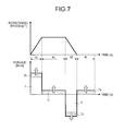
- FIG. 7 is an explanatory diagram illustrating an exemplary relation between output torque in the case of having no dynamic friction torque and output torque in the case of having dynamic friction torque.
- FIG. 8 is an explanatory diagram illustrating an exemplary relation between output torque in the case of having no constant load torque and output torque in the case of having constant load torque.
- the dynamic friction torque Ti is added to the output torque T during normal rotation, and the dynamic friction torque Ti is subtracted from the output torque T during reverse rotation.
- the dynamic friction torque Ti acts as force to interfere with rotation of the motor during the acceleration time ta and the constant speed time tc. Therefore, the effective torque Te illustrated in FIG. 6 corresponds to the period obtained by adding the acceleration time ta with the constant speed time tc and deceleration time td illustrated in FIG. 7 , and is increased by an amount of the dynamic friction torque Ti.
- the dynamic friction torque Ti acts as force to help stopping the motor.
- the effective torque Te is reduced by the amount of the dynamic friction torque Ti.
- FIG. 8 it can be understood that the constant load torque Tm constantly acts on a side where torque is constantly increased regardless of behavior of the motor.
- the above-described input value C 14 of the torque limit is a ratio of limiting the maximum output torque, and is a percentage figure in the case of assuming that the maximum output torque is 100, for example. More specifically, in the case where the motor has the maximum torque of 100 N and the input value C 14 of the torque limit is 70(%), the CPU 14 c executes simulation under the maximum torque of 70 N.
- the input value C 22 of the load torque (constant) corresponds to the constant load torque Tm.
- the input value C 23 of the dynamic friction torque corresponds to a value of the dynamic friction torque Ti.
- the CPU 14 c reads the input value C 11 of the positioning angle, input value C 12 of the required positioning time, input value C 13 of the required stop time, input value C 14 of the torque limit, and input value C 15 of the maximum rotational speed limit, which are input from the input device 12 to store the values C 11 to C 15 in the external storage device 15 or the internal storage device 14 f .
- the CPU 14 c of the control device 11 reads the input value C 21 of the inertia moment of the load, input value C 22 of the load torque (constant), and input value C 23 of the dynamic friction torque, to store in the external storage device 15 or the internal storage device 14 f.
- the torque Tb is calculated by a formula (4) below in the CPU 14 c .
- the torque Tb is the torque to keep a stopped position during the stop time tb.
- Tb Tm (4)
- FIG. 9 is an explanatory diagram illustrating an exemplary flowchart to calculate an operation pattern for a motor according to the present embodiment.
- FIG. 10 is an explanatory diagram illustrating an exemplary motor database storing mechanical elements data information for each of the selectable motors according to the present embodiment.
- the CPU 14 c can calculate, for each to the motors, the acceleration time ta, constant speed time tc, and deceleration time td by the flowchart illustrated in FIG. 9 based on the above-described input value C 21 of the inertia moment of the load, input value C 11 of the positioning angle, and information of at least the rotor inertia moment and the rotational speed-torque characteristic (N-T characteristic) among the mechanical elements data information DB.
- N-T characteristic rotational speed-torque characteristic
- the mechanical elements data information DB illustrated in FIG. 10 includes, for each call number (motor index) of each of the selectable motors listed in a column BN, information including, for example, rotor inertia moment information DJI, rotational speed-torque characteristic (N-T characteristic) information DNT, rated torque information DRT, seal friction torque information DST, maximum rotational speed (maximum rotational angular speed) information DNmax, break point speed (or rotational speed) information Dbk, and maximum output torque information DMT which are linked one another.
- torque characteristic information DNTK related to a coefficient a and a coefficient b, which indicate later-described torque characteristics of torque decrease after the break point, is linked to and stored in the column BN for the call number (motor index) of each of the selectable motors in the case where there is a break point where torque is decreased by the rotational angular speed of rotation of the motor output shaft in the torque characteristic information (N-T characteristic) DNT.
- the CPU 14 c may obtain, on a case-by-case basis, the torque characteristic information DNTK by performing calculation from the rotational speed-torque characteristic (N-T characteristic) information DNT.
- the mechanical elements data information DB illustrated in FIG. 10 includes a column BS to store information of series names of the selectable motors grouped by types in the column BN.
- FIG. 11 is an explanatory diagram illustrating first torque characteristic information (N-T characteristic) in the motor according to the present embodiment.
- FIG. 12 is an explanatory diagram illustrating second torque characteristic information (N-T characteristic) in the motor according to the present embodiment.
- FIG. 13 is an explanatory diagram illustrating third torque characteristic information (N-T characteristic) in the motor according to the present embodiment.
- the calculation example in the CPU 14 c will be described by exemplifying the first torque characteristic information (N-T characteristic), second torque characteristic information (N-T characteristic), and third torque characteristic information (N-T characteristic) illustrated in FIGS. 11, 12, and 13 , but note that the present embodiment is not limited to this calculation example. Further, according to the present embodiment, the calculation example is provided under the condition that the acceleration time ta is equal to the deceleration time td in order to reduce a calculation load. However, calculation may be performed such that the acceleration time ta differs from the deceleration time td.
- the rotational speed-torque characteristic is torque information relative to the rotational speed of each of the stored motors, and includes the same characteristic as the rotational angular speed-torque characteristic because the rotational angular speed ⁇ is 2 ⁇ N obtained by multiplying the rotational speed N by 2 ⁇ .
- the CPU 14 c calculates the information of the rotational speed as the rotational angular speed, and can obtain the torque information (rotational angular speed-torque characteristic) relative to the rotational angular speed as illustrated in FIGS. 11, 12, and 13 .
- the CPU 14 c can directly read, from the storage unit, the rotational angular speed-torque characteristic information illustrated in FIGS. 11, 12, and 13 .
- the CPU 14 c sets, as the maximum rotational angular speed ⁇ max, 2 ⁇ Nmax obtained by multiplying 2 ⁇ by the information of maximum rotational speed Nmax.
- the CPU 14 c can directly read, from the storage unit, the information of maximum rotational angular speed ⁇ max.
- the CPU 14 c obtains the information of the maximum rotational speed Nmax from the information of rotational speed-torque characteristic (N-T characteristic), and may set, as the maximum rotational angular speed ⁇ max, 2 ⁇ Nmax obtained by multiplying 2 ⁇ by the maximum rotational speed Nmax.
- the CPU 14 c calculates the acceleration time ta, constant speed time tb, and deceleration time td for each of the motors. Further, the CPU 14 c calculates the positioning time to as a total value of the acceleration time ta, constant speed time tb, and deceleration time td.
- the CPU 14 c determines the read rotational speed-torque characteristic (N-T characteristic) of the motor as the first torque characteristic information (N-T characteristic) in the case where the mechanical elements data information DB does not include information of the break point speed, or in the case where there is no break point based on the break point information Dbk.
- the output torque T is constant regardless of the speed of the motor output shaft in the case where the rotational angular speed co of the motor output shaft is within an area where the rotational angular speed ranges from zero to the maximum rotational angular speed ⁇ max (rad/s).
- the CPU 14 c calculates a total value J (kg ⁇ m 2 ) obtained by adding the rotor inertia moment included in the mechanical elements data information DB with the received input value C 21 of the inertia moment of the load.
- a relation between the mentioned total value J (kg ⁇ m 2 ) and the output torque T establishes a formula (5) below based on a motion equation.
- T ⁇ J (5)
- the rotation angular acceleration a can be obtained as shown in a formula (6) based on the formula (5).
- the first torque characteristic information (N-T characteristic) has the torque which is constant relative to the rotational angular speed.
- the acceleration time ta can be calculated as shown in a formula (9) based on the formulas (8) and (6).
- the positioning time te can be obtained from calculation of a formula (10) below.
- the CPU 14 c calculates, in a simulation step (Step S 4 ), the total value J of the inertia moment by adding the rotor inertia moment DJI of the mechanical elements data information DB with the input value C 21 of the inertia moment of the load. Further, the CPU 14 c calculates shortest positioning time to rotate a load by the input value C 11 of the positioning angle ⁇ based on the total value J of the inertia moment and the torque characteristic information DNT according to the rotational angular speed or the rotational speed included in the mechanical elements data information DB. By this, an operation pattern that can shorten a cycle time by minimizing time to complete positioning can be simulated.
- the CPU 14 c simulates an operation pattern such that rotation by the positioning angle ⁇ is performed by rotation of the output shaft during the acceleration time ta in which rotation of the motor output shaft is accelerated and the deceleration time td in which rotation of the motor output shaft is decelerated. Then, the CPU 14 c calculates the acceleration time ta and the deceleration time td by the formula (9) for each call number (motor index) of each of the selectable motors in the column BN.
- the calculated values of the acceleration time ta and the deceleration time td are stored in the external storage device 15 or the internal storage device 14 f , and the constant speed time tc is stored as zero in the external storage device 15 or the internal storage device 14 f (Step S 83 ). After that, the CPU 14 c advances the processing to Step S 87 after Step S 83 .
- the CPU 14 c advances the processing to Step S 84 and performs calculation in accordance with calculation procedures for the second torque characteristic (N-T characteristic) or the third torque characteristic (N-T characteristic).
- N-T characteristic the second torque characteristic information
- N-T characteristic the third torque characteristic information
- a horizontal axis represents the rotational angular speed
- a vertical axis represents the output torque
- the CPU 14 c determines, based on the break point information Dbk, a torque characteristic (N-T characteristic) relative to the read rotational speed of the motor as the second torque characteristic information (N-T characteristic) or the third torque characteristic information (N-T characteristic).
- the torque characteristic information according to the rotational angular speed or the rotational speed of the stored motor has a break point which is a change point where the output torque is reduced while rotation of the output shaft is varied from zero to the maximum rotational angular speed or varied from zero to the maximum rotational speed
- calculation of the positioning time te is changed depending on whether the rotational angular speed calculated by the above-described formula (7) is in a first area or a second area.
- the first area is a range where the rotational angular speed reaches the break point, and the second area where the rotational angular speed is varied from the break point to the maximum rotational angular speed.
- the positioning time te can be obtained by performing calculation of the above-described formula (10) by the CPU 14 c same as the calculation in the first torque characteristic information (N-T characteristic).
- N-T characteristic The second torque characteristic information illustrated in FIG.
- Step S 84 Yes
- the coefficient a and the coefficient b shown in the formula (11) correspond to information read by the CPU 14 c from the mechanical elements data information DB, and are real numbers other than zero. Note that the output torque T decreases by the relation of the linear function shown in the formula (11) although the rotational angular speed ⁇ is increased because the coefficient ⁇ is negative.
- the rotation angular acceleration a can be obtained by a formula (12) from the formulas (11) and (5).
- the positioning time te is the period obtained by adding the acceleration time ta with the constant speed time tc and deceleration time td.
- the calculation load decreases by assuming that the acceleration time ta is equal to the deceleration time td, and the positioning time te can be obtained by a function of the acceleration time ta as shown in a formula (15).
- the CPU 14 c differentiates the function of the acceleration time ta shown in the formula (15) with respect to the acceleration time ta, and a positive extreme value of the acceleration time ta can be obtained by a formula (16) in the case of zero.
- the CPU 14 c obtains the acceleration time ta and the constant speed time tc in the case where the rotational angular speed ⁇ is in the second area, and stores the acceleration time ta and the constant speed time tc in the external storage device 15 or the internal storage device 14 f . Further, the CPU 14 c calculates the positioning time in the second area as an summation value obtained by adding the constant speed time tc with doubled acceleration time ta, and stores the positioning time in the external storage device 15 or the internal storage device 14 f.
- the CPU 14 c calculates the acceleration time ta and the deceleration time td by the formula (9), and stores the calculated values of the acceleration time ta and the deceleration time td in the external storage device 15 or the internal storage device 14 f , and stores the value zero as the constant speed time tc in the external storage device 15 or the internal storage device 14 f .
- the CPU 14 c calculates the positioning time in the first area by the formula (10), and stores the positioning time in the external storage device 15 or the internal storage device 14 f .
- the second torque characteristic information (N-T characteristic) illustrated in FIG. 12 has the constant output torque T, but not limited thereto, the output torque T may have characteristic of being increased while rotation of the output shaft is varied from zero to the break point ⁇ c.
- the CPU 14 c stores, in the external storage device 15 or the internal storage device 14 f , the acceleration time ta, constant speed time tc, and deceleration time td which determine the positioning time to out of the positioning time in the first area and the positioning time in the second area (Step S 85 ). After that, the CPU 14 c advances the processing to Step S 87 from Step S 85 .
- the torque characteristic information according to the rotational angular speed or the rotational speed of the stored motor has a break point which is the change point where the output torque decreases while rotation of the output shaft is varied from zero to the maximum rotational angular speed or varied from zero to the maximum rotational speed
- calculation of the positioning time te is changed depending on whether the rotational angular speed calculated by the above-described formula (7) is in the first area or the second area.
- the first area is a range where the rotational angular speed reaches the break point, and the second area where the rotational angular speed is varied from the break point to the maximum rotational angular speed.
- the positioning time te can be obtained by performing calculation of the above-described formula (10) by the CPU 14 c same as the calculation in the first torque characteristic information (N-T characteristic).
- N-T characteristic The third torque characteristic information illustrated in FIG.
- Step S 84 No
- the CPU 14 c calculates the positioning time to of the motor in the second area of the third torque characteristic information (N-T characteristic).
- the third torque characteristic information (N-T characteristic) has the output torque decreasing due to the relation of the n th -degree function (n is the value larger than 1) although the rotational angular speed ⁇ is increased.
- the CPU 14 c can perform either one or both of a first calculation procedure and a second calculation procedure: the first calculation procedure is to perform linear approximation in which the n th -degree function is linearly approximated, and the second calculation procedure is to calculate the shortest positioning time to minimize the positioning time by dividing the second area into a plurality of sections by a predetermined rotational angular speed, and calculating the positioning time for each of the sections of the rotational angular speed.
- FIG. 14 is an explanatory diagram illustrating an approximate formula to obtain the shortest positioning time by approximating the third torque characteristic information (N-T characteristic) illustrated in FIG. 13 .
- the CPU 14 c approximates an n th -degree curve in the second area by approximate curves Ap 1 , Ap 2 , and Ap 3 which are plural linear functions (herein after referred to as approximate straight lines).
- the approximate straight lines Ap 1 , Ap 2 , and Ap 3 have the coefficients a and coefficients b which are different from one other.
- the coefficient a of each of the approximate straight lines Ap 1 , Ap 2 , and Ap 3 have an inclination larger than a tangent line when the rotational angular speed ⁇ is in the n th -degree curve in one of the areas in the second area corresponding to the respective approximate straight lines Ap 1 , Ap 2 , and Ap 3 .
- the coefficient a of each of the approximate straight lines Ap 1 , Ap 2 , and Ap 3 is smaller than the tangent line when the rotational angular speed ⁇ is in the n th -degree curve in one of the areas in the second area corresponding to the respective straight lines Ap 1 , Ap 2 , and Ap 3 .
- the CPU 14 c obtains the acceleration time ta and constant speed time tc based on the above-described formulas (14) and (16), and stores the acceleration time ta and constant speed time tc in the external storage device 15 or the internal storage device 14 f .
- the CPU 14 c calculates plural positioning time for each of the cases as the summation value obtained by adding the constant speed time tc with the doubled acceleration time ta, and stores the summation value in the external storage device 15 or the internal storage device 14 f .
- the CPU 14 c can obtain the shortest positioning time from among the positioning time te calculated for each of the sections obtained by dividing the second area into the plurality of sections.
- the positioning time te is the period in which the motor output shaft is rotated at the rotational angular speed in the second area where the rotational angular speed is varied from the break point up to the maximum rotational angular speed.
- the CPU 14 c calculates the acceleration time ta and the deceleration time td by the formula (9), and stores the calculated values of the acceleration time ta and the deceleration time td in the external storage device 15 or the internal storage device 14 f , and stores the value zero as the constant speed time tc in the external storage device 15 or the internal storage device 14 f .
- the CPU 14 c calculates the positioning time in the first area by the formula (10), and stores the positioning time in the external storage device 15 or the internal storage device 14 f.
- the CPU 14 c stores, in the external storage device 15 or the internal storage device 14 f , the acceleration time ta, constant speed time tc, and deceleration time td determined as the positioning time to out of the positioning time in the first area and the positioning time in the second area (Step S 86 ). After that, the CPU 14 c advances the processing to Step S 87 from Step S 86 .
- FIG. 15 is an explanatory diagram illustrating the third torque characteristic information (N-T characteristic) illustrated in FIG. 13 to describe divisions of rotational angular speed to acquire output torque according to the speed.
- the CPU 14 c provides a plurality of rotational angular speeds ⁇ 1 , ⁇ 2 at the n th -degree curve in the second area, and calculates corresponding output torque T 1 , T 2 .
- the rotational angular speeds ⁇ 1 , ⁇ 2 exceed the rotational angular speed ⁇ c (rad/s) at the break point and equal to or less than the maximum rotational angular speed ⁇ max (rad/s). Note that the output torque T at the maximum rotational angular speed (max becomes the smallest value Tmin.
- the CPU 14 c calculates the output torque T 1 at the rotational angular speed ⁇ 1 based on the above-described formula (6).
- the acceleration time ta at this point can be acquired as ⁇ 1 ⁇ J/T 1 based on the above-described formula (6). Further, tc is acquired as ⁇ / ⁇ 1 ⁇ ta based on the above-described formula (14).
- Positioning time te is a period obtained by adding the acceleration time ta with the constant speed time tc and deceleration time td. When the calculation load is reduced by assuming that the acceleration time ta is equal to the deceleration time td, the positioning time te is to be ( ⁇ 1 ⁇ J/T 1 + ⁇ / ⁇ 1 ).
- the CPU 14 c acquires the positioning time te at the rotational angular speed ⁇ 1 , and stores the result in the external storage device 15 or the internal storage device 14 f . In the same manner, the CPU 14 c calculates the output torque T 2 at the rotational angular speed ⁇ 2 based on the above-described formula (6).
- the acceleration time ta at this point is acquired as ⁇ 2 ⁇ J/T 2 based on the above-described formula (6).
- the constant speed time tc is ⁇ / ⁇ 2 ⁇ ta based on the above-described formula (14).
- Positioning time te is a period obtained by adding the acceleration time ta with the constant speed time tc and deceleration time td.
- the positioning time te is to be ( ⁇ 2 ⁇ J/T 2 + ⁇ / ⁇ 2 ).
- the CPU 14 c acquires the positioning time te at the rotational angular speed ⁇ 2 , and stores the result in the external storage device 15 or the internal storage device 14 f .
- the positioning time te during which the motor output shaft is rotated at the rotational angular speed in the second area where the rotational angular speed is varied from the break point ⁇ c up to the maximum rotational angular speed is the shortest positioning time among the positioning time te calculated for each of the sections obtained by dividing the second area into the plurality of rotational angular speeds ⁇ 1 , ⁇ 2 .
- the description has been given by exemplifying the two rotational angular speeds ⁇ 1 , ⁇ 2 , but the number of divided sections is not limited as far as the positioning time te is calculated for three or more rotational angular speeds to obtain conditions to be a minimum value.
- the CPU 14 c stores, in the external storage device 15 or the internal storage device 14 f , the acceleration time ta, constant speed time tc, and deceleration time td determined as the positioning time te out of the positioning time in the second area (Step S 86 ). After that, the CPU 14 c advances the processing to Step S 87 from Step S 86 .
- the CPU 14 c stores, in the external storage device 15 or the internal storage device 14 f , the acceleration time ta, constant speed time tc, and deceleration time td determined as the positioning time te out of the positioning time in the first area and the positioning time in the second area (Step S 86 ). After that, the CPU 14 c advances the processing to Step S 87 from Step S 86 .
- the CPU 14 c can reduce a calculation load more than in the case of performing the processing by the second calculation procedure. In the case of performing the processing by the above-described second calculation procedure, the CPU 14 c can improve accuracy of a value of the positioning time te more than in the case of performing the processing by the first calculation procedure.
- the selected motor is needed to be operated such that the effective torque Te during the cycle period tp becomes the rated torque Tr or less determined for each motor. Therefore, the stop time tb for the acceleration time ta, constant speed time tc, and deceleration time td which are for the shortest positioning time te, becomes shortest in the case where the effective torque Te is equal to the rated torque Tr, and the CPU 14 c can calculate the stop time tb by a formula (17) below (Step S 87 ).
- tb ta ⁇ ⁇ Ta 2 - Tr 2 ⁇ + tc ⁇ ⁇ Tc 2 - Tr 2 ⁇ + td ⁇ ⁇ Td 2 - Tr 2 ⁇ Tr 2 + Tb 2 ( 17 )
- the CPU 14 c calculates the effective torque Te by a formula (18) below.
- the CPU 14 c calculates the effective torque Te by providing the formula (18) below with the obtained torque Ta, Tc, Td, and Tb, acceleration time ta, constant speed time tc, deceleration time td, and stop time tb.
- Te ta ⁇ Ta 2 + tc ⁇ Tc 2 + td ⁇ Td 2 + tb ⁇ Tb 2 tp ( 18 )
- the motor selection device 1 can calculate the effective torque Te approximate to an actual state with the operation pattern, constant load torque, and dynamic friction torque.
- FIG. 16 is an explanatory diagram illustrating another example of the operation pattern for the motor according to the present embodiment.
- FIG. 17 is an explanatory diagram illustrating another example of an input screen of the motor selection device according to the present embodiment.
- settling time tf is secured between the deceleration time td and stop time tb in addition to the deceleration time td.
- the settling time tf is a period from when a command of the positioning time to for the motor is completed until when positioning is performed constantly within a repeated positioning accuracy range.
- the CPU 14 c of the control device 11 adds, to the input screen G 1 , a box B 4 for an additional condition, and receives a choice of any one of check boxes R 1 to R 3 as an input value of each of settling time tf in the Box B 4 illustrated in FIG. 17 out of the simulation conditions input from the input device 12 .
- the CPU 14 c of the control device 11 advances the processing to Step S 2 by an execution command of an execution button B 3 on the input screen G 1 input from the input device 12 , and determines whether the input value C 11 of the positioning angle and the input value C 21 of the inertia moment of the load are stored in the external storage device 15 or the internal storage device 14 f as operating conditions.
- the CPU 14 c of the control device 11 commands the display device 13 to display an error, and returns the processing to Step S 1 .
- the CPU 14 c of the control device 11 advances the processing to Step S 3 .
- the CPU 14 c of the control device 11 determines whether at least the input value C 12 of the required positioning time is stored in the external storage device 15 or the internal storage device 14 f as a required condition. In the case where the required condition is not input (Step S 3 , No), the CPU 14 c of the control device 11 commands the display device 13 to display an error, and returns the processing to Step S 1 . In the case where the required condition is input (Step S 3 , Yes), the CPU 14 c of the control device 11 advances the processing to Step S 4 .
- the required condition of the present embodiment is the input value C 12 of the required positioning time.
- the required condition at least one or more of the input value C 12 of the required positioning time and the input value C 13 of the required stop time are needed to be input and stored in the external storage device 15 or the internal storage device 14 f as the required conditions.
- At least one or more of the input value C 12 of the required positioning time and the input value C 13 of the required stop time are input and stored in the external storage device 15 or the internal storage device 14 f as the required conditions
- at least one or more of the input value C 14 of the torque limit, input value C 15 of the maximum rotational speed limit, input value C 22 of the load torque (constant), and input value C 23 of the dynamic friction torque may be further input and stored in the external storage device 15 or the internal storage device 14 f.
- FIG. 18 is a flowchart illustrating the simulation step of the operation pattern to simulate the operation pattern for a motor.
- the CPU 14 c of the control device 11 reads the mechanical elements data information DB for the motor stored in the external storage device 15 or the internal storage device 14 f , and stores and holds the information in the RAM 14 e (Step S 41 ).
- Step S 41 the CPU 14 c of the control device 11 calculates a multiplying factor between the inertia moment of the load and the rotor inertia moment based on the input value C 21 of the inertia moment of the load and the rotor inertia moment read in Step S 41 (Step S 42 ).
- Step S 43 the CPU 14 c of the control device 11 calculates the shortest positioning time which is the shortest positioning time which can be achieved by the motor, based on the values obtained in Step S 42 , the input value C 11 of the positioning angle as the operating condition, and the rotational speed-torque characteristic (N-T characteristic) (Step S 43 ).
- the CPU 14 c can calculate, for each of the motor, the acceleration time ta, constant speed time tc, deceleration time td, and positioning time te by performing Steps S 81 to S 87 in the flowchart illustrated in FIG.
- the CPU 14 c determines a shortest value out of the positioning time te as the shortest positioning time.
- the CPU 14 c of the control device 11 calculates the cycle period tp by adding the shortest positioning time obtained in Step S 43 with the stop time tb obtained by calculating the above-described formula (17) (Step S 44 ).
- the CPU 14 c of the control device 11 executes a comparison step with the operation conditions and the required conditions, in which each operation pattern for each of the motors obtained in the simulation step (Step S 4 ) is compared with the operating conditions and the required conditions, each item is compared with a predetermined threshold, and an adaptability determination result is stored in the external storage device 15 or the internal storage device 14 f (Step S 5 ).
- This can reduce a burden of calculation on the operator because the motor selection device 1 selects the motor based on the simulated operation pattern.
- FIG. 19 is a flowchart illustrating the comparison step with the operation conditions and required conditions.
- the CPU 14 c of the control device 11 compares the inertia moment of the load with the threshold of each of the motors stored in the external storage device 15 or the internal storage device 14 f , and in the case of evaluating the inertia moment of the load as the multiplying factor between the inertia moment of the load and the rotor inertia moment calculated in above-described Step S 42 , and the multiplying factor resulting in being within the predetermined threshold such as 100 times, the CPU 14 c generates information indicating adaptable (OK).
- the CPU 14 c compares the inertia moment of the load with the threshold of each of the motors stored in the external storage device 15 or the internal storage device 14 f , and in the case of evaluating the inertia moment of the load as the multiplying factor between the inertia moment of the load and the rotor inertia moment calculated in above-described Step S 42 , and the multiplying factor resulting in exceeding the predetermined threshold such as 100 times, the CPU 14 c generates information indicating non-adaptable (NG) (Step S 51 ).
- NG non-adaptable
- the CPU 14 c of the control device 11 stores, in the external storage device 15 or the internal storage device 14 f , either one of the information indicating adaptable (OK) obtained in Step S 51 and the information indicating non-adaptable (NG) obtained by the comparison with the threshold as a determination result (Step S 52 ).
- the CPU 14 c of the control device 11 compares the load torque (constant) with a threshold of each of the motors stored in the external storage device 15 or the internal storage device 14 f , and in the case where the load torque (constant) is the threshold or less, the CPU 14 c generates the information indicating adaptable (OK), or in the case where the load torque (constant) exceeds the threshold, the CPU 14 c generates the information indicating non-adaptable (NG) (Step S 53 ).
- the CPU 14 c of the control device 11 stores, in the external storage device 15 or the internal storage device 14 f , either one of the information indicating adaptable (OK) obtained in Step S 53 and the information indicating non-adaptable (NG) obtained by the comparison with the threshold as a determination result (Step S 54 ).
- the CPU 14 c of the control device 11 compares the shortest positioning time of each operation pattern obtained by the simulation step (Step S 4 ) for each of the motors with a threshold of the required positioning time stored in the external storage device 15 or the internal storage device 14 f , and in the case where the shortest positioning time is the threshold or less, the CPU 14 c generates the information indicating adaptable (OK), or in the case where the shortest positioning time exceeds the threshold, the CPU 14 c generates the information indicating non-adaptable (NG) (Step S 55 ).
- the CPU 14 c of the control device 11 stores, in the external storage device 15 or the internal storage device 14 f , either one of the information indicating adaptable (OK) obtained in Step S 55 and the information indicating non-adaptable (NG) obtained by the comparison with the threshold as a determination result (Step S 56 ).
- the CPU 14 c of the control device 11 compares the cycle period of each operation pattern of each of motor obtained in the simulation step (Step S 4 ) with a threshold which is the summation value obtained by adding the required positioning time with the required stop time stored in the external storage device 15 or the internal storage device 14 f .
- the CPU 14 c generates the information indicating adaptable (OK), or in the case where the cycle period exceeds the threshold, the CPU 14 c generates the information indicating non-adaptable (NG) (Step S 57 ).
- the CPU 14 c of the control device 11 stores, in the external storage device 15 or the internal storage device 14 f , either one of the information indicating adaptable (OK) obtained in Step S 57 and the information indicating non-adaptable (NG) obtained by the comparison with the threshold as a determination result (Step S 58 ).
- FIG. 20 is an explanatory diagram illustrating an output display screen to display exemplary items compared in the comparison step with the operating conditions and the required conditions, and determination results.
- the CPU 14 c of the control device 11 executes the above-described processing from Step S 51 to Step S 58 for each of the motors, and an output display screen G 2 illustrated in FIG. 20 may be displayed.
- the CPU 14 c of the control device 11 may store, in the external storage device 15 or the internal storage device 14 f , comment information linked to the information indicating non-adaptable (NG) for each of the items which is compared with the operating conditions and required conditions in the comparison step, and display the output display screen G 2 together with the information indicating non-adaptable (NG) in each of the items.
- NG non-adaptable
- the CPU 14 c of the control device 11 calculates a comprehensive determination result according to an adaptable (OK) item obtained in Step S 5 , and executes a comprehensive determination step to store, in the external storage device 15 or the internal storage device 14 f , the comprehensive determination result linked to each of the motors (Step S 6 ).
- the comprehensive determination result is a determination result indicated by a plurality of levels (three levels, for example) as next: adaptable indicated by a circle mark ( ⁇ ), partially adaptable indicated by a triangle mark ( ⁇ ), and non-adaptable indicated by a cross mark (X).
- the determination result of adaptable is given only in the case where the CPU 14 c of the control device 11 includes the information in which all of the items compared in Step S 5 are adaptable (OK).
- the determination result of partially adaptable is given in the case where the CPU 14 c of the control device 11 includes the information in which all of the items of the operating conditions compared in Step S 5 are adaptable (OK) and further includes the information in which an item of the required conditions is non-adaptable (NG).
- the determination result of non-adaptable is information that is given in the case where the CPU 14 c of the control device 11 includes the information in which the item(s) of the operating conditions compared in Step S 5 is non-adaptable (NG).
- FIG. 21 is an explanatory diagram illustrating the output display screen to display an exemplary comprehensive determination result.
- the CPU 14 c of the control device 11 displays an output display screen G 3 as illustrated in FIG. 21 so as to show the comprehensive determination result corresponding to each of the motors.
- the display device 13 displays a list B 31 as a simulation result list, an input screen button B 32 , and a selection button B 33 inside the output display screen G 3 .
- the list B 31 includes the column BS for series names, the column BN for the call number (motor index) of each of the motors, a column BJ for the comprehensive determination result of each of the motors stored in Step S 6 , a column BTXT for comments on determination, and a column RN for check boxes in which each row of each of the motors can be selected.
- Step S 8 the CPU 14 c of the control device 11 returns the processing to Step S 1 , performs the input receiving processing for the simulation conditions, and obtains the information of the simulation conditions.
- the method it is possible to estimate, from among the plurality of selectable motors, the motor for which the optimal operation pattern can be selected based on the comprehensive determination result even when the operation pattern for the motor is not determined. For example, the operator can leave, as a choice, the motor which is partially adaptable indicated by the triangle mark ( ⁇ ). Since the motor having a non-adaptable item in the operating conditions is excluded, the motor having no possibility of use is excluded from the choice, and the target of the motor can be narrowed down. Therefore, the user can study the operation pattern for the motor by reconsidering the operation pattern. As a result, possibility that the selected motor has excessive performance can be reduced. Therefore, the operation pattern can be studied upon narrowing down a target of the motor. As a result, possibility that the selected motor has excessive performance can be reduced.
- the motor selection device 1 can select the plurality of selectable motors 20 and suggest the optimal operation pattern from among the motor operation patterns which are defined by the positioning time te to rotate the motor output shaft 21 of the motor 20 to rotate the load body 50 by the positioning angle, and the stop time tb to stop the motor output shaft 21 .
- the motor selection device 1 includes the input access unit, storage unit, calculation unit, and information output unit.
- the control device 11 performs the input receiving processing for the simulation conditions including the input value C 11 of the positioning angle and the input value C 21 of the inertia moment of the load as the operating conditions, and at least one of the input value C 12 of the required positioning time and the input value C 13 of the required stop time as the required conditions from the input device 12 .
- the external storage device 15 or the internal storage device 14 f stores the mechanical elements data information DB for each of the selectable motors.
- the CPU 14 c of the control device 11 can simulate the operation pattern for each of the stored motors under the simulation conditions, compare the obtained operation pattern for each of the motors with the operating conditions and the required conditions, make comparison with the predetermined threshold for each of the items, and calculate the comprehensive determination result in accordance with the items obtained as adaptable. Further, as the information output unit, the control device 11 outputs, to the display device 13 , the information of the motor list by linking the comprehensive determination result to each of the motors.
- the configuration it is possible to estimate the motor for which the optimal operation pattern can be selected from among the plurality of selectable motors based on the comprehensive determination result even when the operation pattern for the motor is not determined. Therefore, the operation pattern can be studied upon narrowing down a target of the motor. As a result, possibility that the selected motor has excessive performance can be reduced.
- FIG. 22 is an explanatory diagram illustrating a modified example in which the motor selection device according to the present embodiment is configured as a client server system via a network. Note that the same components described in the above embodiment are denoted by the same reference numbers, and repetition of the same description will be omitted in the modified example of the present embodiment.
- a client server system 6 includes the motor selection device 1 , the network 2 , at least one terminal 3 , a data server 4 , and a network 5 .
- the terminal 3 and the data server 4 are computers each including the above-described input interface 14 a , output interface 14 b , CPU 14 c , ROM 14 d , RAM 14 e , internal storage device 14 f , communication control device 14 g , and internal bus 14 h , and including the same configuration as the motor selection device 1 , and are connected to a device having the same function as the input device 12 and a device having the same function as the display device 13 .
- At least one terminal 3 is connected to the motor selection device 1 via the network 2 .
- the network 2 is the Internet, for example.
- at least one terminals 3 functions as the input access unit that receives input operation and selecting operation of a designer, namely, the operator (user), and outputs an input signal to the control device 11 of the motor selection device 1 via the network 2 .
- at least one terminal 3 functions as the information output unit to display information transmitted from the motor selection device 1 .
- the data server 4 is connected to the control device 11 via the network 5 such as local area network (LAN) instead of the external storage device 15 .
- the data server 4 may be disposed at a place distant from the control device 11 of the motor selection device 1 , and may be connected to the motor selection device 1 via the network 2 instead of the network 5 .
- the motor selection device 1 is configured as the client server system 6 via the network 2 .
Landscapes
- Engineering & Computer Science (AREA)
- Physics & Mathematics (AREA)
- Theoretical Computer Science (AREA)
- General Physics & Mathematics (AREA)
- General Engineering & Computer Science (AREA)
- Power Engineering (AREA)
- Computer Hardware Design (AREA)
- Evolutionary Computation (AREA)
- Geometry (AREA)
- Data Mining & Analysis (AREA)
- Mathematical Physics (AREA)
- Computational Mathematics (AREA)
- Mathematical Analysis (AREA)
- Mathematical Optimization (AREA)
- Algebra (AREA)
- Pure & Applied Mathematics (AREA)
- Databases & Information Systems (AREA)
- Software Systems (AREA)
- Human Computer Interaction (AREA)
- Manufacturing & Machinery (AREA)
- Automation & Control Theory (AREA)
- Control Of Electric Motors In General (AREA)
- Feedback Control In General (AREA)
Abstract
Description
Ta=T+Tm+Ti (1)
Tc=Tm+Ti (2)
Td=T+Tm−Ti (3)
Tb=Tm (4)
T=α×J (5)
ω=α×ta (7)
θ=ωta=α×ta 2 (8)
T=αω+b (11)
θ=ω(ta+tc)=α×ta(ta+tc)=α×ta 2 +α×ta×tc (13)
-
- 1 Motor selection device
- 2 Network
- 3 Terminal
- 4 Data server
- 5 Network
- 6 Client Server System
- 11 Control device
- 12 Input device
- 13 Display device
- 14 a Input interface
- 14 b Output interface
- 14 c CPU
- 14 d ROM
- 14 e RAM
- 14 f Internal storage device
- 14 g Communication control device
- 14 h Internal bus
- 15 External storage device
- 20 Motor
- 21 Motor output shaft
- 50 Load body
- 52 Conveying plate
- 53 Conveyed object
- 54 Bearing
- 55 Oil seal
- 90 Motor control circuit
- ta Acceleration time
- tb Stop time
- tc Constant speed time
- td Deceleration time
- te Positioning time
- tf Settling time
- tp Cycle period
- T Output torque
- Ta, Tb, Tc, Td Torque
- Te Effective torque
- Ti Dynamic friction torque
- Tm Constant load torque
- Zr Rotary axis
Claims (16)
Applications Claiming Priority (5)
| Application Number | Priority Date | Filing Date | Title |
|---|---|---|---|
| JP2013-128948 | 2013-06-19 | ||
| JP2013128948 | 2013-06-19 | ||
| JP2013199002A JP5582240B1 (en) | 2013-06-19 | 2013-09-25 | Motor optimum operation pattern selection method, motor optimum operation pattern selection program, and motor selection device |
| JP2013-199002 | 2013-09-25 | ||
| PCT/JP2013/084167 WO2014203430A1 (en) | 2013-06-19 | 2013-12-19 | Method for selecting optimal movement pattern for motor, program for selecting optimal movement pattern for motor, and motor selection device |
Publications (2)
| Publication Number | Publication Date |
|---|---|
| US20160140264A1 US20160140264A1 (en) | 2016-05-19 |
| US10102314B2 true US10102314B2 (en) | 2018-10-16 |
Family
ID=51175869
Family Applications (2)
| Application Number | Title | Priority Date | Filing Date |
|---|---|---|---|
| US14/896,834 Active 2034-12-11 US10102314B2 (en) | 2013-06-19 | 2013-12-19 | Optimal operation pattern selection method for motor, optimal operation pattern selection program for motor, and motor selection device |
| US14/899,172 Active US9600611B2 (en) | 2013-06-19 | 2013-12-19 | Motor selection device |
Family Applications After (1)
| Application Number | Title | Priority Date | Filing Date |
|---|---|---|---|
| US14/899,172 Active US9600611B2 (en) | 2013-06-19 | 2013-12-19 | Motor selection device |
Country Status (5)
| Country | Link |
|---|---|
| US (2) | US10102314B2 (en) |
| EP (2) | EP3012968A4 (en) |
| JP (3) | JP5532177B1 (en) |
| CN (2) | CN104395847B (en) |
| WO (2) | WO2014203430A1 (en) |
Cited By (3)
| Publication number | Priority date | Publication date | Assignee | Title |
|---|---|---|---|---|
| US10417242B2 (en) | 2017-03-14 | 2019-09-17 | Fanuc Corporation | Motor selection method and motor selection program |
| US10691099B2 (en) | 2017-03-14 | 2020-06-23 | Fanuc Corporation | Motor selection apparatus |
| US12117781B2 (en) | 2019-12-26 | 2024-10-15 | Mitsubishi Electric Corporation | Positioning control device and method for moving a mechanical load by a target distance using a motor |
Families Citing this family (13)
| Publication number | Priority date | Publication date | Assignee | Title |
|---|---|---|---|---|
| NL1012197C2 (en) | 1999-05-31 | 2000-12-01 | Univ Delft Tech | Device for determining an amount of a liquid. |
| CN105137912B (en) * | 2015-07-20 | 2018-02-13 | 广东溢达纺织有限公司 | The standard work force of cutting auto spreader determines method and system in apparel manufacture |
| JP6348095B2 (en) | 2015-11-13 | 2018-06-27 | ファナック株式会社 | Selection apparatus, network system, and method for selecting electric motor system |
| JP6348096B2 (en) | 2015-11-17 | 2018-06-27 | ファナック株式会社 | Selection device and network system for selecting an electric motor system |
| CN108368794A (en) * | 2015-12-02 | 2018-08-03 | 本田技研工业株式会社 | The control device of internal combustion engine |
| JP6405324B2 (en) * | 2016-01-29 | 2018-10-17 | 三菱重工業株式会社 | Wind power generator and operation method thereof |
| CN105629877B (en) * | 2016-03-31 | 2018-08-28 | 广东溢达纺织有限公司 | The automatic cutting bed standard work force device systems of cutting and working method in apparel manufacture |
| US10158303B2 (en) * | 2016-09-15 | 2018-12-18 | The Boeing Company | Methods and apparatus to perform torque balance control of co-shafted motors |
| JP6798227B2 (en) * | 2016-10-03 | 2020-12-09 | オムロン株式会社 | Control device, control method of control device, control program, and recording medium |
| JP6457586B2 (en) * | 2017-06-06 | 2019-01-23 | ファナック株式会社 | Amplifier selection device, amplifier selection method, and amplifier selection program that have the function of clearly indicating the error location at the time of incorrect selection |
| CN110264858A (en) * | 2019-05-10 | 2019-09-20 | 左海涛 | Tellurion control method, tellurion and storage medium |
| JP7244379B2 (en) * | 2019-07-18 | 2023-03-22 | ファナック株式会社 | Motor selection device and motor selection method |
| CN113688474B (en) * | 2021-08-13 | 2024-02-09 | 北京航天飞腾装备技术有限责任公司 | Electric steering engine simulation modeling method based on parameter identification |
Citations (11)
| Publication number | Priority date | Publication date | Assignee | Title |
|---|---|---|---|---|
| US4609855A (en) * | 1984-11-09 | 1986-09-02 | Motorola, Inc. | Adaptive servomotor control |
| JP2001229210A (en) | 2000-02-15 | 2001-08-24 | Nec Corp | Product information service system |
| JP2003099479A (en) | 2001-09-26 | 2003-04-04 | Harmonic Drive Syst Ind Co Ltd | Selection method of drive motor and reduction gear constituting actuator |
| EP1524762A2 (en) | 2003-10-17 | 2005-04-20 | HONDA MOTOR CO., Ltd. | Output control apparatus for synchronous power generator |
| JP2006042589A (en) | 2004-06-24 | 2006-02-09 | Yaskawa Electric Corp | Servo motor selection device, servo motor selection method, program, and recording medium |
| JP2006260350A (en) | 2005-03-18 | 2006-09-28 | Matsushita Electric Ind Co Ltd | Motor capacity selection method |
| WO2008139800A1 (en) | 2007-05-15 | 2008-11-20 | Kabushiki Kaisha Yaskawa Denki | Device for selecting motor controller, method for selecting motor controller, computer program implementing that method, and its storage method |
| CN101438488A (en) | 2006-05-09 | 2009-05-20 | 丰田自动车株式会社 | Motor drive device and motor drive device control method |
| WO2009075152A1 (en) | 2007-12-11 | 2009-06-18 | Kabushiki Kaisha Yaskawa Denki | Selection device and ordering device for motor controller, selection method and ordering method for motor controller, computer program having selection function and ordering fuction, and recording medium therefor |
| JP2011166953A (en) | 2010-02-10 | 2011-08-25 | Fanuc Ltd | Servo system selection device having power consumption calculating function of servo system that drives machine |
| US20150084572A1 (en) * | 2012-05-17 | 2015-03-26 | Mitsubishi Electric Corporation | Servo-parameter adjusting apparatus |
Family Cites Families (6)
| Publication number | Priority date | Publication date | Assignee | Title |
|---|---|---|---|---|
| US6018694A (en) * | 1996-07-30 | 2000-01-25 | Denso Corporation | Controller for hybrid vehicle |
| JP2002043794A (en) * | 2000-07-27 | 2002-02-08 | Matsushita Electric Ind Co Ltd | Control method for electronic component mounter and control device for electronic component mounter |
| US6555987B2 (en) * | 2001-07-12 | 2003-04-29 | Seiberco Incorporated | Step motor control for accommodating friction load variation |
| JP4553158B2 (en) * | 2005-10-18 | 2010-09-29 | 株式会社安川電機 | Motor control apparatus and method |
| JP5343955B2 (en) | 2009-12-25 | 2013-11-13 | 日本精工株式会社 | Motor control device and electric power steering device equipped with the same |
| CN104160617B (en) * | 2012-03-01 | 2016-12-14 | 三菱电机株式会社 | Control device of electric motor |
-
2013
- 2013-09-25 JP JP2013199000A patent/JP5532177B1/en active Active
- 2013-09-25 JP JP2013199001A patent/JP6136813B2/en active Active
- 2013-09-25 JP JP2013199002A patent/JP5582240B1/en active Active
- 2013-12-19 US US14/896,834 patent/US10102314B2/en active Active
- 2013-12-19 EP EP13887449.0A patent/EP3012968A4/en not_active Withdrawn
- 2013-12-19 WO PCT/JP2013/084167 patent/WO2014203430A1/en not_active Ceased
- 2013-12-19 US US14/899,172 patent/US9600611B2/en active Active
- 2013-12-19 CN CN201380003682.5A patent/CN104395847B/en active Active
- 2013-12-19 EP EP13887402.9A patent/EP3012967A4/en not_active Withdrawn
- 2013-12-19 WO PCT/JP2013/084161 patent/WO2014203429A1/en not_active Ceased
- 2013-12-19 CN CN201380003311.7A patent/CN104396140B/en active Active
Patent Citations (16)
| Publication number | Priority date | Publication date | Assignee | Title |
|---|---|---|---|---|
| US4609855A (en) * | 1984-11-09 | 1986-09-02 | Motorola, Inc. | Adaptive servomotor control |
| JP2001229210A (en) | 2000-02-15 | 2001-08-24 | Nec Corp | Product information service system |
| JP2003099479A (en) | 2001-09-26 | 2003-04-04 | Harmonic Drive Syst Ind Co Ltd | Selection method of drive motor and reduction gear constituting actuator |
| EP1524762A2 (en) | 2003-10-17 | 2005-04-20 | HONDA MOTOR CO., Ltd. | Output control apparatus for synchronous power generator |
| CN1610245A (en) | 2003-10-17 | 2005-04-27 | 本田技研工业株式会社 | Synchronous generator output control device |
| JP2006042589A (en) | 2004-06-24 | 2006-02-09 | Yaskawa Electric Corp | Servo motor selection device, servo motor selection method, program, and recording medium |
| JP2006260350A (en) | 2005-03-18 | 2006-09-28 | Matsushita Electric Ind Co Ltd | Motor capacity selection method |
| CN101438488A (en) | 2006-05-09 | 2009-05-20 | 丰田自动车株式会社 | Motor drive device and motor drive device control method |
| US7911162B2 (en) | 2006-05-09 | 2011-03-22 | Toyota Jidosha Kabushiki Kaisha | Motor drive device and control method |
| WO2008139800A1 (en) | 2007-05-15 | 2008-11-20 | Kabushiki Kaisha Yaskawa Denki | Device for selecting motor controller, method for selecting motor controller, computer program implementing that method, and its storage method |
| EP2149982A1 (en) | 2007-05-15 | 2010-02-03 | Kabushiki Kaisha Yaskawa Denki | Device for selecting motor controller, method for selecting motor controller, computer program implementing that method, and its storage method |
| WO2009075152A1 (en) | 2007-12-11 | 2009-06-18 | Kabushiki Kaisha Yaskawa Denki | Selection device and ordering device for motor controller, selection method and ordering method for motor controller, computer program having selection function and ordering fuction, and recording medium therefor |
| US20100228697A1 (en) | 2007-12-11 | 2010-09-09 | Kabushiki Kaisha Yaskawa Denki | Apparatus for selecting motor controller |
| CN101878589A (en) | 2007-12-11 | 2010-11-03 | 株式会社安川电机 | Selection device and ordering device of motor control device, selection method and ordering method of motor control device, computer program having selection function or order function, and storage medium thereof |
| JP2011166953A (en) | 2010-02-10 | 2011-08-25 | Fanuc Ltd | Servo system selection device having power consumption calculating function of servo system that drives machine |
| US20150084572A1 (en) * | 2012-05-17 | 2015-03-26 | Mitsubishi Electric Corporation | Servo-parameter adjusting apparatus |
Non-Patent Citations (4)
| Title |
|---|
| Communication dated Sep. 21, 2016, from the European Patent Office in counterpart European Application No. 13887402.9. |
| English language translation of a Commmunication dated Feb. 29, 2016, issued by the State Intellectual Property Office of the P.R.C. in corresponding Chinese Application No. 201380003682.5. |
| International Search Report of PCT/JP2013/084167 dated Mar. 25, 2014. |
| Japanese Office Action of JP2013-199002 dated Mar. 25, 2014. |
Cited By (3)
| Publication number | Priority date | Publication date | Assignee | Title |
|---|---|---|---|---|
| US10417242B2 (en) | 2017-03-14 | 2019-09-17 | Fanuc Corporation | Motor selection method and motor selection program |
| US10691099B2 (en) | 2017-03-14 | 2020-06-23 | Fanuc Corporation | Motor selection apparatus |
| US12117781B2 (en) | 2019-12-26 | 2024-10-15 | Mitsubishi Electric Corporation | Positioning control device and method for moving a mechanical load by a target distance using a motor |
Also Published As
| Publication number | Publication date |
|---|---|
| JP2015027246A (en) | 2015-02-05 |
| US20160139583A1 (en) | 2016-05-19 |
| EP3012968A1 (en) | 2016-04-27 |
| US20160140264A1 (en) | 2016-05-19 |
| CN104396140A (en) | 2015-03-04 |
| JP2015027245A (en) | 2015-02-05 |
| JP2015027244A (en) | 2015-02-05 |
| WO2014203429A1 (en) | 2014-12-24 |
| CN104396140B (en) | 2017-02-22 |
| EP3012967A1 (en) | 2016-04-27 |
| CN104395847B (en) | 2016-10-12 |
| EP3012967A4 (en) | 2016-10-19 |
| EP3012968A4 (en) | 2017-02-22 |
| JP6136813B2 (en) | 2017-05-31 |
| JP5582240B1 (en) | 2014-09-03 |
| US9600611B2 (en) | 2017-03-21 |
| CN104395847A (en) | 2015-03-04 |
| JP5532177B1 (en) | 2014-06-25 |
| WO2014203430A1 (en) | 2014-12-24 |
Similar Documents
| Publication | Publication Date | Title |
|---|---|---|
| US10102314B2 (en) | Optimal operation pattern selection method for motor, optimal operation pattern selection program for motor, and motor selection device | |
| US10274399B2 (en) | Gear dynamic transmission error determination | |
| US20140032134A1 (en) | Method and Assembly for Determining and/or Producing a Drive or Parts for a Drive and Interface and Method for Determining an Operational Reliability Factor SB | |
| CN110793690B (en) | Method for testing motor efficiency on hybrid power assembly rack | |
| EP3598249B1 (en) | Processing device, control parameter determination method, and control parameter determination program | |
| US6998812B2 (en) | Method for determining the mass moment of inertia of an electric motor drive system | |
| CN110146206B (en) | Dynamic torque calibration system, method and computer readable storage medium | |
| US10209093B2 (en) | Servo gear idle position measuring device and method | |
| CN114735598B (en) | Tower crane rotation control method, device and computer readable storage medium | |
| US12021466B2 (en) | Characteristic evaluation device and characteristic evaluation method of shaft coupling | |
| JP2013238551A (en) | Torque measurement device | |
| CN114111687A (en) | Detection method, correction method and rotation system | |
| JP2008298793A (en) | Engine inertia measurement method | |
| US11489468B2 (en) | Motor selection device and motor selection method | |
| JPH06225564A (en) | Measuring method of load constant of motor drive system | |
| CN112242809B (en) | Motor selecting device and motor selecting method | |
| CN113984390B (en) | Driving force adjustment method, device and system applied to thermal balance test | |
| JP2998241B2 (en) | Gear inspection machine | |
| CN118151001A (en) | Methods for measuring mechanical system parameters used to describe electric motor systems | |
| CN121113483A (en) | Elevator traction machine testing methods, systems and procedures products | |
| CN120437561A (en) | Force output control method, device, computer equipment and storage medium |
Legal Events
| Date | Code | Title | Description |
|---|---|---|---|
| AS | Assignment |
Owner name: NSK LTD, JAPAN Free format text: ASSIGNMENT OF ASSIGNORS INTEREST;ASSIGNORS:MIURA, SHOTA;MARUYAMA, MASAYUKI;SIGNING DATES FROM 20151014 TO 20151020;REEL/FRAME:037240/0521 |
|
| STCF | Information on status: patent grant |
Free format text: PATENTED CASE |
|
| MAFP | Maintenance fee payment |
Free format text: PAYMENT OF MAINTENANCE FEE, 4TH YEAR, LARGE ENTITY (ORIGINAL EVENT CODE: M1551); ENTITY STATUS OF PATENT OWNER: LARGE ENTITY Year of fee payment: 4 |
|
| MAFP | Maintenance fee payment |
Free format text: PAYMENT OF MAINTENANCE FEE, 8TH YEAR, LARGE ENTITY (ORIGINAL EVENT CODE: M1552); ENTITY STATUS OF PATENT OWNER: LARGE ENTITY Year of fee payment: 8 |