US10101807B2 - Distance adaptive holographic displaying method and device based on eyeball tracking - Google Patents
Distance adaptive holographic displaying method and device based on eyeball tracking Download PDFInfo
- Publication number
- US10101807B2 US10101807B2 US14/953,342 US201514953342A US10101807B2 US 10101807 B2 US10101807 B2 US 10101807B2 US 201514953342 A US201514953342 A US 201514953342A US 10101807 B2 US10101807 B2 US 10101807B2
- Authority
- US
- United States
- Prior art keywords
- holographic
- distance
- eyes
- displaying
- dimensional display
- Prior art date
- Legal status (The legal status is an assumption and is not a legal conclusion. Google has not performed a legal analysis and makes no representation as to the accuracy of the status listed.)
- Active, expires
Links
- 210000005252 bulbus oculi Anatomy 0.000 title claims abstract description 37
- 238000000034 method Methods 0.000 title claims abstract description 35
- 230000003044 adaptive effect Effects 0.000 title claims abstract description 29
- 210000001508 eye Anatomy 0.000 claims abstract description 371
- 241000282414 Homo sapiens Species 0.000 claims abstract description 89
- 230000008859 change Effects 0.000 claims abstract description 19
- 210000005069 ears Anatomy 0.000 claims description 5
- 230000003287 optical effect Effects 0.000 claims description 5
- 230000000007 visual effect Effects 0.000 abstract description 8
- 238000010586 diagram Methods 0.000 description 8
- 230000005484 gravity Effects 0.000 description 5
- 238000005516 engineering process Methods 0.000 description 3
- 230000003213 activating effect Effects 0.000 description 2
- 241000257303 Hymenoptera Species 0.000 description 1
- 230000001010 compromised effect Effects 0.000 description 1
- 230000000694 effects Effects 0.000 description 1
- 230000004438 eyesight Effects 0.000 description 1
- 238000003384 imaging method Methods 0.000 description 1
- 230000006872 improvement Effects 0.000 description 1
- 230000004048 modification Effects 0.000 description 1
- 238000012986 modification Methods 0.000 description 1
- 230000004044 response Effects 0.000 description 1
- 238000006467 substitution reaction Methods 0.000 description 1
Images


Classifications
-
- G—PHYSICS
- G06—COMPUTING; CALCULATING OR COUNTING
- G06F—ELECTRIC DIGITAL DATA PROCESSING
- G06F3/00—Input arrangements for transferring data to be processed into a form capable of being handled by the computer; Output arrangements for transferring data from processing unit to output unit, e.g. interface arrangements
- G06F3/01—Input arrangements or combined input and output arrangements for interaction between user and computer
- G06F3/011—Arrangements for interaction with the human body, e.g. for user immersion in virtual reality
- G06F3/013—Eye tracking input arrangements
-
- H—ELECTRICITY
- H04—ELECTRIC COMMUNICATION TECHNIQUE
- H04N—PICTORIAL COMMUNICATION, e.g. TELEVISION
- H04N13/00—Stereoscopic video systems; Multi-view video systems; Details thereof
- H04N13/30—Image reproducers
- H04N13/366—Image reproducers using viewer tracking
- H04N13/376—Image reproducers using viewer tracking for tracking left-right translational head movements, i.e. lateral movements
-
- G—PHYSICS
- G03—PHOTOGRAPHY; CINEMATOGRAPHY; ANALOGOUS TECHNIQUES USING WAVES OTHER THAN OPTICAL WAVES; ELECTROGRAPHY; HOLOGRAPHY
- G03H—HOLOGRAPHIC PROCESSES OR APPARATUS
- G03H1/00—Holographic processes or apparatus using light, infrared or ultraviolet waves for obtaining holograms or for obtaining an image from them; Details peculiar thereto
- G03H1/0005—Adaptation of holography to specific applications
-
- H04N13/0014—
-
- H04N13/0475—
-
- H04N13/0477—
-
- H04N13/0484—
-
- H—ELECTRICITY
- H04—ELECTRIC COMMUNICATION TECHNIQUE
- H04N—PICTORIAL COMMUNICATION, e.g. TELEVISION
- H04N13/00—Stereoscopic video systems; Multi-view video systems; Details thereof
- H04N13/10—Processing, recording or transmission of stereoscopic or multi-view image signals
- H04N13/106—Processing image signals
- H04N13/111—Transformation of image signals corresponding to virtual viewpoints, e.g. spatial image interpolation
- H04N13/117—Transformation of image signals corresponding to virtual viewpoints, e.g. spatial image interpolation the virtual viewpoint locations being selected by the viewers or determined by viewer tracking
-
- H—ELECTRICITY
- H04—ELECTRIC COMMUNICATION TECHNIQUE
- H04N—PICTORIAL COMMUNICATION, e.g. TELEVISION
- H04N13/00—Stereoscopic video systems; Multi-view video systems; Details thereof
- H04N13/30—Image reproducers
- H04N13/366—Image reproducers using viewer tracking
- H04N13/373—Image reproducers using viewer tracking for tracking forward-backward translational head movements, i.e. longitudinal movements
-
- H—ELECTRICITY
- H04—ELECTRIC COMMUNICATION TECHNIQUE
- H04N—PICTORIAL COMMUNICATION, e.g. TELEVISION
- H04N13/00—Stereoscopic video systems; Multi-view video systems; Details thereof
- H04N13/30—Image reproducers
- H04N13/366—Image reproducers using viewer tracking
- H04N13/383—Image reproducers using viewer tracking for tracking with gaze detection, i.e. detecting the lines of sight of the viewer's eyes
-
- G—PHYSICS
- G03—PHOTOGRAPHY; CINEMATOGRAPHY; ANALOGOUS TECHNIQUES USING WAVES OTHER THAN OPTICAL WAVES; ELECTROGRAPHY; HOLOGRAPHY
- G03H—HOLOGRAPHIC PROCESSES OR APPARATUS
- G03H1/00—Holographic processes or apparatus using light, infrared or ultraviolet waves for obtaining holograms or for obtaining an image from them; Details peculiar thereto
- G03H1/0005—Adaptation of holography to specific applications
- G03H2001/0088—Adaptation of holography to specific applications for video-holography, i.e. integrating hologram acquisition, transmission and display
-
- G—PHYSICS
- G03—PHOTOGRAPHY; CINEMATOGRAPHY; ANALOGOUS TECHNIQUES USING WAVES OTHER THAN OPTICAL WAVES; ELECTROGRAPHY; HOLOGRAPHY
- G03H—HOLOGRAPHIC PROCESSES OR APPARATUS
- G03H2210/00—Object characteristics
- G03H2210/30—3D object
-
- H04N13/0409—
-
- H—ELECTRICITY
- H04—ELECTRIC COMMUNICATION TECHNIQUE
- H04N—PICTORIAL COMMUNICATION, e.g. TELEVISION
- H04N13/00—Stereoscopic video systems; Multi-view video systems; Details thereof
- H04N13/30—Image reproducers
- H04N13/302—Image reproducers for viewing without the aid of special glasses, i.e. using autostereoscopic displays
- H04N13/31—Image reproducers for viewing without the aid of special glasses, i.e. using autostereoscopic displays using parallax barriers
Definitions
- the present disclosure generally relates to the technical field of individual holographic display, and more particularly, to a distance adaptive holographic displaying method and device based on eyeball tracking.
- the electronic product can change the displaying angle of the displaying screen automatically when a user moves, switch the current interface, song or video when the user shakes the body of the electronic product, move the images on the displaying screen accordingly when the user inclines the body of the electronic product, and control the direction of a car displayed on the displaying screen in a racing game when the user swings the body of the electronic product from the left side to the right side.
- the aforesaid functions are usually achieved on the basis of the gravity sensing principle, i.e., an internal gravity sensing chip is utilized to determine actions of the user.
- the drawback of the gravity sensing lies in that the product can only be used within the gravity range, and the functions will be lost when the product is out of the gravity orientation.
- FIG. 1 is a schematic view illustrating the principle that different distances between human eyes and a displaying screen will result in different viewing angles and different regions of the object covered by the sight of the eyes, in a distance adaptive holographic displaying method based on eyeball tracking according to a first embodiment of the present disclosure.
- FIG. 2 is a schematic flowchart diagram of the distance adaptive holographic displaying method based on eyeball tracking according to the first embodiment of the present disclosure.
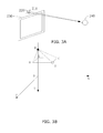
- FIGS. 3A and 3B are schematic views illustrating human eyes tracking and distance measuring in the distance adaptive holographic displaying method based on eyeball tracking according to the first embodiment of the present disclosure.
- FIG. 4 is a schematic flowchart diagram of a distance adaptive holographic displaying method based on eyeball tracking according to a second embodiment of the present disclosure.
- FIGS. 5A and 5B are schematic views illustrating human eyes tracking and distance measuring in the distance adaptive holographic displaying method based on eyeball tracking according to the second embodiment of the present disclosure.
- FIG. 6 is a schematic flowchart diagram of a distance adaptive holographic displaying method based on eyeball tracking according to a third embodiment of the present disclosure.
- FIG. 7 is a schematic flowchart diagram of a distance adaptive holographic displaying method based on eyeball tracking according to a fourth embodiment of the present disclosure.
- FIG. 8 is a schematic structural view of a distance adaptive holographic displaying device based on eyeball tracking according to an embodiment of the present disclosure.
- FIG. 9 is a schematic structural view of a distance adaptive holographic displaying device based on eyeball tracking according to another embodiment of the present disclosure.
- FIG. 10 is a schematic view illustrating the change of coordinates of positions of human eyes in the distance adaptive holographic displaying method based on eyeball tracking of the present disclosure.
- the device of the present disclosure is a device capable of adjusting viewpoints of a holographic three-dimensional display.
- devices of a same version may be used by different groups of different ages, a same group of different ages, and a same group of a same age. Because distances between the two eyes of these groups of people are usually different and viewing positions of these groups of people are also different, the imaging size of the object on the eyes of these groups of people varies and the region of the object covered by the sight of these groups of people also varies. For example, referring to FIG. 1 , FIG.
- FIG. 1 is a schematic view illustrating the principle that different distances between human eyes and a displaying screen will result in different viewing angles and different regions of the object covered by the sight of the eyes, in a distance adaptive holographic displaying method based on eyeball tracking according to a first embodiment of the present disclosure.
- the region of the object covered by the sight of the user is an area facing the user between a tangency point 121 from the center of a left eye to a left side of the object and a tangency point 120 from the center of a right eye to a right side of the object; at a position b that is at a same distance from the displaying screen as the position a but at a different angle, the user of which the interval between eyes is L observes the same object, and at this point, the region of the object covered by the sight of the user is an area facing the user between a tangency point 111 from the center of the left eye to the left side of the object and a tangency point 110 from the center of the right eye to the right side of the object; and at a position c farther from the displaying screen than the position a, the user of which the interval between eyes is L observes the same object, and at this point, the region of the
- FIG. 2 is a schematic flowchart diagram of the distance adaptive holographic displaying method based on eyeball tracking according to the first embodiment of the present disclosure.
- FIGS. 3A and 3B are schematic views illustrating human eyes tracking and distance measuring in the distance adaptive holographic displaying method based on eyeball tracking according to the first embodiment of the present disclosure. The method comprises the following steps:
- S 101 detecting a human face of a user and acquiring positions of eyes of the user, wherein the positions of the eyes of the user comprise a distance between the eyes and a displaying screen.
- a three-dimensional standard coordinate system is established by taking the center of the displaying screen as an origin, with the xy coordinate plane being parallel to the displaying screen, the positive x-axis direction being horizontal and directed towards the right, the positive y-axis direction being vertical to the x-axis and directed downwards, and the positive z-axis direction being directed towards the direction of the human eyes.
- the space coordinate system may also be established by taking other positions (e.g., a lower left corner or an upper left corner of the displaying screen) as the origin and other directions as the positive directions. For example, in FIG.
- a human face tracking camera 210 and a distance meter 220 are mounted on a display 230 or at positions near the displaying screen (e.g., on a host machine or a desktop). It is assumed that in this embodiment, the distance meter 220 is an infrared distance meter and is located on the y-axis of the coordinate system. In this embodiment, the distance meter 220 and the camera 210 are fixedly disposed at adjacent positions with respect to each other. In this way, when the camera 210 moves or remains still in response to the change in the viewing position of the user, the distance meter 220 can be driven to rotate simultaneously so as to make it convenient for the distance meter 220 to find the positions of the human eyes rapidly.
- the distance meter 220 may also not rotate.
- the distance meter 220 and the camera 210 may also be disposed separately, and the infrared distance meter used in this embodiment may also be replaced by other devices having similar functions.
- the face recognition technology may be adopted to detect a human face of the user and acquire the positions of the eyes of the user firstly, then the positions can be transformed into corresponding coordinates according to the established coordinate system, and the distance meter 220 is activated to measure a distance between the human eyes and the distance meter 220 and an angle of an optical axis of the infrared distance meter with respect to a plane of the displaying screen. As shown in FIG.
- a point Q represents the infrared distance meter 220
- a point A represents a human eye
- a coordinate of the point A in the xy plane of the coordinate system is acquired according to data obtained by the camera 210 and the coordinate system.
- a point B represents the projection of the human eye A in the yz plane
- a point C represents the projection of the human eye A in the xy plane.
- a distance QA between the human eye and the infrared distance meter 220 and an angle ⁇ AQC included between the optical axis QA of the infrared distance meter 220 and a plane (xy plane) of the displaying screen are measured by the infrared distance meter 220 .
- a triangle AQC formed by coordinates of the point A, the point Q (i.e., the infrared distance meter) and the point C is a right triangle.
- the coordinates of the eyes are (x L1 ,y L1 ), and (x R1 ,y R1 ), (x L2 ,y L2 ) and (x R2 ,y R2 ), . . .
- ⁇ n can be calculated according to the coordinate values corresponding to the eyeballs and the distances between the eyeballs when the eyes are moving. Referring to FIG. 10 , generally when the user is watching the displaying screen, the line connecting a midpoint between the both human eyes to the viewpoint on the displaying screen is substantially perpendicular to the line connecting the both human eyes. According to the nature of the right triangle, the angle ⁇ can be calculated by the following formula:
- the objective of this step may also be achieved in other ways to acquire the distance between the human eyes and the displaying screen 230 , e.g., by directly taking the distance between the infrared distance meter and the eyes as the distance Z between the eyes and the displaying screen 230 , or by calculating the distance Z between the eyes and the displaying screen 230 through use of the coordinates of the distance meter and the eyes in the established coordinate system according to the nature of the right triangle.
- S 102 adjusting the size of an object in a holographic scene along a z-axis direction in the holographic three-dimensional display according to the distance, adjusting viewpoints of different individual holographic three-dimensional images that need to be projected into a left eye and a right eye of the eyes according to the size of the object in the holographic scene along the z-axis direction, and displaying the viewpoints in the displaying screen.
- FIG. 1 is a schematic view illustrating the principle that different distances between human eyes and a displaying screen will result in different viewing angles and different regions of the object covered by the sight of the eyes, in an individual holographic three-dimensional displaying method according to a first embodiment of the present disclosure.
- the region of the object covered by the sight of the user is an area facing the user between a tangency point 131 from the center of the left eye to the left side of the object and a tangency point 130 from the center of the right eye to the right side of the object.
- the region of the object covered by the sight of the eyes of the user at the position c is larger than the region of the object covered by the sight of the eyes of the user at the position a.
- the size of an object in a holographic scene along a z-axis direction in the holographic three-dimensional display and the region of the object that can be covered by the sight of the human eyes are adjusted according to the distance between the human eyes and the displaying screen acquired in the step S 101 . For example, referring to FIG.
- the viewpoints of different individual holographic three-dimensional images that need to be projected into a left eye and a right eye of the eyes are adjusted according to the size of the object in the holographic scene along the z-axis direction and the region of the object that can be covered by the sight of the human eyes, and the viewpoints are displayed in the displaying screen.
- a dynamic grating in the display is controlled according to the viewpoints of different individual holographic three-dimensional images of the left eye and the right eye of the eyes acquired in the step S 102 so that positions of light and dark strips of the grating change adaptively. That is, the emergent direction of the light emitted by the displaying screen is adjusted to the direction of the left eye and the right eye of the eyes so that the different individual holographic three-dimensional images of the left eye and the right eye are imaged into the left eye and the right eye respectively through the dynamic grating.
- S 104 tracking the change of the positions of the eyes, and repeating the aforesaid steps to dynamically acquire the different individual holographic three-dimensional images of the left eye and the right eye so that, when the eyes are moving, the left eye and the right eye can always acquire individual holographic three-dimensional images having the correct viewpoints of the holographic three-dimensional display and of the size of the object in the holographic scene along the z-axis direction.
- FIG. 10 is a schematic view illustrating the change of coordinates of positions of human eyes in the individual holographic three-dimensional displaying method of the present disclosure.
- the individual holographic three-dimensional images of the size of the object in the holographic scene along the z-axis direction are adjusted according to the different individual holographic three-dimensional images of the left eye and right eye and the content of the object in the holographic scene that are acquired in the steps S 101 to S 103 .
- the steps S 101 to S 103 are repeated to dynamically acquire the different individual holographic three-dimensional images of the left eye and the right eye so that, when the eyes are moving, the left eye and the right eye can always acquire individual holographic three-dimensional images having the correct viewpoints of the holographic three-dimensional display and of the size of the object in the holographic scene along the z-axis direction.
- the displaying screen can adapt to users of different ages and groups having different intervals between eyes.
- the distance meter when the camera tracks the change of the positions of the human eyes, the distance meter will be driven to move together so that the distance between the eyes and the displaying screen can be calculated according to the change of the positions dynamically measured by the distance meter and the angle included between the distance meter and the displaying screen.
- the viewpoints of the holographic three-dimensional display are acquired and the size of the object in the holographic scene along the z-axis direction is adjusted in real time according to the change of the data.
- the displaying screen can adapt to users of different groups at different distances, thereby improving user experiences.
- FIG. 4 is a schematic flowchart diagram of a distance adaptive holographic displaying method based on eyeball tracking according to a second embodiment of the present disclosure. The method comprises the following steps of:
- S 301 detecting a human face of a user and acquiring positions of eyes of the user, wherein the positions of the eyes of the user comprise a distance between the eyes and a displaying screen.
- FIGS. 5A and 5B are schematic views illustrating eyes tracking and distance measuring in the distance adaptive holographic displaying method based on eyeball tracking according to the second embodiment of the present disclosure.
- a human face tracking camera 410 and a distance meter 420 are mounted on a display 430 or a host machine separately.
- the human face tracking camera 410 and the distance meter 420 are disposed symmetrically with respect to the y-axis so that when the human face tracking camera 410 tracks and captures a human face, the distance meter 420 can also locate the human eyes rapidly according to the symmetrical relationships.
- the human face tracking camera 410 and the distance meter 420 may also be disposed asymmetrically.
- the following positions of the eyes in the coordinate system are acquired according to data obtained by detecting the human face by the human face tracking camera 410 and the space coordinate system: (x L1 , y L1 ) and (x R1 ,y R1 ), (x L2 ,y L2 ) and (x R2 ,y R2 ), . . . , (x Ln ,y Ln ) and (x Rn ,y Rn ), where L represents the left eye, R represents the right eye, and n represents that the eyes move from position 1 to position n. Then, the coordinate of the distance meter 420 is adjusted so as to measure the distance between the human eyes and the distance meter 420 .
- the distance Z between the human eyes and the displaying screen is calculated according to the nature of the right triangle as follows:
- the line connecting the center of the face of the user to the center of the displaying screen is parallel to the z-axis of the coordinate system; and when the user moves at different positions, the distance between the infrared distance meter and the eyes can be taken directly as the distance Z between the eyes and the displaying screen.
- S 302 determining whether the distance is smaller than a first threshold value, and if the distance is smaller than the first threshold value, then the distance is getting smaller, and the size of the object in the holographic scene along the z-axis direction in the holographic three-dimensional display will not be enlarged; and determining whether the distance is larger than a second threshold value, and if the distance is larger than the second threshold value, then the distance is getting larger, and the size of the object in the holographic scene along the z-axis direction in the holographic three-dimensional display will not be reduced.
- Adjusting the size of an object in a holographic scene along a z-axis direction in the holographic three-dimensional display according to the distance further comprises adjusting the content of the object in the holographic scene in the holographic three-dimensional display, wherein the content of the object in the holographic scene is the appearance content of the object within the region of the object that can be covered by the sight of the both human eyes.
- a step is executed to determine whether the distance between the eyes and the displaying screen is smaller than a first threshold value, and if the distance is smaller than the first threshold value, then the distance is getting smaller, and the size of the object in the holographic scene along the z-axis direction in the holographic three-dimensional display will not be enlarged; and to determine whether the distance is larger than a second threshold value, and if the distance is larger than the second threshold value, then the distance is getting larger, and the size of the object in the holographic scene along the z-axis direction in the holographic three-dimensional display will not be reduced.
- the first threshold value is the minimum distance within the optimal viewing range
- the second threshold value is the maximum distance within the optimal viewing range.
- S 303 determining whether the distance is getting larger or smaller; and if the distance is getting larger, reducing the size of the object in the holographic scene along the z-axis direction in the holographic three-dimensional display, and meanwhile, enlarging the region of the object that can be covered by the sight of the both human eyes so as to obtain the second content of the object in the holographic scene in the adjusted holographic three-dimensional display; and otherwise, enlarging the size of the object in the holographic scene along the z-axis direction in the holographic three-dimensional display, and meanwhile, reducing the region of the object that can be covered by the sight of the both human eyes so as to obtain the content of the object in the holographic scene in the adjusted holographic three-dimensional display.
- the distance between the user and the displaying screen is within the preset optimal viewing range, it is determined whether the distance is getting larger or smaller. If the distance is getting larger, then the size of the object in the holographic scene along the z-axis direction in the holographic three-dimensional display is reduced; and otherwise, the size of the object in the holographic scene along the z-axis direction in the holographic three-dimensional display is enlarged.
- Adjusting the size of an object in a holographic scene along a z-axis direction in the holographic three-dimensional display according to the viewing distance of the user further comprises adjusting the content of the object in the holographic scene in the holographic three-dimensional display, wherein the content of the object in the holographic scene is the appearance content of the object within the region of the object that can be covered by the sight of the both human eyes.
- the content of the object in the holographic scene is the appearance content of the object within the region of the object that can be covered by the sight of the both human eyes.
- the region of the object covered by the sight of the user is an area facing the user between a tangency point 121 from the center of the left eye to the left side of the object and a tangency point 120 from the center of the right eye to the right side of the object; and at the position c farther from the displaying screen than the position a, the user of which the interval between eyes is L observes the same object, and at this point, the region of the object covered by the sight of the user is an area facing the user between a tangency point 131 from the center of the left eye to the left side of the object and a tangency point 130 from the center of the right eye to the right side of the object.
- the region of the object covered by the sight of the human eyes at the position c is larger than the region of the object covered by the sight of the human eyes at the position a, and the image of the object on the eyes at the position c is smaller than the image of the object on the eyes at the position a.
- the steps S 304 and S 305 are similar to the steps S 102 and S 103 in the aforesaid first embodiment and thus will not be further described herein.
- the viewpoints of different individual holographic three-dimensional images that need to be projected into a left eye and a right eye of the eyes are adjusted according to the size of the object in the holographic scene along the z-axis direction and the content of the object in the holographic scene acquired according to the steps S 301 to S 303 , and the viewpoints are displayed in the displaying screen.
- the content of the object in the holographic scene is the content of the object covered by the sight of the both human eyes, and for this, reference may be made to FIG. 1 and the description thereof, so this will not be further described herein.
- the size of the object in the holographic scene along the z-axis direction is enlarged and the region of the object in the holographic scene in the holographic three-dimensional display that can be covered by the sight of the human eyes is reduced adaptively, e.g., an object that is in the front of the holographic scene is enlarged, the enlarged object in the front blocks the sight of the content at the back, and the region of the object in the holographic scene in the holographic three-dimensional display that can be covered by the sight of the human eyes is reduced.
- the size of the object in the holographic scene along the z-axis direction is reduced and the region of the object in the holographic scene in the holographic three-dimensional display that can be covered by the sight of the human eyes is enlarged adaptively, e.g., the object that is in the front of the holographic scene is reduced more rapidly than the object at the back of the holographic scene, then the blocked content will show up again, and the region of the object in the holographic scene in the holographic three-dimensional display that can be covered by the sight of the human eyes is enlarged.
- S 306 tracking the change of the positions of the eyes, and repeating the aforesaid steps to dynamically acquire the different individual holographic three-dimensional images of the left eye and the right eye so that, when the eyes are moving, the left eye and the right eye can always acquire individual holographic three-dimensional images having the correct viewpoints of the holographic three-dimensional display and of the size of the object in the holographic scene along the z-axis direction.
- the camera tracks the change of the positions of the eyes in real time, and the aforesaid steps are repeated to dynamically acquire the different individual holographic three-dimensional images of the left eye and the right eye so that, when the eyes are moving, the left eye and the right eye can always acquire individual holographic three-dimensional images having the correct viewpoints of the holographic three-dimensional display and of the size of the object in the holographic scene along the z-axis direction.
- the distance between the human eyes and the displaying screen is calculated according to the coordinates of the distance meter and the eyes, or the distance between the distance meter and the eyes is directly taken as the distance Z between the human eyes and the displaying screen.
- the size of the object in the holographic scene along the z-axis direction in the holographic three-dimensional display is reduced if the distance is getting larger; and otherwise, the size of the object in the holographic scene along the z-axis direction in the holographic three-dimensional display is enlarged.
- the content of the object in the holographic scene is adjusted and the correct viewpoints of the holographic three-dimensional display is acquired so as to provide optimal visual effect to different groups of people.
- FIG. 6 is a schematic flowchart diagram of a distance adaptive holographic displaying method based on eyeball tracking according to a third embodiment of the present disclosure.
- the present disclosure provides an individual holographic three-dimensional displaying method which comprises the following steps of:
- S 501 detecting a human face of a user and acquiring positions of eyes of the user, wherein the positions of the eyes of the user comprise a distance between the eyes and a displaying screen.
- S 502 determining whether the distance is smaller than a first threshold value, and if the distance is smaller than the first threshold value, then the distance is getting smaller, and the size of the object in the holographic scene along the z-axis direction in the holographic three-dimensional display will not be enlarged; and determining whether the distance is larger than a second threshold value, and if the distance is larger than the second threshold value, then the distance is getting larger, and the size of the object in the holographic scene along the z-axis direction in the holographic three-dimensional display will not be reduced.
- S 503 determining whether the distance is getting larger or smaller; and if the distance is getting larger, reducing the size of the object in the holographic scene along the z-axis direction in the holographic three-dimensional display, and meanwhile, enlarging the region of the object that can be covered by the sight of the both human eyes so as to obtain the second content of the object in the holographic scene in the adjusted holographic three-dimensional display; and otherwise, enlarging the size of the object in the holographic scene along the z-axis direction in the holographic three-dimensional display, and meanwhile, reducing the region of the object that can be covered by the sight of the both human eyes so as to obtain the content of the object in the holographic scene in the adjusted holographic three-dimensional display.
- S 506 tracking the change of the positions of the eyes, and repeating the aforesaid steps to dynamically acquire the different individual holographic three-dimensional images of the left eye and the right eye so that, when the eyes are moving, the left eye and the right eye can always acquire individual holographic three-dimensional images having the correct viewpoints of the holographic three-dimensional display and of the size of the object in the holographic scene along the z-axis direction.
- the steps S 501 to S 506 are similar to the steps S 301 to S 306 in the aforesaid first embodiment, and the specific implementation of the step S 501 may be similar to that of the step S 101 in the first embodiment and thus will not be further described herein.
- different individual holographic sounds that need to be projected into a left ear and a right ear of ears are acquired according to the size of the object in the holographic scene along the z-axis direction, and different individual holographic sounds corresponding to the left ear and the right ear are output respectively.
- the sound at a side of the displaying screen that is closer to the user is amplified, while the sound at the other side of the displaying screen that is far away from the user is reduced.
- the right channel volume is amplified and the left channel volume is reduced; when the user is at the left side of the displaying screen, the left channel volume is amplified and the right channel volume is reduced; and when the user is at the center but away from the displaying screen, the left and the right channel volumes are reduced simultaneously.
- the size of the object in the holographic scene along the z-axis direction and the region of the object in the holographic scene in the holographic three-dimensional display that can be covered by the sight of the human eyes are adjusted according to the distance between the eyes and the displaying screen, and different individual holographic sounds corresponding to the left ear and the right ear are output respectively. This makes the effect realistic and improves user experiences.
- FIG. 7 is a schematic flowchart diagram of a distance adaptive holographic displaying method based on eyeball tracking according to a fourth embodiment of the present disclosure.
- the present disclosure provides an individual holographic three-dimensional displaying method which comprises the following steps of:
- S 601 activating a tracking camera to detect a human face of a user.
- the tracking camera is activated to detect the human face of the user so as to preliminarily determine the position of the user.
- the infrared distance meter is activated either simultaneously or not so as to acquire the distance between the eyes and the distance meter.
- a coordinate system is established in a way similar to that of the first embodiment and thus will not be further described herein.
- the human face is detected to find features of the human eyes so as to acquire the positions of the human eyes.
- the distance between the eyes and the distance meter acquired in the step S 602 the distance Z between the eyes and the displaying screen is obtained.
- the distance Z between the user and the displaying screen is acquired according to the step S 604 , and the size of the object in the holographic scene along the z-axis direction in the holographic three-dimensional display is adjusted according to the distance Z.
- the change of the distance Z is determined so that, when the viewing distance is getting larger, the size of the object in the holographic scene along the z-axis direction in the holographic three-dimensional display is reduced; and otherwise, the size of the object in the holographic scene along the z-axis direction in the holographic three-dimensional display is enlarged.
- the viewpoints of different individual holographic three-dimensional images that need to be projected into a left eye and a right eye of the eyes are adjusted according to the size of the object in the holographic scene along the z-axis direction and are displayed in the displaying screen.
- S 606 tracking the change of the positions of the eyes, and repeating the aforesaid steps to dynamically acquire the different individual holographic three-dimensional images of the left eye and the right eye so that, when the eyes are moving, the left eye and the right eye can always acquire individual holographic three-dimensional images having the correct viewpoints of the holographic three-dimensional display and of the size of the object in the holographic scene along the z-axis direction.
- FIG. 8 is a schematic structural view of a distance adaptive holographic displaying device based on eyeball tracking according to an embodiment of the present disclosure.
- the present disclosure provides a distance adaptive holographic displaying device based on eyeball tracking, which comprises a position acquiring module 710 , a displaying module 720 and an adjusting module 730 .
- the displaying module 720 is connected to the position acquiring module 710 and the adjusting module 730 respectively.
- the position acquiring module 710 is configured to detect a human face of a user and acquire positions of eyes of the user, wherein the positions of the eyes of the user comprise a distance between the eyes and a displaying screen.
- the displaying module 720 is configured to adjust the size of an object in a holographic scene along a z-axis direction in the holographic three-dimensional display according to the distance acquired by the position acquiring module 710 , to adjust viewpoints of different individual holographic three-dimensional images that need to be projected into a left eye and a right eye of the eyes according to the size of the object in the holographic scene along the z-axis direction, and to display the viewpoints in the displaying screen.
- viewpoints of different individual holographic three-dimensional images that need to be projected into a left eye and a right eye of the eyes according to the size of the object in the holographic scene along the z-axis direction
- viewpoints in the displaying screen For specific adjustment operations at different positions, reference may be made to descriptions of FIG. 10 and these will not be further described herein.
- the adjusting module 730 is configured to adjust an emergent direction of the light emitted by the displaying screen to the direction of the left eye and the right eye of the eyes so that the different individual holographic three-dimensional images of the left eye and the right eye are imaged into the left eye and the right eye respectively.
- the position acquiring module 710 is further configured to track the positions of the eyes, and the displaying module 720 adjusts the different individual holographic three-dimensional images of the left eye and the right eye dynamically so that, when the eyes are moving, the left eye and the right eye can always acquire individual holographic three-dimensional images having the correct viewpoints of the holographic three-dimensional display and of the size of the object in the holographic scene along the z-axis direction by means of the adjusting module 730 .
- FIG. 9 is a schematic structural view of a distance adaptive holographic displaying device based on eyeball tracking according to another embodiment of the present disclosure.
- the present disclosure provides a distance adaptive holographic displaying device based on eyeball tracking, which comprises a position acquiring module 810 , a displaying module 820 , an adjusting module 830 and a sound adjusting module 840 .
- the position acquiring module 810 further comprises a calculating unit 811 , an image capturing unit 812 and a distance measuring unit 813 .
- the displaying module 820 comprises a first determining unit 821 , a second determining unit 822 , a displaying unit 823 and an adjusting unit 824 .
- the calculating unit 811 is connected to the image capturing unit 812 , the distance measuring unit 813 , the adjusting module 830 and the first determining unit 821 respectively.
- the first determining module 821 is further connected to the second determining unit 822 , the sound adjusting module 840 and the displaying unit 823 , and the displaying module 820 is further connected to the adjusting module 830 .
- the image capturing unit 812 is configured to detect a human face of a user
- the distance measuring unit 813 is configured to measure the distance between the human eyes and the distance measuring unit 813 and transmit the measured data to the calculating unit 811 so as to calculate the position of the human eyes.
- the calculating unit 811 is configured to acquire, according to the data obtained by detecting the human face by the image capturing unit 812 , the following coordinate values corresponding to the eyeballs of the eyes: (x L1 ,y L1 ) and (x R1 ,y R1 ), (x L2 ,y L2 ) and (x R2 ,y R2 ), . . .
- the coordinate system can be established in the same way as that of the individual holographic three-dimensional displaying method according to the first embodiment of the present disclosure, and thus will not be further described herein.
- the displaying module 820 is configured to adjust the size of an object in a holographic scene along a z-axis direction in the holographic three-dimensional display according to the distance Z acquired by the position acquiring module 810 , to adjust viewpoints of different individual holographic three-dimensional images that need to be projected into a left eye and a right eye of the eyes according to the size of the object in the holographic scene along the z-axis direction, and to display the viewpoints in the displaying screen.
- viewpoints of different individual holographic three-dimensional images that need to be projected into a left eye and a right eye of the eyes according to the size of the object in the holographic scene along the z-axis direction
- viewpoints in the displaying screen For specific adjustment operations at different positions, reference may be made to descriptions of FIG. 10 and these will not be further described herein.
- the adjusting module 830 is configured to adjust an emergent direction of the light emitted by the displaying screen to the direction of the left eye and the right eye of the eyes so that the different individual holographic three-dimensional images of the left eye and the right eye are imaged into the left eye and the right eye respectively.
- the first determining unit 821 is configured to determine whether the distance Z between the eyes and the displaying screen is getting larger or smaller; if the distance Z between the eyes and the displaying screen is getting larger, then the adjusting unit 824 is controlled to reduce the size of the object in the holographic scene along the z-axis direction in the holographic three-dimensional display; and otherwise, the adjusting unit 824 is controlled to enlarge the size of the object in the holographic scene along the z-axis direction in the holographic three-dimensional display.
- the second determining unit 822 is configured to determine whether the distance Z between the eyes and the displaying screen is smaller than a first threshold value, and if the distance Z between the eyes and the displaying screen is smaller than the first threshold value, then the distance is getting smaller, and the adjusting unit 824 is controlled not to enlarge the size of the object in the holographic scene along the z-axis direction in the holographic three-dimensional display; and the second determining unit 822 is further configured to determine whether the distance Z between the eyes and the displaying screen is larger than a second threshold value, and if the distance is larger than the second threshold value, then the distance is getting larger, and the adjusting unit 824 is controlled not to reduce the size of the object in the holographic scene along the z-axis direction in the holographic three-dimensional display.
- the adjusting unit 824 is configured to adjust the size of an object in a holographic scene along a z-axis direction in the holographic three-dimensional display and the content of the object in the holographic scene in the holographic three-dimensional display according to the determination result of the first determining module 821 , wherein the content of the object in the holographic scene is the appearance content of the object within the region of the object that can be covered by the sight of the both human eyes.
- the position acquiring module 810 is further configured to track the positions of the eyes, and the displaying module 820 adjusts the different individual holographic three-dimensional images of the left eye and the right eye dynamically so that, when the eyes are moving, the left eye and the right eye can always acquire individual holographic three-dimensional images having the correct viewpoints of the holographic three-dimensional display and of the size of the object in the holographic scene along the z-axis direction by means of the adjusting module 830 .
- the sound adjusting module 840 is configured to adjust different individual holographic sounds that need to be projected into a left ear and a right ear of ears according to the viewpoints of the holographic three-dimensional display and the size of the object in the holographic scene along the z-axis direction, and to output the different individual holographic sounds corresponding to the left ear and the right ear respectively.
- the sound at a side of the displaying screen that is closer to the user is amplified, while the sound at the other side of the displaying screen that is far away from the user is reduced.
Applications Claiming Priority (3)
| Application Number | Priority Date | Filing Date | Title |
|---|---|---|---|
| CN201410712422.1 | 2014-11-28 | ||
| CN201410712422 | 2014-11-28 | ||
| CN201410712422.1A CN104618705B (zh) | 2014-11-28 | 2014-11-28 | 基于眼球追踪的不同距离自适应全息显示方法及设备 |
Publications (2)
| Publication Number | Publication Date |
|---|---|
| US20160154458A1 US20160154458A1 (en) | 2016-06-02 |
| US10101807B2 true US10101807B2 (en) | 2018-10-16 |
Family
ID=53152962
Family Applications (1)
| Application Number | Title | Priority Date | Filing Date |
|---|---|---|---|
| US14/953,342 Active 2036-05-25 US10101807B2 (en) | 2014-11-28 | 2015-11-28 | Distance adaptive holographic displaying method and device based on eyeball tracking |
Country Status (5)
| Country | Link |
|---|---|
| US (1) | US10101807B2 (fr) |
| EP (1) | EP3026905A1 (fr) |
| JP (1) | JP2016110123A (fr) |
| KR (1) | KR101730737B1 (fr) |
| CN (1) | CN104618705B (fr) |
Families Citing this family (28)
| Publication number | Priority date | Publication date | Assignee | Title |
|---|---|---|---|---|
| CN105592306A (zh) * | 2015-12-18 | 2016-05-18 | 深圳前海达闼云端智能科技有限公司 | 一种三维立体显示处理方法和装置 |
| CN114554177A (zh) * | 2016-05-19 | 2022-05-27 | 瑞尔D斯帕克有限责任公司 | 广角成像定向背光源 |
| CN107728790B (zh) * | 2016-07-08 | 2021-03-09 | Oppo广东移动通信有限公司 | 一种屏幕显示方法、装置及移动终端、存储介质 |
| CN106162129B (zh) * | 2016-08-31 | 2019-05-10 | 蒋欣飏 | 一种投影装置 |
| CN107343161A (zh) * | 2016-12-30 | 2017-11-10 | 苏州四海观览智能仪器有限公司 | 光学仪器 |
| CN106773588B (zh) * | 2017-01-03 | 2019-07-23 | 京东方科技集团股份有限公司 | 一种全息显示装置及其控制方法 |
| CN107065184A (zh) * | 2017-03-29 | 2017-08-18 | 核桃智能科技(常州)有限公司 | 一种具有可调整目镜的头戴显示系统组件 |
| TWI622806B (zh) * | 2017-04-11 | 2018-05-01 | 宏碁股份有限公司 | 虛擬實境顯示裝置 |
| US10574662B2 (en) * | 2017-06-20 | 2020-02-25 | Bank Of America Corporation | System for authentication of a user based on multi-factor passively acquired data |
| CN107797664B (zh) * | 2017-10-27 | 2021-05-07 | Oppo广东移动通信有限公司 | 内容显示方法、装置及电子装置 |
| EP3750151A4 (fr) * | 2018-02-08 | 2021-12-29 | Innovations Mindtrick Inc. | Dispositif d'affichage d'image stéréoscopique réglé par le spectateur |
| US20190303177A1 (en) * | 2018-03-29 | 2019-10-03 | Microsoft Technology Licensing, Llc | Adaptive User Interface Based On Detection Of User Positions |
| US11188154B2 (en) * | 2018-05-30 | 2021-11-30 | International Business Machines Corporation | Context dependent projection of holographic objects |
| US10928775B2 (en) | 2018-07-17 | 2021-02-23 | International Business Machines Corporation | 3D holographic display and holographic object formation |
| CN108881893A (zh) * | 2018-07-23 | 2018-11-23 | 上海玮舟微电子科技有限公司 | 基于人眼跟踪的裸眼3d显示方法、装置、设备和介质 |
| CN109144250B (zh) * | 2018-07-24 | 2021-12-21 | 北京七鑫易维信息技术有限公司 | 一种位置调节的方法、装置、设备及存储介质 |
| CN109636895B (zh) * | 2018-10-31 | 2023-11-17 | 北京航天晨信科技有限责任公司 | 一种全息显示方法和电子沙盘装置 |
| CN109597555B (zh) * | 2018-12-06 | 2022-09-06 | 佛山市原子文化传播有限公司 | 一种根据场景及对象调整显示方式的方法及系统 |
| CN109819402B (zh) * | 2019-01-08 | 2021-07-06 | 李超豪 | 用于监督改善学习习惯的方法及其系统 |
| US11330251B2 (en) * | 2019-01-16 | 2022-05-10 | International Business Machines Corporation | Defining a holographic object allowance area and movement path |
| CN111751987B (zh) * | 2019-03-29 | 2023-04-14 | 托比股份公司 | 全息眼睛成像设备 |
| CN110124305B (zh) * | 2019-05-15 | 2023-05-12 | 网易(杭州)网络有限公司 | 虚拟场景调整方法、装置、存储介质与移动终端 |
| CN110706268B (zh) * | 2019-11-14 | 2022-12-27 | 维沃移动通信有限公司 | 一种距离调整方法及电子设备 |
| CN110913074B (zh) * | 2019-11-28 | 2022-04-08 | 北京小米移动软件有限公司 | 视距调整方法及装置、移动设备、存储介质 |
| US11190754B2 (en) * | 2020-01-22 | 2021-11-30 | 3D Media Ltd. | 3D display device having a processor for correcting pseudostereoscopic effect |
| CN111949124B (zh) * | 2020-07-02 | 2023-09-01 | 广东工业大学 | 一种基于视觉跟踪的自适应显示器定位方法 |
| CN112040316B (zh) * | 2020-08-26 | 2022-05-20 | 深圳创维-Rgb电子有限公司 | 视频图像显示方法、装置、多媒体设备以及存储介质 |
| CN112255903A (zh) * | 2020-10-15 | 2021-01-22 | 启迪虚拟现实(南京)科技发展有限公司 | 全息三维空间裸眼3d舞台呈现装置 |
Citations (13)
| Publication number | Priority date | Publication date | Assignee | Title |
|---|---|---|---|---|
| US5579026A (en) | 1993-05-14 | 1996-11-26 | Olympus Optical Co., Ltd. | Image display apparatus of head mounted type |
| US20100149313A1 (en) | 2007-05-21 | 2010-06-17 | Bo Kroll | Holographic Reconstruction system with a Tracking Device for the Reconstruction |
| US20100253766A1 (en) | 2009-04-01 | 2010-10-07 | Mann Samuel A | Stereoscopic Device |
| US20110058240A1 (en) * | 2009-03-20 | 2011-03-10 | Absolute Imaging LLC | System and Method for Autostereoscopic Imaging Using Holographic Optical Element |
| US20120062556A1 (en) | 2010-09-13 | 2012-03-15 | Sumihiko Yamamoto | Three-dimensional image display apparatus, three-dimensional image processor, three-dimensional image display method, and computer program product |
| CN103018915A (zh) | 2012-12-10 | 2013-04-03 | Tcl集团股份有限公司 | 一种基于人眼追踪的3d集成成像显示方法及集成成像3d显示器 |
| WO2013107467A1 (fr) | 2012-01-17 | 2013-07-25 | Sony Ericsson Mobile Communications Ab | Équipement électronique portatif et procédé de commande d'un affichage auto-stéréoscopique |
| US20130235073A1 (en) * | 2012-03-09 | 2013-09-12 | International Business Machines Corporation | Automatically modifying presentation of mobile-device content |
| US20140306954A1 (en) | 2013-04-11 | 2014-10-16 | Wistron Corporation | Image display apparatus and method for displaying image |
| US20140333735A1 (en) * | 2013-05-07 | 2014-11-13 | Elwha Llc | Controllable lenticular lenslets |
| US20150055085A1 (en) * | 2013-08-22 | 2015-02-26 | Bespoke, Inc. | Method and system to create products |
| US20150138613A1 (en) * | 2013-11-06 | 2015-05-21 | Electronics And Telecommunications Research Institute | Apparatus and method for displaying pseudo-hologram image based on pupil tracking |
| US20160048018A1 (en) * | 2013-03-26 | 2016-02-18 | Lusospace, Projectos Engenharia Lda | Display device |
-
2014
- 2014-11-28 CN CN201410712422.1A patent/CN104618705B/zh active Active
-
2015
- 2015-11-27 KR KR1020150167776A patent/KR101730737B1/ko active IP Right Grant
- 2015-11-27 JP JP2015231678A patent/JP2016110123A/ja active Pending
- 2015-11-27 EP EP15196833.6A patent/EP3026905A1/fr not_active Ceased
- 2015-11-28 US US14/953,342 patent/US10101807B2/en active Active
Patent Citations (19)
| Publication number | Priority date | Publication date | Assignee | Title |
|---|---|---|---|---|
| US5579026A (en) | 1993-05-14 | 1996-11-26 | Olympus Optical Co., Ltd. | Image display apparatus of head mounted type |
| US20100149313A1 (en) | 2007-05-21 | 2010-06-17 | Bo Kroll | Holographic Reconstruction system with a Tracking Device for the Reconstruction |
| US20140168734A1 (en) * | 2009-03-20 | 2014-06-19 | Absolute Imaging LLC | System and method for autostereoscopic imaging using holographic optical element |
| US20110058240A1 (en) * | 2009-03-20 | 2011-03-10 | Absolute Imaging LLC | System and Method for Autostereoscopic Imaging Using Holographic Optical Element |
| US20100253766A1 (en) | 2009-04-01 | 2010-10-07 | Mann Samuel A | Stereoscopic Device |
| US20120062556A1 (en) | 2010-09-13 | 2012-03-15 | Sumihiko Yamamoto | Three-dimensional image display apparatus, three-dimensional image processor, three-dimensional image display method, and computer program product |
| WO2013107467A1 (fr) | 2012-01-17 | 2013-07-25 | Sony Ericsson Mobile Communications Ab | Équipement électronique portatif et procédé de commande d'un affichage auto-stéréoscopique |
| US20130235073A1 (en) * | 2012-03-09 | 2013-09-12 | International Business Machines Corporation | Automatically modifying presentation of mobile-device content |
| CN103018915A (zh) | 2012-12-10 | 2013-04-03 | Tcl集团股份有限公司 | 一种基于人眼追踪的3d集成成像显示方法及集成成像3d显示器 |
| US20160048018A1 (en) * | 2013-03-26 | 2016-02-18 | Lusospace, Projectos Engenharia Lda | Display device |
| US20140306954A1 (en) | 2013-04-11 | 2014-10-16 | Wistron Corporation | Image display apparatus and method for displaying image |
| US9013564B2 (en) * | 2013-05-07 | 2015-04-21 | Elwha Llc | Controllable lenticular lenslets |
| US20140333735A1 (en) * | 2013-05-07 | 2014-11-13 | Elwha Llc | Controllable lenticular lenslets |
| US20150055085A1 (en) * | 2013-08-22 | 2015-02-26 | Bespoke, Inc. | Method and system to create products |
| US20160062152A1 (en) * | 2013-08-22 | 2016-03-03 | Bespoke, Inc. | Method and system to create custom, user-specific eyewear |
| US9529213B2 (en) * | 2013-08-22 | 2016-12-27 | Bespoke, Inc. | Method and system to create custom, user-specific eyewear |
| US20170068121A1 (en) * | 2013-08-22 | 2017-03-09 | Bespoke, Inc. | Method and system to create custom, user-specific eyewear |
| US20170269385A1 (en) * | 2013-08-22 | 2017-09-21 | Bespoke, Inc. d/b/a/ Topology Eyewear | Method and system to create custom, user-specific eyewear |
| US20150138613A1 (en) * | 2013-11-06 | 2015-05-21 | Electronics And Telecommunications Research Institute | Apparatus and method for displaying pseudo-hologram image based on pupil tracking |
Also Published As
| Publication number | Publication date |
|---|---|
| KR101730737B1 (ko) | 2017-04-26 |
| JP2016110123A (ja) | 2016-06-20 |
| US20160154458A1 (en) | 2016-06-02 |
| EP3026905A1 (fr) | 2016-06-01 |
| CN104618705B (zh) | 2017-04-05 |
| CN104618705A (zh) | 2015-05-13 |
| KR20160065036A (ko) | 2016-06-08 |
Similar Documents
| Publication | Publication Date | Title |
|---|---|---|
| US10101807B2 (en) | Distance adaptive holographic displaying method and device based on eyeball tracking | |
| US11734867B2 (en) | Detecting physical boundaries | |
| US9785233B2 (en) | Systems and methods of eye tracking calibration | |
| KR101741335B1 (ko) | 안구추적을 기반으로 한 홀로그램 디스플레이 방법 및 홀로그램 디스플레이 장치 | |
| US10943409B2 (en) | Information processing apparatus, information processing method, and program for correcting display information drawn in a plurality of buffers | |
| CN104506836B (zh) | 基于眼球追踪的个人全息三维显示方法及设备 | |
| US11755102B2 (en) | User interface interaction paradigms for eyewear device with limited field of view | |
| US11127380B2 (en) | Content stabilization for head-mounted displays | |
| US20130181892A1 (en) | Image Adjusting | |
| CN104661012B (zh) | 个人全息三维显示方法及设备 | |
| US9160931B2 (en) | Modifying captured image based on user viewpoint | |
| US10948994B2 (en) | Gesture control method for wearable system and wearable system | |
| US11726327B2 (en) | Eyewear having unsynchronized rolling shutter cameras | |
| US20210397253A1 (en) | Gaze tracking apparatus and systems | |
| WO2018146922A1 (fr) | Dispositif de traitement d'informations, procédé de traitement d'informations et programme | |
| EP3402410B1 (fr) | Système de détection | |
| WO2016051431A1 (fr) | Dispositif d'entrée/sortie, programme d'entrée/sortie et procédé d'entrée/sortie | |
| TW201518994A (zh) | 液晶顯示器顯示視角的調整方法、裝置和系統 | |
| US20120026309A1 (en) | Media display system and adjustment method therefor | |
| US20200159339A1 (en) | Desktop spatial stereoscopic interaction system | |
| US20180101226A1 (en) | Information processing apparatus | |
| GB2598953A (en) | Head mounted display |
Legal Events
| Date | Code | Title | Description |
|---|---|---|---|
| AS | Assignment |
Owner name: SHENZHEN ESTAR TECHNOLOGY GROUP CO., LTD., CHINA Free format text: ASSIGNMENT OF ASSIGNORS INTEREST;ASSIGNORS:LIU, MEIHONG;GAO, WEI;XU, WANLIANG;REEL/FRAME:037161/0562 Effective date: 20151126 |
|
| AS | Assignment |
Owner name: SHENZHEN MAGIC EYE TECHNOLOGY CO., LTD., CHINA Free format text: ASSIGNMENT OF ASSIGNORS INTEREST;ASSIGNOR:SHENZHEN ESTAR TECHNOLOGY GROUP CO., LTD.;REEL/FRAME:040995/0279 Effective date: 20161125 |
|
| STCF | Information on status: patent grant |
Free format text: PATENTED CASE |
|
| AS | Assignment |
Owner name: SHENZHEN SMART SUPERV CO., LTD., CHINA Free format text: ASSIGNMENT OF ASSIGNORS INTEREST;ASSIGNOR:SHENZHEN MAGIC EYE TECHNOLOGY CO., LTD.;REEL/FRAME:054022/0180 Effective date: 20201009 |
|
| MAFP | Maintenance fee payment |
Free format text: PAYMENT OF MAINTENANCE FEE, 4TH YR, SMALL ENTITY (ORIGINAL EVENT CODE: M2551); ENTITY STATUS OF PATENT OWNER: SMALL ENTITY Year of fee payment: 4 |