US10101445B2 - Power centroid radar - Google Patents
Power centroid radar Download PDFInfo
- Publication number
- US10101445B2 US10101445B2 US14/699,335 US201514699335A US10101445B2 US 10101445 B2 US10101445 B2 US 10101445B2 US 201514699335 A US201514699335 A US 201514699335A US 10101445 B2 US10101445 B2 US 10101445B2
- Authority
- US
- United States
- Prior art keywords
- scm
- radar
- antenna
- covariance matrix
- clutter
- Prior art date
- Legal status (The legal status is an assumption and is not a legal conclusion. Google has not performed a legal analysis and makes no representation as to the accuracy of the status listed.)
- Active, expires
Links
Images

Classifications
-
- G—PHYSICS
- G01—MEASURING; TESTING
- G01S—RADIO DIRECTION-FINDING; RADIO NAVIGATION; DETERMINING DISTANCE OR VELOCITY BY USE OF RADIO WAVES; LOCATING OR PRESENCE-DETECTING BY USE OF THE REFLECTION OR RERADIATION OF RADIO WAVES; ANALOGOUS ARRANGEMENTS USING OTHER WAVES
- G01S13/00—Systems using the reflection or reradiation of radio waves, e.g. radar systems; Analogous systems using reflection or reradiation of waves whose nature or wavelength is irrelevant or unspecified
- G01S13/02—Systems using reflection of radio waves, e.g. primary radar systems; Analogous systems
- G01S13/50—Systems of measurement based on relative movement of target
- G01S13/52—Discriminating between fixed and moving objects or between objects moving at different speeds
- G01S13/522—Discriminating between fixed and moving objects or between objects moving at different speeds using transmissions of interrupted pulse modulated waves
- G01S13/524—Discriminating between fixed and moving objects or between objects moving at different speeds using transmissions of interrupted pulse modulated waves based upon the phase or frequency shift resulting from movement of objects, with reference to the transmitted signals, e.g. coherent MTi
- G01S13/5244—Adaptive clutter cancellation
-
- G—PHYSICS
- G01—MEASURING; TESTING
- G01S—RADIO DIRECTION-FINDING; RADIO NAVIGATION; DETERMINING DISTANCE OR VELOCITY BY USE OF RADIO WAVES; LOCATING OR PRESENCE-DETECTING BY USE OF THE REFLECTION OR RERADIATION OF RADIO WAVES; ANALOGOUS ARRANGEMENTS USING OTHER WAVES
- G01S13/00—Systems using the reflection or reradiation of radio waves, e.g. radar systems; Analogous systems using reflection or reradiation of waves whose nature or wavelength is irrelevant or unspecified
- G01S13/02—Systems using reflection of radio waves, e.g. primary radar systems; Analogous systems
- G01S13/50—Systems of measurement based on relative movement of target
- G01S13/52—Discriminating between fixed and moving objects or between objects moving at different speeds
- G01S13/522—Discriminating between fixed and moving objects or between objects moving at different speeds using transmissions of interrupted pulse modulated waves
- G01S13/524—Discriminating between fixed and moving objects or between objects moving at different speeds using transmissions of interrupted pulse modulated waves based upon the phase or frequency shift resulting from movement of objects, with reference to the transmitted signals, e.g. coherent MTi
- G01S13/5242—Discriminating between fixed and moving objects or between objects moving at different speeds using transmissions of interrupted pulse modulated waves based upon the phase or frequency shift resulting from movement of objects, with reference to the transmitted signals, e.g. coherent MTi with means for platform motion or scan motion compensation, e.g. airborne MTI
-
- G—PHYSICS
- G01—MEASURING; TESTING
- G01S—RADIO DIRECTION-FINDING; RADIO NAVIGATION; DETERMINING DISTANCE OR VELOCITY BY USE OF RADIO WAVES; LOCATING OR PRESENCE-DETECTING BY USE OF THE REFLECTION OR RERADIATION OF RADIO WAVES; ANALOGOUS ARRANGEMENTS USING OTHER WAVES
- G01S7/00—Details of systems according to groups G01S13/00, G01S15/00, G01S17/00
- G01S7/02—Details of systems according to groups G01S13/00, G01S15/00, G01S17/00 of systems according to group G01S13/00
- G01S7/28—Details of pulse systems
- G01S7/285—Receivers
- G01S7/292—Extracting wanted echo-signals
- G01S7/2923—Extracting wanted echo-signals based on data belonging to a number of consecutive radar periods
- G01S7/2925—Extracting wanted echo-signals based on data belonging to a number of consecutive radar periods by using shape of radiation pattern
-
- G—PHYSICS
- G01—MEASURING; TESTING
- G01S—RADIO DIRECTION-FINDING; RADIO NAVIGATION; DETERMINING DISTANCE OR VELOCITY BY USE OF RADIO WAVES; LOCATING OR PRESENCE-DETECTING BY USE OF THE REFLECTION OR RERADIATION OF RADIO WAVES; ANALOGOUS ARRANGEMENTS USING OTHER WAVES
- G01S7/00—Details of systems according to groups G01S13/00, G01S15/00, G01S17/00
- G01S7/02—Details of systems according to groups G01S13/00, G01S15/00, G01S17/00 of systems according to group G01S13/00
- G01S7/28—Details of pulse systems
- G01S7/285—Receivers
- G01S7/295—Means for transforming co-ordinates or for evaluating data, e.g. using computers
-
- G—PHYSICS
- G01—MEASURING; TESTING
- G01S—RADIO DIRECTION-FINDING; RADIO NAVIGATION; DETERMINING DISTANCE OR VELOCITY BY USE OF RADIO WAVES; LOCATING OR PRESENCE-DETECTING BY USE OF THE REFLECTION OR RERADIATION OF RADIO WAVES; ANALOGOUS ARRANGEMENTS USING OTHER WAVES
- G01S7/00—Details of systems according to groups G01S13/00, G01S15/00, G01S17/00
- G01S7/02—Details of systems according to groups G01S13/00, G01S15/00, G01S17/00 of systems according to group G01S13/00
- G01S7/28—Details of pulse systems
- G01S7/285—Receivers
- G01S7/34—Gain of receiver varied automatically during pulse-recurrence period, e.g. anti-clutter gain control
Definitions
- the subject matter disclosed herein relates to an intelligent system (IS) that uses a knowledge-aided (KA) airborne moving target indicator (AMTI) radar such as found in DARPA's knowledge aided sensory signal processing expert reasoning (KASSPER).
- KA knowledge-aided
- AMTI airborne moving target indicator
- DARPA DARPA's knowledge aided sensory signal processing expert reasoning
- PC-Radar Power centroid radar
- This method uses a predetermined number of predicted clutter covariance signal values found from, for example, a specified number of possible power centroid quantization levels.
- PC KA knowledge-aided power centroid
- the intelligent system comprises a memory device containing the intelligence or prior knowledge.
- the intelligence is clutter whose knowledge facilitates the detection of a moving target.
- the clutter is available in the form of synthetic aperture radar (SAR) imagery. Since the required memory space for SAR imagery is prohibitive, it then becomes necessary to use ‘lossy’ memory space compression source coding schemes to address this problem of memory space. An improved system is therefore desired.
- SAR synthetic aperture radar
- a system for signal processing is provided that obviates the use of prior-knowledge, such as synthetic aperture radar (SAR) imagery, in time compressed signal processing (i.e. it can be knowledge unaided).
- the knowledge-unaided power centroid (PC KU ) is found by evaluating a covariance matrix R SCM for its moments m i . Because R SCM uses a sample signal, rather than SAR data, the power centroid PC KU may be found without needing SAR data.
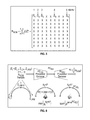
- FIG. 1 is the time dual of Information Theory's Source Coding
- FIG. 2 is block diagram of a signal decoder
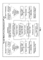
- FIG. 3 a block-diagram of a decoder with a processor-encoder that derives PC KA from range-bin measurements extracted from SAR imagery and a second processor-decoder that receives PC KA and appropriately derived values for ⁇ and ⁇ AAM to yield KA C c f ( ⁇ AAM );
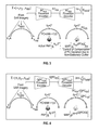
- FIG. 4 a block-diagram description for the on-line computational structure that determines PC KA then follows it by the PC quantization yielding as output Q[PC KA ];
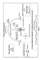
- FIG. 6 a block-diagram showing the KU C c f ( ⁇ AAM ) derivation
- FIG. 7 is a block-diagram description for the computation of QKU C c f ( ⁇ AAM );
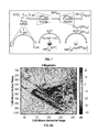
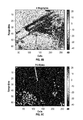
- FIG. 8A is the SAR image of the Mojave Airport in California displayed in 4 megabyte;
- FIG. 8B where each row denotes a range-bin with 256 clutter cells that will be used in our simulations;
- FIG. 8C a compressed 512 bytes
- FIG. 8D and FIG. 8E show clutter and power centroid values
- FIGS. 9A to 9G and FIG. 10A to 10G show the simulation results
- the subject matter disclosed herein relates to a system for signal processing that obviates the use of prior-knowledge, such as synthetic aperture radar (SAR) imagery in time compressed signal processing (i.e. it can be knowledge unaided).
- SAR synthetic aperture radar
- the disclosed system solves the problem of jointly compressing storage-space and computational-time associated with the evaluation of high dimensional clutter covariance matrices.
- Applications of the algorithm are found in radar system and in other fields, such as cognition problems and ratio.
- the method described here provides an alternate method for calculating a knowledge-unaided power centroid (PC KU ) that obviates the need for SARS data.
- the knowledge-unaided power centroid (PC KU ) may then be used in accordance with the teachings of U.S. Pat. Nos. 7,773,032 and 8,098,196.
- the knowledge-unaided power centroid (PC KU ) is found by evaluating a sample covariance matrix R SCM for its moments m i . Because R SCM uses a sample signal, rather than SAR data, the power centroid PC KU may be found without needing SAR data.
- Radar uses radio waves to find the range, altitude, direction, or speed of objects. Its applications are widespread such as in defense, space, commercial and medical investigations of tissue, heart and respiratory states. In demanding applications, such as in moving target indicator (MTI) radar for ground or airborne targets, its performance can be significantly degraded by interference and thermal white noise.
- the interference can be of various kinds such as clutter, jammer, range walk, channel mismatch, internal clutter motion and antenna array misalignments.
- adaptive radar systems are designed that address any changes that may occur in the operating environment. Of the aforementioned interference types, clutter, which are returns from the range-bin where a target is being investigated, is without doubt the one most difficult to adapt to.
- KU knowledge-unaided
- KA knowledge-aided
- SCM-Radar sample covariance matrix radar
- KA radar techniques of this kind were developed, for instance, under a Defense Advanced Research Projects Agency (DARPA) KA Sensory Signal Processing and Expert Reasoning (KASSPER) program.
- DRPA Defense Advanced Research Projects Agency
- KASSPER KA Sensory Signal Processing and Expert Reasoning
- the KASSPER schemes were applied to ground moving target indicator (GMTI) applications. Although some of the radar schemes could yield a superior SINR radar performance their designs were subjected to severe constraints.
- the four were: 1) a “source” uncertainty function measured by a source entropy space-metric (this metric is the Shannon's “info-source” entropy in LIT and the Boltzmann's “thermo-source” entropy in LTT); 2) a “processor” certainty function measured by a novel processor ectropy time-metric; 3) a “retainer” uncertainty function measured by a novel retainer entropy space-metric; and 4) a “mover” certainty function measured by a novel mover ectropy time-metric. Yet the nature of the LIT and LTT space/time metrics were quite different.
- LIT In the case of LIT they were time invariant, or stationary in nature, while in the LTT case they were time varying, or dynamic in nature.
- the LTT dynamic property has roots in one of the four laws of thermodynamics that drive the universe, (more specifically, the 2 nd law of thermodynamics) that states that the Boltzmann entropy (or equivalently the thermo-source entropy space-metric) increases with time for a closed system. It can be shown that similar increases occur to the remaining LTT space/time metrics with the passing of time.
- Appendix C a brief outline for LTT is given where the basic ideas are illustrated with black-hole, photon-gas and flexible-phase mediums. Moreover, for the flexible-phase medium it is shown that an entropy theory inherently emerges from LTT in a sensible and compelling manner.
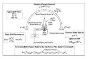
- PC-Radar emerged from Latency Theory's Processor Coding, see top of FIG. 1 , which is the time dual of Information Theory's Source Coding. While a source coder such as a predictive transform (PT) one, aims for high “bit-space compressions”, a processor coder such as a power centroid (PC) one, aims for high “bor-time compressions”, i.e., the smallest possible number of binary operator (or bor) levels from processor input to output.
- PT predictive transform
- PC power centroid
- PC-Radar a processor encoder followed by a processor decoder derives the front clutter covariance matrix (C c f ( ⁇ AAM )), that is also a function of any existing antenna array misalignment angle ⁇ AAM as noted in Section II.
- the objective of the encoder is to measure the power-centroid (PC) of the clutter emanating from the front range-bin displayed in FIG. 2 .
- PC power-centroid
- FIG. 2 This figure shows the physical antenna pattern (PAP) for a phased array antenna of a moving target indicator or MTI that is directed towards an investigated target on the front range-bin.
- PAP physical antenna pattern
- the range-bin PC location would be the same as where the PAP points.
- the “physical duality” conveyed the separation of the system design into a space-uncertainty communication problem and a time-certainty control problem
- the “mathematical duality” conveyed the appearance of identical mathematical structures in the separately designed communication/control subsystems.
- MPs Motion Processors
- LQG-Control dealt with continuous control
- MPs-Control dealt with quantized control.
- MPs-Control the certainty-based parallel structures of the Matched Processors controller was the control's certainty-based dual of communication's uncertainty-based parallel structures of Matched-Filters for bit detection.
- a remarkable result of MPs-Control was that unlike Bellman's Dynamic Programming, it did not suffer of what Bellman called “the curse of dimensionality” when referring to the exponential increase in computational burden as the process state dimension increased in value.
- the objective of the decoder is to use the measured PC to select a C c f ( ⁇ AAM ) realization from a stored set, where the elements of the set are evaluated off-line and are matched to unique range-bin PC and ⁇ AAM quantization levels.
- the best matched C c f ( ⁇ AAM ) is then used in an interference plus noise covariance (R) expression, see the bottom of FIG.
- PC-Radar Under severely taxing environmental conditions (as will be seen later in Section IV) PC-Radar yields outstanding SINR results, even if only a few quantization levels are used for the PC.
- KA For the KA case it also offers a significant implementation advantage since “radar-blind” image compression of SAR imagery is now possible.
- the power centroid is derived directly from a sample covariance matrix. This result is remarkable since with a very simple KU scheme PC-Radar approaches the SINR performance of Optimum-Radar.
- This type of interference is due to the movement of the radar platform during a coherent pulse interval (CPI).
- CPI denotes the time delay associated with the transmission of M pulses by N antenna elements of the “phased array antenna” assumed in our MTI radar model.
- the product of N and M, i.e., NM, represents the degrees of freedom (DoF) of the radar system. This number is also the assumed number of cells for the investigated range-bin displayed in FIG. 2 .
- the covariance matrix for range walk is studied in Appendix A where expressions (A.9)-(A.12) define it.
- H denotes a vector complex conjugate transposition, i.e., a Hermitian transpose. The derivation of the gain w is discussed next.
- SINR* s H R ⁇ 1 s (6)
- the covariance matrix tapers model is then used for the interference plus noise covariance matrix (R).
- the mathematical expressions defining the target steering vector (s), the antenna pattern for a uniform linear array (ULA) and the front clutter covariance matrix C c f ( ⁇ AAM ) are given next.
- the definition for the remaining covariances in the R expressions (7)-(8) are as defined in Appendix A.
- the values for these matrices are assumed to be either known or of zero value as is the case for the back clutter covariance matrix C c b ( ⁇ AAM ).
- the mathematical model for the target signal is noted.
- the MTI system is assumed to receive from the target a normalized steering vector (s).
- f c is the carrier (or operating) frequency of the radar system; 3) d is the antenna inter-element spacing; 4) ⁇ is the operating wavelength; 5) ⁇ t is the normalized ⁇ t ; 6) T r is the pulse repetition interval (PRI); 7) f r is the pulse repetition frequency (PRF); 8) v is the target radial velocity; 9) c is the speed of light; 10) f D t is the target Doppler; and 11) f D t is the normalized Doppler.
- the MTI is characterized by a uniform linear array (ULA) that yields the following analytical and normalized gain expression for an antenna pattern with NM degrees of freedom:
- 2) ⁇ i is the value of the boresight angle corresponding to the i th range-bin cell
- ⁇ t is the value of the boresight angle where the target of interest resides
- N is the number of antenna elements
- M is the number of pulses transmitted during the coherent pulse interval
- 5) NM is the number of range-bin cells which is the same as the number of degrees of freedom
- d is the antenna inter-e
- the front clutter covariance matrix (C c f ( ⁇ AAM )) is modeled according to:
- the primary goal of a PC-Radar scheme is the adaptive evaluation of the front clutter covariance matrix C c f ( ⁇ AAM ) (18) for later use in determining the interference plus noise covariance R expression (7)-(8), where it is also assumed that the remaining covariances in the expressions can be independently found.
- C c f ⁇ AAM
- R expression (7)-(8) the interference plus noise covariance
- KA PC-Radar the front clutter covariance matrix (C c f ( ⁇ AAM )) of (18) is replaced by a KA version ( KA C c f ( ⁇ AAM )) defined according to:
- FIG. 3 a block-diagram description for the computations of (27)-(29) is shown.
- the block-diagram is noted to have two major components.
- One is a processor-encoder that derives PC KA from range-bin measurements which are extracted from SAR imagery.
- the second major component is a processor-decoder that receives PC KA and appropriately derived values for ⁇ and ⁇ AAM to yield KA C c f ( ⁇ AAM ).
- this processor encoder/decoder structure is the computational-time compression dual of the source encoder/decoder structure for storage-space compression, and thus transparently displays its UC-Duality roots.
- FIG. 4 a block-diagram description for the online computational structure that determines (30) is given.
- the processor encoder for this case performs the evaluation of PC 1 according to (28) and then follows it by the PC quantization according to (31) thus yielding as output Q[PC KA ].
- the processor decoder is a fast lookup memory that stores off-line derived evaluations of (30) corresponding to allowed quantization levels for PC KA and known values for ⁇ and ⁇ AAM . It is also assumed here that appropriate quantizations of ⁇ and ⁇ AAM are available for off-line evaluations of QKA C c f ( ⁇ AAM ).
- the processor decoder selects from its memory the QKA C c f ( ⁇ AAM ) case that is matched to the received Q[PC KA ] as well as on-line determined quantizations of ⁇ and ⁇ AAM .
- storage-space savings can be achieved by increasing the computational-time burden. For instance, this occurs when quantization versions of QKA C c f ( ⁇ AAM )/ ⁇ rather than of QKA C c f ( ⁇ AAM ) are saved, with the best case of QKA C c f ( ⁇ AAM )/ ⁇ first fetched from the memory and then multiplied by the on-line evaluated ⁇ .
- the SAR imagery is used.
- R SCM on-line determined sample covariance matrix
- KA C c f ( ⁇ AAM ) the KA front clutter covariance matrix ( KA C c f ( ⁇ AAM )) of (27) is replaced by a KU version ( KU C c f ( ⁇ AAM )) defined according to:
- FIG. 6 a block-diagram description for the KU C c f ( ⁇ AAM ) derivation of (33) is shown.
- the block-diagram is noted to have two major components. One is a processor-encoder that derives PC KU according to (34)-(36). The second one is a processor-decoder that receives PC KU and appropriately derives values for ⁇ and ⁇ AAM to yield KU C c f ( ⁇ AAM ).
- FIG. 7 a block-diagram description for the computation of QKU C c f ( ⁇ AAM ) according to (37) is shown.
- the block-diagram is noted to have two major components.
- One is a processor-encoder that derives Q[PC KU ] according to (38), after first finding PC KU according to (34)-(36) as described earlier.
- the processor decoder is a fast lookup memory that stores off-line derived expressions for (37) corresponding to allowed quantization levels for PC KU , ⁇ and ⁇ AAM .
- Alternative options available are similar to those described when the required PC quantizations for the KA case QKA C c f ( ⁇ AAM ) were considered.
- results using real world SAR-imagery are provided.
- Optimum-Radar In this section, under severely taxing environmental conditions, the SINR performance of both KA and KU PC-Radar are found to approach that of an idealized DARPA KASSPER scheme, referred in our simulations as Optimum-Radar.
- Optimum-Radar one uses the covariance matrix tapers approach to interference plus noise covariance (R) modeling of (7)-(8) to derive the optimum radar gain that emerges from the Wiener-Hopf equation
- Jammers Jammers are used at the boresight angles of ⁇ 60°, ⁇ 30° and 45° with 52, 55 and 66 JNRs in dBs, respectively, inclusive of antenna gains. 4.
- Range Walk Fraction of remaining area after range walk (A.12): ⁇ 0.999999. 5.
- the SAR image of the Mojave Airport in California displayed in FIG. 8A will be used.
- This 4 megabytes image comprises 1,024 by 256 pixel elements representing 1,800 by 1,500 meters of the airport, where each pixel denotes clutter power.
- Sixteen consecutive rows of FIG. 8A are averaged to form the 64 ⁇ 256 image of FIG. 8B , where each row denotes a range-bin with 256 clutter cells that will be used in our simulations.
- FIG. 8C a compressed 512 bytes SAR image that surfaces when the 4 Mbytes SAR image of FIG.
- FIG. 8A is first compressed using a strip PT source-coder, and then sixteen consecutive rows of the result averaged.
- FIG. 8D and FIG. 8E one then views the total clutter power and clutter power-centroid, respectively, corresponding to the 64 range-bins of the uncompressed SAR image of FIG. 8B .
- the power centroids displayed in FIG. 8E were derived from the uncompressed SAR image of FIG. 8B , the power centroids derived from the compressed SAR image of FIG. 8C are not much different.
- SINR SCM The SINR performance of a KU SCM-Radar scheme (SINR SCM ) will also be derived. It is defined according to:
- SINR SCM ⁇ w SCM H ⁇ s ⁇ 2 / w SCM H ⁇ Rw SCM ( 39 )
- w SCM R ⁇ SCM - 1 ⁇ s ( 40 )
- R is the interference plus noise covariance of (7)
- ⁇ circumflex over (R) ⁇ SCM is the sample covariance matrix
- n i is a zero mean, unity variance, NM dimensional complex random draw and R i is the interference plus noise covariance (7) associated with the i th range-bin and derived as described earlier for the optimum SINR* performance scheme.
- SINR KA
- w KA ⁇ circumflex over (R) ⁇ KA ⁇ 1 s (44)
- ⁇ circumflex over (R) ⁇ KA R
- C c f ( ⁇ AAM ) KA C c f ( ⁇ AAM ) (45)
- R is the interference plus noise covariance of (7)
- KA C c f ( ⁇ AAM ) is the clutter covariance matrix (27) derived from KA PC-Radar
- ⁇ circumflex over (R) ⁇ KA is the estimate of R that results when KA C c f ( ⁇ AAM ) replaces C c f ( ⁇ AAM ) in (7)
- w KA is the radar weighing gain of the KA PC-Radar system.
- SINR KU
- w KU ⁇ circumflex over (R) ⁇ KU ⁇ 1 s (47)
- ⁇ circumflex over (R) ⁇ KU R
- C c f ( ⁇ AAM ) KU C c f ( ⁇ AAM ) (48)
- R is the interference plus noise covariance of (7)
- KU C c f ( ⁇ AAM ) is the clutter covariance matrix (33) derived from KU PC-Radar
- ⁇ circumflex over (R) ⁇ KU is the estimate of R that results when KU C c f ( ⁇ AAM ) replaces C c f ( ⁇ AAM ) in (7)
- w KU is the radar weighing gain of the KU PC-Radar system.
- SINR QKU
- w QKU ⁇ circumflex over (R) ⁇ QKU ⁇ 1 s (50)
- ⁇ circumflex over (R) ⁇ QKU R
- C c f ( ⁇ AAM ) QKU C c f ( ⁇ AAM ) (51)
- R is the interference plus noise covariance of (7)
- QKU C c f ( ⁇ AAM ) is the clutter covariance matrix (37) derived from QKU PC-Radar
- ⁇ circumflex over (R) ⁇ QKU is the estimate of R that results when QKU C c f ( ⁇ AAM ) replaces C c f ( ⁇ AAM ) in (7)
- w QKU is the radar weighing gain of the QKU PC-Radar system.
- FIG. 9A to FIG. 10G and FIG. 10A to FIG. 10G The simulation results are summarized in FIG. 9A to FIG. 10G and FIG. 10A to FIG. 10G .
- the basic difference between the two results is in the number of quantization levels allowed for clutter centroid quantizations.
- FIGS. 8A to 8E corresponds to eleven quantization levels and FIG. 9A to 9G to only three quantization levels. In both cases the simulations are done with three jammers at the boresight angles of ⁇ 60°, ⁇ 30° and 45° with corresponding JNR values of 52, 55, and 66 dBs, respectively, as noted in Table I.
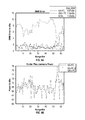
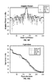
- FIG. 10A and FIG. 9A show the SINR error in dBs as a function of range-bin where it is noted that the average SINR error over all range-bins for the SCM-Radar scheme of (39)-(42), the KA PC-Radar scheme of (43)-(45), and the QKU PC-Radar scheme of (49)-(51).
- KA PC-Radar QKU PC-Radar and KU SCM-Radar are noted to yield an average SINR error of 0.87 dBs, 1.32 dBs and 7.59 dBs, respectively.
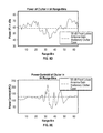
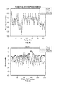
- FIG. 9B and FIG. 10B the total clutter plus jammer power of the KA PC-Radar, KU PC-Radar and QKU PC-Radar schemes is displayed.
- the two KU PC-Radar schemes are noted to yield the same total power for each range-bin.
- This total power is also noted to deviate greatly from that of the KA PC-Radar scheme that uses in its evaluations the “true” SAR range-bin clutter plus jammer.
- This deviation from the true case is due to the fact that the total clutter plus jammer power derived with a KU PC-Power scheme is simply the first moment m 1 of the sample covariance matrix (32), whose value depends on noisy on-line measurements.
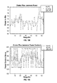
- FIGS. 9D and 9G and FIGS. 10D and 10G display results in dBs for the first range-bin of FIG. 8B . More specifically, in FIG. 9D and FIG. 10D the antenna gain modulated clutter is displayed for three cases.
- First from the actual SAR range-bin clutter covariance (18), i.e., ⁇ x i g i ⁇ t : i 1, . . . , NM ⁇ , second from KA PC-Radar covariance (27), i.e.,
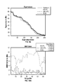
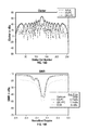
- FIGS. 8 e and 9 e the SINR is plotted versus Doppler for the Optimum-Radar, KA PC-Radar, QKU PC-Radar and SCM-Radar cases.
- FIGS. 9 f and 10 f the adapted patterns are presented for the Optimum-Radar, KA PC-Radar, QKU PC-Radar and SCM-Radar cases.
- FIG. 9G and FIG. 10G the eigenvalues of the interference plus noise covariance matrix versus eigenvalues index are plotted for the Optimum-Radar, KA PC-Radar, QKU PC-Radar and SCM-Radar cases.
- ⁇ n 2 is the average power of thermal white noise and I NM is an identity matrix of dimension NM by NM.
- the jammer covariance matrix (C J ) is defined according to:
- N J is the total number of jammers; 2) ⁇ J i is the boresight angle of the i th jammer; 3) is the Kronecker (or tensor) product; e) I M is an identity matrix of dimension M by M; f) 1 N ⁇ N is a unity matrix of dimension N by N; g) p i is the i th jammer power; and h) j ( ⁇ J i ) is the NM ⁇ 1 dimensional and complex i th jammer steering vector.
- JNR jammer to noise ratio
- ⁇ is the fractional part of A that remains after the range walk.
- C ICM internal clutter motion covariance
- f c is the carrier frequency in megahertz
- ⁇ is the wind speed in miles per hour
- r is the ratio between the dc and ac terms of the clutter Doppler power spectral density
- d) b is a shape factor that has been tabulated
- e) c is the speed of light
- f) T r is the pulse repetition interval.
- C CM channel mismatch covariance
- C NB , C FB and C AD are composite covariance matrix tapers that are defined next.
- FB finite (nonzero) bandwidth
- C FB C FB time ⁇ C FB space ( A ⁇ .18 )
- C FB time 1 M ⁇ M ( A ⁇ .19 )
- C FB space ] i , k ( 1 - ⁇ / 2 ) 2 ⁇ sin ⁇ ⁇ c 2 ⁇ ( ⁇ / 2 ) ⁇ ⁇ for ⁇ ⁇ i ⁇ k ( A ⁇ .20 )
- C AD C AD time ⁇ C AD space ( A ⁇ .22 )
- C AD time 1 M ⁇ M ( A ⁇ .23 )
- B is the bandwidth of an ideal bandpass filter and AO is a suitable measure of mainbeam width.
- ⁇ 1 , . . . , ⁇ N and ⁇ 1 , . . . , ⁇ N denote amplitude and phase errors, respectively.
- ⁇ m 1 x 1 ⁇ g 1 + x 2 ⁇ g 2 + x 3 ⁇ g 3 + x 4 ⁇ g 4 ( B ⁇ .6 )
- PC KU 4 + 1 2 + [ 1 3 ] 2 ⁇ m 1 ⁇ [ x 3 ⁇ g 3 - x 2 ⁇ g 2 x 4 ⁇ g 4 - x 1 ⁇ g 1 ] ( B ⁇ .12 )
- PC KU 4 + 1 2 - [ 1 ⁇ ⁇ 3 ] 2 ⁇ m 1 ⁇ [ sin ⁇ ( 2 ⁇ ⁇ ⁇ ⁇ d ⁇ ⁇ sin ⁇ ⁇ ⁇ 3 ) sin ⁇ ( 2 ⁇ ⁇ ⁇ ⁇ ⁇ d ⁇ ⁇ sin ⁇ ⁇ ⁇ 4 ) sin ⁇ ( 4 ⁇ ⁇ ⁇ ⁇ d ⁇ ⁇ sin ⁇ ⁇ ⁇ 3 ) sin ⁇ ( 4 ⁇ ⁇ ⁇ ⁇ d ⁇ ⁇ sin ⁇ ⁇ ⁇ 4 ) ] - 1 ⁇ [ Imag ⁇ [ m 2 ] Imag ⁇ [ m 3 ] ] ( B ⁇ .15 )
- thermal functions relate to the “sourcing and retention” of mass-energy that are measured with entropy metrics
- linger functions pertain to the “processing and motion” of mass-energy that are measured with ectropy metrics.
- thermo entropies The two thermo entropies and two linger ectropies are defined as follows:
- log 2 (1/P[ ⁇ i ]) denotes the “amount of thermal-uncertainty bits” associated with ⁇ i .
- log 2 (1/P[ ⁇ i ]) denotes the smallest possible thermal-uncertainty bits for ⁇ i .
- the expression 4 ⁇ r i 2 denotes the “amount of thermal-uncertainty square meters” corresponding to the surface area of a ⁇ i spherical volume.
- 4 ⁇ r i 2 denotes the smallest possible thermal-uncertainty surface area that an arbitrarily shaped volume for ⁇ i could have, i.e., that of a sphere.
- r in 4 ⁇ r 2 denotes an average radius for all microstate spheres.
- the linger-processor ectropy ( ⁇ circumflex over (K) ⁇ ) denotes the “amount of linger-certainty bors” of the system microstates according to the following “minimax certainty metric” (in mathematical binary operator or bor units):
- ⁇ ⁇ is the number of realizations of a microstate ⁇ i
- h i is the number of bits for processing under ⁇ i
- C[ ⁇ i ] is a “constraint” on the maximum number of inputs that a basic mathematical operator (or physical gate) can have under ⁇ i .
- log C[ ⁇ i ] h i denotes the “amount of linger-certainty bors” associated with ⁇ i where the approximation log C[ ⁇ i ] h i ⁇ square root over (h i ) ⁇ holds when C[ ⁇ i ] approaches the value of one and h i is a very large number.
- log C[ ⁇ i ] h i denotes the smallest possible amount of linger-certainty bors of processing under ⁇ i .
- log C[ ⁇ i ] h i ⁇ square root over (h i ) ⁇ for all i the h in ⁇ circumflex over (K) ⁇ ⁇ square root over (h) ⁇ denotes the maximum number of thermo-bit inputs linked to the microstate realization whose number of linger bors is the same as ⁇ circumflex over (K) ⁇ .
- ⁇ r i /v i denotes the “amount of linger-certainty seconds” corresponding to circular rotational motion on the surface of a sphere of radius r i with v i denoting the rotational speed of motion in ⁇ i .
- ⁇ r i /v i denotes the smallest possible linger-certainty seconds for rotational motion since v i is the largest possible in value.
- g Med is a function that depends in the type of medium studied (e.g., a black-hole, a photon-gas or a flexible-phase medium) that relates the source/processor metrics pair ( ⁇ , ⁇ circumflex over (K) ⁇ ), with mathematical units, to dimensionless operating ratios of physical variables, inclusive of the retainer/mover metrics pair ( ⁇ circumflex over (N) ⁇ , ⁇ ).
- QOO quantum of operation
- the ULTE is now stated for an uncharged and non-rotational black-hole, photon-gas and flexible-phase mediums, with their least “surface area” LTT expected volumes noted to be spherical in shape.
- the black-hole (BH) ULTE is given:
- the photon-gas ULTE is defined according to:
- the flexible-phase ULTE is defined according to:
- aspects of the present invention may be embodied as a system, method, or computer program product. Accordingly, aspects of the present invention may take the form of an entirely hardware embodiment, an entirely software embodiment (including firmware, resident software, micro-code, etc.), or an embodiment combining software and hardware aspects that may all generally be referred to herein as a “service,” “circuit,” “circuitry,” “module,” and/or “system.” Furthermore, aspects of the present invention may take the form of a computer program product embodied in one or more computer readable medium(s) having computer readable program code embodied thereon.
- the computer readable medium may be a non-transient computer readable signal medium or a computer readable storage medium.
- a computer readable storage medium may be, for example, but not limited to, an electronic, magnetic, optical, electromagnetic, infrared, or semiconductor system, apparatus, or device, or any suitable combination of the foregoing.
- a computer readable storage medium may be any tangible medium that can contain, or store a program for use by or in connection with an instruction execution system, apparatus, or device.
- Program code and/or executable instructions embodied on a computer readable medium may be transmitted using any appropriate medium, including but not limited to wireless, wireline, optical fiber cable, RF, etc., or any suitable combination of the foregoing.
- Computer program code for carrying out operations for aspects of the present invention may be written in any combination of one or more programming languages, including an object oriented programming language such as Java, Smalltalk, C++ or the like and conventional procedural programming languages, such as the “C” programming language or similar programming languages.
- the program code may execute entirely on the user's computer (device), partly on the user's computer, as a stand-alone software package, partly on the user's computer and partly on a remote computer or entirely on the remote computer or server.
- the remote computer may be connected to the user's computer through any type of network, including a local area network (LAN) or a wide area network (WAN), or the connection may be made to an external computer (for example, through the Internet using an Internet Service Provider).
- LAN local area network
- WAN wide area network
- Internet Service Provider for example, AT&T, MCI, Sprint, EarthLink, MSN, GTE, etc.
- These computer program instructions may also be stored in a computer readable medium that can direct a computer, other programmable data processing apparatus, or other devices to function in a particular manner, such that the instructions stored in the computer readable medium produce an article of manufacture including instructions which implement the function/act specified in the flowchart and/or block diagram block or blocks.
- the computer program instructions may also be loaded onto a computer, other programmable data processing apparatus, or other devices to cause a series of operational steps to be performed on the computer, other programmable apparatus or other devices to produce a computer implemented process such that the instructions which execute on the computer or other programmable apparatus provide processes for implementing the functions/acts specified in the flowchart and/or block diagram block or blocks.
- the processes and devices described in preceding sections of this specification are used in conjunction with a moving target indicator radar system and/or with one or more of the components associated therewith.
- a moving target indicator radar system and/or with one or more of the components associated therewith.
- These systems are well known to those skilled in the art and are described, e.g., in U.S. Pat. No. 2,811,715 (moving target indicator radar); U.S. Pat. No. 2,965,895 (two antenna airborne moving target search radar); U.S. Pat. No. 3,153,786 (moving target indicator canceller); U.S. Pat. No. 3,634,859 (moving target indicator with automatic clutter residue control), U.S. Pat. No. 3,781,882 (adaptive digital automatic gain control for MTI radar systems), U.S. Pat. No.
Landscapes
- Engineering & Computer Science (AREA)
- Radar, Positioning & Navigation (AREA)
- Remote Sensing (AREA)
- Computer Networks & Wireless Communication (AREA)
- Physics & Mathematics (AREA)
- General Physics & Mathematics (AREA)
- Radar Systems Or Details Thereof (AREA)
Abstract
Description
r=x+s (1)
y=w H r=w H(x+s)=w H x+w H s (2)
SINR=|w H s| 2 /w H Rw (3)
R=E[xx H] (4)
w*=R −1 s (5)
SINR*=s H R −1 s (6)
R=(C c f(θAAM)+C c b(θAAM))◯(C RW +C ICM +C CM)C J ◯C CM +C n (7)
C CM =C AD +C AIN +C FB (8)
where: 1) Cc f(θAAM) and Cc b(θAAM) are complex NM×NM front and back clutter covariances that are functions of the antenna array misalignment angle θAAM; 2) CAD, CAIN, CFB are composite and complex NM×NM “angle dependent (AD)”, “angel independent narrowband (AIN)” and “finite bandwidth (FB)” channel mismatch covariances, respectively, that are added to yield the total channel mismatch covariance CCM, see Appendix A; 3) CRW is a complex NM×NM range walk covariance, see Appendix A; 4) CICM is a complex NM×NM internal clutter motion covariance, see Appendix A; 5) Cn is a NM×NM thermal noise covariance, see Appendix A; and 6) the symbol “◯” denotes Hadamard term by term products of the elements of two matrices.
s=[s 1(θt) s 2(θt) . . . s M(θt)]T /√{square root over (NM)} (9)
s k(θt)=e j2π(k−1)
s 1(θt)=[s 1,1(θt)s 2,1(θt) . . . s N,1(θt)] (11)
s k,1(θt)=e j2π(k−1)
f D t=2v/λ=2(v/c)f c (14)
f r=1/T r (15)
θt=(d/λ)sin(θt) (16)
where: 1) θt is the value of the boresight angle (θ) where the target resides, θt=0° for the case displayed in
F. The Antenna Pattern
where: 1) θ denotes the boresight angle; 2) θi is the value of the boresight angle corresponding to the ith range-bin cell; 3) θt is the value of the boresight angle where the target of interest resides; 4) N is the number of antenna elements; 5) M is the number of pulses transmitted during the coherent pulse interval; 5) NM is the number of range-bin cells which is the same as the number of degrees of freedom; 6) d is the antenna inter-element spacing; 7) λ is the operating wavelength; and 8) Kf is the front antenna gain constant. Next the mathematical expression for the front clutter covariance matrix that the adaptive radar must evaluate on-line is described.
G. The Front Clutter Covariance Matrix:
where:
-
- 1) {xi: i=1, . . . , NM} are the clutter powers of the front range-bin where xi denotes the ith cell clutter power.
- 2) {gi θ
t : i=1, . . . , NM} are the NM gains of the antenna pattern (17) that points towards the target boresight angle θt. - 3) {xigi θ
t : i=1, . . . , NM} denotes the NM antenna gain modulated clutter powers of the front range-bin. - 4) {ci(θAAM): i=1, . . . , NM} denotes the NM steering vectors of the front range-bin cells whose values depend on the antenna array misalignment angle θAAM. In particular, ci(θAAM) denotes the ith cell steering vector, which is complex and MN dimensional, defined according to:
c i(θAAM)=[f c 1(θi,θAAM) . . . f c M(θi,θAAM) . . . fcM(θi,θAAM)]T (19)
c 1(θi)=[c 1,1(θi)c 2,1(θi) . . . c N,1(θi)] (21)
c k,1(θi)=e j2π(k−1)θ
β=(v p T r)/(d/2) (24)
-
- where 1) vp is the radar platform speed; 2)
θ i is the normalized θi, inclusive of the antenna array misalignment angle θAAM as seen from (25); and 3) β is the ratio of the distance traversed by the radar platform during the PRI, i.e., vpTr, to the half antenna inter-element spacing, d/2. The remaining parameters for expressions (19)-(25) were earlier defined for (9)-(16). Finally, it is noted that the first element of Cc f(θAAM) divided by the variance of the thermal white noise σn 2 defines the front clutter to noise ratio (CNRf), i.e.,
CNRf =C c f(1,1)/σn 2 (26) - 5) {ci(θAAM)ci H(θAAM): i=1, . . . , NM} denotes the set of cell steering matrices.
- where 1) vp is the radar platform speed; 2)
denotes the mathematical antenna pattern or MAP derived from (17) when it is directed towards the boresight angle θPC
where:
-
- 1) {x1, . . . , xNM} denotes the set of clutter powers of the NM range-bin cells.
- 2) (NM+1)/2 in (34) denotes the value that PCKU achieves when the clutter is stationary.
- 3) ΔPC(RSCM) denotes a RSCM dependent non-stationary clutter correction to the power centroid of stationary clutter.
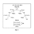
- 4) {m1, m2, . . . , mN+M−1} denotes a set of N+M−1 first row elements of the complex NM×NM dimensional sample covariance matrix RSCM. These N+M−1 elements are 2nd order statistical moments that are selected following the “column pattern” described in
FIG. 5 for the N=111=3 case. - 5) Imag[mi] denotes the imaginary part of the mi, moment.
- 6) {ki; i=2, . . . , N+M−1} is a set of gains that weights the contribution of {Imag[mi]; i=2, . . . , N+M−1} to the sum of imaginary moment values in (35) that results in ΔPC(RSCM).
| TABLE I |
| |
| 1. Antenna | Number of antenna elements: N = 16 |
| Number of CPI pulses: M = 16 | |
| Ratio of antennal inter element spacing to | |
| wavelength: d/λ = 1/2 | |
| Variance of thermal white noise (26): σn 2 = 1 | |
| Front antenna gain constant (17): Kf = 56 dBs | |
| Back antenna gain constant: Kb = −40 dBs | |
| Carrier frequency (14): fc = 109 Hz | |
| Pulse repetition frequency (15): fr = 103 Hz | |
| Antenna array misalignment (25): θAAM = 2° | |
| 2. Clutter | Number of Range-Bins NM = 256 |
| Radar's ratio β (24): β = 1 | |
| 3. Jammers | Jammers are used at the boresight angles of −60°, |
| −30° and 45° with 52, 55 and 66 JNRs in dBs, | |
| respectively, inclusive of antenna gains. | |
| 4. Range Walk | Fraction of remaining area after range walk |
| (A.12): ρ = 0.999999. | |
| 5. Internal Clutter | Shape factor, (A.14): b = 5.7 |
| Motion | Wind-speed, (A.16): ω = 15 |
| 6. Channel Mismatch: | Amplitude peak deviation, (A.20): Δε = 0.001, |
| Finite-Bandwidth | Phase peak deviation, (A.20): Δϕ = 0.1° |
| 7. Channel Mismatch: | Bandwidth, (A.24): B = 108 Hz |
| Angle-Dependent | Mainbeam width, (A.24): Δθ = 28.6° |
| 8. Channel Mismatch: | Amplitude error (A.29): Δεi = 0 for all i, |
| Angle-Independent | Phase-error (A.29): Δγi fluctuates with a 5° rms |
| for all i | |
Z i =R i 1/2 n i (42)
SINRKA =|w KA H s| 2 /w KA H Rw KA (43)
w KA ={circumflex over (R)} KA −1 s (44)
{circumflex over (R)} KA =R| C
SINRKU =|w KU H s| 2 /w KU H Rw KU (46)
w KU ={circumflex over (R)} KU −1 s (47)
{circumflex over (R)} KU =R| C
SINRQKU =|w QKU H s| 2 /w QKU H Rw QKU (49)
w QKU ={circumflex over (R)} QKU −1 s (50)
{circumflex over (R)} QKU =R| C
and thirdly from QKU PC-Radar (37), i.e.,
In
-
- 1. The SINR radar performance of both KA and KU PC-Radar emulates that of Optimum-Radar, which uses a covariance matrix tapers model for the interference plus noise covariance.
- 2. The SINR radar performance derived from both KA and KU PC-Radar represents a major improvement over KU SCM-Radar of more than 6 dBs for the considered illustration.
- 3. The KA PC-Radar scheme performs well with both uncompressed SAR imagery and “radar-blind compressed” SAR imagery because the range-bin power centroid derived from them do not vary greatly. This robustness observation led, in turn, to the discovery of “knowledge-unaided” PC-Radar.
- 4. The savings in on-line computational time of QKA PC-Radar over KA PC-Radar are significant because off-line computations of a small set of clutter covariance matrices permit their later fast extraction from a lookup memory.
- 5. The savings in storage space of KU PC-Radar over KA PC-Radar are significant because the storage of SAR imagery is unnecessary for power centroid evaluations.
- 6. The savings in on-line computational time of QKU PC-Radar over KU PC-Radar are significant because off-line computations of a small set of clutter covariance matrices permit their fast memory retrieves.
C n=σn 2 I NM (A.1)
JNR=C J(1,1)/σn 2 (A.8)
C RW =C RW time
[C R time]i,k=i,k=ρ|i−k| (A.10)
C RW space=1N×N (A.11)
ρ=ΔA/A=ΔA/{ΔRΔθ}=ΔA/{(c/B)Δθ} (A.12)
C CM =C NB ◯C FB ◯C AD (A.17)
C NB =qq H (A.26)
q=[q 1 q 2 . . . q M]T (A.27)
q k =q 1 for k=1, . . . ,M (A.28)
q 1=[ε1 e jγ
Ĥ=Σ i=1 Λ
where ΛĤ is the number of realizations of a microstate μi (describing a microscopic configuration of a thermodynamics system occupied with probability P[μi] in the course of thermal fluctuations). The expression log2(1/P[μi]) denotes the “amount of thermal-uncertainty bits” associated with μi. In addition, log2(1/P[μi]) denotes the smallest possible thermal-uncertainty bits for μi. Moreover, Ω in Ĥ=log2Ω denotes the ‘effective’ number of equally likely microstate realizations resulting in Ĥ. When the microstates are equally likely it follows that Ω and ΛĤ would be the same. Finally, Ĥ=log2 Ω=S/
{circumflex over (N)}=Σ i=1 Λ
where ΛĤ is the number of realizations of a microstate μi and
where ΛĤ is the number of realizations of a microstate μi, hi is the number of bits for processing under μi and C[μi] is a “constraint” on the maximum number of inputs that a basic mathematical operator (or physical gate) can have under μi. The expression logC[μ
{circumflex over (A)}=max{π
where ΛĤ is the number of realizations of a microstate μi and
-
- 1) The “mathematical units” entropy/ectropy equality
Ĥ={circumflex over (K)} 2 (C.6) - that surfaces from (C.3) when h is replaced with Ĥ.
- 2) The “physical units” entropy/ectropy extended relationship
- 1) The “mathematical units” entropy/ectropy equality
-
- that surfaces from the use of: a) equations (C.2) and (C.4); b) the equation for the escape speed (ve) from the medium:
v e 2=2v 2=2GM/r (C.8) - and derived under the assumption that the expected shape of the medium is that of a sphere of radius r whose mass-energy M=E/c2 is modeled as a point mass residing at its center (v denotes the perpetual rotational speed linked to the assumed point mass); and c) the equation of the “life-bits pace (Π)” defined according to (in SI sec/m3 units):
Π=τ/V=3τ/r{circumflex over (N)} (C.9) - where τ is the retention time of “thermo-bits of interest (or life-bits)” that defines a portion of the medium that leaves its expected spherical volume (V) via black-body radiation never to return. An example of “life-bits for a non-living system” are the thermo-bits of some compressed image such as the SAR image of
FIG. 8c , residing in a medium that also contains the thermo-bits of the PT source-coder that derived the image. Another example is of “life-bits for a living system” responsible for the day to day survival of an organism in a medium that also contains the thermo-bits that give the organism structure. - 3) The “physical units” QOO composite expression
- that surfaces from the use of: a) equations (C.2) and (C.4); b) the equation for the escape speed (ve) from the medium:
-
- that is appropriately derived from (C.7).
where all the variables were either implicitly or explicitly defined earlier in (C.1)-(C.10) except for: a) TBH denoting the temperature of the black-hole; b) G denoting the gravitational constant; c) ℏ denoting the reduced Planck constant; d)
where all the variables in (C.19)-(C.22) were earlier defined, and when applicable are redefined in the context of a photon-gas medium.
where: 1) g denotes the degeneracy of the ground energy state of the medium, e.g., for a water medium it has a value of one; 2) T denotes the medium temperature, e.g., T=310 K for liquid water (this special medium will be used here to model that of a 70 kg individual since more than 98% of our molecules are those of water which together contribute to more than 65% of our total mass); 3) m denotes the mass of a “massive particle” such as an atom or molecule, e.g., m=3×10⁻²⁶ kg for a H2O molecule; 4) cV is the heat capacity of a medium with constant volume, e.g., cV=3 for liquid water at 310 K; 5) β is a DoF coupling constant that acts as a ‘compression’ factor on the heat capacity of the medium and reflects non-equilibrium thermal conditions, e.g., β=0.7081 would lead to the compressed heat capacity of βcV=2.1243 for our example; 6) scVkT denotes the energy of a theoretical “thermal-energy particle”, e.g., βcVkT=9.0922×10⁻²¹ Joules for our running example (as a means of comparison the energy of an electron is of 8.187×10⁻¹⁴ Joules); 7) E=Mc2 is the “internal mass-energy” of the medium, e.g., for 70 kg of water, i.e., M=70 kg, one derives E=6.28×10¹⁸ Joules (as a means of comparison the internal energy (U) for an ideal gas model, which unlike the LTT flexible-phase model does not include the medium mass-energy, is given by U=cVkTM/m=108 Joules when T=1045 K and the cV, M and m values are those of our running example); 8) J=E/βcVkT is the number of thermal-energy particles in E, e.g., J=6.9193×1038 for our example; 9) Q is the QOO heat energy entering the medium during Δτ, e.g., Q=7.5825×10⁶ Joules for a human consuming 1,814 kcal per day where Δτ=1 day and the conversion factor of μ=4.18 Joules/cal is used; 10) ΔS=Q/T is the Classius entropy contributed to the medium at temperature T by Q during Δτ; e.g., ΔS=2.446×10⁴ Joules/K for our example; 11) ΔM=Q/Θμ is the mass equivalent for the energy Q that is expressed as the ratio of Q to the product of Σ and μ with Θ=5,000 kcal/kg and μ=4.18 Joules/cal, e.g., ΔM=0.3628 kg for our example; 12) Δm=kT ln(τ/Δτ)/Θμ, denotes a fraction of the massive particle m (or QOO m) that is expressed as the ratio of the lifespan-weighted thermal-energy term kT ln(τ/Δτ) to product of Θ and μ, e.g., Δm=2.1538×10⁻²⁷ kg when Δτ=1 day=1/365 year and the lifespan (τ) of the life-bits in the medium is of 102 years (as a means of comparison the mass of a hydrogen atom (mH) is 1.6667×10⁻²⁷ kg); 13) ⋄EΔτ Q=Q is the QOR energy that leaves the medium during Δτ and is the same as the operating heat energy Q that enter it (this operation is a control or compensating action from the surroundings of the medium that maintains the medium mass-energy E=Mc2 constant with the passing of time); 14) ΔJ=ΔM/Δm=Q/kT ln(τ/Δτ) denotes the fraction of the total number of thermal-energy particles J of the medium which equals the ratio of ΔM to Δm or equivalently the ratio of Q to kT ln(τ/Δτ), e.g., ΔJ=1.6831×1026 for our running example; 15) ⋄EΔτ LB=ΔJkT=⋄EΔτ Q/ln(τ/Δτ) denotes a ‘life-bits (LBs) energy’ fraction of the QOR radiation energy (ΔEΔτ Q) with the fraction factor given by the reciprocal of the lifespan expression ln(τ/Δτ), e.g., ⋄EΔτ LB=7.2082×10⁵ Joules for our running example which is 9.5% of the total emitted radiation ⋄EΔτ Q; and 16) NΔτ LB=⋄EΔτ LB/⋄EΔτ
Claims (14)
Priority Applications (1)
| Application Number | Priority Date | Filing Date | Title |
|---|---|---|---|
| US14/699,335 US10101445B2 (en) | 2014-04-29 | 2015-04-29 | Power centroid radar |
Applications Claiming Priority (2)
| Application Number | Priority Date | Filing Date | Title |
|---|---|---|---|
| US201461985783P | 2014-04-29 | 2014-04-29 | |
| US14/699,335 US10101445B2 (en) | 2014-04-29 | 2015-04-29 | Power centroid radar |
Publications (2)
| Publication Number | Publication Date |
|---|---|
| US20180074184A1 US20180074184A1 (en) | 2018-03-15 |
| US10101445B2 true US10101445B2 (en) | 2018-10-16 |
Family
ID=61558714
Family Applications (1)
| Application Number | Title | Priority Date | Filing Date |
|---|---|---|---|
| US14/699,335 Active 2037-04-25 US10101445B2 (en) | 2014-04-29 | 2015-04-29 | Power centroid radar |
Country Status (1)
| Country | Link |
|---|---|
| US (1) | US10101445B2 (en) |
Cited By (2)
| Publication number | Priority date | Publication date | Assignee | Title |
|---|---|---|---|---|
| US11766654B2 (en) | 2021-09-21 | 2023-09-26 | Erlan H. Feria | Method for controlling temperature of a chemical reaction |
| US11998884B1 (en) | 2023-03-02 | 2024-06-04 | Erlan H. Feria | Method for controlling lingerature of chemical reaction |
Families Citing this family (2)
| Publication number | Priority date | Publication date | Assignee | Title |
|---|---|---|---|---|
| US12587867B2 (en) * | 2021-07-14 | 2026-03-24 | Qualcomm Incorporated | Interference management for dynamic spectrum sharing |
| CN121348270B (en) * | 2025-12-18 | 2026-04-03 | 伽利略(天津)技术有限公司 | Methods and Systems for Modeling and Adaptive Suppression of Clutter Background in Radar Systems |
Citations (40)
| Publication number | Priority date | Publication date | Assignee | Title |
|---|---|---|---|---|
| US2811715A (en) | 1950-10-02 | 1957-10-29 | Jr Charles T Baker | Moving target indicator radar |
| US2965895A (en) | 1951-05-22 | 1960-12-20 | Jesse J Blasingame | Two antenna airborne moving target search radar |
| US3634859A (en) | 1967-08-08 | 1972-01-11 | Us Air Force | Moving target indicator with automatic clutter residue control |
| US3727220A (en) | 1971-09-13 | 1973-04-10 | Technology Service Corp | Adaptive receiving array method and apparatus for mti radar |
| US3781882A (en) | 1970-09-30 | 1973-12-25 | Hughes Aircraft Co | Adaptive digital automatic gain control for mti radar systems |
| US3879729A (en) | 1973-07-23 | 1975-04-22 | Gen Electric | Moving target indicator with minimum clutter interference |
| US3962704A (en) | 1974-05-31 | 1976-06-08 | Hughes Aircraft Company | Moving target indicator clutter tracker |
| US4720712A (en) * | 1985-08-12 | 1988-01-19 | Raytheon Company | Adaptive beam forming apparatus |
| DE3639500A1 (en) | 1986-11-20 | 1988-06-01 | Forschungsgesellschaft Fuer An | Radar receiver for mobile radar apparatuses having an antenna array with clutter suppression which acts in a two-dimensional manner |
| US5341142A (en) | 1987-07-24 | 1994-08-23 | Northrop Grumman Corporation | Target acquisition and tracking system |
| US5602760A (en) | 1994-02-02 | 1997-02-11 | Hughes Electronics | Image-based detection and tracking system and processing method employing clutter measurements and signal-to-clutter ratios |
| US5617099A (en) * | 1996-01-22 | 1997-04-01 | Hughes Aircraft Company | Adaptive filtering of matched-filter data |
| US5760734A (en) * | 1996-11-18 | 1998-06-02 | Lockheed Martin Corp. | Radar clutter removal by matrix processing |
| US5907568A (en) | 1996-11-22 | 1999-05-25 | Itt Manufacturing Enterprises, Inc. | Integrated precision approach radar display |
| US6292592B1 (en) * | 1998-10-19 | 2001-09-18 | Raytheon Company | Efficient multi-resolution space-time adaptive processor |
| US20010027392A1 (en) | 1998-09-29 | 2001-10-04 | William M. Wiese | System and method for processing data from and for multiple channels |
| US6400306B1 (en) * | 1999-12-17 | 2002-06-04 | Sicom Systems, Ltd | Multi-channel moving target radar detection and imaging apparatus and method |
| US20020152253A1 (en) * | 2000-08-29 | 2002-10-17 | Ricks David Charles | System and method for adaptive filtering |
| US6600446B2 (en) | 2001-06-29 | 2003-07-29 | Lockheed Martin Corporation | Cascadable architecture for digital beamformer |
| WO2004077093A1 (en) | 2002-12-20 | 2004-09-10 | Telefonaktiebolaget Lm Ericsson (Publ) | Adaptive ground clutter cancellation |
| US20050027519A1 (en) | 1998-11-09 | 2005-02-03 | Xinde Li | System and method for processing low signal-to-noise ratio signals |
| US20050237236A1 (en) * | 2004-04-26 | 2005-10-27 | Budic Robert D | Method and apparatus for performing bistatic radar functions |
| US20050280571A1 (en) * | 2004-06-17 | 2005-12-22 | The Boeing Company | System, method and computer program product for detecting and tracking a moving ground target having a single phase center antenna |
| US20060039626A1 (en) | 2004-08-23 | 2006-02-23 | Canon Kabushiki Kaisha | Data transformation apparatus and method |
| US7009533B1 (en) | 2004-02-13 | 2006-03-07 | Samplify Systems Llc | Adaptive compression and decompression of bandlimited signals |
| US20060181451A1 (en) * | 2005-02-14 | 2006-08-17 | Honeywell International Inc. | System and method for combining displaced phase center antenna and space-time adaptive processing techniques to enhance clutter suppression in radar on moving platforms |
| US20060220956A1 (en) * | 2003-03-21 | 2006-10-05 | Richardson Peter G | Time delay beamformer and method of time delay beamforming |
| US7145971B2 (en) | 1996-08-29 | 2006-12-05 | Cisco Technology, Inc. | Spatio-temporal processing for communication |
| US20070285315A1 (en) * | 2004-01-13 | 2007-12-13 | Davis Dennis W | Phase arrays exploiting geometry phase and methods of creating such arrays |
| US7415065B2 (en) | 2002-10-25 | 2008-08-19 | Science Applications International Corporation | Adaptive filtering in the presence of multipath |
| US20090322612A1 (en) * | 2006-05-10 | 2009-12-31 | Research Foundation Of The City University Of New York | Methods and applications utilizing signal source memory space compression and signal processor computational time compression |
| US20100019957A1 (en) * | 2006-04-11 | 2010-01-28 | Feria Erlan H | Time-compressed clutter covariance signal processor |
| US7903024B2 (en) | 2007-10-25 | 2011-03-08 | Lockheed Martin Corporation | Adaptive moving target indicator (MTI) clutter rejection filter for radar systems |
| US20110241931A1 (en) * | 2010-04-01 | 2011-10-06 | Massachusetts Institute Of Technology | Iterative clutter calibration with phased array antennas |
| US20120062409A1 (en) * | 2010-09-10 | 2012-03-15 | Man-On Pun | Method for detecting targets using space-time adaptive processing and shared knowledge of the environment |
| US20120127027A1 (en) * | 2010-11-24 | 2012-05-24 | Zafer Sahinoglu | Persymmetric Parametric Adaptive Matched Filters for Detecting Targets Using Space-Time Adaptive Processing of Radar Signals |
| US20120249361A1 (en) * | 2011-04-04 | 2012-10-04 | Zafer Sahinoglu | Method for Detecting Targets Using Space-Time Adaptive Processing |
| US20120256787A1 (en) * | 2011-04-06 | 2012-10-11 | Junichiro Suzuki | Radar reception signal processing apparatus and method thereof |
| US20120268325A1 (en) * | 2011-04-21 | 2012-10-25 | Hansen Charles T | Maximum likelihood angle estimation of wideband signals using phased array antennas |
| US9772402B2 (en) * | 2014-06-09 | 2017-09-26 | Src, Inc. | Multiplatform GMTI radar with adaptive clutter suppression |
-
2015
- 2015-04-29 US US14/699,335 patent/US10101445B2/en active Active
Patent Citations (42)
| Publication number | Priority date | Publication date | Assignee | Title |
|---|---|---|---|---|
| US2811715A (en) | 1950-10-02 | 1957-10-29 | Jr Charles T Baker | Moving target indicator radar |
| US2965895A (en) | 1951-05-22 | 1960-12-20 | Jesse J Blasingame | Two antenna airborne moving target search radar |
| US3634859A (en) | 1967-08-08 | 1972-01-11 | Us Air Force | Moving target indicator with automatic clutter residue control |
| US3781882A (en) | 1970-09-30 | 1973-12-25 | Hughes Aircraft Co | Adaptive digital automatic gain control for mti radar systems |
| US3727220A (en) | 1971-09-13 | 1973-04-10 | Technology Service Corp | Adaptive receiving array method and apparatus for mti radar |
| US3879729A (en) | 1973-07-23 | 1975-04-22 | Gen Electric | Moving target indicator with minimum clutter interference |
| US3962704A (en) | 1974-05-31 | 1976-06-08 | Hughes Aircraft Company | Moving target indicator clutter tracker |
| US4720712A (en) * | 1985-08-12 | 1988-01-19 | Raytheon Company | Adaptive beam forming apparatus |
| DE3639500A1 (en) | 1986-11-20 | 1988-06-01 | Forschungsgesellschaft Fuer An | Radar receiver for mobile radar apparatuses having an antenna array with clutter suppression which acts in a two-dimensional manner |
| US5341142A (en) | 1987-07-24 | 1994-08-23 | Northrop Grumman Corporation | Target acquisition and tracking system |
| US5602760A (en) | 1994-02-02 | 1997-02-11 | Hughes Electronics | Image-based detection and tracking system and processing method employing clutter measurements and signal-to-clutter ratios |
| US5617099A (en) * | 1996-01-22 | 1997-04-01 | Hughes Aircraft Company | Adaptive filtering of matched-filter data |
| US7145971B2 (en) | 1996-08-29 | 2006-12-05 | Cisco Technology, Inc. | Spatio-temporal processing for communication |
| US5760734A (en) * | 1996-11-18 | 1998-06-02 | Lockheed Martin Corp. | Radar clutter removal by matrix processing |
| US5907568A (en) | 1996-11-22 | 1999-05-25 | Itt Manufacturing Enterprises, Inc. | Integrated precision approach radar display |
| US20010027392A1 (en) | 1998-09-29 | 2001-10-04 | William M. Wiese | System and method for processing data from and for multiple channels |
| US6292592B1 (en) * | 1998-10-19 | 2001-09-18 | Raytheon Company | Efficient multi-resolution space-time adaptive processor |
| US20050027519A1 (en) | 1998-11-09 | 2005-02-03 | Xinde Li | System and method for processing low signal-to-noise ratio signals |
| US6400306B1 (en) * | 1999-12-17 | 2002-06-04 | Sicom Systems, Ltd | Multi-channel moving target radar detection and imaging apparatus and method |
| US20020152253A1 (en) * | 2000-08-29 | 2002-10-17 | Ricks David Charles | System and method for adaptive filtering |
| US6600446B2 (en) | 2001-06-29 | 2003-07-29 | Lockheed Martin Corporation | Cascadable architecture for digital beamformer |
| US7415065B2 (en) | 2002-10-25 | 2008-08-19 | Science Applications International Corporation | Adaptive filtering in the presence of multipath |
| WO2004077093A1 (en) | 2002-12-20 | 2004-09-10 | Telefonaktiebolaget Lm Ericsson (Publ) | Adaptive ground clutter cancellation |
| US20060220956A1 (en) * | 2003-03-21 | 2006-10-05 | Richardson Peter G | Time delay beamformer and method of time delay beamforming |
| US20070285315A1 (en) * | 2004-01-13 | 2007-12-13 | Davis Dennis W | Phase arrays exploiting geometry phase and methods of creating such arrays |
| US7009533B1 (en) | 2004-02-13 | 2006-03-07 | Samplify Systems Llc | Adaptive compression and decompression of bandlimited signals |
| US20050237236A1 (en) * | 2004-04-26 | 2005-10-27 | Budic Robert D | Method and apparatus for performing bistatic radar functions |
| US20050280571A1 (en) * | 2004-06-17 | 2005-12-22 | The Boeing Company | System, method and computer program product for detecting and tracking a moving ground target having a single phase center antenna |
| US20060039626A1 (en) | 2004-08-23 | 2006-02-23 | Canon Kabushiki Kaisha | Data transformation apparatus and method |
| US20060181451A1 (en) * | 2005-02-14 | 2006-08-17 | Honeywell International Inc. | System and method for combining displaced phase center antenna and space-time adaptive processing techniques to enhance clutter suppression in radar on moving platforms |
| US8098196B2 (en) * | 2006-04-11 | 2012-01-17 | Research Foundation Of The City University Of New York | Time-compressed clutter covariance signal processor |
| US20100019957A1 (en) * | 2006-04-11 | 2010-01-28 | Feria Erlan H | Time-compressed clutter covariance signal processor |
| US20090322612A1 (en) * | 2006-05-10 | 2009-12-31 | Research Foundation Of The City University Of New York | Methods and applications utilizing signal source memory space compression and signal processor computational time compression |
| US7773032B2 (en) * | 2006-05-10 | 2010-08-10 | Research Foundation Of The City University Of New York | Methods and applications utilizing signal source memory space compression and signal processor computational time compression |
| US7903024B2 (en) | 2007-10-25 | 2011-03-08 | Lockheed Martin Corporation | Adaptive moving target indicator (MTI) clutter rejection filter for radar systems |
| US20110241931A1 (en) * | 2010-04-01 | 2011-10-06 | Massachusetts Institute Of Technology | Iterative clutter calibration with phased array antennas |
| US20120062409A1 (en) * | 2010-09-10 | 2012-03-15 | Man-On Pun | Method for detecting targets using space-time adaptive processing and shared knowledge of the environment |
| US20120127027A1 (en) * | 2010-11-24 | 2012-05-24 | Zafer Sahinoglu | Persymmetric Parametric Adaptive Matched Filters for Detecting Targets Using Space-Time Adaptive Processing of Radar Signals |
| US20120249361A1 (en) * | 2011-04-04 | 2012-10-04 | Zafer Sahinoglu | Method for Detecting Targets Using Space-Time Adaptive Processing |
| US20120256787A1 (en) * | 2011-04-06 | 2012-10-11 | Junichiro Suzuki | Radar reception signal processing apparatus and method thereof |
| US20120268325A1 (en) * | 2011-04-21 | 2012-10-25 | Hansen Charles T | Maximum likelihood angle estimation of wideband signals using phased array antennas |
| US9772402B2 (en) * | 2014-06-09 | 2017-09-26 | Src, Inc. | Multiplatform GMTI radar with adaptive clutter suppression |
Cited By (3)
| Publication number | Priority date | Publication date | Assignee | Title |
|---|---|---|---|---|
| US11766654B2 (en) | 2021-09-21 | 2023-09-26 | Erlan H. Feria | Method for controlling temperature of a chemical reaction |
| US11998884B1 (en) | 2023-03-02 | 2024-06-04 | Erlan H. Feria | Method for controlling lingerature of chemical reaction |
| US12390784B2 (en) | 2023-03-02 | 2025-08-19 | Erlan H. Feria | Method for controlling lingerature of chemical reaction |
Also Published As
| Publication number | Publication date |
|---|---|
| US20180074184A1 (en) | 2018-03-15 |
Similar Documents
| Publication | Publication Date | Title |
|---|---|---|
| CN110261841B (en) | Single-measurement vector DOA estimation method for MIMO radar based on iteratively weighted near-end projection | |
| US10571550B2 (en) | Signal correction for environmental distortion | |
| US10101445B2 (en) | Power centroid radar | |
| Yang et al. | Knowledge‐aided STAP with sparse‐recovery by exploiting spatio‐temporal sparsity | |
| Rosenberg et al. | Coherent detection in medium grazing angle sea‐clutter | |
| Tao et al. | A knowledge aided SPICE space time adaptive processing method for airborne radar with conformal array | |
| Li et al. | A fast and gridless STAP algorithm based on mixed‐norm minimisation and the alternating direction method of multipliers | |
| CN107526064A (en) | Adaptive LFM modulated parameter estimating methods based on two dimensional character | |
| Sun et al. | Registration-based compensation using sparse representation in conformal-array STAP | |
| Dong et al. | Direction-of-arrival tracking using a co-prime microphone array: A particle filter perspective | |
| CN114966526B (en) | A method for estimating direction of arrival | |
| Pulido et al. | Kernel embedded nonlinear observational mappings in the variational mapping particle filter | |
| Xiao et al. | A robust refined training sample reweighting space–time adaptive processing method for airborne radar in heterogeneous environment | |
| Li et al. | KT and azimuth sub‐region deramp‐based high‐squint SAR imaging algorithm mounted on manoeuvring platforms | |
| CN109633635A (en) | Meter wave radar height measurement method based on structuring recurrence least square | |
| CN120110467A (en) | Multi-band smart antenna array beamforming method, device, equipment and medium | |
| US11194014B1 (en) | System, method and apparatus for recovering polarization radar data | |
| Xu et al. | Closed expression of source signal's DOA information in sensor array | |
| CN114994631B (en) | Non-convex relaxation atomic norm space-time moving target parameter estimation method | |
| Peng et al. | Robust knowledge‐aided sparse recovery STAP method for non‐homogeneity clutter suppression | |
| Tang et al. | Robust beam tracking for 3D manoeuvrable UAV in DFRC systems | |
| Deng et al. | Cascaded interference suppression method based on sparse representation for airborne passive radar | |
| Zhou et al. | Sparse Bayesian learning‐based mainlobe blanket jamming suppression algorithm | |
| Zhang et al. | An improved gray wolf algorithm for radiation near-field source localization in exact model | |
| McDonald et al. | Clairvoyant radar sea clutter covariance matrix modelling |
Legal Events
| Date | Code | Title | Description |
|---|---|---|---|
| AS | Assignment |
Owner name: RESEARCH FOUNDATION OF THE CITY UNIVERSITY OF NEW Free format text: ASSIGNMENT OF ASSIGNORS INTEREST;ASSIGNOR:FERIA, ERLAN;REEL/FRAME:035783/0384 Effective date: 20150603 |
|
| STCF | Information on status: patent grant |
Free format text: PATENTED CASE |
|
| MAFP | Maintenance fee payment |
Free format text: PAYMENT OF MAINTENANCE FEE, 4TH YR, SMALL ENTITY (ORIGINAL EVENT CODE: M2551); ENTITY STATUS OF PATENT OWNER: SMALL ENTITY Year of fee payment: 4 |
|
| MAFP | Maintenance fee payment |
Free format text: PAYMENT OF MAINTENANCE FEE, 8TH YR, SMALL ENTITY (ORIGINAL EVENT CODE: M2552); ENTITY STATUS OF PATENT OWNER: SMALL ENTITY Year of fee payment: 8 |