US10100630B2 - Method and apparatus for communicating incremental depth and/or other useful data of a downhole tool - Google Patents
Method and apparatus for communicating incremental depth and/or other useful data of a downhole tool Download PDFInfo
- Publication number
- US10100630B2 US10100630B2 US14/621,007 US201514621007A US10100630B2 US 10100630 B2 US10100630 B2 US 10100630B2 US 201514621007 A US201514621007 A US 201514621007A US 10100630 B2 US10100630 B2 US 10100630B2
- Authority
- US
- United States
- Prior art keywords
- downhole
- assembly
- downhole assembly
- drilling
- depth
- Prior art date
- Legal status (The legal status is an assumption and is not a legal conclusion. Google has not performed a legal analysis and makes no representation as to the accuracy of the status listed.)
- Expired - Fee Related, expires
Links
Images


Classifications
-
- E—FIXED CONSTRUCTIONS
- E21—EARTH OR ROCK DRILLING; MINING
- E21B—EARTH OR ROCK DRILLING; OBTAINING OIL, GAS, WATER, SOLUBLE OR MELTABLE MATERIALS OR A SLURRY OF MINERALS FROM WELLS
- E21B47/00—Survey of boreholes or wells
- E21B47/04—Measuring depth or liquid level
-
- E—FIXED CONSTRUCTIONS
- E21—EARTH OR ROCK DRILLING; MINING
- E21B—EARTH OR ROCK DRILLING; OBTAINING OIL, GAS, WATER, SOLUBLE OR MELTABLE MATERIALS OR A SLURRY OF MINERALS FROM WELLS
- E21B45/00—Measuring the drilling time or rate of penetration
-
- E21B47/124—
-
- E—FIXED CONSTRUCTIONS
- E21—EARTH OR ROCK DRILLING; MINING
- E21B—EARTH OR ROCK DRILLING; OBTAINING OIL, GAS, WATER, SOLUBLE OR MELTABLE MATERIALS OR A SLURRY OF MINERALS FROM WELLS
- E21B47/00—Survey of boreholes or wells
- E21B47/12—Means for transmitting measuring-signals or control signals from the well to the surface, or from the surface to the well, e.g. for logging while drilling
- E21B47/14—Means for transmitting measuring-signals or control signals from the well to the surface, or from the surface to the well, e.g. for logging while drilling using acoustic waves
- E21B47/18—Means for transmitting measuring-signals or control signals from the well to the surface, or from the surface to the well, e.g. for logging while drilling using acoustic waves through the well fluid, e.g. mud pressure pulse telemetry
-
- E—FIXED CONSTRUCTIONS
- E21—EARTH OR ROCK DRILLING; MINING
- E21B—EARTH OR ROCK DRILLING; OBTAINING OIL, GAS, WATER, SOLUBLE OR MELTABLE MATERIALS OR A SLURRY OF MINERALS FROM WELLS
- E21B47/00—Survey of boreholes or wells
- E21B47/26—Storing data down-hole, e.g. in a memory or on a record carrier
Definitions
- Downhole drilling for oil and gas typically involves an operator drilling a well by rotating a drillstring having a drill bit attached, and using the system to bore through a formation.
- a rotary table or a top drive rotates the drillstring.
- a bottom hole assembly (BHA) on the drillstring has increased weight and provides necessary force on the assembly's drill bit to optimize the rate of penetration (ROP) of the system while drilling through the formation, thereby increasing drilling efficiency.
- ROP rate of penetration
- downhole sensors are disposed along the body of the drillstring and are used for measuring geophysical properties of the surrounding wellbore during drilling operations.
- MWD operations it is also commonly desired for the operator to take periodic measurements downhole using the downhole sensors, at particular sampling rates (i.e., based on timing) per the distance drilled in the wellbore.
- sampling rates may vary, requiring many measurements per drilled foot within the wellbore or requiring fewer measurements per drilled foot.
- the downhole sensors may take too few measurements (e.g., if the ROP increases to a rate faster than the sensors had been originally set to take measurements), or the sensors may take measurements too often (e.g., if the ROP decreases).
- the formation that the drill bit bores through downhole may be very dense, causing the ROP to decrease to the point that the sensors take redundant measurements (i.e., the sensors actually take multiple snapshots of the same data).
- the downhole sensors are unaware of the drilling depth or the rate that the drilling depth changes (i.e., the ROP), the sensors may take multiple, repetitive measurements unnecessarily downhole. This leads to needless power consumption and memory storage capacity issues downhole.
- Different forms of data can be useful downhole during operations.
- information related to time, depth, and/or ROP could be useful for operating the downhole sensors and other components of the downhole assembly.
- other devices downhole such as rotary steerable tools, directional drilling equipment, etc., can also benefit from different forms of information, such as incremental depth or real-time depth.
- U.S. Pat. No. 4,763,258 discloses how information can be communicated to a microprocessor downhole via an inclinometer and magnetometer by selectively rotating a drillstring during a data time interval through a predetermined magnitude of angular displacement or angular velocity.
- U.S. Pat. No. 6,267,185 discloses how a drillstring can be rotated at surface sequentially through one or more discrete angles of rotation or at different angular rates to generate a command code. The sequence of discrete angular rotations or angular rates is sensed downhole by a gyroscope and decoded as a command in a microprocessor, which transmits the decoded command to controlled equipment.
- the various telemetry techniques typically require special equipment, may be incapable of being performed while drilling a borehole, and may adversely affect operations.
- many of these solutions may be very cumbersome, may be manual in nature, and may require particular transmission windows of time for communicating encoded data. Due to these issues with known solutions in the art, as well as the slow rates of data transmission and the disruptive nature these solutions contribute to drilling operations, it is impractical to use these solutions to transmit useful data (e.g., time, depth, and/or ROP information) to the BHA.
- a method and apparatus communicates incremental depth and/or other useful data of a downhole tool.
- the incremental depth and/or other useful data of the downhole tool is communicated by measuring at least one change in the downhole system, detecting the change downhole, and subsequently determining the incremental depth and/or other useful data of the downhole tool.
- a downhole tool having a drill collar disposed on a drillstring and having downhole control circuitry. At least one angular rate sensor is disposed on the drill collar and is communicatively coupled to the downhole control circuitry.
- a rotational drive is mechanically coupled to the drill collar, and a rotational drive controller is communicatively coupled to the rotational drive.
- the rotational drive controller and the downhole control circuitry are configured with a predetermined rate change and a predetermined depth change. An actual depth change of the drillstring is measured, and the rate of the drillstring is changed using the rotational drive when the actual depth change of the drillstring and the predetermined depth change of the drillstring are at least the same.
- At least one predetermined depth interval is stored in the downhole assembly. Changes from different rotational rates imparted to the downhole assembly are detected using an angular rate sensor of the downhole assembly. A downhole depth value for the downhole assembly is determined using processing circuitry of the downhole assembly based on the detected changes in the different rotational rates correlated to the at least one predetermined depth interval stored in the downhole assembly. An operation of the downhole assembly is controlled based on the determined depth value.
- a downhole assembly is used for drilling a borehole.
- the assembly includes a drilling component, storage, an angular rate sensor, and processing circuitry.
- the drilling component is disposed on the assembly and drills the borehole with rotation.
- the storage is disposed on the assembly and stores at least one predetermined depth interval.
- the angular rate sensor is disposed on the assembly and detects the rotation.
- the processing circuitry is disposed on the assembly and is operatively coupled to the storage and the angular rate sensor. The processing circuitry determines a downhole depth value of the downhole assembly based on successive changes detected in the rotation of the downhole assembly correlated to the at least one predetermined depth interval stored in the storage.
- At least one predetermined depth interval in the downhole assembly is stored.
- At least one angular rate sensor is configured on the downhole assembly to detect different rotational rates.
- the borehole is drilled with the downhole assembly by: advancing the downhole assembly in the borehole, measuring with the surface equipment successive ones of the at least one predetermined depth interval, and alternatingly imparting rotation to the downhole assembly with the different rotational rates for the successive ones of the at least one predetermined depth interval.
- a drilling system is used for downlinking depth information from a surface to a downhole assembly used in drilling a borehole.
- the system includes storage, a drive, surface equipment, and control circuitry.
- the storage stores at least one predetermined depth interval.
- the drive imparts rotation to the downhole assembly to drill the borehole, and the surface equipment advances the downhole assembly in the borehole and measures successive ones of at least one predetermined depth interval.
- the control circuitry is operatively coupled to the storage, the drive, and the surface equipment. The control circuitry alternatingly imparts the rotation to the downhole assembly with different rotational rates for the successive ones of the at least one predetermined depth interval.
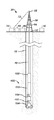
- FIG. 1 illustrates a drilling system according to the present disclosure.
- FIGS. 2A-2B illustrate a downhole assembly for the system in more detail.
- FIG. 3 schematically illustrates a detailed view of an angular rate sensor for the disclosed downhole assembly according to the present disclosure.
- FIGS. 4A-4B illustrates how the angular rate sensor in FIG. 3 is responsive to changes in RPM relative to the downhole assembly.
- FIG. 5 illustrates a schematic view of a drawworks system having an encoder.
- FIG. 6 illustrates a process of communicating incremental depth data downhole according to the present disclosure.
- FIG. 7 illustrates an arrangement of sensors on a downhole assembly disposed in a wellbore according to the present disclosure.
- FIG. 8 illustrates another arrangement of sensors on a downhole assembly disposed in a wellbore according to the present disclosure.
- FIG. 9 illustrates a direction drilling tool on a downhole assembly disposed in a wellbore according to the present disclosure.
- FIG. 10 illustrates a process of communicating data downhole by detecting changes in the system according to the present disclosure.
- FIG. 1 illustrates a drilling system 20 drilling a borehole 10 penetrating an earth formation.
- the system 20 has a drilling assembly 100 (e.g., a bottom hole assembly) suspended from a drillstring 40 .
- a derrick structure 58 supports the drillstring 40 and has a crown block 56 at the top.
- a traveling block 54 moveably connected to the crown block 56 connects to the drillstring 40
- a drawworks control 70 releases or detracts a cable 72 to raise or lower the traveling block 54 , which in turn raises or lowers the drillstring 40 .
- a rotary control 60 controls rotation of a rotary table 52 , thereby rotating the drillstring 40 , and surface equipment 30 having processing circuitry, memory, telemetry equipment, and the like can provide controls for the system 20 .
- the drilling assembly 100 includes one or more stabilizers 102 , a drill bit 104 , a drill collar 106 , a monitoring tool 110 , and other conventional components.
- the assembly 100 may also include components, such as a motor, a directional drilling tool 108 (e.g., a rotary steerable tool), or the like.
- the rotary table 52 imparts rotation to the drill bit 104 by rotating the drillstring 40 and downhole assembly 100 , and the rotary control 60 typically controls the drillstring's rotational speed.
- a drilling fluid system 65 circulates drilling fluid or “mud” from the surface downward through the drillstring 40 .
- the mud exits through the drill bit 104 and then returns cuttings to the surface via the annulus.
- motor rotation imparts rotation to the drill bit 104 through a shaft.
- the motor may have a bent sub, which can be used to direct the trajectory of the advancing borehole 10 .
- FIGS. 2A-2B show the monitoring tool 110 of the downhole assembly 100 in more detail.
- the tool 110 has a sensor section 120 , a power section 114 , an electronics section 116 , and a telemetry section 118 .
- the sensor section 120 has sensor elements 130 , which can include accelerometers 132 and magnetometers 134 to indicate the orientation (azimuth, inclination, and toolface) of the downhole assembly 100 within the borehole 10 .
- the sensor section 120 can also have other sensors used in Measurement-While-Drilling (MWD) and Logging-While-Drilling (LWD) operations including, but not limited to, sensors responsive to gamma radiation, neutron radiation, and electromagnetic fields.
- MWD Measurement-While-Drilling
- LWD Logging-While-Drilling
- the electronics section 116 houses electronic circuitry to operate and control other elements within the downhole assembly 100 and includes memory 150 for storing operational parameters and measurements made by the sensor section 120 .
- the electronics section 116 also includes processing circuitry (i.e., one or more processors) 140 to process various measurement and telemetry data.
- the telemetry section 118 communicates data with the surface by receiving and transmitting data to an uphole telemetry section (not shown) in the surface equipment 30 .
- Various types of borehole telemetry systems are applicable including mud pulse systems, mud siren systems, electromagnetic systems, and acoustic systems.
- the power section 114 supplies electrical power needed to operate the other elements within the downhole assembly 100 .
- the monitoring tool 110 monitors the orientation of the downhole assembly 100 in the borehole 10 .
- the tool 110 uses the directional sensor elements 130 (with accelerometers 132 and magnetometers 134 arranged on two or more axes) so the sensor elements 130 can provide directional information and the like during drilling.
- a magnetometer 134 is a fluxgate induction device whose output indicates its orientation with respect to the earth's magnetic field. Accordingly, the magnetometers 134 can be used to calculate the azimuth and magnetic toolface of the tool 110 .
- “Azimuth” refers to an angle in a horizontal plane measured relative to (true or magnetic) north. Magnetic toolface is typically measured clockwise from the reference north bearing, beginning at 0° and continuing through 360°.
- the monitoring tool 110 can also have the accelerometers 132 arranged orthogonally and directly coupled to the insert in the tool 110 .
- the accelerometers 132 are intended to measure acceleration forces acting on the tool 110 .
- the accelerometers 132 can detect inclination of the tool 100 and can also detect vibration and shock experienced by the drillstring 40 downhole.
- the tool 110 is programmable at the well site so that it can be set with real-time triggers, parameters, thresholds, values, and the like that indicate when the tool 110 is to transmit data to the surface, to operate in a certain way, to record data, or to perform any other relevant operation or task.
- the tool's memory 150 and processor 140 can process raw data downhole.
- the processor 140 can transmit processed data to the surface using the telemetry system 118 .
- the tool 110 can transmit raw data to the surface where processing can be accomplished using the surface equipment 30 ( FIG. 1 ).
- the tool 110 can also record data in memory 150 for later analysis.
- the monitoring tool 110 also monitors the rotation (i.e., revolutions-per-minute (RPM)) of the downhole assembly 100 (collar 106 , stabilizers 102 , drill bit 104 , monitoring tool 110 , etc.) on the drillstring 40 .
- RPM revolutions-per-minute
- the tool 110 can use the directional sensor elements 130 (e.g., accelerometers 132 and magnetometers 134 ).
- the sensor elements 130 preferably include one or more angular rate sensors 200 that can detected variations in the rotary speed downhole at the drilling assembly 100 .
- the one or more angular rate sensors 200 can be sensitive to angular rotation about one or more axes, but preferably about the longitudinal axis of the tool 110 and downhole assembly 100 .
- At least one angular rate sensor 200 of the tool 110 can be used for communication with the surface by detecting variations in rotational speed downhole.
- the drilling system 20 of the present disclosure can effectively downlink useful information from the surface to downhole components of the drilling assembly 100 using the angular rate sensor 200 and processing as discussed below.
- the useful information for downlink include incremental depth or real-time depth information, which can be communicated from the surface, detected by the angular rate sensor 200 , and used for various purposes.
- incremental or real-time depth information can be used for directional drilling purposes.
- operators typically attempt to vary or control the direction of the borehole 10 as it is being drilled. At least one goal during directional drilling is to reach or maintain a particular position within a target subterranean area using known directional information.
- a directional drilling tool 108 e.g., a mud motor with a bent sub, a rotary steerable tool, a targeted bit speed tool (TBS), etc.
- TBS targeted bit speed tool
- the angle of inclination and the azimuthal position of the drill bit 104 can be determined from the local sensors (e.g., accelerometers 132 and magnetometers 134 ). Although absolute depth can be communicated periodically from the surface using the telemetry system 118 and conventional telemetry techniques, the incremental depth of the drill bit 104 is typically not known by the directional drilling tool 108 downhole. By knowing the incremental depth of the drill bit 104 , however, the directional drilling tool 108 may be utilized to drill the borehole 10 in autopilot mode (i.e., having minimal or no intervention from the surface).
- autopilot mode i.e., having minimal or no intervention from the surface.
- This incremental depth information can further be used to calculate the position of the downhole assembly 100 in three dimension by using the true vertical depth (TVD), and Easting/Northing parameters so the downhole assembly 100 can be more accurately directed.
- TVD true vertical depth
- Easting/Northing parameters so the downhole assembly 100 can be more accurately directed.
- incremental depth information can also be used to correct or minimize porpoising effects caused while drilling the borehole 10 .
- Porpoising effects are typically related to over-correcting or under-correcting of the direction of the drillbit 104 as the drillbit 104 changes position within a particular subterranean strata or zone.
- the position and trajectory of the drillbit 104 may be more accurately ascertained.
- any over-correction or under-correction of the trajectory of the drillbit 104 may be minimized.
- another benefit of knowing the incremental depth of the drilling assembly 100 is having the ability to correlate and/or adjust measurements made by the downhole assembly 100 .
- the downhole assembly 100 may correlate and/or adjust various measurements made by the monitoring tool 110 and sensors in the assembly 100 .
- the assembly 100 may align and/or correlate sensor information based on the longitudinal offset of the sensor in the assembly 100 .
- Downlinking the desired information from the surface to the downhole assembly 100 encodes the information using changes in RPM at the surface in conjunction with changes in depth at the surface.
- the driller may have set the RPM for drilling the borehole 10 to a particular value (e.g., 100 RPM).
- the surface equipment 30 recognizes that the drillstring 40 has advanced into the hole a certain incremental interval (e.g., a one-foot distance).
- the surface equipment 30 then signals for the RPM to drop to a lower value (e.g., 95 RPM) as the system 20 drills the following incremental interval (e.g., a second one-foot distance).
- the surface equipment 30 then signals for the RPM to be adjusted back to its set value (e.g., 100 RPM).
- the downhole angular rate sensor 200 detects the RPM during drilling, and the processor 140 integrates the RPM to derive average rates.
- the change in rotational speed implemented at the surface translates to a comparable change in the rotational speed imparted at the downhole assembly 100 , given a suitable period of time has elapsed to overcome twisting, friction, torque, etc. along the drillstring 40 .
- the processor 140 determines that the RPM has changed a predetermined threshold (e.g., 5% or whatever is desired for the present drilling conditions). This determination essentially indicates an incremental interval that the downhole assembly 100 has penetrated.
- the processor 140 passes this information globally on a downhole communications bus of the monitoring tool 110 .
- this depth data can be used for trajectory control, time-lapsed data correlation, etc.
- other forms of data can be sent using this form of downlink encoding.
- one of the sensors disposed downhole on the drilling assembly 100 can include an angular rate sensor 200 used to detect changes in the rotational speed of the drilling assembly 100 for downlinking information from the surface equipment 30 to the monitoring tool 110 .
- FIG. 3 schematically illustrates a detailed view of an exemplary angular rate sensor 200 for the disclosed downhole assembly 100 according to the present disclosure.
- a suitable form of angular rate sensor 200 for use with the disclosed techniques includes an angular rate gyroscope responsive to Coriolis acceleration, and a suitable example is the iMEMS® Angular-Rate-Sensing Gyroscopes available from Analog Devices.
- the angular rate sensor 200 for the present disclosure is immune to magnetic fields and linear acceleration and can be sufficiently accurate at low angular rates, even less than 1 RPM.
- the angular rate sensor 200 is not susceptible to changes in inclination or magnetic fields.
- the sensor 200 is capable of accurately measuring slight variations in rotational speed while in the presence of vibrational shocks, magnetic fields, and other environmental conditions, and may be capable of other functions suitable for downhole use to detect RPM changes.
- the angular rate sensor 200 measures the angular rate of an object on which the sensor is mounted (i.e., a housing 112 or the like on the tool 110 ). In this way, the angular rate sensor 200 measures how quickly the drilling assembly 100 rotates while drilling. For instance, as the sensor 200 turns, it outputs a voltage proportional to the angular rate (e.g., mV/degree/second). To measure the angular rate, the sensor 200 uses Coriolis acceleration, which is the rate of increase of a mass' tangential speed caused by the mass' radial velocity.
- the angular rate sensor 200 has a resonating mass 212 that takes advantage of the Coriolis Effect.
- the resonating mass 212 can be micro-machined polysilicon tethered to a polysilicon frame (inner frame) by springs 216 so that the resonating mass 212 resonates in only one direction.
- the inner frame 210 containing the resonating mass 212 is tethered to a substrate by springs 216 perpendicular to the resonating motion of the resonating mass 212 .
- Coriolis sense fingers 218 capacitively sense displacement of the inner frame 210 in response to the forces exerted by the resonating mass 212 during the movement from reaction forces.
- the angular rate sensor 200 with the resonating mass 212 and inner frame 210 mounts on a housing 112 or other body of the drilling assembly 100 .
- the resonating mass 212 moves towards the outer edge of the angular rate sensor 200 as it rotates, the resonating mass 212 is accelerated to the right and exerts a reaction force on the inner frame 210 in the opposite (i.e., left) direction as indicated by the arrow.
- the reaction force is exerted on the inner frame 210 to the right as indicated by the arrow in FIG. 4B .
- the angular rate sensor 200 is immune to shock and vibration, and experimentation has verified this when disposed on a drill collar and rotated at higher RPMs.
- the drilling environment creates a great deal of shock and vibration that can make measurements replete with noise and sometime useless.
- the angular rate sensor 200 does not sense changes to linear forces so it only measures angular rate. This is an advantage over typical accelerometers, which are very susceptible to vibration.
- being able to measure angular rate of the drilling assembly 100 with the disclosed angular rate sensor 200 without interference from shock and vibration is, therefore, particularly useful in determining changes in the rotation of the drilling assembly 100 for communicating data, such as incremental depth.
- downlinking incremental depth information or other data not only involves changing the rotational speed during drilling and detecting those changes, but also involves making those changes at particular depth intervals on a consistent basis. Therefore, depth measurements are made by the surface equipment 30 so the rotational speed can be changed at the desired depth intervals.
- the depth intervals involved according to the present disclosure can be less than 30-ft increments, which is the typical extent of stands of the drilling string 40 . Focusing on finer intervals less than 30-ft can have a number of benefits in measurement resolution, control, and the like.
- the drawworks control 70 of the drilling system 20 .
- the drawworks control 70 as shown in FIG. 5 has a drawworks encoder 87 disposed therein.
- a drawworks motor 85 coupled by a drive connection 84 (belt, gear, etc.) turns a shaft 80 inside the drawworks control 70 .
- the drawworks motor 85 may turn the shaft 80 clockwise or counter-clockwise, depending on whether the drawworks control 70 will release or retract cable 72 from a spool 82 , which serves to either raise or lower the traveling block ( 54 ; FIG. 1 ) of the downhole system 20 .
- the motor 85 turns the shaft 80 one direction, the cable spool 82 will be unwound, and the cable 72 will be released to the crown block ( 56 ) of the derrick structure ( 58 ), thereby lowering the crown block ( 56 ) and drillstring ( 40 ) into the borehole ( 10 ).
- the motor 85 is turned in the opposite direction, the same process will occur except the crown block ( 56 ) and drillstring ( 40 ) will be raised.
- the encoder 87 is coupled by a drive connection 86 (belt, gear, etc.) and is driven by the main shaft 80 of the drawworks control 70 . In this way, the encoder 87 counts the amount of cable 72 released from or retracted to the cable spool 82 . By knowing the amount of cable 72 released in this manner, it is possible to determine the distance the drillstring ( 40 ) has progressed into the borehole ( 10 ).
- the output line 74 of the drawworks control 70 can be used to communicate the distance information determined at the drawworks encoder 87 to the surface equipment ( 30 ).
- the drawworks control depicted in FIG. 5 merely represents one type of system that may be used to release cable 72 and measure the amount of cable 72 released. As will be appreciated, other types of systems could be used.
- the process can be described as configuring surface equipment 30 to change the rotation of the downhole assembly 100 at certain depth interval(s).
- At least one predetermined depth interval may be configured at the surface equipment 30 and monitoring tool 110 .
- downhole processing equipment in the monitoring tool 110 configured with the same depth interval(s) measures the change in rotation downhole using the angular rate sensor 200 and correlates the change in rotation to the change in depth. Once the change in depth is known downhole, the processing equipment can use the determined depth along with measurements from other downhole sensors to determine the ROP of the drilling assembly 100 as well as other useful information.
- FIG. 6 illustrates a process 300 of communicating incremental depth data according to the present disclosure.
- a predetermined change in the rate of rotation and predetermined depth change are set at the surface (Block 302 ). These predetermined factors enable the surface equipment 30 to change rotational speed of the drilling system 20 in a predetermined way per change in depth.
- the predetermined change in the rotational speed and the predetermined depth change are also set in the processing equipment 140 and memory 150 of the monitoring tool 110 to correlate depth information from a detected change in rotational speed downhole from the angular rate sensor 200 .
- the predetermined change in rate of rotation and the predetermined depth change may be set in the monitoring tool 110 at surface before deployment or between redeployment.
- the predetermined information or other data may be telemetered downhole using known telemetry techniques and/or using the downlinking techniques of the present disclosure.
- the drilling system 20 can use conventional telemetry to communicate other data for the downhole assembly 100 downhole from the surface equipment 30 to the monitoring tool 110 or uphole from the tool 110 to the surface equipment 30 .
- the surface equipment 30 can telemeter instructions and new, changed, or updated depth intervals downhole for the monitoring tool 110 to store in memory 150 .
- the actual change in the drilled depth of the drillstring 40 is measured (Block 304 ).
- the drawworks encoder 87 within the drawworks control 70 may be used to measure how many feet of cable 72 has been released. As a result, the amount of cable 72 released from the cable spool 82 can be used to determine the increments of depth the drillstring 40 has penetrated into the borehole 10 .
- the incremental depth data may be sent to the surface equipment 30 , where the incremental depth data may be compared with the predetermined depth change of the drillstring 40 , as described above.
- the actual change in the drilled depth and the predetermined depth change of the drillstring 40 is then compared (Block 306 ). This comparison may be performed at a surface processor in the surface equipment 30 or elsewhere. If the actual change in the drilled depth is not at least as much as the predetermined depth change of the drillstring 40 , previous processing may be repeated (Block 304 and 306 ).
- the surface equipment 30 changes the rotation (i.e., RPM) of the drilling assembly 50 so that the change can be detected downhole with the monitoring tool 100 (Block 308 ).
- the surface equipment 30 may use the rotary table 52 to change the rotational speed of the drillstring 40 , although the rate change of the drillstring 40 may be controlled via flow rate using a mud motor, a downhole generator, a turbine, and/or an impeller or any other such rotational drive mechanism.
- the surface equipment 30 may use the rotary control 60 to automatically change the RPM of the rotary table 52 , thereby changing the RPM of the downhole assembly 100 .
- the change in RPM of the rotary table 52 may also be implemented manually, having an operator invoke the change at the surface.
- the angular rate sensor 200 detects the change downhole (Block 310 ).
- the angular rate sensor 200 of the downhole assembly 100 is a gyroscope as disclosed above. Due to the acute measurement sensitivity of the angular rate sensor 200 , only minor variations in the rotational speed may be necessary (e.g., ⁇ 2.5%) to impart the change for detection downhole by the monitoring tool 110 , and no absolute change of the rotational speed may be required for detection.
- the angular rate sensor 200 of the downhole assembly 100 may also be an X-Y magnetometer or other such device used for measuring changes in angular speed.
- the processor 140 can average even a wildly varying RPM (stick slip conditions) to produce a very stable measurement that could easily discern a ⁇ 2.5 change in RPM.
- Each noted change in rotational speed is then correlated to the predetermined depth interval stored in memory 150 so the monitoring tool 110 can determine a depth change of the downhole assembly 100 (Block 312 ). For example, having a predetermined depth interval of say one-foot, each detected change in rotational speed determined by the monitoring tool 100 equates to an additional increment in depth of the downhole assembly 100 . In this way, determining a depth for the downhole assembly can involve multiplying a count of the detected changes by the predetermined depth interval. Overall, the processing equipment 140 can determine a depth value of the downhole assembly 100 , which can be used for a number of useful purposes.
- the time between detected rotational changes can also be determined so the rate of penetration (ROP) of the downhole assembly 100 can be determined (Block 314 ).
- the processing equipment of the monitoring tool 110 may include a clock device 142 , as shown in FIG. 2B . By knowing the time between the detected changes, the monitoring tool 110 can determine the change in depth of the drillstring 40 and downhole assembly 100 .
- the processor 140 After receiving a signal from the angular rate sensor 200 representing a detected change in angular velocity, the processor 140 uses the clock device 142 to record the time. Subsequently, at the time the processor 140 receives another signal from the angular rate sensor 200 representing another change in angular rate, the processor 140 records that time, and determines the change in time between the changes in RPM. Alternatively, the processor 140 may record the time of a change in rotational speed and compare that time to a cumulative time since drilling commenced, in the case of an initial engagement of the downhole assembly 100 , or after drilling has been recommenced.
- the processor 140 may use the change in time between measurements along with the known predetermined change in depth to calculate the rate of penetration (ROP) of the downhole assembly 100 .
- the processor 140 may make this depth information available for other sensor elements 130 , measurements, and the like for the downhole assembly 100 to use according to their purposes so an operation of the downhole assembly 100 can be controlled (Block 316 ).
- Communication between components of the monitoring tool 110 may use the broadcast of data with telemetric techniques known in the art, or data may be shared using a wired bus integrated into the drilling assembly 100 .
- the monitoring tool 110 may communicate information back to the surface using known telemetry methods such as mud pulse, electromagnetic EM telemetry, etc. This telemetered information can be used for corrective action, altering drilling parameters at surface, or any other desired purpose.
- the predetermined change in the rate of rotation and predetermined depth change may be reset at the surface and synchronized to the downhole sensor elements 130 , forming an ROP contract between the surface and downhole sensor elements 130 .
- This contract i.e., synchronization between the surface equipment 30 and the downhole sensors 130
- This contract may be established using known communication techniques (e.g. pressure, electromagnetic EM, or other telemetry).
- known communication techniques e.g. pressure, electromagnetic EM, or other telemetry.
- the predetermined depth change may be set to a larger depth (e.g., 10 feet) so that the RPM is changed at the surface every 10 feet instead of a shorter change rate.
- the incremental depth data may need to be communicated in smaller increments, (i.e., the predetermined depth change may need to be in smaller increments).
- the predetermined rate of the change in rotation speed of the drillstring 40 may need to be modified (e.g., if a 5% change in RPM is not sufficient for being detected downhole, or if the current change rate is not necessary).
- the predetermined change in the rate of rotation and predetermined depth change may be modified at any time during operations.
- the monitoring tool 110 is able to obtain this information and update the sampling or measurement rate based on the ROP, potentially saving both power and memory capacity.
- FIG. 7 illustrates portion of a downhole assembly 100 disposed in a borehole 10 during drilling.
- the assembly 100 has the monitoring tool 110 according to the present disclosure.
- the tool 110 may measure a plurality of geophysical properties using various sensor elements 130 and using acoustics, electromagnetics, or other methods. Further, as described above, the tool 110 may contain an angular rate sensor 200 for measuring a change in RPM of the drilling assembly 100 .
- the downhole sensor 200 may either be integrated in a controller for analyzing data and broadcasting data to other controllers or sensors downhole, or the sensor 200 may be standalone.
- the downhole sensor 200 disposed within the drilling assembly 100 measures data within the borehole 10 as the drilling assembly 100 penetrates the formation. As the assembly 100 penetrates the formation downhole, the sensor 200 moves in a direction (D) through the advancing borehole 10 along a particular length or internal (L) of the borehole 10 .
- the monitoring tool 110 is able to determine the incremental depth data of the downhole assembly 100 and to calculate the current ROP. As described above, this information may be made available to the other components and other sensor elements 130 of the downhole assembly 100 . Based on the data, the components and other sensor elements 130 may update their sampling rates accordingly. For example, the tool 110 and sensor elements 130 may have been originally transacted to perform measurements or to sample data twice every foot given a predetermined ROP. If the ROP calculated by the tool 110 has decreased substantially, then the sensor elements 130 may update their measurement points so that they continue to only take two measurements per drilled foot. Likewise, if the ROP increases, the sensor elements 130 can update sampling rates to more rapidly take measurement so not to miss necessary sampling downhole. As will be appreciated to those skilled in the art, this aspect of the disclosure will help to optimize memory and energy usage downhole.
- FIG. 8 illustrates multiple downhole sensors 130 , 135 , 200 disposed on a drilling assembly 100 according to the present disclosure.
- the relative distance moved may be ascertained downhole.
- the downhole sensor 200 and sensor elements 130 are disposed on the monitoring tool 110 of the drilling assembly 100 as before, while a caliper sensor 135 is also disposed on the drilling assembly 100 at an offset ( 0 ) from the other sensors 130 , 200 .
- the caliper sensor 135 may be offset 10-feet or so in advance of the downhole sensor 200 along the drilling assembly 100 .
- the sensors 130 , 135 , 200 move in direction (D) and are configured to take measurements.
- the caliper sensor 135 may obtain the incremental depth data of the drilling assembly 100 form the angular rate sensor 200 .
- the caliper sensor 135 can then subsequently store information about the borehole diameter (DM) for every depth interval.
- the sensor elements 130 collect measurement data of the surrounding borehole, however the sensor elements 130 may be a type of sensor that is greatly affected by the diameter (D) of the borehole 10 . Therefore, before taking measurements, the sensor elements 130 can request the borehole diameter (DM) from the caliper sensor 135 . Because incremental depth is known downhole at the tool 110 from previous processing, the diameter data recorded by the caliper sensor 135 provided to the sensor elements 130 may be the diameter the sensor 135 recorded at the offset O earlier.
- the downhole assembly 100 is shown having a directional drilling tool 108 in the borehole 10 .
- the incremental depth data may be communicated according to the presently disclosed process in FIG. 6 , along with periodic communications of the depth measured at the surface to determine the absolute depth downhole.
- the monitoring tool 110 has a downhole sensor 200 used in measuring the incremental depth information as described above and includes other sensor elements 130 to measure orientation of the assembly 100 .
- communication of the incremental depth information along with the periodic depth measurement from the surface can be used to guide the directional drilling tool 108 and maintain a proper drilling trajectory for reaching a predetermined subterranean target with minimal intervention from the surface.
- the pump-cycle count could be stored and used to measure and correlate the depth of the drilling assembly 100 .
- Pressure sensors in the sensor elements 130 downhole can recognize the pump cycle condition and can be used to transfer the pump-cycle count to the surface equipment via mudpulse or some other telemetry.
- the surface equipment 30 may then associate a depth with the pump-cycle count, and the recorded incremental data in the system 20 may be aligned with the pump-cycle count depth information. This illustrative validation process may prove useful even if the clock devices 142 downhole fail.
- incremental or real-time depth information is downlinked in the present description
- other types of data and information for with the downhole assembly 100 may be communicated downhole from the surface equipment 30 to the monitoring tool 110 using the disclosed downlinking techniques.
- changes in the rotational speed of the assembly 100 may be detected and correlated as data downhole.
- other changes in the system 20 may be detected and likewise correlated as useful data, thereby communicating useful data to the monitoring tool 110 downhole while not needing to encode or otherwise packetize the data.
- changes in the drilling system 20 may be related to detecting pressure pulses generated using mud pulse telemetry, detecting EM pulses, detecting phase and/or amplitude shifts in EM signals, and/or detecting sonic pulses in an acoustic telemetry system or otherwise.
- a process 400 can be used for downlinking data downhole by initiating changes in the system 20 at surface and then detecting those changes in the system 20 downhole with a monitoring tool 110 .
- the initiated changes in the system 20 can include operational changes of the system 20 .
- one of those operational changes can be a change in the rotational speed imparted to the downhole assembly 100 and made at predetermined depth intervals.
- Any other operational parameters of the system 20 can be changed, such as pump rate, weight on bit, etc.
- the change can be imparted to the downhole assembly 100 and made at predetermined intervals of time, depth, location, preset tool function, etc.
- the data is first measured (Block 402 ).
- the data may be either measured at the surface and/or measured downhole and calculated at the surface.
- the data may be any data relevant to the functionality of the downhole assembly 100 such as time data, location and/or depth information, tool functionality, etc.
- the data to be communicated downhole may be configured at the surface using the surface equipment 30 (Block 404 ). Configuring the data may include setting or establishing a contract between the surface equipment 30 and downhole processors 140 , sensor elements 130 , etc. for associating the data to be communicated with a change in the system 20 . Further, because this illustration is not necessarily related to detecting RPM changes in the system 20 , the surface equipment 30 may or may not necessarily use the surface rotary control 60 .
- a change in the system 20 is initiated (Block 406 ).
- changes in the system 20 may include generating pressure pulses using mud pulse telemetry, generating EM pulses, generating phase and/or amplitude shifts in EM signals, and/or generating sonic pulses in an acoustic telemetry system or otherwise.
- a change in the system 20 e.g., a pressure pulse in the drilling fluid has been generated at the surface
- the change in the system 20 is detected downhole (Block 408 ).
- receivers and/or sensors of the tool 110 may include receivers, sensors, transducers, or any other device used to detect changes in the drilling system 20 .
- pressure transducers may be used downhole for detecting pressure changes in the system 20 instead of an angular rate sensor 200 being deployed downhole, although both may be used.
- acoustic and/or EM receivers may be deployed downhole for detecting system changes due to acoustic and/or EM telemetry.
- the change in the system 20 may be determined or otherwise correlated with the data that was to be communicated (Block 408 ). That is, the monitoring tool 110 may detect the change in the system 20 and then correlate that change to the data communicated from the surface. As a result, because the data or information configured to be communicated is associated with the change in the system 20 , and not encoded and/or packetized, the data may be quickly correlated and understood by the monitoring tool 110 for use. As a result of this method of data association, instead of the issues related to telemetry by data encoding, data may be communicated downhole while drilling operations remain virtually unaffected.
Landscapes
- Engineering & Computer Science (AREA)
- Geology (AREA)
- Physics & Mathematics (AREA)
- Life Sciences & Earth Sciences (AREA)
- Mining & Mineral Resources (AREA)
- General Life Sciences & Earth Sciences (AREA)
- Fluid Mechanics (AREA)
- Environmental & Geological Engineering (AREA)
- Geochemistry & Mineralogy (AREA)
- Geophysics (AREA)
- Acoustics & Sound (AREA)
- Remote Sensing (AREA)
- Geophysics And Detection Of Objects (AREA)
- Earth Drilling (AREA)
- General Engineering & Computer Science (AREA)
- General Physics & Mathematics (AREA)
- Automation & Control Theory (AREA)
- Length Measuring Devices With Unspecified Measuring Means (AREA)
Abstract
Description
Rate of Penetration (ROP)=(ΔDepth)/(ΔTime between RPM changes).
Claims (25)
Priority Applications (1)
| Application Number | Priority Date | Filing Date | Title |
|---|---|---|---|
| US14/621,007 US10100630B2 (en) | 2014-02-12 | 2015-02-12 | Method and apparatus for communicating incremental depth and/or other useful data of a downhole tool |
Applications Claiming Priority (2)
| Application Number | Priority Date | Filing Date | Title |
|---|---|---|---|
| US201461938870P | 2014-02-12 | 2014-02-12 | |
| US14/621,007 US10100630B2 (en) | 2014-02-12 | 2015-02-12 | Method and apparatus for communicating incremental depth and/or other useful data of a downhole tool |
Publications (2)
| Publication Number | Publication Date |
|---|---|
| US20150226050A1 US20150226050A1 (en) | 2015-08-13 |
| US10100630B2 true US10100630B2 (en) | 2018-10-16 |
Family
ID=52596737
Family Applications (1)
| Application Number | Title | Priority Date | Filing Date |
|---|---|---|---|
| US14/621,007 Expired - Fee Related US10100630B2 (en) | 2014-02-12 | 2015-02-12 | Method and apparatus for communicating incremental depth and/or other useful data of a downhole tool |
Country Status (3)
| Country | Link |
|---|---|
| US (1) | US10100630B2 (en) |
| EP (2) | EP3726005A1 (en) |
| CA (1) | CA2881918C (en) |
Cited By (3)
| Publication number | Priority date | Publication date | Assignee | Title |
|---|---|---|---|---|
| US10287821B2 (en) | 2017-03-07 | 2019-05-14 | Weatherford Technology Holdings, Llc | Roll-stabilized rotary steerable system |
| US10364608B2 (en) | 2016-09-30 | 2019-07-30 | Weatherford Technology Holdings, Llc | Rotary steerable system having multiple independent actuators |
| US10415363B2 (en) | 2016-09-30 | 2019-09-17 | Weatherford Technology Holdings, Llc | Control for rotary steerable system |
Families Citing this family (12)
| Publication number | Priority date | Publication date | Assignee | Title |
|---|---|---|---|---|
| GB2533954B (en) | 2015-01-08 | 2017-10-25 | Reeves Wireline Tech Ltd | Communication methods and apparatuses for downhole logging tools |
| DE112017001152T5 (en) * | 2016-03-04 | 2018-11-22 | Sanvean Technologies Llc | SYSTEM AND METHOD FOR DOWNLINK COMMUNICATION |
| US11125074B2 (en) | 2018-04-26 | 2021-09-21 | Nabors Drilling Technologies Usa, Inc. | Marker signal for subterranean drilling |
| US11713673B2 (en) | 2018-05-18 | 2023-08-01 | Globaltech Corporation Pty Ltd | Devices, systems, and methods for downhole event detection and depth determination |
| AU2020228072B2 (en) * | 2019-02-27 | 2025-11-20 | Globaltech Corporation Pty Ltd | Tape winch, drilling progress measurement and hole depth measurement |
| NO20211099A1 (en) * | 2019-05-16 | 2021-09-10 | Landmark Graphics Corp | Automated Optimization of Real-Time Data Frequency for Modeling Drilling Operations |
| CA3170662A1 (en) * | 2020-02-12 | 2021-08-19 | Longyear Tm, Inc. | Systems and methods for measuring depth within a borehole |
| US11867051B2 (en) * | 2020-02-20 | 2024-01-09 | Baker Hughes Oilfield Operations Llc | Incremental downhole depth methods and systems |
| US11965408B2 (en) * | 2020-10-30 | 2024-04-23 | Vector Magnetics, Llc | Magnetic borehole surveying method and apparatus |
| CN112780261B (en) * | 2021-01-18 | 2023-07-07 | 北京三一智造科技有限公司 | Depth sounding method, depth sounding device and depth sounding equipment of long spiral drilling machine |
| CN114483002B (en) * | 2021-12-20 | 2024-11-12 | 中煤科工集团西安研究院有限公司 | A coal mine drilling depth measurement short section and a drilling depth determination method |
| CN117127970B (en) * | 2023-10-26 | 2024-01-12 | 四川圣诺油气工程技术服务有限公司 | Liquid detection sampling open well integrated operation tool and use method |
Citations (17)
| Publication number | Priority date | Publication date | Assignee | Title |
|---|---|---|---|---|
| US4763258A (en) | 1986-02-26 | 1988-08-09 | Eastman Christensen Company | Method and apparatus for trelemetry while drilling by changing drill string rotation angle or speed |
| US4875530A (en) | 1987-09-24 | 1989-10-24 | Parker Technology, Inc. | Automatic drilling system |
| US4976143A (en) | 1989-10-04 | 1990-12-11 | Anadrill, Inc. | System and method for monitoring drill bit depth |
| US5139094A (en) | 1991-02-01 | 1992-08-18 | Anadrill, Inc. | Directional drilling methods and apparatus |
| US5274552A (en) * | 1992-04-20 | 1993-12-28 | M/D Totco | Drill string motion detection for bit depth calculation |
| EP0443689B1 (en) | 1990-02-20 | 1994-07-13 | Shell Internationale Researchmaatschappij B.V. | Method and system for controlling vibrations in borehole equipment |
| US6244361B1 (en) | 1999-07-12 | 2001-06-12 | Halliburton Energy Services, Inc. | Steerable rotary drilling device and directional drilling method |
| US6267185B1 (en) | 1999-08-03 | 2001-07-31 | Schlumberger Technology Corporation | Apparatus and method for communication with downhole equipment using drill string rotation and gyroscopic sensors |
| US6647637B2 (en) | 2000-11-01 | 2003-11-18 | Baker Hughes Incorporated | Use of magneto-resistive sensors for borehole logging |
| US20060102389A1 (en) * | 2004-10-28 | 2006-05-18 | Henry Wiseman | Polycrystalline cutter with multiple cutting edges |
| US7100708B2 (en) | 2003-12-23 | 2006-09-05 | Varco I/P, Inc. | Autodriller bit protection system and method |
| GB2432176A (en) | 2005-11-14 | 2007-05-16 | Pathfinder Energy Services Inc | Steering tool housing with accelerometers for measuring rotation rate |
| US20080000688A1 (en) * | 2006-07-03 | 2008-01-03 | Mcloughlin Stephen John | Adaptive apparatus, system and method for communicating with a downhole device |
| WO2009039448A2 (en) | 2007-09-21 | 2009-03-26 | Nabors Global Holdings, Ltd. | Automated directional drilling apparatus and methods |
| EP2169176A2 (en) | 2008-09-30 | 2010-03-31 | Precision Energy Services, Inc. | Downhole drilling vibration analysis |
| US20110147083A1 (en) | 2009-12-22 | 2011-06-23 | Precision Energy Services, Inc. | Analyzing Toolface Velocity to Detect Detrimental Vibration During Drilling |
| WO2013056152A1 (en) | 2011-10-14 | 2013-04-18 | Precision Energy Services, Inc. | Analysis of drillstring dynamics using a angular rate sensor |
-
2015
- 2015-02-12 EP EP20163513.3A patent/EP3726005A1/en not_active Withdrawn
- 2015-02-12 EP EP15154919.3A patent/EP2949860A3/en not_active Ceased
- 2015-02-12 CA CA2881918A patent/CA2881918C/en not_active Expired - Fee Related
- 2015-02-12 US US14/621,007 patent/US10100630B2/en not_active Expired - Fee Related
Patent Citations (19)
| Publication number | Priority date | Publication date | Assignee | Title |
|---|---|---|---|---|
| US4763258A (en) | 1986-02-26 | 1988-08-09 | Eastman Christensen Company | Method and apparatus for trelemetry while drilling by changing drill string rotation angle or speed |
| US4875530A (en) | 1987-09-24 | 1989-10-24 | Parker Technology, Inc. | Automatic drilling system |
| US4976143A (en) | 1989-10-04 | 1990-12-11 | Anadrill, Inc. | System and method for monitoring drill bit depth |
| EP0443689B1 (en) | 1990-02-20 | 1994-07-13 | Shell Internationale Researchmaatschappij B.V. | Method and system for controlling vibrations in borehole equipment |
| US5139094A (en) | 1991-02-01 | 1992-08-18 | Anadrill, Inc. | Directional drilling methods and apparatus |
| US5274552A (en) * | 1992-04-20 | 1993-12-28 | M/D Totco | Drill string motion detection for bit depth calculation |
| US6244361B1 (en) | 1999-07-12 | 2001-06-12 | Halliburton Energy Services, Inc. | Steerable rotary drilling device and directional drilling method |
| US6267185B1 (en) | 1999-08-03 | 2001-07-31 | Schlumberger Technology Corporation | Apparatus and method for communication with downhole equipment using drill string rotation and gyroscopic sensors |
| US6647637B2 (en) | 2000-11-01 | 2003-11-18 | Baker Hughes Incorporated | Use of magneto-resistive sensors for borehole logging |
| US7100708B2 (en) | 2003-12-23 | 2006-09-05 | Varco I/P, Inc. | Autodriller bit protection system and method |
| US20060102389A1 (en) * | 2004-10-28 | 2006-05-18 | Henry Wiseman | Polycrystalline cutter with multiple cutting edges |
| GB2432176A (en) | 2005-11-14 | 2007-05-16 | Pathfinder Energy Services Inc | Steering tool housing with accelerometers for measuring rotation rate |
| US20080000688A1 (en) * | 2006-07-03 | 2008-01-03 | Mcloughlin Stephen John | Adaptive apparatus, system and method for communicating with a downhole device |
| WO2009039448A2 (en) | 2007-09-21 | 2009-03-26 | Nabors Global Holdings, Ltd. | Automated directional drilling apparatus and methods |
| EP2169176A2 (en) | 2008-09-30 | 2010-03-31 | Precision Energy Services, Inc. | Downhole drilling vibration analysis |
| US8417456B2 (en) | 2008-09-30 | 2013-04-09 | Precision Energy Services, Inc. | Downhole drilling vibration analysis |
| US20110147083A1 (en) | 2009-12-22 | 2011-06-23 | Precision Energy Services, Inc. | Analyzing Toolface Velocity to Detect Detrimental Vibration During Drilling |
| WO2013056152A1 (en) | 2011-10-14 | 2013-04-18 | Precision Energy Services, Inc. | Analysis of drillstring dynamics using a angular rate sensor |
| US20130092439A1 (en) | 2011-10-14 | 2013-04-18 | Precision Energy Services, Inc. | Analysis of Drillstring Dynamics Using an Angular Rate Sensor |
Non-Patent Citations (3)
| Title |
|---|
| Lines, et al., "Advance Drilling Dynamics Sensor Allows Real-Time Drilling Optimization, Damage Prevention and Condition Monitoring of RSS and LWD BHAs," SPE-170586-MS, dated Oct. 27, 2014. |
| Notice of Allowance in counterpart Canadian Appl. 2,881,918, dated Mar. 16, 2016. |
| Partial European Search Report in counterpart EP Appl. EP 15154919, dated Mar. 16, 2016. |
Cited By (4)
| Publication number | Priority date | Publication date | Assignee | Title |
|---|---|---|---|---|
| US10364608B2 (en) | 2016-09-30 | 2019-07-30 | Weatherford Technology Holdings, Llc | Rotary steerable system having multiple independent actuators |
| US10415363B2 (en) | 2016-09-30 | 2019-09-17 | Weatherford Technology Holdings, Llc | Control for rotary steerable system |
| US11136877B2 (en) | 2016-09-30 | 2021-10-05 | Weatherford Technology Holdings, Llc | Control for rotary steerable system |
| US10287821B2 (en) | 2017-03-07 | 2019-05-14 | Weatherford Technology Holdings, Llc | Roll-stabilized rotary steerable system |
Also Published As
| Publication number | Publication date |
|---|---|
| EP2949860A2 (en) | 2015-12-02 |
| CA2881918A1 (en) | 2015-08-12 |
| EP3726005A1 (en) | 2020-10-21 |
| US20150226050A1 (en) | 2015-08-13 |
| EP2949860A3 (en) | 2016-08-31 |
| CA2881918C (en) | 2018-11-27 |
Similar Documents
| Publication | Publication Date | Title |
|---|---|---|
| US10100630B2 (en) | Method and apparatus for communicating incremental depth and/or other useful data of a downhole tool | |
| CA2912472C (en) | Method and apparatus for detecting gamma radiation downhole | |
| US10533412B2 (en) | Phase estimation from rotating sensors to get a toolface | |
| US11867051B2 (en) | Incremental downhole depth methods and systems | |
| US10883356B2 (en) | Automated sliding drilling | |
| US20190376386A1 (en) | Gas ratio volumetrics for reservoir navigation | |
| US9404307B2 (en) | Method and system for directional drilling | |
| CA2890150C (en) | Passive magnetic ranging for sagd and relief wells via a linearized trailing window kalman filter | |
| US10760408B2 (en) | Methods and systems for detecting relative positions of downhole elements in downhole operations | |
| NO20201326A1 (en) | Estimation of maximum load amplitudes in drilling systems independent of sensor position | |
| CN103299020A (en) | Method and system for steering a directional drilling system | |
| CN111615582B (en) | Method and system for azimuth locking for drilling operations | |
| EP3724447B1 (en) | Systems and methods for downhole determination of drilling characteristics | |
| EP3559411A1 (en) | Extending the range of a mems gyroscope using eccentric accelerometers | |
| US10472955B2 (en) | Method of providing continuous survey data while drilling | |
| US7298285B2 (en) | Rotary downlink system | |
| US6552334B2 (en) | Wellbore caliper measurement method using measurements from a gamma-gamma density |
Legal Events
| Date | Code | Title | Description |
|---|---|---|---|
| AS | Assignment |
Owner name: WEATHERFORD TECHNOLOGY HOLDINGS, LLC, TEXAS Free format text: ASSIGNMENT OF ASSIGNORS INTEREST;ASSIGNORS:BARTEL, ROGER P.;MAULDIN, CHARLES LEE;REEL/FRAME:034952/0415 Effective date: 20150211 |
|
| STCF | Information on status: patent grant |
Free format text: PATENTED CASE |
|
| AS | Assignment |
Owner name: WELLS FARGO BANK NATIONAL ASSOCIATION AS AGENT, TEXAS Free format text: SECURITY INTEREST;ASSIGNORS:WEATHERFORD TECHNOLOGY HOLDINGS LLC;WEATHERFORD NETHERLANDS B.V.;WEATHERFORD NORGE AS;AND OTHERS;REEL/FRAME:051891/0089 Effective date: 20191213 |
|
| AS | Assignment |
Owner name: DEUTSCHE BANK TRUST COMPANY AMERICAS, AS ADMINISTR Free format text: SECURITY INTEREST;ASSIGNORS:WEATHERFORD TECHNOLOGY HOLDINGS, LLC;WEATHERFORD NETHERLANDS B.V.;WEATHERFORD NORGE AS;AND OTHERS;REEL/FRAME:051419/0140 Effective date: 20191213 Owner name: DEUTSCHE BANK TRUST COMPANY AMERICAS, AS ADMINISTRATIVE AGENT, NEW YORK Free format text: SECURITY INTEREST;ASSIGNORS:WEATHERFORD TECHNOLOGY HOLDINGS, LLC;WEATHERFORD NETHERLANDS B.V.;WEATHERFORD NORGE AS;AND OTHERS;REEL/FRAME:051419/0140 Effective date: 20191213 |
|
| AS | Assignment |
Owner name: WEATHERFORD NORGE AS, TEXAS Free format text: RELEASE BY SECURED PARTY;ASSIGNOR:WELLS FARGO BANK, NATIONAL ASSOCIATION;REEL/FRAME:053838/0323 Effective date: 20200828 Owner name: PRECISION ENERGY SERVICES ULC, TEXAS Free format text: RELEASE BY SECURED PARTY;ASSIGNOR:WELLS FARGO BANK, NATIONAL ASSOCIATION;REEL/FRAME:053838/0323 Effective date: 20200828 Owner name: HIGH PRESSURE INTEGRITY, INC., TEXAS Free format text: RELEASE BY SECURED PARTY;ASSIGNOR:WELLS FARGO BANK, NATIONAL ASSOCIATION;REEL/FRAME:053838/0323 Effective date: 20200828 Owner name: WEATHERFORD CANADA LTD., TEXAS Free format text: RELEASE BY SECURED PARTY;ASSIGNOR:WELLS FARGO BANK, NATIONAL ASSOCIATION;REEL/FRAME:053838/0323 Effective date: 20200828 Owner name: WEATHERFORD NETHERLANDS B.V., TEXAS Free format text: RELEASE BY SECURED PARTY;ASSIGNOR:WELLS FARGO BANK, NATIONAL ASSOCIATION;REEL/FRAME:053838/0323 Effective date: 20200828 Owner name: PRECISION ENERGY SERVICES, INC., TEXAS Free format text: RELEASE BY SECURED PARTY;ASSIGNOR:WELLS FARGO BANK, NATIONAL ASSOCIATION;REEL/FRAME:053838/0323 Effective date: 20200828 Owner name: WEATHERFORD U.K. LIMITED, TEXAS Free format text: RELEASE BY SECURED PARTY;ASSIGNOR:WELLS FARGO BANK, NATIONAL ASSOCIATION;REEL/FRAME:053838/0323 Effective date: 20200828 Owner name: WEATHERFORD SWITZERLAND TRADING AND DEVELOPMENT GMBH, TEXAS Free format text: RELEASE BY SECURED PARTY;ASSIGNOR:WELLS FARGO BANK, NATIONAL ASSOCIATION;REEL/FRAME:053838/0323 Effective date: 20200828 Owner name: WEATHERFORD TECHNOLOGY HOLDINGS, LLC, TEXAS Free format text: RELEASE BY SECURED PARTY;ASSIGNOR:WELLS FARGO BANK, NATIONAL ASSOCIATION;REEL/FRAME:053838/0323 Effective date: 20200828 Owner name: WILMINGTON TRUST, NATIONAL ASSOCIATION, MINNESOTA Free format text: SECURITY INTEREST;ASSIGNORS:WEATHERFORD TECHNOLOGY HOLDINGS, LLC;WEATHERFORD NETHERLANDS B.V.;WEATHERFORD NORGE AS;AND OTHERS;REEL/FRAME:054288/0302 Effective date: 20200828 |
|
| FEPP | Fee payment procedure |
Free format text: MAINTENANCE FEE REMINDER MAILED (ORIGINAL EVENT CODE: REM.); ENTITY STATUS OF PATENT OWNER: LARGE ENTITY |
|
| LAPS | Lapse for failure to pay maintenance fees |
Free format text: PATENT EXPIRED FOR FAILURE TO PAY MAINTENANCE FEES (ORIGINAL EVENT CODE: EXP.); ENTITY STATUS OF PATENT OWNER: LARGE ENTITY |
|
| STCH | Information on status: patent discontinuation |
Free format text: PATENT EXPIRED DUE TO NONPAYMENT OF MAINTENANCE FEES UNDER 37 CFR 1.362 |
|
| FP | Lapsed due to failure to pay maintenance fee |
Effective date: 20221016 |
|
| AS | Assignment |
Owner name: WELLS FARGO BANK, NATIONAL ASSOCIATION, NORTH CAROLINA Free format text: PATENT SECURITY INTEREST ASSIGNMENT AGREEMENT;ASSIGNOR:DEUTSCHE BANK TRUST COMPANY AMERICAS;REEL/FRAME:063470/0629 Effective date: 20230131 |