US10097800B2 - Optical lens systems with dynamic iris for modulating image frames - Google Patents
Optical lens systems with dynamic iris for modulating image frames Download PDFInfo
- Publication number
- US10097800B2 US10097800B2 US15/151,376 US201615151376A US10097800B2 US 10097800 B2 US10097800 B2 US 10097800B2 US 201615151376 A US201615151376 A US 201615151376A US 10097800 B2 US10097800 B2 US 10097800B2
- Authority
- US
- United States
- Prior art keywords
- lens system
- dynamic iris
- image frame
- data stream
- image data
- Prior art date
- Legal status (The legal status is an assumption and is not a legal conclusion. Google has not performed a legal analysis and makes no representation as to the accuracy of the status listed.)
- Active, expires
Links
Images


Classifications
-
- H—ELECTRICITY
- H04—ELECTRIC COMMUNICATION TECHNIQUE
- H04N—PICTORIAL COMMUNICATION, e.g. TELEVISION
- H04N9/00—Details of colour television systems
- H04N9/12—Picture reproducers
- H04N9/31—Projection devices for colour picture display, e.g. using electronic spatial light modulators [ESLM]
- H04N9/3102—Projection devices for colour picture display, e.g. using electronic spatial light modulators [ESLM] using two-dimensional electronic spatial light modulators
- H04N9/3111—Projection devices for colour picture display, e.g. using electronic spatial light modulators [ESLM] using two-dimensional electronic spatial light modulators for displaying the colours sequentially, e.g. by using sequentially activated light sources
-
- G—PHYSICS
- G02—OPTICS
- G02B—OPTICAL ELEMENTS, SYSTEMS OR APPARATUS
- G02B13/00—Optical objectives specially designed for the purposes specified below
- G02B13/0095—Relay lenses or rod lenses
-
- G—PHYSICS
- G02—OPTICS
- G02B—OPTICAL ELEMENTS, SYSTEMS OR APPARATUS
- G02B13/00—Optical objectives specially designed for the purposes specified below
- G02B13/16—Optical objectives specially designed for the purposes specified below for use in conjunction with image converters or intensifiers, or for use with projectors, e.g. objectives for projection TV
-
- G02B27/26—
-
- G—PHYSICS
- G02—OPTICS
- G02B—OPTICAL ELEMENTS, SYSTEMS OR APPARATUS
- G02B30/00—Optical systems or apparatus for producing three-dimensional [3D] effects, e.g. stereoscopic images
- G02B30/20—Optical systems or apparatus for producing three-dimensional [3D] effects, e.g. stereoscopic images by providing first and second parallax images to an observer's left and right eyes
- G02B30/22—Optical systems or apparatus for producing three-dimensional [3D] effects, e.g. stereoscopic images by providing first and second parallax images to an observer's left and right eyes of the stereoscopic type
- G02B30/25—Optical systems or apparatus for producing three-dimensional [3D] effects, e.g. stereoscopic images by providing first and second parallax images to an observer's left and right eyes of the stereoscopic type using polarisation techniques
-
- H—ELECTRICITY
- H04—ELECTRIC COMMUNICATION TECHNIQUE
- H04N—PICTORIAL COMMUNICATION, e.g. TELEVISION
- H04N5/00—Details of television systems
- H04N5/14—Picture signal circuitry for video frequency region
- H04N5/20—Circuitry for controlling amplitude response
-
- H—ELECTRICITY
- H04—ELECTRIC COMMUNICATION TECHNIQUE
- H04N—PICTORIAL COMMUNICATION, e.g. TELEVISION
- H04N9/00—Details of colour television systems
- H04N9/12—Picture reproducers
- H04N9/31—Projection devices for colour picture display, e.g. using electronic spatial light modulators [ESLM]
- H04N9/3179—Video signal processing therefor
- H04N9/3182—Colour adjustment, e.g. white balance, shading or gamut
-
- G—PHYSICS
- G02—OPTICS
- G02B—OPTICAL ELEMENTS, SYSTEMS OR APPARATUS
- G02B27/00—Optical systems or apparatus not provided for by any of the groups G02B1/00 - G02B26/00, G02B30/00
- G02B27/28—Optical systems or apparatus not provided for by any of the groups G02B1/00 - G02B26/00, G02B30/00 for polarising
- G02B27/283—Optical systems or apparatus not provided for by any of the groups G02B1/00 - G02B26/00, G02B30/00 for polarising used for beam splitting or combining
-
- G—PHYSICS
- G02—OPTICS
- G02B—OPTICAL ELEMENTS, SYSTEMS OR APPARATUS
- G02B27/00—Optical systems or apparatus not provided for by any of the groups G02B1/00 - G02B26/00, G02B30/00
- G02B27/28—Optical systems or apparatus not provided for by any of the groups G02B1/00 - G02B26/00, G02B30/00 for polarising
- G02B27/286—Optical systems or apparatus not provided for by any of the groups G02B1/00 - G02B26/00, G02B30/00 for polarising for controlling or changing the state of polarisation, e.g. transforming one polarisation state into another
Definitions
- This disclosure relates generally to high dynamic range (HDR) optical systems, and more particularly to high dynamic range projection with dynamic iris.
- HDR high dynamic range
- Dynamic range describes the ratio of maximum-to-minimum luminance detected by a sensor, for example the eye, or presented by a display, for example a projector.
- the long-term dynamic range of the human eye spans many orders of magnitude, and exceeds the dynamic range of typical projection systems.
- the instantaneous dynamic range of the human eye is limited by intra-ocular reflections and scattering (“ Veiling glare and perceived black in high dynamic range displays ,” M. Murdoch and I Heynderickx, J. Opt. Soc. Am. A, Vol. 29, No. 4, April 2012); yet this often exceeds the instantaneous dynamic range of a projector.
- the optical lens system may include a relay lens system in the imaging path.
- the relay lens system may be configured to receive a sequence of image frames in an image data stream having an image frame period.
- the optical lens system may also include a projection lens system in the imaging path.
- the projection lens system may be configured to receive the image data stream from the relay lens system.
- the optical lens system may also include a dynamic iris in the imaging path.
- the dynamic iris may have a circular shape, an elliptical shape, a rectangular shape, or some other shape.
- the dynamic iris may be configured to change the size of its aperture as fast as or faster than the image frame period to modulate the image frames in the image data stream, resulting in a reduction in light transmission associated with the modulated image frames.
- a dynamic iris may be located within a relay lens system, within a projection lens system, or both.
- a second dynamic iris in the imaging path may be configured to further modulate the image frames, resulting in a further reduction in light transmission.
- a dynamic iris may be located at or near a pupil of the lens system.
- a dynamic iris may modulate an image frame based on an electronic preview of the image frame, based on metadata associated with the image frame, or based on some other criteria.
- the polarization conversion system may include a first lens system on an initial light path.
- the first lens system may be configured to receive a sequence of image frames in an image data stream having an image frame period.
- the polarization conversion system may also include a light splitting element configured to receive the image data stream as randomly polarized image light from the first lens system, to direct light with a first polarization state along a first light path, and to direct light with a second polarization state along a second light path.
- the polarization conversion system may also include a reflecting element located on the second light path and configured to receive light from the light splitting element.
- the polarization conversion system may also include a polarization rotator element located on the second light path and configured to receive reflected light from the reflecting element.
- the polarization conversion system may also include a second lens system configured to receive the image data stream on the first light path from the light splitting element.
- the polarization conversion system may also include a third lens system configured to receive the image data stream on the second light path from the polarization rotator element.
- the polarization conversion system may also include a dynamic iris located on any or all of the initial light path, the first light path, and the second light path.
- the dynamic iris may be configured to change the size of its aperture as fast as or faster than the image frame period to modulate the image frames in the image data stream, resulting in a reduction in light transmission associated with the modulated image frames.
- a dynamic iris may be located within any or all of the first, second, and third lens systems.
- FIG. 1 is a schematic diagram illustrating dynamic range, intra-frame contrast for a typical projector
- FIG. 2 is a schematic diagram illustrating dynamic range, intra-frame contrast and pixel addressing for a high dynamic range projector
- FIG. 3 is a schematic diagram illustrating dynamic iris location options for a lens system, in accordance with the present disclosure
- FIG. 4A is a schematic diagram illustrating an ideal luminance curve for code values in a 12 bit system, in accordance with the present disclosure
- FIG. 4B is a schematic diagram illustrating luminance curves for a finite contrast projector with various stops of dynamic iris, in accordance with the present disclosure
- FIG. 5A is a schematic diagram illustrating a dynamic iris shape, in accordance with the present disclosure.
- FIG. 5B is a schematic diagram illustrating a dynamic iris shape, in accordance with the present disclosure.
- FIG. 5C is a schematic diagram illustrating a dynamic iris shape, in accordance with the present disclosure.
- FIG. 6 is a schematic diagram illustrating an example polarization preserving stereoscopic system with dynamic iris, in accordance with the present disclosure.
- Dynamic range describes the ratio of maximum-to-minimum luminance detected by a sensor, for example the eye, or presented by a display, for example a projector.
- the long-term dynamic range of the human eye spans many orders of magnitude, and exceeds the dynamic range of typical projection systems.
- the instantaneous dynamic range of the human eye is limited by intra-ocular reflections and scattering (“ Veiling glare and perceived black in high dynamic range displays ,” M. Murdoch and I Heynderickx, J. Opt. Soc. Am. A, Vol. 29, No. 4, April 2012); yet this often exceeds the instantaneous dynamic range of a projector.
- the dynamic range can be described on a longer-term frame-to-frame basis, which may be referred to as inter-frame or sequential contrast, and on an instantaneous single-frame basis, which may be referred to as intra-frame, checkerboard, or ANSI contrast.
- the sequential contrast of a projection device is determined by displaying a full-frame white image, measuring its luminance, and comparing it to the luminance of a full-frame black image.
- Typical sequential contrast ratios for digital cinema projectors are 2000:1.
- the sequential contrast of projection display is limited by the leakage of light from the illumination optics into the imaging optics when the display panel is in the dark state.
- DLP Digital Light Processing
- LCOS Liquid Crystal on Silicon
- Intra-frame contrast which may be referred to as checkerboard or ANSI contrast, is determined by locating equal sized black and white rectangles within a single frame, and measuring the ratio of luminance in the white squares relative to the black squares.
- the intra-frame contrast is generally lower than sequential contrast, as multiple reflections and scattering of light from the white rectangles adds to the sequential leakage in the dark rectangle areas.
- Typical intra-frame contrast ratios for digital cinema projectors can vary from 100:1 to 500:1, depending on the cleanliness and quality of the imaging optics.
- intra-frame contrast limits the perceived quality of the projected image. Light from the bright pixels tends to pollute the dark areas. For images with low gray-level or low IRE pixels, the sequential leakage limits the perceived image quality. Stated differently, variations in the image black levels may be “crushed” or reduced to unnoticeable differences.
- FIG. 1 depicts the dynamic range and intra-frame contrast for a typical projector.
- intra-frame contrast or within-frame contrast may have high IRE pixels and in this example, the intra-frame contrast may lower the quality of the projected frame.
- the dynamic range may have low IRE pixels and in this example, the high dynamic range or frame-to-frame contrast may lower the quality of the sequentially projected frames.
- an optical device can be inserted into the projector optical path to more precisely control the illumination reaching the screen.
- the optical device may work in concert with signal conditioning of the input data to improve dynamic range and intra-frame contrast while maintaining the artistic intent of the content. Examples include U.S. Pat. No. 7,220,006 to Allen et al, and “A High-Dynamic Range Projection System,” by A. Pavlovych and W. Stuerzlinger, Photonic Applications in Biosensing and Imaging, SPIE vol. 5969, ISBN 081945988-7, September 2005. It is also possible to use a simplified scheme in which the input data are not modified. In this case, the dark regions of the image are simply darkened further to improve the perception of contrast. The resulting reduction in fidelity is, at least partially, tolerated by the visual system.
- Such an optical device may be located at several points in a projection system: 1) at a field position, or at the display or a conjugate image plane of the display; 2) at a pupil position, for example in the illumination optics or relay and/or projection lens aperture stops; or 3) at a position between a field and a pupil, for example, outside the exit surface of a projection lens.
- An optical device placed at a field position operates spatially on the image, either as a global modulation of the entire image or as a pixelated modulation of the image.
- an optical device typically operates globally on the entire image by reducing the amount of light through the pupil at appropriate times. If the pupil modulator could modulate light based on incidence angle, then a more pixelated modulation would result.
- Devices located between pupil and field positions may account for both the angular and spatial nature of the unformed image.
- a system described in “A High-Dynamic Range Projection System,” by A. Pavlovych and W. Stuerzlinger (“A high-dynamic range projection system,” by A. Pavlovych and W. Stuerzlinger, www.cs.yorku.ca/ ⁇ andriyp, wolfgang ⁇ ) locates a modulator, in this case, a liquid-crystal display (LCD), at a field position.
- the field position is an intermediate image plane generated by adding a relay lens after a projection lens.
- the relay forms a real image of a DLP panel at the LCD.
- An objective follows the LCD to re-project the image to the screen.
- the LCD absorbs a large portion of the unpolarized light from the projector, and is therefore inefficient (approximately 15% transmissive).
- the projector provides a high brightness image, with similar resolution to the LCD, but slightly defocused to avoid moire issues, while the LCD provides a second stage of modulation.
- the dynamic range is reported to be the multiplication of the projector contrast and LCD contrast.
- the modulator is the projected real image and is located at a field or the image plane.
- the authors convolved the projector pixel blur function with the square root of the linear image, and divided the LCD panel image by this convolution to account for the blur.
- Seetzen also describes an LED-backlight HDR display in “A high dynamic range display using low and high resolution modulators” (“A high dynamic range display using low and high resolution modulators,” by H. Seetzen et al, SID International Symposium Digest, paper 54.2).
- the authors describe a low resolution backlight that includes high brightness LEDs arranged in an array.
- the LEDs are current and pulse controlled to serve as the modulator.
- the modulator is located at a field or image position.
- U.S. Pat. No. 7,220,006 to Allen et al is a pupil position system, and utilizes an adjustable iris at the projection lens aperture stop to increase the sequential contrast, and therefore long-term dynamic range, of a projector.
- the iris size is adjusted based on the peak or average pixel IRE level measured in an image frame, while the IRE levels themselves are re-adjusted to account for the lowered lens throughput.
- This sort of “global” modulation can improve the intra-frame contrast at low light levels, while extending the overall system dynamic range.
- FIG. 2 depicts the dynamic range, intra-frame contrast, and pixel addressing for such a high dynamic range projector.
- HDR projection may pertain to the display of imagery that spans the luminance range appropriate to represent a viewing experience in the natural world. For example, in outdoor scenes, specular reflections from objects illuminated by direct sunlight may be far above that provided by current projection systems. At the other end of the spectrum, objects in shadow may be displayed by employing deep black levels and dark detail that may be frequently lost in displayed imagery due to various sources of stray light. From the display perspective, the matter of enabling HDR thus may relate to advances in performance, for example the ability to simultaneously display very high local peak brightness and the ability to display extremely dark local black levels with an appropriate increase in bit depth.
- Polarization-preserving stereoscopic cinema systems have been described in several patents and patent applications, for example, U.S. Pat. No. 7,905,602, U.S. Pat. No. 7,857,455, U.S. Pat. No. 8,727,536, and WO 2013010167A3, all of which are herein incorporated by reference in their entireties.
- Randomly polarized light from a DLP projector is split into orthogonal polarization states, re-directed and manipulated to produce matching polarization states, and overlaid on-screen for viewing.
- These systems may actively switch polarization states, for example with liquid-crystal switches, or use passive components in dual projector configurations, for example one projector per eye. Once the randomly polarized light is sorted into orthogonal polarization states, there is an opportunity to locate polarization-based modulators in the optical path(s) to efficiently modulate light.
- HDR devices utilizing a dynamic iris for use in projection systems utilizing a relay lens and projection lens in the imaging path, for example, after the display panel.
- a dynamic iris may change its aperture diameter in continuous or discrete steps, in a time that may be on the order of a frame period. The size of the aperture may be determined by electronically previewing the incoming data, or by utilizing extra “metadata” in the image data stream.
- Such HDR devices utilizing a dynamic iris may or may not be implemented with polarization preserving optics for high efficiency 3D.
- FIG. 3 is a schematic diagram illustrating dynamic iris location options E and D for a lens system. As illustrated in FIG. 3 , location E is inside the relay lens system, and location D is inside the projection lens system.
- the dynamic iris may be positioned inside the relay lens system.
- two dynamic irises may be used, one in the relay lens system and one in the projection lens system, for higher stray light rejection.
- the transmission of the dynamic iris may be set based on the luminance intended in an image frame.
- the image luminance levels are readjusted to allow darker projected black levels, and to account for the lowered throughput in brighter portions of the image.
- the luminance levels may be inversely scaled with the reduced luminance transmitted by the dynamic iris.
- the luminance at each pixel in the image may be encoded according to a power-law expression, in which the code values are raised to a power other than 1, for example 2.6 in the digital cinema case.
- the following expression may determine the pixel luminance L for a code value CV,
- a dynamic iris changes size such that one-half of the light is transmitted as before, then the iris is said to have reduced the throughput by one “stop”.
- This reduction in throughput, a is a global modulation of the image, for example all or approximately all pixels may be reduced in luminance.
- the black levels become much darker, but the bright pixels also become darker.
- the code values in the image must be linearized (de-gamma), scaled by 1/a, and the power law must be reapplied (re-gamma),
- CV ′ CV max ⁇ ( L / a L max ) 1 ⁇
- the higher pixel luminance in the image may be less than or equal to (a ⁇ L max ), otherwise clipping in bright areas of the image may occur. If some clipping is acceptable, the average luminance in the image may be used.
- FIGS. 4A and 4B depict the effect of a dynamic iris on image luminance.
- FIG. 4A depicts the ideal luminance curve 420 (on a log scale) for code values in a 12-bit gray level system.
- the horizontal black line 430 in FIG. 4A indicates the luminance level for a typical projector when projecting a fully black image (termed sequential black). Typical sequential contrast ratios for a DLP cinema projector are 2000:1.
- FIG. 4B depicts luminance curves for a finite contrast projector with various stops of a dynamic iris. Luminance levels below the black line are dark areas recovered in the image that were previously “crushed” by the sequential black level.
- the code values have been adjusted to CV′ values; this makes a wider range of code values available for the same image.
- the uppermost curve represents the “no stop” curve 440
- the next curve down is the “1 stop” curve 450
- the third curve down is the “2 stops” curve 460
- the fourth curve from the top is the “3 stops” curve 470
- the bottom curve is the “4 stops” curve 480 .
- FIGS. 5A, 5B, and 5C are schematic diagrams illustrating different example shapes for a dynamic iris.
- FIGS. 5A, 5B, and 5C depict three of the many possible shapes for a dynamic iris.
- a dynamic iris may be various shapes, but is not limited to, the shapes in FIGS. 5A, 5B, and 5C .
- FIG. 5A depicts an approximately circular iris
- FIG. 5B depicts an elliptical or cat-eye iris
- FIG. 5C depicts an approximately rectangular iris.
- the shape of a dynamic iris may be tilted and/or off-axis to better capture stray light from the DLP panel and illumination system, as generally discussed in a White paper from Texas Instruments, Inc., Plano, Tex., “Advances in Contrast Enhancement for DLP Projection” Jun. 6, 2002. Additionally, one or both sides of an elliptical or rectangular dynamic iris may be adjustable or moveable.
- the relay and projection lens system of FIG. 3 may be applied to stereoscopic projection.
- an actively-switched polarization system such as, but not limited to, a ZScreen, may follow the lens system to encode stereoscopic imagery.
- a passive polarization system may follow the lens in the case where more than one projector is used to encode the imagery.
- a multi-wavelength approach may be utilized, in which narrow spectral bandwidths may be transmitted through the lens system, and decoded into left and right images with dichroic or thin film interference eyewear.
- One or more dynamic irises used in such a system may use provisions for determining the modulation values based on image data or metadata.
- One or more dynamic irises may be included in a polarization-preserving stereoscopic projection system.
- Examples of such systems may include, but are not limited to, the RealD XL, RealD XLW, RealD XLDP, and RealD XLWDP products, as generally discussed in at least U.S. Pat. No. 7,905,602 and U.S. Pat. No. 7,857,455.
- the RealD XL product may be located after the exit surface of the projection lens, and splits the randomly polarized input light into orthogonal polarization states. The product may then re-direct and/or manipulate the light to produce approximately matching polarization states, and may overlay the two light paths on-screen for viewing.
- a relay and projection lens system with dynamic iris may be located before the polarizing beam splitter (PBS) in the XL product, thus light entering the polarization modulators may be polarized and the system efficiency may remain high.
- PBS polarizing beam splitter
- Such a dynamic iris may be, for example, an electro-mechanical iris with an adjustment response time on the order of a frame period.
- a relay lens creates a real intermediate image of the display, and a polarizing beam splitter and one or more reflecting surfaces direct approximately orthogonal polarization states to two projection lenses.
- FIG. 6 depicts such a system.
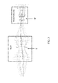
- FIG. 6 is a schematic diagram illustrating dynamic iris location options for a polarization-preserving stereoscopic system.
- a dynamic iris may be located at any or all of locations D and E, near the aperture stops or pupil positions of the relay and/or projection lenses. Such a dynamic iris may be, for example, an electro-mechanical iris with an adjustment response time on the order of a frame period.
- Other HDR modulators either global or pixelated, may be included in this system, at one or more of the locations A, B, and C, which may be positions between a pupil and field.
- a high resolution spatial light modulator may provide light to a relay lens system which may include a dynamic iris at location E. In some embodiments, the high resolution spatial light modulator may be a 4 K digital light processing projection system.
- the image impinging on the screen represents the superposition of light from the S and P paths of the XL unit. Assuming an unpolarized input, these images have very nearly the same amplitude. Since the eye averages the chrominance and luminance from each path, some compensation can be done to mitigate the voltage dependent color of the modulator. Assume, for example, that pi-cells are used as the modulator, which are zero-order variable retarders. If one path of the XL unit is given by a liquid crystal variable retarder between parallel polarizers, with the other given by a variable retarder between crossed polarizers, voltage lookup tables can be selected to mitigate chromatic effects. Note that the former has relatively low dynamic range in the half-wave state, but overall dynamic range may be sufficient for most applications.
- the terms “substantially” and “approximately” provide an industry-accepted tolerance for its corresponding term and/or relativity between items. Such an industry-accepted tolerance ranges from zero to ten percent and corresponds to, but is not limited to, component values, angles, et cetera. Such relativity between items ranges between approximately zero percent to ten percent.
Landscapes
- Physics & Mathematics (AREA)
- General Physics & Mathematics (AREA)
- Optics & Photonics (AREA)
- Engineering & Computer Science (AREA)
- Multimedia (AREA)
- Signal Processing (AREA)
- Transforming Electric Information Into Light Information (AREA)
- Projection Apparatus (AREA)
Abstract
Description
Claims (20)
Priority Applications (1)
| Application Number | Priority Date | Filing Date | Title |
|---|---|---|---|
| US15/151,376 US10097800B2 (en) | 2015-05-11 | 2016-05-10 | Optical lens systems with dynamic iris for modulating image frames |
Applications Claiming Priority (2)
| Application Number | Priority Date | Filing Date | Title |
|---|---|---|---|
| US201562159614P | 2015-05-11 | 2015-05-11 | |
| US15/151,376 US10097800B2 (en) | 2015-05-11 | 2016-05-10 | Optical lens systems with dynamic iris for modulating image frames |
Publications (2)
| Publication Number | Publication Date |
|---|---|
| US20160334696A1 US20160334696A1 (en) | 2016-11-17 |
| US10097800B2 true US10097800B2 (en) | 2018-10-09 |
Family
ID=57249494
Family Applications (1)
| Application Number | Title | Priority Date | Filing Date |
|---|---|---|---|
| US15/151,376 Active 2036-11-25 US10097800B2 (en) | 2015-05-11 | 2016-05-10 | Optical lens systems with dynamic iris for modulating image frames |
Country Status (2)
| Country | Link |
|---|---|
| US (1) | US10097800B2 (en) |
| WO (1) | WO2016183098A1 (en) |
Families Citing this family (3)
| Publication number | Priority date | Publication date | Assignee | Title |
|---|---|---|---|---|
| WO2017040530A1 (en) * | 2015-08-31 | 2017-03-09 | Reald Inc. | High dynamic range projection with multiple numerical aperture illumination |
| EP3367689A1 (en) * | 2017-02-24 | 2018-08-29 | Ymagis | Signal encoding and decoding for high contrast theatrical display |
| CN108628070B (en) * | 2017-03-23 | 2020-09-11 | 深圳光峰科技股份有限公司 | Display system |
Citations (14)
| Publication number | Priority date | Publication date | Assignee | Title |
|---|---|---|---|---|
| US5414460A (en) * | 1993-06-08 | 1995-05-09 | Eastman Kodak Company | Mechanical aperture for controlling illumination level |
| US20050270618A1 (en) | 2004-06-04 | 2005-12-08 | Seiko Epson Corporation | Image display apparatus, projector, and polarization compensation system |
| US7220006B2 (en) * | 2003-08-08 | 2007-05-22 | Allen Eddie E | Method and apparatus for increasing effective contrast ratio and brightness yields for digital light valve image projectors |
| US20070263179A1 (en) | 2005-06-21 | 2007-11-15 | Sony Corporation | Projection Type Display Unit |
| US20070279595A1 (en) | 2006-06-02 | 2007-12-06 | 3M Innovative Properties Company | Illumination system and projection system using same |
| JP2009265120A (en) | 2008-04-21 | 2009-11-12 | Sony Corp | Projection type display device |
| US20100097577A1 (en) * | 2008-10-20 | 2010-04-22 | Hon Hai Precision Industry Co., Ltd. | Dynamic aperture and projection device having same |
| US7857455B2 (en) | 2006-10-18 | 2010-12-28 | Reald Inc. | Combining P and S rays for bright stereoscopic projection |
| US7905602B2 (en) | 2006-09-29 | 2011-03-15 | Reald Inc. | Polarization conversion systems for stereoscopic projection |
| WO2013010167A2 (en) | 2011-07-14 | 2013-01-17 | Reald Inc. | Optical systems with compact back focal lengths |
| US8727536B2 (en) | 2007-05-09 | 2014-05-20 | Reald Inc. | Polarization conversion system and method for projecting polarization encoded imagery |
| US20150138508A1 (en) | 2013-11-15 | 2015-05-21 | Reald Inc. | High dynamic range, high contrast projection systems |
| US9244287B2 (en) | 2008-05-09 | 2016-01-26 | Reald Inc. | Optical systems with compact back focal lengths |
| US9854212B2 (en) * | 2015-08-31 | 2017-12-26 | Reald Inc. | High dynamic range projection with multiple numerical aperture illumination |
-
2016
- 2016-05-10 WO PCT/US2016/031669 patent/WO2016183098A1/en active Application Filing
- 2016-05-10 US US15/151,376 patent/US10097800B2/en active Active
Patent Citations (15)
| Publication number | Priority date | Publication date | Assignee | Title |
|---|---|---|---|---|
| US5414460A (en) * | 1993-06-08 | 1995-05-09 | Eastman Kodak Company | Mechanical aperture for controlling illumination level |
| US7220006B2 (en) * | 2003-08-08 | 2007-05-22 | Allen Eddie E | Method and apparatus for increasing effective contrast ratio and brightness yields for digital light valve image projectors |
| US20050270618A1 (en) | 2004-06-04 | 2005-12-08 | Seiko Epson Corporation | Image display apparatus, projector, and polarization compensation system |
| US20070263179A1 (en) | 2005-06-21 | 2007-11-15 | Sony Corporation | Projection Type Display Unit |
| US20070279595A1 (en) | 2006-06-02 | 2007-12-06 | 3M Innovative Properties Company | Illumination system and projection system using same |
| US7905602B2 (en) | 2006-09-29 | 2011-03-15 | Reald Inc. | Polarization conversion systems for stereoscopic projection |
| US7857455B2 (en) | 2006-10-18 | 2010-12-28 | Reald Inc. | Combining P and S rays for bright stereoscopic projection |
| US20140253879A1 (en) | 2007-05-09 | 2014-09-11 | Reald Inc. | Polarization conversion system and method for projecting polarization encoded imagery |
| US8727536B2 (en) | 2007-05-09 | 2014-05-20 | Reald Inc. | Polarization conversion system and method for projecting polarization encoded imagery |
| JP2009265120A (en) | 2008-04-21 | 2009-11-12 | Sony Corp | Projection type display device |
| US9244287B2 (en) | 2008-05-09 | 2016-01-26 | Reald Inc. | Optical systems with compact back focal lengths |
| US20100097577A1 (en) * | 2008-10-20 | 2010-04-22 | Hon Hai Precision Industry Co., Ltd. | Dynamic aperture and projection device having same |
| WO2013010167A2 (en) | 2011-07-14 | 2013-01-17 | Reald Inc. | Optical systems with compact back focal lengths |
| US20150138508A1 (en) | 2013-11-15 | 2015-05-21 | Reald Inc. | High dynamic range, high contrast projection systems |
| US9854212B2 (en) * | 2015-08-31 | 2017-12-26 | Reald Inc. | High dynamic range projection with multiple numerical aperture illumination |
Non-Patent Citations (5)
| Title |
|---|
| International search report and written opinion of international searching authority in co-pending PCT/US2016/031669, dated Jul. 27, 2016. |
| Murdoch et al., "Veiling glare and perceived black in high dynamic range displays", J. Opt. Soc. Am. A., vol. 29:4, Apr. 2012. |
| Pavlovych et al., "A High-Dynamic Range Projection System", Photonic Appl. in Biosensing and Imaging, SPIE vol. 6969, Sep. 2005. |
| Seetzen et al., "High dynamic range display systems", ACM Transactions on Graphics, 23:3, 2004. |
| Seetzen et al., "High dynamic range display using low and high resolution modulators", SID International Symposium Digest, 54:2, 2004. |
Also Published As
| Publication number | Publication date |
|---|---|
| WO2016183098A1 (en) | 2016-11-17 |
| US20160334696A1 (en) | 2016-11-17 |
Similar Documents
| Publication | Publication Date | Title |
|---|---|---|
| US9625745B2 (en) | High dynamic range, high contrast projection systems | |
| US11520164B2 (en) | Multi-focal display system and method | |
| US9971153B2 (en) | Method and apparatus for displaying video data | |
| US10983355B2 (en) | Method and system for occlusion capable compact displays | |
| US10536689B2 (en) | Projection display providing additional modulation and related methods | |
| US9854212B2 (en) | High dynamic range projection with multiple numerical aperture illumination | |
| KR20200009062A (en) | Multilayer High Dynamic Range Head Mounted Display | |
| JP2014509413A (en) | High contrast grayscale and color display | |
| US10097800B2 (en) | Optical lens systems with dynamic iris for modulating image frames | |
| KR101019378B1 (en) | High contrast stereoscopic projection system | |
| US11656466B2 (en) | Spatio-temporal multiplexed single panel based mutual occlusion capable head mounted display system and method | |
| US11503274B2 (en) | High speed binary compressive light field projection system | |
| Wetzstein et al. | Optical image processing using light modulation displays | |
| EP1701542B1 (en) | Optical system and image projection apparatus | |
| WO2009009416A2 (en) | Method and apparatus for reducing stereoscopic phase lag distortion under motion in a three-dimensional video display | |
| Zhang et al. | Add-on occlusion: Turning off-the-shelf optical see-through head-mounted displays occlusion-capable | |
| KR101453451B1 (en) | High Brightness Stereoscopic Projection Device Based on Phase Retardation and Operating Method For the Same | |
| Schuck et al. | 47.1: Invited Paper: 3D Digital Cinema Technologies |
Legal Events
| Date | Code | Title | Description |
|---|---|---|---|
| AS | Assignment |
Owner name: REALD INC., CALIFORNIA Free format text: ASSIGNMENT OF ASSIGNORS INTEREST;ASSIGNOR:SCHUCK, MILLER H.;REEL/FRAME:039401/0455 Effective date: 20160602 |
|
| STCF | Information on status: patent grant |
Free format text: PATENTED CASE |
|
| AS | Assignment |
Owner name: JEFFERIES FINANCE LLC, AS COLLATERAL AGENT, NEW YORK Free format text: SECURITY INTEREST;ASSIGNORS:REALD INC.;RHOMBUS INTERMEDIATE HOLDINGS, LP;REALD HOLDINGS, INC;AND OTHERS;REEL/FRAME:047723/0767 Effective date: 20181130 Owner name: JEFFERIES FINANCE LLC, AS COLLATERAL AGENT, NEW YO Free format text: SECURITY INTEREST;ASSIGNORS:REALD INC.;RHOMBUS INTERMEDIATE HOLDINGS, LP;REALD HOLDINGS, INC;AND OTHERS;REEL/FRAME:047723/0767 Effective date: 20181130 |
|
| AS | Assignment |
Owner name: JEFFERIES FINANCE LLC, AS COLLATERAL AGENT, NEW YORK Free format text: SECURITY INTEREST;ASSIGNORS:REALD INC.;RHOMBUS INTERMEDIATE HOLDINGS, LP;REALD HOLDINGS, INC;AND OTHERS;REEL/FRAME:047740/0085 Effective date: 20181130 Owner name: JEFFERIES FINANCE LLC, AS COLLATERAL AGENT, NEW YO Free format text: SECURITY INTEREST;ASSIGNORS:REALD INC.;RHOMBUS INTERMEDIATE HOLDINGS, LP;REALD HOLDINGS, INC;AND OTHERS;REEL/FRAME:047740/0085 Effective date: 20181130 |
|
| AS | Assignment |
Owner name: HPS INVESTMENT PARTNERS, LLC, AS THE SUCCESSOR-IN-INTEREST, NEW YORK Free format text: SECURITY INTEREST;ASSIGNOR:JEFFERIES FINANCE LLC, AS COLLATERAL AGENT;REEL/FRAME:052622/0104 Effective date: 20200506 Owner name: CORTLAND CAPITAL MARKET SERVICES LLC, AS THE SUCCESSOR COLLATERAL AGENT, ILLINOIS Free format text: ASSIGNMENT OF SECURITY INTEREST IN COLLATERAL;ASSIGNOR:JEFFERIES FINANCE LLC, AS COLLATERAL AGENT;REEL/FRAME:052623/0086 Effective date: 20200506 |
|
| AS | Assignment |
Owner name: COLORLINK, INC., CALIFORNIA Free format text: RELEASE OF SECURITY INTEREST RECORDED AT REEL/FRAME 047740/0085;ASSIGNOR:CORTLAND CAPITAL MARKET SERVICES, LLC;REEL/FRAME:054593/0247 Effective date: 20201120 Owner name: REALD DDMG ACQUISITION, LLC, CALIFORNIA Free format text: RELEASE OF SECURITY INTEREST RECORDED AT REEL/FRAME 047740/0085;ASSIGNOR:CORTLAND CAPITAL MARKET SERVICES, LLC;REEL/FRAME:054593/0247 Effective date: 20201120 Owner name: REALD SPARK, LLC, CALIFORNIA Free format text: RELEASE OF SECURITY INTEREST RECORDED AT REEL/FRAME 047740/0085;ASSIGNOR:CORTLAND CAPITAL MARKET SERVICES, LLC;REEL/FRAME:054593/0247 Effective date: 20201120 Owner name: RHOMBUS INTERMEDIATE HOLDINGS, LP, CALIFORNIA Free format text: RELEASE OF SECURITY INTEREST RECORDED AT REEL/FRAME 047740/0085;ASSIGNOR:CORTLAND CAPITAL MARKET SERVICES, LLC;REEL/FRAME:054593/0247 Effective date: 20201120 Owner name: REALD INC., CALIFORNIA Free format text: RELEASE OF SECURITY INTEREST RECORDED AT REEL/FRAME 047740/0085;ASSIGNOR:CORTLAND CAPITAL MARKET SERVICES, LLC;REEL/FRAME:054593/0247 Effective date: 20201120 |
|
| MAFP | Maintenance fee payment |
Free format text: PAYMENT OF MAINTENANCE FEE, 4TH YR, SMALL ENTITY (ORIGINAL EVENT CODE: M2551); ENTITY STATUS OF PATENT OWNER: SMALL ENTITY Year of fee payment: 4 |