US1009702A - Clutch. - Google Patents
Clutch. Download PDFInfo
- Publication number
- US1009702A US1009702A US59365310A US1910593653A US1009702A US 1009702 A US1009702 A US 1009702A US 59365310 A US59365310 A US 59365310A US 1910593653 A US1910593653 A US 1910593653A US 1009702 A US1009702 A US 1009702A
- Authority
- US
- United States
- Prior art keywords
- clutch
- shaft
- casing
- bearing
- transmission
- Prior art date
- Legal status (The legal status is an assumption and is not a legal conclusion. Google has not performed a legal analysis and makes no representation as to the accuracy of the status listed.)
- Expired - Lifetime
Links
Images
Classifications
-
- F—MECHANICAL ENGINEERING; LIGHTING; HEATING; WEAPONS; BLASTING
- F16—ENGINEERING ELEMENTS AND UNITS; GENERAL MEASURES FOR PRODUCING AND MAINTAINING EFFECTIVE FUNCTIONING OF MACHINES OR INSTALLATIONS; THERMAL INSULATION IN GENERAL
- F16D—COUPLINGS FOR TRANSMITTING ROTATION; CLUTCHES; BRAKES
- F16D13/00—Friction clutches
- F16D13/58—Details
- F16D13/70—Pressure members, e.g. pressure plates, for clutch-plates or lamellae; Guiding arrangements for pressure members
- F16D13/71—Pressure members, e.g. pressure plates, for clutch-plates or lamellae; Guiding arrangements for pressure members in which the clutching pressure is produced by springs only
-
- Y—GENERAL TAGGING OF NEW TECHNOLOGICAL DEVELOPMENTS; GENERAL TAGGING OF CROSS-SECTIONAL TECHNOLOGIES SPANNING OVER SEVERAL SECTIONS OF THE IPC; TECHNICAL SUBJECTS COVERED BY FORMER USPC CROSS-REFERENCE ART COLLECTIONS [XRACs] AND DIGESTS
- Y10—TECHNICAL SUBJECTS COVERED BY FORMER USPC
- Y10S—TECHNICAL SUBJECTS COVERED BY FORMER USPC CROSS-REFERENCE ART COLLECTIONS [XRACs] AND DIGESTS
- Y10S192/00—Clutches and power-stop control
- Y10S192/01—Removable members
-
- Y—GENERAL TAGGING OF NEW TECHNOLOGICAL DEVELOPMENTS; GENERAL TAGGING OF CROSS-SECTIONAL TECHNOLOGIES SPANNING OVER SEVERAL SECTIONS OF THE IPC; TECHNICAL SUBJECTS COVERED BY FORMER USPC CROSS-REFERENCE ART COLLECTIONS [XRACs] AND DIGESTS
- Y10—TECHNICAL SUBJECTS COVERED BY FORMER USPC
- Y10T—TECHNICAL SUBJECTS COVERED BY FORMER US CLASSIFICATION
- Y10T74/00—Machine element or mechanism
- Y10T74/20—Control lever and linkage systems
- Y10T74/20396—Hand operated
Definitions
- WITNEfiSES set forth and mo e particularly pointed out PATENT orrron.
- his invention relates to improvements in clutches and more particularly to those of- -the friction disk type especially adapted for automobile use.
- 1 is the for ward portion of the casing for a variable speed mechanism, in which casing is mounted a tubular shaft l-forming a part of the variable speed mechanism, the remainder of which is not shown.
- a clutch casing 3 is .detachably secured in any suitable manner to the end of the transmission casing, as by bolts 4 passing through meeting flanges on the ends of the two casings.
- a drain?) is formed with a hub 6 keyed or otherwise sccured upon the forward end of the shaft 2 to turn therewith and a series of friction rings 7 is carried within the drum and connected thereto to turn therewith by lugs S on the rings engagin longitudinal grooves 9 in the inner face -0 the outer wall of the drum.
- An anti friction end thrust bearing 10 of any preferred type is secured in the forward end of the casing-3 in axial alinemcnt with the shaft 2 'by a removable collar 11 secured against theend of the casing by cap screws 12 or the like.
- a clutch shaft 13 is journaled in axial alinernent with the shaft 2 within the bearing 10 with its forward end stepped in the forward end of said tubular shaft with a bearing sleeve interposed, 'if desired.
- the forward end of the clutch -shaft which extends forwardly from the bearing 10 is squared, splined or otherwise fashioned to enga e the hub'15 of one yoke 14 of a universa joint for connecting ashaft (not shown) to the forward end of the clutch shaft 13.
- the hub 15 of the yoke serves the purpose of a thrust collar opposing a shoulder formed .by reducing the diameter of the shaft and coacts with said shoulder to prevent longitudinal shifting of the shaft in the bearing 10.
- a spider 16 is secured upon the shaft 13 toturn therewith within the drum 5 and friction disks 17 alternating with the rings 7 are carried'upon the periphery of the spider and attached thereto to turn therewith, said disks being held from slipping longitudinally from the rear end of the spider byfan end flange 18 on said spider.
- a collar 19 is formed with a hub; portion 20 fitting the shaft'13 and adapted to slide longitudinally thereon and is also provide with a rim portion projecting into the drum outside of'the spider and having a flange 21 to engage the foremost disk or. ring.
- the spider is formed with.
- a two I part ring 25 is secured together by cap screws 26 about the hub 20 of the slide collar against an .end llange 24 on said hub, and this ring is provided with diametrically disposed studs 27 engaged withope'nings 1n the ends of-the arms of a yoke 28.
- Said yoke has a split hub 29 within which stub shafts 30 are secured, and these stub shafts are adapted to rock in suitable bearing sockets in the casing 3, one of said shafts being 4 working through into the clutch casing and :ing. pedal or. lever 32 thereto.
- the entire clutch 'meclianism including its casing and operatinsures r0 'er workin of the clutch.
- the casing in thefront end thereof, of a extended through its bearing and provided with the transmission shaft, coupling means vshaft, a'drlthi with a key 31 for securing a suitable operating lever may be very quickly detached'and bodily removed as a: unit by removing the bolts 4. and disconnecting'the yoke 14 of the universal joint fromthe other parts of said joint.
- the clutch drumand shaft may on the front end of the clutc v in the clutch casing attached to the tra'iismission shaft to turn therewith, a spider f secured upon the clutch shaft.
- variable speed transmission mechanism comprising a' casf ingandazshaft in said casing, of a clutch casing dctachably secured to the end of the transmission'casing atone end and provided with abearing at its opposite end in alinesaid bearing, means on theouterend of said a drum detachably secured turn-I therewith, and multiple friction disk mechanism within said drum for connecting "2:.
- the combination with a variablespeed transmision mechanism comprising .9. casing-and.
- variable speed transmission mechanism comprising a casing and, a shaft extending longitudinally of clutch casingfhavingan open rear end detachably secured to the said transmission casing,- said transmission casing formin the sole support fox-said clutch casing, a aring in the front end of said clutch casing in alinemetit with the transmission shaft, a clutch shaft insaidgbearing in alinement 4.
- friction rings havin lu s tee a sai I grooves and slidable free ly M a spider on the clutch shaftawithiii-tht; drum, friction disks on the spider connect; ed thereto to'turn therewith and'alte rnating,
- the combination with variable speed transmission mechanism comprising a casing having a bearing in its front end and a shaft in said bearing projecting. therethrough, of a clutch casing secured at itsv rear end tothe forward end of the trans-'- mission casing, an anti-friction bearing in the frontend of the clutch. casing aimed withlthe'transmis'sion shaft, a clutch shaft stepped at one end in the transmission shaft and journaled in said bearing, said clutch shaft being reduced. at. its forward, end to form a shoulder thereon to engage the said bearing, a member of a universal joint having a hub engaging and securedupon the outer end of the clutch shaft and adapted- .to co-actfwith-said shoulder on the. clutch.
Description
J. G. UTZ.
CLUTCH.
APPLICATION FILED NOV. 22, 1910.
1,009,702. Patented Nov. 21, 1911 2 $HEETS-SHEET 1.
ammwmp 5cm wc;
J. G. UTZ.
CLUTCH.
APPLIGATION FILED N0v.22.1910.
1,009,702. Patented Nov. 21, 1911.
2 SHBETS-SHEET 2 'IIJIIIIIIIIIIIA INVENTOR'.
WITNEfiSES set forth and mo e particularly pointed out PATENT orrron.
JOHN G. UTZ, 0F DETROIT, MICHIGAN.
CLUTCH.'-
Specification of Letters Patent. Patented Nov. 21, 1911.
Application filed November 22, 1910. Serial 593,653.
Toiall whom it may concert: Be it known that I, Jomv G. U'rz, a'citizen of the United States of America, residing at Detroit; in the county of Vayne and State -of Michigan, have invented certain new and useful Improvements in Clutches, of which the following is a specification, reference being had therein to the accompanyin' drawings, I 1
. his invention relates to improvements in clutches and more particularly to those of- -the friction disk type especially adapted for automobile use. Y
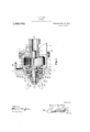
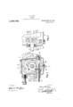
The object of theinventionis to'lprovl de an arrangement-of parts whereby the device may be easilyffdismounted and removed as a unit for the purpose ,ofinspection or repair and to provide certain other new and useful featuresi-in the construction, the invention consisting in the matters hereinafter in the appended claims, reference being had J to the accompanying drawings, in which lqigure 1 isa-view in longitudinalzis'ection of a clutch embodying the invention toget-her with portions of a variable speed mechanism Fig. 2l;is.a transverse section of the same on thelline w'w; and Fig. 3 is adetail showing a. portion of the front end .of the device in section substantially upon the line y--- 1 of Fig. 2.
As shown in the drawings, 1 is the for ward portion of the casing for a variable speed mechanism, in which casing is mounted a tubular shaft l-forming a part of the variable speed mechanism, the remainder of which is not shown. A clutch casing 3 is .detachably secured in any suitable manner to the end of the transmission casing, as by bolts 4 passing through meeting flanges on the ends of the two casings. A drain?) is formed with a hub 6 keyed or otherwise sccured upon the forward end of the shaft 2 to turn therewith and a series of friction rings 7 is carried within the drum and connected thereto to turn therewith by lugs S on the rings engagin longitudinal grooves 9 in the inner face -0 the outer wall of the drum.
An anti friction end thrust bearing 10 of any preferred type is secured in the forward end of the casing-3 in axial alinemcnt with the shaft 2 'by a removable collar 11 secured against theend of the casing by cap screws 12 or the like. A clutch shaft 13 is journaled in axial alinernent with the shaft 2 within the bearing 10 with its forward end stepped in the forward end of said tubular shaft with a bearing sleeve interposed, 'if desired. The forward end of the clutch -shaft which extends forwardly from the bearing 10 is squared, splined or otherwise fashioned to enga e the hub'15 of one yoke 14 of a universa joint for connecting ashaft (not shown) to the forward end of the clutch shaft 13. The hub 15 of the yoke serves the purpose of a thrust collar opposing a shoulder formed .by reducing the diameter of the shaft and coacts with said shoulder to prevent longitudinal shifting of the shaft in the bearing 10. a
A spider 16 is secured upon the shaft 13 toturn therewith within the drum 5 and friction disks 17 alternating with the rings 7 are carried'upon the periphery of the spider and attached thereto to turn therewith, said disks being held from slipping longitudinally from the rear end of the spider byfan end flange 18 on said spider. A collar 19 is formed with a hub; portion 20 fitting the shaft'13 and adapted to slide longitudinally thereon and is also provide with a rim portion projecting into the drum outside of'the spider and having a flange 21 to engage the foremost disk or. ring. The spider is formed with. a series of pockets open at their rear ends and bolts or plungers'QQ having heads at one end are secured at their opposite ends to the collars 19 and pass freely through holes in the bottom of tiou rings and disks into frictional engage ment to cause the drum. and spider to.turn
together. To move the collar 19 longitudinally againstthe action of said springs 23 and take the pressure off from the .disks and rings so that the drum may-turn independently of the spider and its shaftl3, a two I part ring 25 is secured together by cap screws 26 about the hub 20 of the slide collar against an .end llange 24 on said hub, and this ring is provided with diametrically disposed studs 27 engaged withope'nings 1n the ends of-the arms of a yoke 28. Said yoke has a split hub 29 within which stub shafts 30 are secured, and these stub shafts are adapted to rock in suitable bearing sockets in the casing 3, one of said shafts being 4 working through into the clutch casing and :ing. pedal or. lever 32 thereto. In this construction the entire clutch 'meclianism," including its casing and operatinsures r0 'er workin of the clutch.
meat with said transmission shaft, a clutch shaft stepped in the end" of said transmis-- 'sion shaft atone end and projecting through 30 clutchshaftffor detachably attaching-ha f shaft thereto,
'upon' -thej end of the transmission shaft' tosaid 'drum a nd clutch shaft to cause them totum together.
"in the endlof the transmission shaft and exoint member. secured upon the front end of mechanism. I
'the casing in thefront end thereof, of a extended through its bearing and provided with the transmission shaft, coupling means vshaft, a'drlthi with a key 31 for securing a suitable operating lever, may be very quickly detached'and bodily removed as a: unit by removing the bolts 4. and disconnecting'the yoke 14 of the universal joint fromthe other parts of said joint. 'The clutch drumand shaft may on the front end of the clutc v in the clutch casing attached to the tra'iismission shaft to turn therewith, a spider f secured upon the clutch shaft. .friction disks carried by the spider and operatively connected thereto to .turntherewith, friction rings alternating with the friction disks and slidable into and connected to the drum to turn therewith, said spider and friction then be withdrawn from engagement with disks and rings beinginclosed within the struction; of bearing for the transmission,
, the end of the transmission shaft 2 without drum and removable ldngitudinally t-hereaffecting the adjustment of the parts of the clutch mechanism. The particular coning is detached from the transmission casing, and means forv forcing the disks and and clutch shafts also prevents oil from "rings into frictional contactlwith each other.
Havin t us'fully described my invention whatjI c aim is:. i
1. The combination with a variable speed transmission mechanism comprising a' casf ingandazshaft in said casing, of a clutch casing dctachably secured to the end of the transmission'casing atone end and provided with abearing at its opposite end in alinesaid bearing, means on theouterend of said a drum detachably secured turn-I therewith, and multiple friction disk mechanism within said drum for connecting "2:. The combination with a variablespeed transmision mechanism comprising .9. casing-and. a: shaft in said casin projecting forwardly't-herefrom, of a clutc 1 casing detachably'securedato the front end of said transmission casing and supported thereby, a bearin in thefront end of the clutch casing, a-c utch shaft stepped at its rear end tending through said bearing, a universal the clutch shaft, multiple friction disk mechanism within the clutch casing for connecting the transmission shaft and the clutch shaft, and means carried by the clutch casing for operating the friction disk 3. The combination with a variable speed transmission mechanism comprising a casing and, a shaft extending longitudinally of clutch casingfhavingan open rear end detachably secured to the said transmission casing,- said transmission casing formin the sole support fox-said clutch casing, a aring in the front end of said clutch casing in alinemetit with the transmission shaft, a clutch shaft insaidgbearing in alinement 4. The combination with a variable speed ing and a shaft extending longitudinally of the casing through Zthe front end thereof, of a clutch casing detachablysecuredtd the front end of the transmission casing, a
clutch shaft mountedfin the clutch casing in alinementwith the transmission shaft and extending through the frontend of said cas ing, a coupling-member in the-frontend of said clutch shaft,';ajdrumiwithin thel'clutch casingsecured upon: the projecti I the transmission shaftiand provi ed with grooves in the inner face ants" outerwall" e. drum,
friction rings havin lu s tee a sai I grooves and slidable free ly M a spider on the clutch shaftawithiii-tht; drum, friction disks on the spider connect; ed thereto to'turn therewith and'alte rnating,
with said friction rings, means forretaining thedi'sks'upon the spider-with the rings. between them, a collar slidable upon the'clutch shaft provided with a peripheral portion'extending into the drum to' engagethe'ad'a cent disk; springs carried the" noving the collar to clamp thej'rmgs' and disks between it and the said" retaining. means on the s'pider,-and means on the clutch casing for moving the collar against the action of said springs. I
5. The combination with variable speed transmission mechanism comprising a casing having a bearing in its front end and a shaft in said bearing projecting. therethrough, of a clutch casing secured at itsv rear end tothe forward end of the trans-'- mission casing, an anti-friction bearing in the frontend of the clutch. casing aimed withlthe'transmis'sion shaft, a clutch shaft stepped at one end in the transmission shaft and journaled in said bearing, said clutch shaft being reduced. at. its forward, end to form a shoulder thereon to engage the said bearing, a member of a universal joint having a hub engaging and securedupon the outer end of the clutch shaft and adapted- .to co-actfwith-said shoulder on the. clutch.
shaft to hold said shaft in place withinsaid bearing, a forwardly open drum within the ider or I
Priority Applications (1)
| Application Number | Priority Date | Filing Date | Title |
|---|---|---|---|
| US59365310A US1009702A (en) | 1910-11-22 | 1910-11-22 | Clutch. |
Applications Claiming Priority (1)
| Application Number | Priority Date | Filing Date | Title |
|---|---|---|---|
| US59365310A US1009702A (en) | 1910-11-22 | 1910-11-22 | Clutch. |
Publications (1)
| Publication Number | Publication Date |
|---|---|
| US1009702A true US1009702A (en) | 1911-11-21 |
Family
ID=3078012
Family Applications (1)
| Application Number | Title | Priority Date | Filing Date |
|---|---|---|---|
| US59365310A Expired - Lifetime US1009702A (en) | 1910-11-22 | 1910-11-22 | Clutch. |
Country Status (1)
| Country | Link |
|---|---|
| US (1) | US1009702A (en) |
Cited By (4)
| Publication number | Priority date | Publication date | Assignee | Title |
|---|---|---|---|---|
| US2632543A (en) * | 1947-04-04 | 1953-03-24 | Allis Chalmers Mfg Co | Clutch installation for motor vehicles |
| US3263521A (en) * | 1962-01-31 | 1966-08-02 | Daimler Benz Ag | Transmission housing |
| US5186573A (en) * | 1991-09-23 | 1993-02-16 | Dana Corporation | Coupling for connecting shafts |
| US5322148A (en) * | 1993-08-09 | 1994-06-21 | Fernandez Robert A | Adapter kit for a clutch |
-
1910
- 1910-11-22 US US59365310A patent/US1009702A/en not_active Expired - Lifetime
Cited By (4)
| Publication number | Priority date | Publication date | Assignee | Title |
|---|---|---|---|---|
| US2632543A (en) * | 1947-04-04 | 1953-03-24 | Allis Chalmers Mfg Co | Clutch installation for motor vehicles |
| US3263521A (en) * | 1962-01-31 | 1966-08-02 | Daimler Benz Ag | Transmission housing |
| US5186573A (en) * | 1991-09-23 | 1993-02-16 | Dana Corporation | Coupling for connecting shafts |
| US5322148A (en) * | 1993-08-09 | 1994-06-21 | Fernandez Robert A | Adapter kit for a clutch |
Similar Documents
| Publication | Publication Date | Title |
|---|---|---|
| US3176813A (en) | Centrifugally actuated fluid clutch | |
| US2057802A (en) | Clutch | |
| US2002841A (en) | Clutch | |
| US1009702A (en) | Clutch. | |
| US2935169A (en) | Disengaging spring means for fluid clutches | |
| US3563114A (en) | Forward and reverse planetary gearing | |
| US2019745A (en) | Transmission mechanism | |
| US2289019A (en) | Hydraulic coupling with neutral and dual locking means therefor | |
| US1689245A (en) | Powee transmitter | |
| US1099509A (en) | Friction-clutch. | |
| US3068979A (en) | Propeller shaft slip joint | |
| US3142195A (en) | Transmission | |
| US1702000A (en) | Clutch-lining arrangement | |
| US1665554A (en) | Clutch | |
| US2320116A (en) | Power transmission mechanism | |
| US1460217A (en) | Clutch | |
| US1164531A (en) | Clutch. | |
| US1469564A (en) | Friction clutch | |
| US1703788A (en) | Clutch | |
| US1171341A (en) | Clutch mechanism. | |
| US1352251A (en) | Flexible coupling | |
| US2182407A (en) | Motor vehicle power transmission | |
| US2285652A (en) | Clutch | |
| US2064499A (en) | Clutch | |
| US1092015A (en) | Automobile-clutch. |