US10094877B2 - Method and apparatus for determining presence and operation of components in a printed circuit board - Google Patents
Method and apparatus for determining presence and operation of components in a printed circuit board Download PDFInfo
- Publication number
- US10094877B2 US10094877B2 US15/677,694 US201715677694A US10094877B2 US 10094877 B2 US10094877 B2 US 10094877B2 US 201715677694 A US201715677694 A US 201715677694A US 10094877 B2 US10094877 B2 US 10094877B2
- Authority
- US
- United States
- Prior art keywords
- sensor
- color
- led
- components
- component
- Prior art date
- Legal status (The legal status is an assumption and is not a legal conclusion. Google has not performed a legal analysis and makes no representation as to the accuracy of the status listed.)
- Active
Links
- 238000000034 method Methods 0.000 title claims abstract description 45
- 238000012360 testing method Methods 0.000 claims description 23
- 238000005070 sampling Methods 0.000 claims description 19
- 239000000835 fiber Substances 0.000 claims description 9
- 238000001914 filtration Methods 0.000 claims 1
- 239000000523 sample Substances 0.000 description 38
- 239000003086 colorant Substances 0.000 description 9
- 230000008569 process Effects 0.000 description 8
- 238000012795 verification Methods 0.000 description 8
- 238000005259 measurement Methods 0.000 description 5
- 239000011159 matrix material Substances 0.000 description 4
- 239000003990 capacitor Substances 0.000 description 3
- 230000008901 benefit Effects 0.000 description 2
- 238000009434 installation Methods 0.000 description 2
- 238000012986 modification Methods 0.000 description 2
- 230000004048 modification Effects 0.000 description 2
- 230000003287 optical effect Effects 0.000 description 2
- 230000008859 change Effects 0.000 description 1
- 230000001419 dependent effect Effects 0.000 description 1
- 230000000977 initiatory effect Effects 0.000 description 1
- 238000012545 processing Methods 0.000 description 1
- 230000004044 response Effects 0.000 description 1
- 230000000630 rising effect Effects 0.000 description 1
- 230000001960 triggered effect Effects 0.000 description 1
Images


Classifications
-
- G—PHYSICS
- G01—MEASURING; TESTING
- G01R—MEASURING ELECTRIC VARIABLES; MEASURING MAGNETIC VARIABLES
- G01R31/00—Arrangements for testing electric properties; Arrangements for locating electric faults; Arrangements for electrical testing characterised by what is being tested not provided for elsewhere
- G01R31/28—Testing of electronic circuits, e.g. by signal tracer
- G01R31/317—Testing of digital circuits
- G01R31/31728—Optical aspects, e.g. opto-electronics used for testing, optical signal transmission for testing electronic circuits, electro-optic components to be tested in combination with electronic circuits, measuring light emission of digital circuits
-
- G—PHYSICS
- G01—MEASURING; TESTING
- G01J—MEASUREMENT OF INTENSITY, VELOCITY, SPECTRAL CONTENT, POLARISATION, PHASE OR PULSE CHARACTERISTICS OF INFRARED, VISIBLE OR ULTRAVIOLET LIGHT; COLORIMETRY; RADIATION PYROMETRY
- G01J1/00—Photometry, e.g. photographic exposure meter
- G01J1/02—Details
- G01J1/0204—Compact construction
-
- G—PHYSICS
- G01—MEASURING; TESTING
- G01J—MEASUREMENT OF INTENSITY, VELOCITY, SPECTRAL CONTENT, POLARISATION, PHASE OR PULSE CHARACTERISTICS OF INFRARED, VISIBLE OR ULTRAVIOLET LIGHT; COLORIMETRY; RADIATION PYROMETRY
- G01J1/00—Photometry, e.g. photographic exposure meter
- G01J1/02—Details
- G01J1/0228—Control of working procedures; Failure detection; Spectral bandwidth calculation
-
- G—PHYSICS
- G01—MEASURING; TESTING
- G01J—MEASUREMENT OF INTENSITY, VELOCITY, SPECTRAL CONTENT, POLARISATION, PHASE OR PULSE CHARACTERISTICS OF INFRARED, VISIBLE OR ULTRAVIOLET LIGHT; COLORIMETRY; RADIATION PYROMETRY
- G01J1/00—Photometry, e.g. photographic exposure meter
- G01J1/02—Details
- G01J1/04—Optical or mechanical part supplementary adjustable parts
- G01J1/0488—Optical or mechanical part supplementary adjustable parts with spectral filtering
- G01J1/0492—Optical or mechanical part supplementary adjustable parts with spectral filtering using at least two different filters
-
- G—PHYSICS
- G01—MEASURING; TESTING
- G01J—MEASUREMENT OF INTENSITY, VELOCITY, SPECTRAL CONTENT, POLARISATION, PHASE OR PULSE CHARACTERISTICS OF INFRARED, VISIBLE OR ULTRAVIOLET LIGHT; COLORIMETRY; RADIATION PYROMETRY
- G01J1/00—Photometry, e.g. photographic exposure meter
- G01J1/42—Photometry, e.g. photographic exposure meter using electric radiation detectors
- G01J1/4204—Photometry, e.g. photographic exposure meter using electric radiation detectors with determination of ambient light
-
- G—PHYSICS
- G01—MEASURING; TESTING
- G01J—MEASUREMENT OF INTENSITY, VELOCITY, SPECTRAL CONTENT, POLARISATION, PHASE OR PULSE CHARACTERISTICS OF INFRARED, VISIBLE OR ULTRAVIOLET LIGHT; COLORIMETRY; RADIATION PYROMETRY
- G01J1/00—Photometry, e.g. photographic exposure meter
- G01J1/42—Photometry, e.g. photographic exposure meter using electric radiation detectors
- G01J1/44—Electric circuits
-
- G—PHYSICS
- G01—MEASURING; TESTING
- G01J—MEASUREMENT OF INTENSITY, VELOCITY, SPECTRAL CONTENT, POLARISATION, PHASE OR PULSE CHARACTERISTICS OF INFRARED, VISIBLE OR ULTRAVIOLET LIGHT; COLORIMETRY; RADIATION PYROMETRY
- G01J3/00—Spectrometry; Spectrophotometry; Monochromators; Measuring colours
- G01J3/02—Details
- G01J3/0264—Electrical interface; User interface
-
- G—PHYSICS
- G01—MEASURING; TESTING
- G01J—MEASUREMENT OF INTENSITY, VELOCITY, SPECTRAL CONTENT, POLARISATION, PHASE OR PULSE CHARACTERISTICS OF INFRARED, VISIBLE OR ULTRAVIOLET LIGHT; COLORIMETRY; RADIATION PYROMETRY
- G01J3/00—Spectrometry; Spectrophotometry; Monochromators; Measuring colours
- G01J3/46—Measurement of colour; Colour measuring devices, e.g. colorimeters
- G01J3/50—Measurement of colour; Colour measuring devices, e.g. colorimeters using electric radiation detectors
- G01J3/505—Measurement of colour; Colour measuring devices, e.g. colorimeters using electric radiation detectors measuring the colour produced by lighting fixtures other than screens, monitors, displays or CRTs
-
- G—PHYSICS
- G01—MEASURING; TESTING
- G01J—MEASUREMENT OF INTENSITY, VELOCITY, SPECTRAL CONTENT, POLARISATION, PHASE OR PULSE CHARACTERISTICS OF INFRARED, VISIBLE OR ULTRAVIOLET LIGHT; COLORIMETRY; RADIATION PYROMETRY
- G01J3/00—Spectrometry; Spectrophotometry; Monochromators; Measuring colours
- G01J3/46—Measurement of colour; Colour measuring devices, e.g. colorimeters
- G01J3/50—Measurement of colour; Colour measuring devices, e.g. colorimeters using electric radiation detectors
- G01J3/51—Measurement of colour; Colour measuring devices, e.g. colorimeters using electric radiation detectors using colour filters
- G01J3/513—Measurement of colour; Colour measuring devices, e.g. colorimeters using electric radiation detectors using colour filters having fixed filter-detector pairs
-
- G—PHYSICS
- G01—MEASURING; TESTING
- G01J—MEASUREMENT OF INTENSITY, VELOCITY, SPECTRAL CONTENT, POLARISATION, PHASE OR PULSE CHARACTERISTICS OF INFRARED, VISIBLE OR ULTRAVIOLET LIGHT; COLORIMETRY; RADIATION PYROMETRY
- G01J1/00—Photometry, e.g. photographic exposure meter
- G01J1/42—Photometry, e.g. photographic exposure meter using electric radiation detectors
- G01J2001/4247—Photometry, e.g. photographic exposure meter using electric radiation detectors for testing lamps or other light sources
- G01J2001/4252—Photometry, e.g. photographic exposure meter using electric radiation detectors for testing lamps or other light sources for testing LED's
Definitions
- This invention relates to a method and apparatus for testing for the presence, brightness and/or color of components in a printed circuit board, where the components are biased either with constant current or with a current pulse.
- Printed circuit boards typically contain multiple components including: light emitting diodes (LEDs), resistors, capacitors, diodes, fuses, processors, and similar such components.
- LEDs light emitting diodes
- resistors resistors
- capacitors diodes
- diodes diodes
- processors and similar such components.
- verification of the presence of such components in a printed circuit board required powering up a fully rendered printed circuit board and manually verifying the presence of the correct components.
- a test fixture may be constructed including bulky and expensive fiber optics that extend between the printed circuit board to be tested and a test system.
- Verification of the presence and operation of LEDs within a printed circuit board may be accomplished without a power supply such as described in U.S. Pat. No. 6,490,037, issued to Schmitt, which is hereby incorporated by reference in its entirety in a manner consistent with the present document. Further, verification of the presence and operation of LEDs within a printed circuit board may be accomplished such as described in U.S. Pat. Nos. 7,023,554; 7,227,639; and 7,265,822, each issued to Schmitt, which are also each hereby incorporated by reference in their entirety in a manner consistent with the present document. However, these known methods require a constant current for a sampling period.
- Determination of the color and brightness of the components include LEDs, beyond mere verification, typically requires extensive calibration and set-up to align sensors with the components and run the wiring necessary for sending numerous signals to determine such parameters of the components.
- a method and apparatus for determination of presence, brightness and/or color of components in a printed circuit board eliminates much of the time-consuming and costly procedures required by manual determination and the equally costly test fixtures requiring time-intensive and complex set-up and calibration.
- the following description will primarily refer to LEDs however other components may be used with the method and apparatus of this invention.
- the method and apparatus of this invention allows for testing for the presence, brightness and/or color of an LED in a printed circuit board, where the LED is biased with a constant current or with a current pulse while avoiding the time-consuming and costly procedures of previously known methods.
- the apparatus preferably includes an enclosure module device that includes multiple sensors attached to fiber optic cables having a plurality of color receptors in a simple, easy to mount assembly.
- the device for determining at least one of a presence, a brightness and a color of components in printed circuit board preferably includes the sensors arranged within a housing or similar structure, hereinafter referred as module.
- An input of the module may comprise either a USB or a serial connection.
- a command is provided to the module through a USB or serial cable, the module then samples a requested color sensor attached to fiber optic cables.
- the module sends back a color and/or an intensity reading back via the USB or the serial connection.
- the module will also update output pins with proper frequency (in Hz) and voltage (in volts) readings for component color and a voltage reading for the component intensity.
- FIG. 1 is a schematic front view of a sensor according to one preferred embodiment of this invention.
- FIG. 2 is a schematic rear view of the sensor shown in FIG. 1 .
- FIG. 3 is a diagrammatic perspective front view of a portion of a test fixture according to one preferred embodiment of this invention.
- FIG. 4 is a schematic of test apparatus according to one preferred embodiment of this invention.
- FIG. 5 is a flow chart of the operation of a device according to one preferred embodiment of this invention.
- FIG. 6 is a schematic top side view of a sensor according to another preferred embodiment of this invention.
- FIG. 7 is a schematic bottom side view of the sensor shown in FIG. 6 .
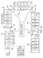
- FIG. 8 is schematic representation of enclosure module according to an embodiment of this invention for testing a plurality of components.
- FIG. 9 is a schematic representation of a sensor board according to an embodiment of this invention.
- FIG. 10 is a schematic representation of enclosure modules connected in a daisy chain configuration.
- DC Mode constant current
- Pulsing Mode current pulses
- LEDs 15 are typically used in printed circuit boards 90 and require verification and determination of their operation in a different manner than the traditional manner of verification of the placement and operation of integrated circuits within printed circuit board 90 .
- LEDs 15 are available in clear/white and several common colors such as red, green and blue. Beyond mere verification of the operation of LED 15 , it is also preferable, and an object of this invention, to determine the color and brightness of LED 15 , in part to confirm that such LED is in the desired position in printed circuit board 90 and functions as intended.
- the apparatus includes sensor 10 .
- sensor 10 comprises an assembly of components that may be used in connection with test systems and test fixtures for quickly and accurately determining a color and brightness of LED 15 .
- the sensor 10 otherwise known as a MEGA FINNTM sensor, is preferably positioned in physical proximity to LED 15 to be tested.
- the sensor preferably includes a plurality of color receptors having different colors. The intensity of the detected light is related to the color of the object. An output signal from the device is thus proportional to the reflected light.
- the sensor 10 preferably includes a plurality of filters 20 arranged in a matrix.
- Each filter 20 is preferably a discrete optical filter or color receptor which permits only light in a range about the target wavelength of the color to be detected to pass.
- each filter 20 is preferably designed to detect a certain range of color, e.g. blue, red, green and/or clear.
- the plurality of filters 20 preferably include: a plurality of clear receptors 23 ; a plurality of red receptors 25 ; a plurality of blue receptors 27 ; and/or a plurality of green receptors 30 .
- the sensor 10 of this invention is not limited to these colors.
- the different color receptors 23 , 25 , 27 and 30 are interspersed within the matrix.
- An example of such a filter 20 is manufactured by AMS-TAOS Inc. of Plano, Tex., part number TCS 3200.
- sensor 10 includes a minimum amount of connections, or probes, to minimize the necessary set-up and installation of sensor 10 .
- sensor 10 preferably includes three probes, specifically, output probe 40 , input probe 50 and ground probe 60 .
- Output probe 40 is preferably connected to sensor 10 and provides a color output and a brightness output in a single signal.
- this single signal is made possible by a method of operation described in more detail below. Such single signal through a single output probe 40 thereby simplifies the connections necessary to connect sensor 10 relative to LED 15 within the test system.
- Input probe 50 is preferably connected to the sensor and provides power to sensor 10 from an external power source. Input probe 50 preferably accommodates an operating voltage between approximately 2.7 Vdc and 5.5 Vdc. Input probe 50 may draw power directly from a digital output.
- Ground probe 60 is preferably additionally connected to sensor 10 and is connected to an external ground.
- microprocessor 70 is preferably connected between filters 20 and output probe 40 and calculates the color and the brightness of LED 15 .
- Microprocessor 70 may be programmable to permit modifications of sensor 10 based upon variables within the system to be tested such as LEDs 15 having atypical colors, brightness, positions, ambient conditions and other parameters that may require customization and/or programming of microprocessor 70 .
- probes 40 , 50 and/or 60 each may configured in a straight path, may each include a 90° bend, may be pre-formed into other configurations and/or may be bendable to permit forming into suitable configurations.
- sensor 10 preferably further includes an oscillator 75 that provides fast speed, higher accuracy and response times allowing the sensor 10 quickly take samples, such as when the LED 15 is biased with a current pulse.
- the oscillator 75 may comprise an external oscillator.
- the oscillator 75 connects to a processor 70 allowing the processor 70 to run at much faster speed and make faster and more accurate measurements of the color sensor.
- the sensor 10 of this invention is able to detect changes in light, such as from a fast pulsing LED, and make quick and intelligent decisions on how to measure the sensor. Since the light from a pulsing LED is constantly changing the processor 70 needs to keep with fast and accurate measurement and also make fast calculation to find out the color of the light.
- the oscillator also allows the sensor 10 to operate with an Auto Triggering feature. When the light changes, the sensor 10 is able to quickly detect this change and auto trigger the processor 70 to start a fresh sample quickly and measure accurately.
- the senor 10 further includes a fuse and diodes to protect the sensor from overpowering and/or reverse wiring.
- a color and a brightness of LED 15 is thereby determined with microprocessor 70 connected with respect to sensor 10 and a single output signal is sent from sensor 10 to some form of operator interface, such as a multimeter, a voltmeter, a counter or similar measuring device known to those having ordinary skill in the art.
- a color and brightness of LED 15 may be determined by sampling the output of LED 15 for a period of time. The period of time may be dependent upon the brightness of LED 15 and/or the color of LED 15 .
- a count for each color receptor 23 , 25 , 27 and/or 30 is then determined based upon the given period of time.
- a sample or count across each color receptor 23 , 25 , 27 and/or 30 is then compared to determine the color of LED 15 .
- sensor 10 sequentially compares the count for clear receptor 23 with the count for red receptor 25 with the count for blue receptor 27 with the count for green receptor 30 so that the count for each color receptor is compared with the count of each other color receptor. Comparison of the counts for each filter 20 thereby yields a wavelength and, thus, the color of LED 15 .
- the following table provides typical measurements for various colors of particular LEDs 15 .
- the wavelength of the color is converted to a frequency.
- a relationship of the count relative to the frequency of the single output signal is then calculated to determine the color of LED 15 .
- the frequency is further encoded with a pulse width and a DC average of the pulse width is measured to obtain the brightness of LED 15 .
- sensor 10 may additionally detect white light and provide a signal indicating the presence of a broad range of colors in the light and/or the brightness of white light. If a dominant color is present within the white light, sensor 10 will preferably indicate such dominant color within the single output signal.
- a method for determining a color and brightness of LED 15 may be used in connection with printed circuit board 90 having a plurality of LEDs 15 .
- a corresponding plurality of sensors 10 may thereby be positioned on test fixture 80 and printed circuit board 90 is then preferably positioned within test fixture 80 so that each sensor 10 is positioned directly adjacent an LED 15 .
- LEDs 15 are positioned so that a light emitting surface is either positioned on an edge of printed circuit board 90 and thus perpendicular to surface of printed circuit board 90 or positioned in an interior area of printed circuit board 90 and thus parallel to surface of printed circuit board 90 .
- probes 40 , 50 and 60 may be correspondingly configured to permit direct light access from LED 15 to adjacent sensor 10 .
- probes 40 , 50 and 60 may include an entirely straight length, a partially straight length or an entirely bent and/or curved length and/or some combination thereof.
- sensor 10 is positioned at least approximately 0.10′′ away from the light emitting surface and up to approximately 0.20′′ or more away from the light emitting surface of LED 15 .
- Factors such as the strength of the light source, the intensity of the light source and the amount of ambient light may result in variations of a preferred position of sensor 10 relative to LED 15 .
- a center of an active region of sensor 10 is preferably aligned with a center of a lens of LED 15 .
- a method 100 for testing an output of LED 15 includes positioning sensor 10 adjacent LED 15 having an unknown color and brightness.
- sensor 10 includes a plurality of color receptors, preferably arranged in a matrix.
- Prior embodiments can accurately sample the LED in “DC Mode”, where the LED is biased with a constant current during the entire time interval of the sample.
- the method of this invention can also accurately sample the LED when the LED is biased with current pulses, herein referred to as “Pulsing Mode.”
- the Pulsing Mode requires more complex sampling techniques which can be time consuming.
- the method starts by initiating sampling cycle 102 and sampling the LED 15 until intensity stops rising 104 .
- the start of the LED sampling is auto-triggered to start the LED sampling when LED turns on. Auto-triggering eliminates the need for separate triggering signal or command. Auto-triggering also saves time by terminating a sample cycle begun before the LED was biased. In addition, an erroneous measurement is avoided by not processing a corrupt sample.
- the sample is taken 106 and evaluated to determine if the LED is biased in DC mode 108 . If in the LED is operating in DC mode 110 , the method 100 determines if the sampling was completed 112 . If the sample is not completed 114 , the method of this invention preferably re-takes the sample 106 and the process described above restarts. If the sampling is completed 116 , the method 100 converts wavelength of the LED to frequency 118 and converts brightness of the LED to pulse width 120 . This step may include determining a count for each color receptor of the plurality of color receptors of the sensor. The device then converts a wavelength of the color of the LED to a frequency. From the frequency, the device preferably determines the brightness of the LED from a relationship of the count relative to the frequency. Next, the frequency is encodes to a pulse width and the DC average of the pulse width is measured to obtain the color of the LED. Lastly, a single output signal is sent from the sensor that includes one or more determinations of the color, brightness and/or presence of the LED.
- the sample is further evaluated to determine a proper sampling interval based on LED frequency and noise. In this manner, the device according to this invention, adaptively changes a sampling time of the LED based on frequency and noise. If the LED is determined to not be operating in DC mode 122 , the LED is then checked to determine if the LED is on 124 . Specifically, the process 100 determines if the sample is stronger than a current maximum. If the LED is on 126 , the auto trigger mode restarts the sampling cycle 128 and the process above repeats.
- the method 100 of this invention operates in non-DC mode, known as pulsing mode or dynamic sampling mode, and a dynamic sample is taken 134 .
- the LED is then checked to determine if it is on 136 . If the LED is on 138 , the auto trigger mode restarts the sampling cycle 140 and the process above repeats.
- step 136 the LED is determined to be off 142 , the process determines if sufficient samples for pulsing/dynamic sampling have been taken 144 . If sufficient samples have not been taken for pulsing/dynamic sampling 146 , the process returns to step 134 , another sample is taken and the process described above repeats.
- the method 100 converts wavelength of the LED to frequency 118 and converts brightness of the LED to pulse width 120 .
- This step may include determining a count for each color receptor of the plurality of color receptors of the sensor.
- the device then converts a wavelength of the color of the LED to a frequency. From the frequency, the device preferably determines the brightness of the LED from a relationship of the count relative to the frequency.
- the frequency is encodes to a pulse width and the DC average of the pulse width is measured to obtain the color of the LED.
- a single output signal is sent from the sensor that includes one or more determinations of the color, brightness and/or presence of the LED.
- FIGS. 6 and 7 show another embodiment of the sensor 200 of this invention.
- the sensor 200 includes a U 2 sensor 202 , a microprocessor 204 , an oscillator 206 , a plurality of capacitors 208 , a plurality of resistors 210 , a plurality of inductors 212 , a fuse 214 , a diode 216 , an output probe 218 , a power probe 220 and a ground probe 222 .
- the U 2 sensor 202 preferably includes a plurality of filters.
- Each filter is preferably a discrete optical filter or color receptor which permits only light in a range about the target wavelength of the color to be detected to pass.
- sensor 200 includes a minimum amount of connections, or probes, to minimize the necessary set-up and installation of sensor.
- the output probe 218 is preferably connected to sensor and provides a color output and a brightness output in a single signal.
- the power probe 220 is preferably connected to the sensor and provides power to sensor from an external power source.
- the ground probe 222 is preferably connected to an external ground.
- the microprocessor 204 connected between the filters and the output probe and calculates the color and the brightness of the LED.
- the microprocessor may be programmable to permit modifications of sensor based upon variables within the system to be tested such as LEDs having atypical colors, brightness, positions, ambient conditions and other parameters that may require customization and/or programming of microprocessor.
- the microprocessor 204 is preferably also connected to the oscillator 206 .
- the oscillator allows the processor 204 to run at much faster speed and make faster and more accurate measurements of the color sensor. By running at much faster speed, the sensor 202 is able to detect changes in light, such as from a fast pulsing LED.
- the fuse 214 and the diode 216 protect the sensor 200 from damage.
- FIG. 8 shows another embodiment of this invention.
- the apparatus for determining the presence and operation of a plurality of components in a printed circuit board includes an enclosure module 300 housing a plurality of sensors 310 .
- the enclosure module 300 provides a simple, easy to mount assembly for testing presence, brightness, and color of a plurality of components, including LEDs, resistors, capacitors, processors, and other similar components in a printed circuit board at one time.
- FIG. 8 shows a schematic representation of the enclosure module 300 .
- the enclosure module 300 comprises a main printed circuit board 306 with a plurality of sensor boards 308 , each sensor board 308 including a plurality of sensors 310 . Each sensor 310 including a plurality of color receptors.
- the printed circuit board 306 includes four sensor boards 308 , each of the sensor boards 308 including four sensors 310 . Allowing the enclosure module 300 to test up to 16 components at a time.
- the enclosure module 300 of this invention is not limited to this number of sensor boards and sensors and may comprise any number of sensor boards and sensors.
- the sensor board 308 comprises a FINN device that includes sensors mounted on individual printed circuit board within the enclosure module 300 .
- One embodiment of the FINN device is described in connection with FIGS. 1-4 .
- FIG. 9 shows a schematic representation of another embodiment of the FINN device separate from the enclosure module 300 .
- the sensor board 308 includes a microcontroller 312 controlling a plurality of the sensors 310 .
- the sensors 310 are connected to fiber optic cables 302 that extend to the components to be tested.
- the sensors 310 preferably includes a plurality of color receptors 304 for testing different colors.
- the intensity of the detected light is related to the color of the object. An output signal from the device is thus proportional to the emitted or reflected light.
- the enclosure module 300 preferably further includes a power connector 316 , a voltage regulator 318 , a USB connector 320 , a serial port connector 322 , outputs 324 , a daisy chain input connector 326 and a daisy chain output connector 328 .
- the outputs 322 preferably comprise color/intensity outputs in voltage and frequency.
- the enclosure module 300 can be daisy-chained together to test up to 254 LEDs or more with only one input interface.
- FIG. 10 is a schematic representation of five enclosure modules 300 connected as a daisy chain.
- the enclosure module 300 includes four sensor boards 308 which each have a total for four color sensors 310 with fiber optics.
- a first sensor board decodes a message received. If the message contains a sensor number which is within range of the first sensor board, then the first sensor board will sample a proper color sensor on the first sensor board and the first sensor board will send back the color and intensity readings for the selected component. If the message contains a sensor number outside the range of the first sensor board, then the first sensor board will forward the message to the second sensor board. The second sensor board will decode the message and if the sensor number is outside the second sensor board number range then the second sensor board will forward the message to the next sensor board.
- This process will repeat until a proper sensor board and sensor number is located in order to test a selected component.
- the sensor boards inside a single enclosure module will communicate with each other with an internal daisy chain connection. Different enclosure modules and the associated sensor boards will communicate with each other via the external daisy chain connection.
- the method includes positioning the enclosure module in proximity to the circuit board to be tested and connection each sensor 310 to a respective component that requires verification and determination of presence, brightness, and/or color. As discussed above, the enclosure module 300 will test each component in either a DC mode or a pulsing mode depending on the operation of the component.
- the subject invention is a cost effective method of identifying object presence, brightness, and/or color of multiple components including LEDs.
Landscapes
- Physics & Mathematics (AREA)
- Spectroscopy & Molecular Physics (AREA)
- General Physics & Mathematics (AREA)
- Engineering & Computer Science (AREA)
- Human Computer Interaction (AREA)
- Life Sciences & Earth Sciences (AREA)
- Sustainable Development (AREA)
- Microelectronics & Electronic Packaging (AREA)
- General Engineering & Computer Science (AREA)
- Spectrometry And Color Measurement (AREA)
Abstract
A method and apparatus for determining a presence, color and/or brightness of a plurality of components in a printed circuit board, where the components are biased either with constant current or with a current pulse.
Description
This application is a continuation-in-part application of application, U.S. Ser. No. 15/428,948, filed on 9 Feb. 2017, which claims the benefit of U.S. Provisional Patent Application Ser. No. 62/293,139, filed 9 Feb. 2016. The co-pending parent applications are hereby incorporated by reference herein and is made a part hereof, including but not limited to those portions which specifically appear hereinafter.
This application also claims the benefit of U.S. Provisional patent application Ser. No. 62/375,733, filed on 16 Aug. 2016. The co-pending Provisional Application is hereby incorporated by reference herein in its entirety and is made a part hereof, including but not limited to those portions which specifically appear hereinafter.
This invention relates to a method and apparatus for testing for the presence, brightness and/or color of components in a printed circuit board, where the components are biased either with constant current or with a current pulse.
Printed circuit boards typically contain multiple components including: light emitting diodes (LEDs), resistors, capacitors, diodes, fuses, processors, and similar such components. Typically, verification of the presence of such components in a printed circuit board required powering up a fully rendered printed circuit board and manually verifying the presence of the correct components. Alternatively, a test fixture may be constructed including bulky and expensive fiber optics that extend between the printed circuit board to be tested and a test system.
Verification of the presence and operation of LEDs within a printed circuit board may be accomplished without a power supply such as described in U.S. Pat. No. 6,490,037, issued to Schmitt, which is hereby incorporated by reference in its entirety in a manner consistent with the present document. Further, verification of the presence and operation of LEDs within a printed circuit board may be accomplished such as described in U.S. Pat. Nos. 7,023,554; 7,227,639; and 7,265,822, each issued to Schmitt, which are also each hereby incorporated by reference in their entirety in a manner consistent with the present document. However, these known methods require a constant current for a sampling period.
Determination of the color and brightness of the components, include LEDs, beyond mere verification, typically requires extensive calibration and set-up to align sensors with the components and run the wiring necessary for sending numerous signals to determine such parameters of the components.
A method and apparatus for determination of presence, brightness and/or color of components in a printed circuit board according to a preferred embodiment of this invention eliminates much of the time-consuming and costly procedures required by manual determination and the equally costly test fixtures requiring time-intensive and complex set-up and calibration. For ease of explanation, the following description will primarily refer to LEDs however other components may be used with the method and apparatus of this invention.
The method and apparatus of this invention allows for testing for the presence, brightness and/or color of an LED in a printed circuit board, where the LED is biased with a constant current or with a current pulse while avoiding the time-consuming and costly procedures of previously known methods.
The apparatus according to a preferred embodiment of this invention preferably includes an enclosure module device that includes multiple sensors attached to fiber optic cables having a plurality of color receptors in a simple, easy to mount assembly. The device for determining at least one of a presence, a brightness and a color of components in printed circuit board preferably includes the sensors arranged within a housing or similar structure, hereinafter referred as module.
An input of the module may comprise either a USB or a serial connection. In a preferred embodiment, a command is provided to the module through a USB or serial cable, the module then samples a requested color sensor attached to fiber optic cables. The module sends back a color and/or an intensity reading back via the USB or the serial connection. The module will also update output pins with proper frequency (in Hz) and voltage (in volts) readings for component color and a voltage reading for the component intensity.
Accordingly, a method for testing for the presence, color and/or brightness of the component is described in additional detail below. Such method accomplishes readings of presence, color and/or brightness at a much higher speed and higher accuracy than prior art methods and apparatus and the module permits testing of multiple components that can be tested simultaneously without having to power up each component individually.
The above-mentioned and other features and objects of this invention will be better understood from the following detailed description taken in conjunction with the drawings wherein:
A system and apparatus for determining a presence and/or brightness and/or color of an light emitting diode (LED) in a printed circuit board where the LED is biased with a constant current (“DC Mode”) or is biased with current pulses (“Pulsing Mode”).
According to one preferred embodiment of this invention, an apparatus and system for determining a color and brightness of LED 15 in printed circuit board 90 is shown in FIGS. 1-4 . LEDs 15 are typically used in printed circuit boards 90 and require verification and determination of their operation in a different manner than the traditional manner of verification of the placement and operation of integrated circuits within printed circuit board 90. LEDs 15 are available in clear/white and several common colors such as red, green and blue. Beyond mere verification of the operation of LED 15, it is also preferable, and an object of this invention, to determine the color and brightness of LED 15, in part to confirm that such LED is in the desired position in printed circuit board 90 and functions as intended.
The apparatus according to a preferred embodiment of this invention includes sensor 10. As described in more detail below, sensor 10 comprises an assembly of components that may be used in connection with test systems and test fixtures for quickly and accurately determining a color and brightness of LED 15. The sensor 10, otherwise known as a MEGA FINN™ sensor, is preferably positioned in physical proximity to LED 15 to be tested. The sensor preferably includes a plurality of color receptors having different colors. The intensity of the detected light is related to the color of the object. An output signal from the device is thus proportional to the reflected light.
According to one preferred embodiment of this invention, and as shown in FIG. 1 , the sensor 10 preferably includes a plurality of filters 20 arranged in a matrix. Each filter 20 is preferably a discrete optical filter or color receptor which permits only light in a range about the target wavelength of the color to be detected to pass. As such, each filter 20 is preferably designed to detect a certain range of color, e.g. blue, red, green and/or clear. As shown in FIG. 1 , the plurality of filters 20 preferably include: a plurality of clear receptors 23; a plurality of red receptors 25; a plurality of blue receptors 27; and/or a plurality of green receptors 30. However, the sensor 10 of this invention is not limited to these colors. Preferably, the different color receptors 23, 25, 27 and 30 are interspersed within the matrix. An example of such a filter 20 is manufactured by AMS-TAOS Inc. of Plano, Tex., part number TCS 3200.
According to one preferred embodiment of this invention, sensor 10 includes a minimum amount of connections, or probes, to minimize the necessary set-up and installation of sensor 10. Accordingly, and as shown in FIGS. 1 and 2 , sensor 10 preferably includes three probes, specifically, output probe 40, input probe 50 and ground probe 60. Output probe 40 is preferably connected to sensor 10 and provides a color output and a brightness output in a single signal. According to a preferred embodiment of this invention, this single signal is made possible by a method of operation described in more detail below. Such single signal through a single output probe 40 thereby simplifies the connections necessary to connect sensor 10 relative to LED 15 within the test system.
As shown in FIGS. 1-4 , microprocessor 70 is preferably connected between filters 20 and output probe 40 and calculates the color and the brightness of LED 15. Microprocessor 70 may be programmable to permit modifications of sensor 10 based upon variables within the system to be tested such as LEDs 15 having atypical colors, brightness, positions, ambient conditions and other parameters that may require customization and/or programming of microprocessor 70.
According to one preferred embodiment of this invention and depending upon the application, probes 40, 50 and/or 60 each may configured in a straight path, may each include a 90° bend, may be pre-formed into other configurations and/or may be bendable to permit forming into suitable configurations.
According to one preferred embodiment of this invention, as shown in FIG. 2 , sensor 10 preferably further includes an oscillator 75 that provides fast speed, higher accuracy and response times allowing the sensor 10 quickly take samples, such as when the LED 15 is biased with a current pulse. In an embodiment, the oscillator 75 may comprise an external oscillator.
In a preferred embodiment, the oscillator 75 connects to a processor 70 allowing the processor 70 to run at much faster speed and make faster and more accurate measurements of the color sensor. By running at much faster speed, the sensor 10 of this invention is able to detect changes in light, such as from a fast pulsing LED, and make quick and intelligent decisions on how to measure the sensor. Since the light from a pulsing LED is constantly changing the processor 70 needs to keep with fast and accurate measurement and also make fast calculation to find out the color of the light. The oscillator also allows the sensor 10 to operate with an Auto Triggering feature. When the light changes, the sensor 10 is able to quickly detect this change and auto trigger the processor 70 to start a fresh sample quickly and measure accurately.
In a preferred embodiment, the sensor 10 further includes a fuse and diodes to protect the sensor from overpowering and/or reverse wiring.
A color and a brightness of LED 15 is thereby determined with microprocessor 70 connected with respect to sensor 10 and a single output signal is sent from sensor 10 to some form of operator interface, such as a multimeter, a voltmeter, a counter or similar measuring device known to those having ordinary skill in the art.
Specifically, a color and brightness of LED 15 may be determined by sampling the output of LED 15 for a period of time. The period of time may be dependent upon the brightness of LED 15 and/or the color of LED 15. A count for each color receptor 23, 25, 27 and/or 30 is then determined based upon the given period of time. A sample or count across each color receptor 23, 25, 27 and/or 30 is then compared to determine the color of LED 15. As such, sensor 10 sequentially compares the count for clear receptor 23 with the count for red receptor 25 with the count for blue receptor 27 with the count for green receptor 30 so that the count for each color receptor is compared with the count of each other color receptor. Comparison of the counts for each filter 20 thereby yields a wavelength and, thus, the color of LED 15.
The following table provides typical measurements for various colors of particular LEDs 15.
| TABLE 1 |
| Characteristics of Specific Colors of LEDs |
| LED Color | Wavelength (nm) | mcd | Frequency (kHz) | Vdc |
| Red | 635 | 150 | 12.0 | 3.5 |
| Amber | 608 | 10 | 10.6 | 1.0 |
| Yellow | 585 | 150 | 9.38 | 2.8 |
| Green | 565 | 150 | 8.68 | 2.0 |
| Blue | 430 | 100 | 6.90 | 3.4 |
In addition, the wavelength of the color is converted to a frequency. A relationship of the count relative to the frequency of the single output signal is then calculated to determine the color of LED 15. The frequency is further encoded with a pulse width and a DC average of the pulse width is measured to obtain the brightness of LED 15.
According to one preferred embodiment of this invention, sensor 10 may additionally detect white light and provide a signal indicating the presence of a broad range of colors in the light and/or the brightness of white light. If a dominant color is present within the white light, sensor 10 will preferably indicate such dominant color within the single output signal.
According to one preferred embodiment of this invention, a method for determining a color and brightness of LED 15 may be used in connection with printed circuit board 90 having a plurality of LEDs 15. A corresponding plurality of sensors 10 may thereby be positioned on test fixture 80 and printed circuit board 90 is then preferably positioned within test fixture 80 so that each sensor 10 is positioned directly adjacent an LED 15. According to two common configurations of LEDs 15 on printed circuit boards 90, LEDs 15 are positioned so that a light emitting surface is either positioned on an edge of printed circuit board 90 and thus perpendicular to surface of printed circuit board 90 or positioned in an interior area of printed circuit board 90 and thus parallel to surface of printed circuit board 90. Depending upon such configuration, probes 40, 50 and 60 may be correspondingly configured to permit direct light access from LED 15 to adjacent sensor 10. As such, probes 40, 50 and 60 may include an entirely straight length, a partially straight length or an entirely bent and/or curved length and/or some combination thereof.
According to one preferred embodiment of this invention, whether a light emitting surface of LED 15 is parallel or perpendicular to printed circuit board 90, sensor 10 is positioned at least approximately 0.10″ away from the light emitting surface and up to approximately 0.20″ or more away from the light emitting surface of LED 15. Factors such as the strength of the light source, the intensity of the light source and the amount of ambient light may result in variations of a preferred position of sensor 10 relative to LED 15. A center of an active region of sensor 10, likely a center of the matrix of filters 20, is preferably aligned with a center of a lens of LED 15.
As shown schematically in FIG. 5 , a method 100 for testing an output of LED 15 according to a preferred embodiment of this invention includes positioning sensor 10 adjacent LED 15 having an unknown color and brightness. As discussed above, sensor 10 includes a plurality of color receptors, preferably arranged in a matrix. Prior embodiments can accurately sample the LED in “DC Mode”, where the LED is biased with a constant current during the entire time interval of the sample. The method of this invention can also accurately sample the LED when the LED is biased with current pulses, herein referred to as “Pulsing Mode.” The Pulsing Mode requires more complex sampling techniques which can be time consuming.
The method starts by initiating sampling cycle 102 and sampling the LED 15 until intensity stops rising 104. In a preferred embodiment, the start of the LED sampling is auto-triggered to start the LED sampling when LED turns on. Auto-triggering eliminates the need for separate triggering signal or command. Auto-triggering also saves time by terminating a sample cycle begun before the LED was biased. In addition, an erroneous measurement is avoided by not processing a corrupt sample.
The sample is taken 106 and evaluated to determine if the LED is biased in DC mode 108. If in the LED is operating in DC mode 110, the method 100 determines if the sampling was completed 112. If the sample is not completed 114, the method of this invention preferably re-takes the sample 106 and the process described above restarts. If the sampling is completed 116, the method 100 converts wavelength of the LED to frequency 118 and converts brightness of the LED to pulse width 120. This step may include determining a count for each color receptor of the plurality of color receptors of the sensor. The device then converts a wavelength of the color of the LED to a frequency. From the frequency, the device preferably determines the brightness of the LED from a relationship of the count relative to the frequency. Next, the frequency is encodes to a pulse width and the DC average of the pulse width is measured to obtain the color of the LED. Lastly, a single output signal is sent from the sensor that includes one or more determinations of the color, brightness and/or presence of the LED.
If the LED is determined to not be operating in DC mode 122, the sample is further evaluated to determine a proper sampling interval based on LED frequency and noise. In this manner, the device according to this invention, adaptively changes a sampling time of the LED based on frequency and noise. If the LED is determined to not be operating in DC mode 122, the LED is then checked to determine if the LED is on 124. Specifically, the process 100 determines if the sample is stronger than a current maximum. If the LED is on 126, the auto trigger mode restarts the sampling cycle 128 and the process above repeats.
If it is determined that the LED is off 130, the method 100 of this invention operates in non-DC mode, known as pulsing mode or dynamic sampling mode, and a dynamic sample is taken 134. First, the LED is then checked to determine if it is on 136. If the LED is on 138, the auto trigger mode restarts the sampling cycle 140 and the process above repeats.
If in step 136, the LED is determined to be off 142, the process determines if sufficient samples for pulsing/dynamic sampling have been taken 144. If sufficient samples have not been taken for pulsing/dynamic sampling 146, the process returns to step 134, another sample is taken and the process described above repeats.
If sufficient samples have been taken for pulsing/dynamic sampling 148, the samples are filtered 150 based on LED frequency and noise. Next, the method 100 converts wavelength of the LED to frequency 118 and converts brightness of the LED to pulse width 120. This step may include determining a count for each color receptor of the plurality of color receptors of the sensor. The device then converts a wavelength of the color of the LED to a frequency. From the frequency, the device preferably determines the brightness of the LED from a relationship of the count relative to the frequency. Next, the frequency is encodes to a pulse width and the DC average of the pulse width is measured to obtain the color of the LED. Lastly, a single output signal is sent from the sensor that includes one or more determinations of the color, brightness and/or presence of the LED.
In this embodiment, the U 2 sensor 202 preferably includes a plurality of filters. Each filter is preferably a discrete optical filter or color receptor which permits only light in a range about the target wavelength of the color to be detected to pass.
According to one preferred embodiment of this invention, sensor 200 includes a minimum amount of connections, or probes, to minimize the necessary set-up and installation of sensor. The output probe 218 is preferably connected to sensor and provides a color output and a brightness output in a single signal. The power probe 220 is preferably connected to the sensor and provides power to sensor from an external power source. The ground probe 222 is preferably connected to an external ground.
In this embodiment, the microprocessor 204 connected between the filters and the output probe and calculates the color and the brightness of the LED. The microprocessor may be programmable to permit modifications of sensor based upon variables within the system to be tested such as LEDs having atypical colors, brightness, positions, ambient conditions and other parameters that may require customization and/or programming of microprocessor. The microprocessor 204 is preferably also connected to the oscillator 206. The oscillator allows the processor 204 to run at much faster speed and make faster and more accurate measurements of the color sensor. By running at much faster speed, the sensor 202 is able to detect changes in light, such as from a fast pulsing LED.
In a preferred embodiment, the fuse 214 and the diode 216 protect the sensor 200 from damage.
In a preferred embodiment, the sensor board 308 comprises a FINN device that includes sensors mounted on individual printed circuit board within the enclosure module 300. One embodiment of the FINN device is described in connection with FIGS. 1-4 . FIG. 9 shows a schematic representation of another embodiment of the FINN device separate from the enclosure module 300. As shown, the sensor board 308 includes a microcontroller 312 controlling a plurality of the sensors 310. The sensors 310 are connected to fiber optic cables 302 that extend to the components to be tested. The sensors 310 preferably includes a plurality of color receptors 304 for testing different colors. The intensity of the detected light is related to the color of the object. An output signal from the device is thus proportional to the emitted or reflected light.
Referring back to FIG. 8 , the enclosure module 300 preferably further includes a power connector 316, a voltage regulator 318, a USB connector 320, a serial port connector 322, outputs 324, a daisy chain input connector 326 and a daisy chain output connector 328. The outputs 322 preferably comprise color/intensity outputs in voltage and frequency. In a preferred embodiment, the enclosure module 300 can be daisy-chained together to test up to 254 LEDs or more with only one input interface. FIG. 10 is a schematic representation of five enclosure modules 300 connected as a daisy chain.
In an embodiment of the invention, the enclosure module 300 includes four sensor boards 308 which each have a total for four color sensors 310 with fiber optics. When the enclosure module 300 receives a command from the USB or the serial connectors, a first sensor board decodes a message received. If the message contains a sensor number which is within range of the first sensor board, then the first sensor board will sample a proper color sensor on the first sensor board and the first sensor board will send back the color and intensity readings for the selected component. If the message contains a sensor number outside the range of the first sensor board, then the first sensor board will forward the message to the second sensor board. The second sensor board will decode the message and if the sensor number is outside the second sensor board number range then the second sensor board will forward the message to the next sensor board. This process will repeat until a proper sensor board and sensor number is located in order to test a selected component. The sensor boards inside a single enclosure module will communicate with each other with an internal daisy chain connection. Different enclosure modules and the associated sensor boards will communicate with each other via the external daisy chain connection.
Operation of the enclosure module 300 is described in connection with FIG. 5 . The method includes positioning the enclosure module in proximity to the circuit board to be tested and connection each sensor 310 to a respective component that requires verification and determination of presence, brightness, and/or color. As discussed above, the enclosure module 300 will test each component in either a DC mode or a pulsing mode depending on the operation of the component.
Thus, the subject invention is a cost effective method of identifying object presence, brightness, and/or color of multiple components including LEDs.
While in the foregoing specification this invention has been described in relation to certain preferred embodiments thereof, and many details have been set forth for purpose of illustration, it will be apparent to those skilled in the art that the method and apparatus according to this invention are susceptible to additional embodiments and that certain of the details described herein can be varied considerably without departing from the basic principles of the invention.
Claims (13)
1. A method for determining presence, brightness and/or color of components in a printed circuit board, the method comprising:
connecting an enclosure module to the printed circuit board, the enclosure module including a plurality of sensor boards, each sensor board including a microcontroller and a plurality of sensors and a plurality of fiber optic cables, and each sensor including a plurality of color receptors, wherein at least one of the plurality of sensors is connected to a respective component with one of the plurality of fiber optic cables;
providing an oscillator in combination with the plurality of sensor boards to allow the microcontroller and the plurality of sensors to operate at a high speed to detect fast changes in light from the LED;
dynamically sampling with the plurality of color receptors and the microcontroller a light output of each of the components in a DC mode or a pulsing mode;
determining with the microcontroller a count for each color receptor of the plurality of color receptors for each sensor;
converting with the microcontroller a wavelength of a color to a frequency for each component;
determining with the microcontroller a brightness of the component from a relationship of the count relative to the frequency for each component;
encoding with the microcontroller the frequency to a pulse width for each component; and
measuring with the microcontroller at least one of a DC average of the pulse width to obtain the brightness of each component.
2. The method of claim 1 , wherein at least one of the components comprises an LED.
3. The method of claim 1 , wherein the method begins with an auto trigger start of the sampling when at least one of the components turns on.
4. The method of claim 1 , further including filtering samples based on component frequency and noise.
5. The method of claim 1 , connecting a plurality of the enclosure modules as a daisy chain.
6. The method of claim 5 , wherein the plurality of the enclosure modules include only one input interface.
7. The method of claim 5 , wherein the plurality of the enclosure modules test up to 254 components.
8. An apparatus adapted to perform the method of claim 1 , the apparatus comprising:
the enclosure module housing the plurality of sensor boards, each sensor board including the microcontroller and the plurality of sensors, each sensor including the plurality of color receptors;
the plurality of fiber optic cables, each fiber optic cable connected to a respective sensor and connectable to one of the components in the printed circuit board;
an input providing power to the enclosure module;
the output for providing data regarding the presence, brightness and/or color of components;
a processor connected to the sensors for calculating at least one of the brightness and color of the components;
an oscillator connected to the processor to allow the processor to operate at a high speed to detect fast changes in a light from the component; and
wherein the apparatus operates in the DC mode when the component is biased with a constant current and in the pulsing mode when the component is biased with a current pulse.
9. The apparatus of claim 8 , wherein at least one of the components comprises an LED.
10. The apparatus of claim 8 , wherein each sensor comprises:
a plurality of clear receptors;
a plurality of red receptors;
a plurality of blue receptors; and
a plurality of green receptors.
11. The apparatus of claim 8 , wherein the enclosure module includes a daisy chain input and a daisy chain output.
12. The apparatus of claim 11 , wherein up to sixteen enclosure modules are connected as a daisy chain.
13. The apparatus of claim 8 , wherein the enclosure module includes the input, and wherein the input comprises one of a USB and a serial interface.
Priority Applications (1)
| Application Number | Priority Date | Filing Date | Title |
|---|---|---|---|
| US15/677,694 US10094877B2 (en) | 2016-02-09 | 2017-08-15 | Method and apparatus for determining presence and operation of components in a printed circuit board |
Applications Claiming Priority (4)
| Application Number | Priority Date | Filing Date | Title |
|---|---|---|---|
| US201662293139P | 2016-02-09 | 2016-02-09 | |
| US201662375733P | 2016-08-16 | 2016-08-16 | |
| US15/428,948 US10302496B2 (en) | 2016-02-09 | 2017-02-09 | Method and apparatus for determining presence and operation of a component in a printed circuit board |
| US15/677,694 US10094877B2 (en) | 2016-02-09 | 2017-08-15 | Method and apparatus for determining presence and operation of components in a printed circuit board |
Related Parent Applications (1)
| Application Number | Title | Priority Date | Filing Date |
|---|---|---|---|
| US15/428,948 Continuation-In-Part US10302496B2 (en) | 2016-02-09 | 2017-02-09 | Method and apparatus for determining presence and operation of a component in a printed circuit board |
Publications (2)
| Publication Number | Publication Date |
|---|---|
| US20170343606A1 US20170343606A1 (en) | 2017-11-30 |
| US10094877B2 true US10094877B2 (en) | 2018-10-09 |
Family
ID=60417688
Family Applications (1)
| Application Number | Title | Priority Date | Filing Date |
|---|---|---|---|
| US15/677,694 Active US10094877B2 (en) | 2016-02-09 | 2017-08-15 | Method and apparatus for determining presence and operation of components in a printed circuit board |
Country Status (1)
| Country | Link |
|---|---|
| US (1) | US10094877B2 (en) |
Cited By (1)
| Publication number | Priority date | Publication date | Assignee | Title |
|---|---|---|---|---|
| US10521897B2 (en) * | 2016-07-22 | 2019-12-31 | International Business Machines Corporation | Using photonic emission to develop electromagnetic emission models |
Families Citing this family (1)
| Publication number | Priority date | Publication date | Assignee | Title |
|---|---|---|---|---|
| CN118258828A (en) * | 2024-04-18 | 2024-06-28 | 江门市科能电子有限公司 | Circuit board detection equipment, control method, device and medium |
Citations (7)
| Publication number | Priority date | Publication date | Assignee | Title |
|---|---|---|---|---|
| US20050105094A1 (en) * | 2003-11-14 | 2005-05-19 | Kevin Schmitt | Method and apparatus for determining a color and brightness of an LED in a printed circuit board |
| US20090209816A1 (en) * | 2005-12-19 | 2009-08-20 | Per Gorm Gunther Nielsen | Induction coil sensing |
| US20130228675A1 (en) * | 2012-03-02 | 2013-09-05 | Laxco, Inc. | Multichannel analytical instruments for use with specimen holders |
| US20140343806A1 (en) * | 2012-01-06 | 2014-11-20 | Dickey-John Corporation | Fault-tolerant sensing and monitoring communications bus system for agricultural applications |
| US20150055134A1 (en) * | 2012-02-03 | 2015-02-26 | University Of Cincinnati | Method and system for analyzing a colorimetric assay |
| US20150099949A1 (en) * | 2013-10-03 | 2015-04-09 | Covidien Lp | Methods and systems for dynamic display of a trace of a physiological parameter |
| US20180017684A1 (en) * | 2015-02-06 | 2018-01-18 | Teledyne Dalsa, Inc. | Articulated segmented x-ray detector system and method |
-
2017
- 2017-08-15 US US15/677,694 patent/US10094877B2/en active Active
Patent Citations (8)
| Publication number | Priority date | Publication date | Assignee | Title |
|---|---|---|---|---|
| US20050105094A1 (en) * | 2003-11-14 | 2005-05-19 | Kevin Schmitt | Method and apparatus for determining a color and brightness of an LED in a printed circuit board |
| US20060170923A1 (en) * | 2003-11-14 | 2006-08-03 | Kevin Schmitt | Method and apparatus for determining a color and brightness of an LED in a printed circuit board |
| US20090209816A1 (en) * | 2005-12-19 | 2009-08-20 | Per Gorm Gunther Nielsen | Induction coil sensing |
| US20140343806A1 (en) * | 2012-01-06 | 2014-11-20 | Dickey-John Corporation | Fault-tolerant sensing and monitoring communications bus system for agricultural applications |
| US20150055134A1 (en) * | 2012-02-03 | 2015-02-26 | University Of Cincinnati | Method and system for analyzing a colorimetric assay |
| US20130228675A1 (en) * | 2012-03-02 | 2013-09-05 | Laxco, Inc. | Multichannel analytical instruments for use with specimen holders |
| US20150099949A1 (en) * | 2013-10-03 | 2015-04-09 | Covidien Lp | Methods and systems for dynamic display of a trace of a physiological parameter |
| US20180017684A1 (en) * | 2015-02-06 | 2018-01-18 | Teledyne Dalsa, Inc. | Articulated segmented x-ray detector system and method |
Cited By (2)
| Publication number | Priority date | Publication date | Assignee | Title |
|---|---|---|---|---|
| US10521897B2 (en) * | 2016-07-22 | 2019-12-31 | International Business Machines Corporation | Using photonic emission to develop electromagnetic emission models |
| US11538147B2 (en) | 2016-07-22 | 2022-12-27 | International Business Machines Corporation | Using photonic emission to develop electromagnetic emission models |
Also Published As
| Publication number | Publication date |
|---|---|
| US20170343606A1 (en) | 2017-11-30 |
Similar Documents
| Publication | Publication Date | Title |
|---|---|---|
| US7064832B2 (en) | Color and intensity measuring module for test of light emitting components by automated test equipment | |
| US8337079B2 (en) | Fluorescent temperature sensor | |
| US7023554B2 (en) | Method and apparatus for determining a color and brightness of an LED in a printed circuit board | |
| EP0898932A1 (en) | Testing device for light-emitters | |
| US6903360B2 (en) | Method for detecting missing components at electrical board test using optoelectronic fixture-mounted sensors | |
| CN106448029A (en) | Smoke detector and optical smoke detection unit for smoke detector | |
| US8178827B2 (en) | Universal LED testing device | |
| US10302496B2 (en) | Method and apparatus for determining presence and operation of a component in a printed circuit board | |
| KR20240160238A (en) | Multi excitation-multi emission fluorometer for multiparameter water quality monitoring | |
| US10094877B2 (en) | Method and apparatus for determining presence and operation of components in a printed circuit board | |
| KR20130043789A (en) | Apparatus for testing led and method for testing led using the same | |
| US6490037B1 (en) | Method and apparatus for verifying a color of an LED in a printed circuit board | |
| CN104316170A (en) | Indicating lamp brightness consistency test method and test apparatus | |
| KR102016222B1 (en) | Apparatus for estimating of lighting device | |
| US7265822B2 (en) | Method and apparatus for determining presence of a component in a printed circuit board | |
| EP0076301A1 (en) | Distinct wavelength light reflection measuring apparatus | |
| KR101544273B1 (en) | Apparatus for estimating of lighting device | |
| KR20180055181A (en) | Inspection apparatus for electronic watt-hour meter's optical | |
| RU2207528C2 (en) | Procedure determining color of object and facility for its realization | |
| CN108931716B (en) | Measuring equipment for solar cells | |
| CN220961206U (en) | Fluorescence quantum efficiency detecting system | |
| US20230408573A1 (en) | System and method for testing optical receivers | |
| EP2592400A1 (en) | Analysing light sources | |
| TWI617129B (en) | Solar cell measuring device | |
| CN119354331A (en) | Light intensity calibration method, device, system and non-volatile storage medium |
Legal Events
| Date | Code | Title | Description |
|---|---|---|---|
| AS | Assignment |
Owner name: NASA SOLUTIONS, LLC, ILLINOIS Free format text: ASSIGNMENT OF ASSIGNORS INTEREST;ASSIGNOR:CORROCHANO, DENIS;REEL/FRAME:043876/0823 Effective date: 20170815 |
|
| STCF | Information on status: patent grant |
Free format text: PATENTED CASE |
|
| MAFP | Maintenance fee payment |
Free format text: PAYMENT OF MAINTENANCE FEE, 4TH YR, SMALL ENTITY (ORIGINAL EVENT CODE: M2551); ENTITY STATUS OF PATENT OWNER: SMALL ENTITY Year of fee payment: 4 |