US10093296B2 - Electrically activated park and emergency valve with on-valve manual actuation feature - Google Patents
Electrically activated park and emergency valve with on-valve manual actuation feature Download PDFInfo
- Publication number
- US10093296B2 US10093296B2 US15/415,610 US201715415610A US10093296B2 US 10093296 B2 US10093296 B2 US 10093296B2 US 201715415610 A US201715415610 A US 201715415610A US 10093296 B2 US10093296 B2 US 10093296B2
- Authority
- US
- United States
- Prior art keywords
- valve
- hydraulic fluid
- park
- emergency
- flow
- Prior art date
- Legal status (The legal status is an assumption and is not a legal conclusion. Google has not performed a legal analysis and makes no representation as to the accuracy of the status listed.)
- Active, expires
Links
Images




Classifications
-
- B—PERFORMING OPERATIONS; TRANSPORTING
- B60—VEHICLES IN GENERAL
- B60T—VEHICLE BRAKE CONTROL SYSTEMS OR PARTS THEREOF; BRAKE CONTROL SYSTEMS OR PARTS THEREOF, IN GENERAL; ARRANGEMENT OF BRAKING ELEMENTS ON VEHICLES IN GENERAL; PORTABLE DEVICES FOR PREVENTING UNWANTED MOVEMENT OF VEHICLES; VEHICLE MODIFICATIONS TO FACILITATE COOLING OF BRAKES
- B60T13/00—Transmitting braking action from initiating means to ultimate brake actuator with power assistance or drive; Brake systems incorporating such transmitting means, e.g. air-pressure brake systems
- B60T13/10—Transmitting braking action from initiating means to ultimate brake actuator with power assistance or drive; Brake systems incorporating such transmitting means, e.g. air-pressure brake systems with fluid assistance, drive, or release
- B60T13/66—Electrical control in fluid-pressure brake systems
- B60T13/662—Electrical control in fluid-pressure brake systems characterised by specified functions of the control system components
-
- B—PERFORMING OPERATIONS; TRANSPORTING
- B60—VEHICLES IN GENERAL
- B60T—VEHICLE BRAKE CONTROL SYSTEMS OR PARTS THEREOF; BRAKE CONTROL SYSTEMS OR PARTS THEREOF, IN GENERAL; ARRANGEMENT OF BRAKING ELEMENTS ON VEHICLES IN GENERAL; PORTABLE DEVICES FOR PREVENTING UNWANTED MOVEMENT OF VEHICLES; VEHICLE MODIFICATIONS TO FACILITATE COOLING OF BRAKES
- B60T13/00—Transmitting braking action from initiating means to ultimate brake actuator with power assistance or drive; Brake systems incorporating such transmitting means, e.g. air-pressure brake systems
- B60T13/10—Transmitting braking action from initiating means to ultimate brake actuator with power assistance or drive; Brake systems incorporating such transmitting means, e.g. air-pressure brake systems with fluid assistance, drive, or release
- B60T13/66—Electrical control in fluid-pressure brake systems
- B60T13/68—Electrical control in fluid-pressure brake systems by electrically-controlled valves
- B60T13/686—Electrical control in fluid-pressure brake systems by electrically-controlled valves in hydraulic systems or parts thereof
-
- B—PERFORMING OPERATIONS; TRANSPORTING
- B60—VEHICLES IN GENERAL
- B60T—VEHICLE BRAKE CONTROL SYSTEMS OR PARTS THEREOF; BRAKE CONTROL SYSTEMS OR PARTS THEREOF, IN GENERAL; ARRANGEMENT OF BRAKING ELEMENTS ON VEHICLES IN GENERAL; PORTABLE DEVICES FOR PREVENTING UNWANTED MOVEMENT OF VEHICLES; VEHICLE MODIFICATIONS TO FACILITATE COOLING OF BRAKES
- B60T15/00—Construction arrangement, or operation of valves incorporated in power brake systems and not covered by groups B60T11/00 or B60T13/00
- B60T15/02—Application and release valves
- B60T15/04—Driver's valves
- B60T15/041—Driver's valves controlling auxiliary pressure brakes, e.g. parking or emergency brakes
-
- B—PERFORMING OPERATIONS; TRANSPORTING
- B60—VEHICLES IN GENERAL
- B60T—VEHICLE BRAKE CONTROL SYSTEMS OR PARTS THEREOF; BRAKE CONTROL SYSTEMS OR PARTS THEREOF, IN GENERAL; ARRANGEMENT OF BRAKING ELEMENTS ON VEHICLES IN GENERAL; PORTABLE DEVICES FOR PREVENTING UNWANTED MOVEMENT OF VEHICLES; VEHICLE MODIFICATIONS TO FACILITATE COOLING OF BRAKES
- B60T8/00—Arrangements for adjusting wheel-braking force to meet varying vehicular or ground-surface conditions, e.g. limiting or varying distribution of braking force
- B60T8/17—Using electrical or electronic regulation means to control braking
- B60T8/1701—Braking or traction control means specially adapted for particular types of vehicles
- B60T8/1703—Braking or traction control means specially adapted for particular types of vehicles for aircrafts
Definitions
- the present disclosure relates to valves for use in aircraft brakes and, in particular, to a valve used for parking and emergency braking of an aircraft
- an aircraft brake may include a valve usable for emergency braking of the aircraft and for parking the aircraft.
- a park and emergency brake valve in accordance with various embodiments includes an electrical park valve configured to receive an electrical park signal and to allow hydraulic fluid to flow through a first electrically-controlled channel in response to the electrical park signal indicating a request to park.
- the park and emergency brake valve also includes a main valve configured to receive the hydraulic fluid from the first electrically-controlled channel and to allow the hydraulic fluid to flow to a braking actuator in response to receiving the hydraulic fluid from the first electrically-controlled channel.
- the park and emergency brake valve also includes an electrical emergency control valve configured to receive an emergency brake signal and to allow the hydraulic fluid to flow through a first control channel in response to the emergency brake signal indicating a request for emergency braking.
- the park and emergency brake valve also includes an emergency enable valve configured to receive the hydraulic fluid from the first control channel of the electrical emergency control valve and to allow the hydraulic fluid to flow to the braking actuator in response to receiving the hydraulic fluid from the electrical emergency control valve.
- Any of the foregoing embodiments may also include a manual park valve having an actuation lever and configured to allow the hydraulic fluid to flow through a first manually-controlled channel in response to a first movement of the actuation lever, wherein the main valve is further configured to receive the hydraulic fluid from the first manually-controlled channel and to allow the hydraulic fluid to flow to the braking actuator in response to receiving the hydraulic fluid from the first manually-controlled channel.
- the manual park valve is configured to allow the hydraulic fluid to flow through a second manually-controlled channel in response to a second movement of the actuation lever, and the main valve is further configured to allow the hydraulic fluid to flow from the braking actuator to a return in response to receiving the hydraulic fluid from the second manually-controlled channel.
- the electrical park valve is configured to allow the hydraulic fluid to flow through a second electrically-controlled channel in response to the electrical park signal indicating a request to park disengage
- the main valve is configured to allow the hydraulic fluid to flow from the braking actuator to a return in response to receiving the hydraulic fluid from the second electrically-controlled channel of the electrical park valve.
- the main valve includes a magnet configured to cause the main valve to continue to allow the hydraulic fluid to flow to the braking actuator in response to at least one of: a first reduction of the hydraulic fluid flowing through the first electrically-controlled channel of the electrical park valve, or a second reduction of the hydraulic fluid flowing through the first control channel of the electrical emergency control valve.
- the main valve includes a detent configured to cause the main valve to continue to allow the hydraulic fluid to flow to the braking actuator in response to at least one of: a first reduction of the hydraulic fluid flowing through the first electrically-controlled channel of the electrical park valve, or a second reduction of the hydraulic fluid flowing through the first control channel of the electrical emergency control valve.
- the electrical emergency control valve is further configured to allow the hydraulic fluid to flow through a second control channel in response to the emergency brake signal indicating a request to cease the emergency braking
- the emergency enable valve is further configured to allow the hydraulic fluid to flow from the braking actuator to a return in response to receiving the hydraulic fluid from the second control channel of the electrical emergency control valve.
- Any of the foregoing embodiments may also include a brake pressure apply orifice configured to limit a flow of the hydraulic fluid through the emergency enable valve to the braking actuator to a first flow rate.
- Any of the foregoing embodiments may also include a brake pressure release orifice configured to limit a flow of the hydraulic fluid through the emergency enable valve to the return to a second flow rate that is greater than the first flow rate.
- the electrical park valve includes a first electrical park valve and a second electrical park valve and the main valve includes a first main valve and a second main valve to provide redundancy of the park and emergency brake valve.
- a park and emergency brake valve includes a manual park valve having an actuation lever and configured to allow hydraulic fluid to flow through a first manually-controlled channel in response to a first movement of the actuation lever.
- the park and emergency brake valve further includes a main valve configured to receive the hydraulic fluid from the first manually-controlled channel and to allow the hydraulic fluid to flow to a braking actuator in response to receiving the hydraulic fluid from the first manually-controlled channel.
- the park and emergency brake valve further includes an electrical emergency control valve configured to receive an emergency brake signal and to allow the hydraulic fluid to flow through a first control channel in response to the emergency brake signal indicating a request for emergency braking.
- the park and emergency brake valve further includes an emergency enable valve configured to receive the hydraulic fluid from the first control channel of the electrical emergency control valve and to allow the hydraulic fluid to flow to the braking actuator in response to receiving the hydraulic fluid from the electrical emergency control valve.
- the manual park valve is configured to allow the hydraulic fluid to flow through a second manually-controlled channel in response to a second movement of the actuation lever, and the main valve is further configured to allow the hydraulic fluid to flow from the braking actuator to a return in response to receiving the hydraulic fluid from the second manually-controlled channel.
- the main valve includes a magnet configured to cause the main valve to continue to allow the hydraulic fluid to flow to the braking actuator in response to at least one of: a first reduction of the hydraulic fluid flowing through the first manually-controlled channel, or a second reduction of the hydraulic fluid flowing through the first control channel of the electrical emergency control valve.
- the main valve includes a detent configured to cause the main valve to continue to allow the hydraulic fluid to flow to the braking actuator in response to at least one of: a first reduction of the hydraulic fluid flowing through the first manually-controlled channel, or a second reduction of the hydraulic fluid flowing through the first control channel of the electrical emergency control valve.
- the electrical emergency control valve is further configured to allow the hydraulic fluid to flow through a second control channel in response to the emergency brake signal indicating a request to cease the emergency braking
- the emergency enable valve is further configured to allow the hydraulic fluid to flow from the braking actuator to a return in response to receiving the hydraulic fluid from the second control channel of the electrical emergency control valve.
- Any of the foregoing embodiments may also include a brake pressure apply orifice configured to limit a flow of the hydraulic fluid through the emergency enable valve to the braking actuator to a first flow rate.
- Any of the foregoing embodiments may also include a brake pressure release orifice configured to limit a flow of the hydraulic fluid through the emergency enable valve to the return to a second flow rate that is greater than the first flow rate.
- a park and emergency brake valve includes a first electrical park valve and a second electrical park valve each configured to receive an electrical park signal and to allow hydraulic fluid to flow through a first electrically-controlled channel in response to the electrical park signal indicating a request to park.
- the park and emergency brake valve further includes a first manual park valve and a second manual park valve each having an actuation lever and configured to allow the hydraulic fluid to flow through a first manually-controlled channel in response to a first movement of the actuation lever.
- the park and emergency brake valve further includes a first main valve configured to receive the hydraulic fluid from at least one of the first electrically-controlled channel or the first manually-controlled channel and to allow the hydraulic fluid to flow to a braking actuator in response to receiving the hydraulic fluid from the at least one of the first electrically-controlled channel or the first manually-controlled channel.
- the park and emergency brake valve further includes an electrical emergency control valve configured to receive an emergency brake signal and to allow the hydraulic fluid to flow through a first control channel in response to the emergency brake signal indicating a request for emergency braking.
- the park and emergency brake valve further includes an emergency enable valve configured to receive the hydraulic fluid from the first control channel of the electrical emergency control valve and to allow the hydraulic fluid to flow to the braking actuator in response to receiving the hydraulic fluid from the electrical emergency control valve.
- the electrical emergency control valve is further configured to allow the hydraulic fluid to flow through a second control channel in response to the emergency brake signal indicating a request to cease the emergency braking
- the emergency enable valve is further configured to allow the hydraulic fluid to flow from the braking actuator to a return in response to receiving the hydraulic fluid from the second control channel of the electrical emergency control valve.
- Any of the foregoing embodiments may also include a brake pressure apply orifice configured to limit a flow of the hydraulic fluid through the emergency enable valve to the braking actuator to a first flow rate, and a brake pressure release orifice configured to limit a flow of the hydraulic fluid through the emergency enable valve to the return to a second flow rate that is greater than the first flow rate.
- FIG. 1A illustrates an aircraft having multiple landing gear, in accordance with various embodiments
- FIG. 1B illustrates a block diagram of an aircraft brake of the aircraft of FIG. 1A , in accordance with various embodiments
- FIG. 2 illustrates a block diagram of a park and emergency brake valve of the aircraft brake of FIG. 1B , in accordance with various embodiments;
- FIGS. 3A and 3B illustrate various features for resisting movement of the actuation levers of the valve of FIG. 2 in response to vibration, in accordance with various embodiments;
- FIG. 4 illustrates the valve of FIG. 2 during a non-parking and nonemergency braking state, in accordance with various embodiments
- FIG. 5 illustrates the valve of FIG. 2 responding to a manual parking request, in accordance with various embodiments
- FIG. 6 illustrates the valve of FIG. 2 responding to release of the manual parking request of FIG. 5 , in accordance with various embodiments
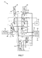
- FIG. 7 illustrates the valve of FIG. 2 responding to a manual park disengage request, in accordance with various embodiments
- FIG. 8 illustrates the valve of FIG. 2 responding to an electrical park request, in accordance with various embodiments
- FIG. 9 illustrates the valve of FIG. 2 responding to an electrical park disengage request, in accordance with various embodiments
- FIG. 10 illustrates the valve of FIG. 2 in response to an electrical request to enable emergency braking, in accordance with various embodiments
- FIG. 11 illustrates the valve of FIG. 2 in response to an electrical request to apply emergency braking, in accordance with various embodiments
- FIG. 12 illustrates the valve of FIG. 2 in response to an electrical request to exit the emergency braking, in accordance with various embodiments
- FIG. 13 illustrates the valve of FIG. 2 in response to an electrical request to release emergency braking, in accordance with various embodiments.
- FIG. 14 illustrates the valve of FIG. 2 in response to an electrical request to hold a current emergency braking pressure, and accordance with various embodiments.
- an aircraft 100 in accordance with various embodiments can include multiple landing gear including a first landing gear 110 , a second landing gear 120 , and a third landing gear 130 .
- Each landing gear may include one or more wheel assemblies.
- the third landing gear 130 includes an inner wheel assembly 132 and an outer wheel assembly 134 .
- Each landing gear 110 , 120 , 130 and/or each wheel assembly 132 , 134 of the aircraft 100 may include a braking actuator 152 , such as an aircraft brake.
- the braking actuator 152 may include multiple valves for performing various functions.
- the braking actuator 152 may include a park and emergency brake valve for controlling the braking actuator 152 for aircraft parking and for emergency braking.
- the aircraft 100 may include a hydraulic pressure source 220 and a hydraulic return 222 .
- the pressure source 220 may provide pressurized hydraulic fluid to a pressure reducing valve 150 .
- the pressure reducing valve 150 may reduce a pressure of the pressurized fluid from a first pressure value to a second pressure value.
- the hydraulic return 222 may provide hydraulic pressure relief to the pressure reducing valve 150 and a park and emergency brake valve 200 .
- the park and emergency brake valve 200 may control a braking actuator 152 which may, for example, compress rotatable discs coupled to each wheel assembly 132 , 134 .
- the park and emergency brake valve 200 may apply pressure to the braking actuator 152 to cause the braking actuator 152 to compress the rotatable discs.
- a valve may refer to a valve assembly which may include a valve and a mechanism for controlling the valve, such as a motor, a servo, or another actuator and may include an electrical component for receiving a control signal and for controlling the mechanism for controlling the valve.
- a park and emergency brake valve 200 may be used to control the braking actuator 152 .
- the park and emergency brake valve 200 may be a hydraulic system and, thus, may utilize a hydraulic fluid 250 from a pressure source 220 .
- the park and emergency brake valve 200 may be designed to engage the braking actuator 152 for parking purposes via electrical control and via manual control, and may be designed to engage the braking actuator 152 for emergency braking via electrical control.
- the park and emergency brake valve 200 may be designed to engage the braking actuator 152 for emergency braking via hydraulic control, such as replacing electric control with hydraulic control, or adding hydraulic control for emergency braking.
- the park and emergency brake valve 200 may include at least one manual park valve including a first manual park valve 202 and a second manual park valve 204 .
- Each of the manual park valves 202 , 204 may be manually controlled to provide hydraulic fluid to the braking actuator 152 for parking purposes.
- the park and emergency brake valve 200 may further include at least one electrical park valve including a first electrical park valve 206 and a second electrical park valve 208 .
- Each of the electrical park valves 206 , 208 may be electrically controlled to provide hydraulic fluid to the braking actuator 152 for parking purposes.
- the park and emergency brake valve 200 may further include at least one main valve including a first main valve 212 and a second main valve 214 .
- the park and emergency brake valve 200 may further include an electrical emergency control valve 216 and an emergency enable valve 218 .
- the electrical emergency control valve 216 may be electronically controlled, and the emergency enable valve 218 may allow hydraulic fluid to flow to the braking actuator 152 for emergency braking purposes based on actions of the electrical emergency control valve 216 .
- the park and emergency brake valve 200 may further include a controller 210 .
- the controller 210 may be positioned within the park and emergency brake valve 200 and, in various embodiments, the controller 210 may be positioned external relative to the park and emergency brake valve 200 .
- the controller may include a processor and a memory.
- the processor can be a general purpose processor, a PI controller, a digital signal processor (DSP), an application specific integrated circuit (ASIC), a field programmable gate array (FPGA), a graphical processing unit (GPU), or other programmable logic device, discrete gate or transistor logic, discrete hardware components, or any combination thereof.
- the memory may be any non-transitory memory capable of storing data. For example, the memory may store instructions to be executed by the processor.
- the controller 210 may control operation of the electrical park valves 206 , 208 and the electrical emergency control valve 216 based on data received from one or more input device, such as input devices positioned within a cockpit of the aircraft 100 of FIG. 1A
- the manual park valves 202 , 204 may be positioned on an exterior of the aircraft 100 of FIG. 1 such that a maintenance crew may park or park disengage the aircraft 100 without drawing power from the aircraft 100 .
- a pilot or copilot may park or park disengage the aircraft 100 using an input device in the cockpit.
- electrical parking is desirable as it reduces potentially complex cabling of conventional aircraft parking brakes.
- the park and emergency brake valve 200 may further include the pressure source 220 and a hydraulic return 222 .
- one or both of the pressure source 220 or the hydraulic return 222 may be positioned within the park and emergency brake valve 200 and, in various embodiments, one or both of the pressure source 220 or the hydraulic return 222 may be positioned external relative to the park and emergency brake valve 200 .
- the various valves of the park and emergency brake valve 200 may operate based on the hydraulic fluid 250 which may be received from the pressure source 220 . In response to a request for one or more valve to reduce pressure at the aircraft braking actuator 152 , pressurized fluid may be routed to the hydraulic return 222 .
- the manual park valve 301 may include an actuation lever 306 that is used to set a desired position of the manual park valve 301 . It is undesirable for the actuation lever 306 to change position in response to vibration.
- the actuation lever 306 may include a detent 302 for resisting movement of the actuation lever 306 in response to vibration.
- a spring 300 or other feature may be received by the detent 302 .
- the features of the manual park valve 301 may be used in either or both of the first manual park valve 202 or the second manual park valve 204 .
- the second manual park valve 204 may include a first control spring 350 and a second control spring 352 .
- the control springs 350 , 352 may operate together to resist movement of the second manual park valve 204 in response to vibration of the second manual park valve 204 .
- additional or alternative features may be used instead of a detent or control springs to resist movement of a manual park valve in response to vibration.
- the features of the second manual park valve 204 may be used in either or both of the first manual park valve 202 or the second manual park valve 204 .
- the park and emergency brake valve 200 may be in a steady state in response to a lack of request for parking or emergency braking.
- the park and emergency brake valve 200 may be in such state in response to an absence of a park request via the manual park valves 202 , 204 , an absence of a park request from the controller 210 , and an absence of a braking request from the controller 210 .
- the hydraulic fluid 250 from the pressure source 220 may not flow through any of the manual park valves 202 , 204 , the electrical park valves 206 , 208 , the main valves 212 , 214 , the electrical emergency control valve 216 , and the emergency enable valve 218 .
- the first main valve 212 may be configured such that hydraulic fluid may flow from the braking actuator 152 through a second main channel 468 towards the hydraulic return 222 .
- hydraulic fluid 250 from the pressure source 220 may flow through the first manual park valve 202 and the second manual park valve 204 via first manually-controlled channels 404 , 406 of the manual park valves 202 , 204 , respectively.
- the hydraulic fluid 250 may flow to a first location 408 of the first main valve 212 and a first location 410 of the second main valve 214 .
- the first main valve 212 and the second main valve 214 may actuate in response to receiving the hydraulic fluid from the manual park valves 202 , 204 .
- the main valves 212 , 214 may actuate (i.e., towards the manual park valves 202 , 204 ) in response to receiving the hydraulic fluid.
- hydraulic fluid 250 from the pressure source 220 may flow through a first main channel 412 of the first main valve 212 and a first main channel 414 of the second main valve 214 .
- the hydraulic fluid 250 that flows through the first main channels 412 , 414 may be received by the braking actuator 152 for parking.
- the controller 210 may not request parking via the electrical park valves 206 , 208 and may not request emergency braking via the electrical emergency control valve 216 . Accordingly, the hydraulic fluid 250 may not flow through the electrical park valves 206 , 208 , may not flow through the electrical emergency control valve 216 , and may not flow through the emergency enable valve 218 . Furthermore, the hydraulic fluid 250 may not flow to the hydraulic return 222 .
- the park and emergency brake valve 200 may continue to supply the pressurized hydraulic fluid 250 from the pressure source 220 to the braking actuator 152 in response to release of the actuation levers 400 , 402 . Stated differently, in response to a first reduction of the hydraulic fluid 250 flowing through the manual park valves 202 , 204 , the park and emergency brake valve 200 may continue to supply the pressurized hydraulic fluid 250 to the braking actuator 152 .
- the control springs 444 of the first manual park valve 202 and the control springs 350 , 352 of the second manual park valve 204 may cause the corresponding actuation levers 400 , 402 to return to their pre-actuation state.
- the hydraulic fluid 250 may no longer flow through the manual park valves 202 , 204 .
- the hydraulic fluid 250 may not flow through the electrical park valves 206 , 208 , the electrical emergency control valve 216 , and the emergency enable valve 218 .
- the first main valve 212 may include a magnet 440
- the second main valve 214 may include a detent 442 .
- the magnet 440 may resist movement of the first main valve 212 in response to a lack of pressurized hydraulic fluid from either of the manual park valves 202 , 204 .
- the detent 442 may resist movement of the second main valve 214 in response to a lack of pressurized hydraulic fluid from either of the manual park valves 202 , 204 .
- the detent 442 may allow the hydraulic fluid 250 to continue to flow through the second main valve 214 in response to a first reduction of hydraulic fluid 250 through the manual park valves 202 , 204 and/or in response to a second reduction of hydraulic fluid 250 through the electrical park valves 206 , 208 .
- the hydraulic fluid 250 may continue to flow from the pressure source 220 to the braking actuator 152 via the first main channels 412 , 414 .
- hydraulic fluid may not flow to the hydraulic return 222 .
- the park and emergency brake valve 200 may remain in the illustrated state until at least one of a signal is received by either electrical park valve 206 , 208 or the electrical emergency control valve 216 .
- each of the main valves 212 , 214 may include at least one of a magnet, a detent, or other feature capable of causing the corresponding main valve 212 , 214 to remain in the state in which the hydraulic fluid 250 may flow from the pressure source 220 to the braking actuator 152 via the first main channels 412 , 414 .
- the actuation levers 400 , 402 may be utilized to cause the park and emergency brake valve 200 to cause the braking actuator 152 to park disengage.
- the actuation levers 400 , 402 may be actuated in a particular manner (i.e., subjected to a second movement) that corresponds to a request to park disengage.
- the actuation levers 400 , 402 may be actuated upwards (i.e., away from the electrical park valves 206 , 208 ).
- the hydraulic fluid 250 may flow from the pressure source 220 through a second manually-controlled channel 460 of the second manual park valve 204 .
- the hydraulic fluid 250 may flow through the second manually-controlled channel 460 and be received at a second location 464 of the first main valve 212 and a second location 466 of the second main valve 214 .
- each of the main valves 212 , 214 may be actuated to change states.
- the main valves 212 , 214 may be actuated downwards (i.e., away from the manual park valves 202 , 204 ) in response to receiving the hydraulic fluid 250 from the second manually-controlled channel 460 .
- the first main valve 212 may be positioned such that the hydraulic fluid 250 from the braking actuator 152 may flow through a second main channel 468 of the first main valve 212 towards the hydraulic return 222 .
- Such flow of the hydraulic fluid 250 from the braking actuator 152 to the hydraulic return 222 reduces a pressure received by the braking actuator 152 , thus converting the braking actuator 152 from a parked state to a park disengageed state.
- hydraulic fluid 250 from the first locations 408 , 410 of the main valves 212 , 214 may flow through third manually-controlled channels 462 , 463 of the manual park valves 202 , 204 to the hydraulic return 222 .
- the magnet 440 and the detent 442 may cause the main valves 212 , 214 to remain in the state shown in FIG. 7 .
- the hydraulic fluid 250 may continue to flow from the braking actuator 152 to the hydraulic return 222 in response to release of the actuation levers 400 , 402 .
- the hydraulic fluid 250 may not flow through the second main valve 214 , the electrical park valves 206 , 208 , the electrical emergency control valve 216 , and the emergency enable valve 218 . Furthermore, the controller 210 may not control the electrical park valves 206 , 208 and the electrical emergency control valve 216 .
- the controller 210 may cause the park and emergency brake valve 200 to apply pressure to the braking actuator 152 .
- the first electrical park valve 206 includes a first actuator 500 and a second actuator 504
- the second electrical park valve 208 includes a first actuator 502 and a second actuator 506 .
- the controller 210 may be coupled to each of the actuators 500 , 502 , 504 , 506 .
- the controller 210 may control the first actuator 500 , 502 of the electrical park valves 206 , 208 .
- the controller 210 may control the actuators 500 , 502 to actuate the electrical park valves 206 , 208 into a state in which the hydraulic fluid 250 may flow through a first electrically-controlled channel 508 of the first electrical park valve 206 and a first electrically-controlled channel 510 of the second electrical park valve 208 .
- the hydraulic fluid 250 may be received at the first locations 408 , 410 of the first main valve 212 and the second main valve 214 , respectively.
- the main valves 212 , 214 may then allow the hydraulic fluid 250 flow through the first main channels 412 , 414 to the braking actuator 152 .
- hydraulic fluid may not flow through the manual park valves 202 , 204 , the electrical emergency control valve 216 , and the emergency enable valve 218 .
- the hydraulic fluid 250 may not flow to the hydraulic return 222 .
- the park and emergency brake valve 200 may remain in the state illustrated in FIG. 6 .
- pressurized fluid from the braking actuator 152 may flow through the second main channel 468 of the first main valve 212 to the hydraulic return 222 .
- pressurized hydraulic fluid from the first locations 408 , 410 may flow through third electrically-controlled channels 530 , 531 of the electrical park valves 206 , 208 , respectively, to the hydraulic return 222 .
- the first actuator 600 of the electrical emergency control valve 216 may actuate the electrical emergency control valve 216 downward (i.e., away from the manual control valves 202 , 204 ), allowing the hydraulic fluid 250 to flow through a first control channel 601 of the electrical emergency control valve 216 .
- the hydraulic fluid may flow through the first control channel 601 and the first electrically-controlled channel 508 where it may be received at the first location 408 of the first main valve 212 .
- the hydraulic fluid that flows through the first control channel 601 may be received at a first location 608 of the emergency enable valve 218 .
- the emergency enable valve 218 may be actuated to a position in which the hydraulic fluid 250 from the pressure source 220 may flow through a first enable channel 606 .
- the first main valve 212 may be actuated upwards (i.e., towards the manual park valves 202 , 204 ), allowing the hydraulic fluid that flows to the first enable channel 606 to flow through the first main channel 412 to the braking actuator 152 .
- the pressurized hydraulic fluid 250 may be received by the braking actuator 152 for braking purposes.
- the park and emergency brake valve 200 may further include a brake pressure apply orifice 604 .
- the hydraulic fluid 250 that flows through the first enable channel 606 also flows through the brake pressure apply orifice 604 .
- the brake pressure apply orifice 604 limits a flow of the hydraulic fluid through the first enable channel 606 to a relatively low flow rate. In that regard, the braking actuator 152 may become pressurized relatively slowly, reducing the likelihood of damage to tires of the aircraft 100 of FIG. 1 .
- the controller 210 may cease controlling the first actuator 500 of the first electrical park valve 206 .
- the magnet 440 may cause the first main valve 212 to remain in the state such that the hydraulic fluid 250 may continue to flow through the first main channel 412 .
- the controller 210 may cause emergency braking to continue by continuing to control the first actuator 600 of the electrical emergency control valve 216 .
- the hydraulic fluid 250 may continue to flow through the first control channel 601 , where it is received at the first location 608 of the emergency enable valve 218 .
- the emergency enable valve 218 remains in the state in which the hydraulic fluid may flow through the brake pressure apply orifice 604 through the first enable channel 606 where it may flow through the first main channel 412 to the braking actuator 152 .
- the controller 210 may control the park and emergency brake valve 200 to exit the emergency brake state.
- the controller 210 may control the second actuators 504 , 506 of the electrical park valves 206 , 208 .
- the second electrical park valve 208 may be actuated to allow the hydraulic fluid 250 from the pressure source 220 to flow through the second electrically-controlled channel 532 towards the second side 464 , 466 of the main valves 212 , 214 .
- the first main valve 212 is configured such that the hydraulic fluid may flow from the braking actuator 152 through the second main channel 468 to the hydraulic return 222 .
- the hydraulic fluid from the first locations 408 , 410 of the main valves 212 , 214 may flow through the third electrically-controlled channels 530 , 531 to the hydraulic return 222 .
- the controller 210 may also control the second actuator 602 of the electrical emergency control valve 216 .
- the electrical emergency control valve 216 may be oriented such that the hydraulic fluid 250 may no longer flow to the emergency enable valve 218 .
- control springs 700 , 702 of the emergency enable valve 218 may cause the emergency enable valve 218 to return to a state in which fluid may not flow therethrough.
- the controller 210 may control the braking actuator 152 to apply a desired amount of braking force by controlling the pressure received by the braking actuator 152 by increasing and decreasing the pressure received by the braking actuator 152 using the electrical emergency control valve 216 .
- the controller 210 may control the second actuator 602 of the electrical emergency control valve 216 to actuate such that hydraulic fluid 250 from the pressure source 220 may flow through a second control channel 752 .
- the emergency enable valve 218 may be actuated such that hydraulic fluid may flow from the braking actuator 152 through the first main channel 412 and through a second enable channel 750 of the emergency enable valve 218 to the hydraulic return 222 .
- the pressure applied by the hydraulic fluid 250 that flows through the second control channel 752 exerts a force on the emergency enable valve 218 , thus actuating the emergency enable valve 218 .
- the hydraulic fluid flowing through the second enable channel 750 to the hydraulic return 222 also flows through a brake pressure release orifice 754 .
- the brake pressure release orifice 754 limits a rate of flow of the hydraulic fluid therethrough to a predetermined flow rate.
- the brake pressure release orifice 754 allows the hydraulic fluid to flow therethrough at a rate that is greater than a rate of flow allowed by the brake pressure apply orifice 604 .
- the hydraulic fluid 250 may flow through the brake pressure apply orifice 604 at a first flow rate and may flow through the brake pressure release orifice 754 at a second flow rate that is greater than the first flow rate.
- emergency braking pressure may be continuously applied to the braking actuator 152 without control of any valve by the controller 210 .
- the controller 210 may cease controlling the electrical park valves 206 , 208 and the electrical emergency control valve 216 .
- the magnet 440 may cause the first main valve 212 to remain in a position in which fluid between the emergency enable valve 218 and the first main valve 212 may flow through the first main channel 412 to the braking actuator 152 . Accordingly, because the pressurized hydraulic fluid positioned between the emergency enable valve 218 and the braking actuator 152 does not have a route to the hydraulic return 222 , the hydraulic fluid remains pressurized, thus continuing to apply pressure to the braking actuator 152 .
- references to “one embodiment”, “an embodiment”, “an example embodiment”, etc. indicate that the embodiment described may include a particular feature, structure, or characteristic, but every embodiment may not necessarily include the particular feature, structure, or characteristic. Moreover, such phrases are not necessarily referring to the same embodiment. Further, when a particular feature, structure, or characteristic is described in connection with an embodiment, it is submitted that it is within the knowledge of one skilled in the art to affect such feature, structure, or characteristic in connection with other embodiments whether or not explicitly described. After reading the description, it will be apparent to one skilled in the relevant art(s) how to implement the disclosure in alternative embodiments.
Landscapes
- Engineering & Computer Science (AREA)
- Transportation (AREA)
- Mechanical Engineering (AREA)
- Aviation & Aerospace Engineering (AREA)
- Regulating Braking Force (AREA)
- Valves And Accessory Devices For Braking Systems (AREA)
- Braking Systems And Boosters (AREA)
Priority Applications (2)
| Application Number | Priority Date | Filing Date | Title |
|---|---|---|---|
| US15/415,610 US10093296B2 (en) | 2017-01-25 | 2017-01-25 | Electrically activated park and emergency valve with on-valve manual actuation feature |
| EP18153221.9A EP3354530B1 (de) | 2017-01-25 | 2018-01-24 | Elektrisch betätigtes park- und notventil mit on-valve-betätigungsfunktion |
Applications Claiming Priority (1)
| Application Number | Priority Date | Filing Date | Title |
|---|---|---|---|
| US15/415,610 US10093296B2 (en) | 2017-01-25 | 2017-01-25 | Electrically activated park and emergency valve with on-valve manual actuation feature |
Publications (2)
| Publication Number | Publication Date |
|---|---|
| US20180208168A1 US20180208168A1 (en) | 2018-07-26 |
| US10093296B2 true US10093296B2 (en) | 2018-10-09 |
Family
ID=61024664
Family Applications (1)
| Application Number | Title | Priority Date | Filing Date |
|---|---|---|---|
| US15/415,610 Active 2037-05-03 US10093296B2 (en) | 2017-01-25 | 2017-01-25 | Electrically activated park and emergency valve with on-valve manual actuation feature |
Country Status (2)
| Country | Link |
|---|---|
| US (1) | US10093296B2 (de) |
| EP (1) | EP3354530B1 (de) |
Cited By (1)
| Publication number | Priority date | Publication date | Assignee | Title |
|---|---|---|---|---|
| US10703464B2 (en) * | 2018-07-12 | 2020-07-07 | Goodrich Corporation | Architecture for locked wheel and antiskid performance |
Families Citing this family (5)
| Publication number | Priority date | Publication date | Assignee | Title |
|---|---|---|---|---|
| US10974709B2 (en) * | 2019-03-20 | 2021-04-13 | Goodrich Corporation | Bi-stable hydraulic control valve system |
| CN110550195A (zh) * | 2019-09-03 | 2019-12-10 | 中国航空工业集团公司西安飞机设计研究所 | 一种刹车系统 |
| CN112572392B (zh) * | 2019-09-30 | 2022-04-26 | 湖南中车智行科技有限公司 | 一种车辆制动系统及车辆制动系统控制方法 |
| DE102021122499A1 (de) * | 2021-08-31 | 2023-03-02 | Zf Cv Systems Global Gmbh | Elektropneumatisches Bremssystem, Fahrzeug, Verfahren zum Betreiben eines elektropneumatischen Bremssystems mit einer Notlöse-Ventileinheit, Verwendung einer Notlöse-Ventileinheit in einem elektropneumatischen Bremssystem |
| CN116985771B (zh) * | 2023-08-21 | 2026-04-10 | 国能神东煤炭集团有限责任公司 | 液压制动装置 |
Citations (22)
| Publication number | Priority date | Publication date | Assignee | Title |
|---|---|---|---|---|
| US4360239A (en) | 1980-01-21 | 1982-11-23 | Mcdonnell Douglas Corporation | Manual/auto brake valve |
| US4400039A (en) * | 1980-03-27 | 1983-08-23 | Kabushiki Kaisha Komatsu Seisakusho | Electro-hydraulic brake system having electric control means |
| US4456311A (en) * | 1982-03-29 | 1984-06-26 | Dresser Industries, Inc. | Hydraulic brake control and valve therefor |
| US4572585A (en) | 1982-03-05 | 1986-02-25 | Messier-Hispano-Bugatti | System for controlling a brake actuator on a vehicle, particularly an aircraft |
| US4976499A (en) | 1986-12-26 | 1990-12-11 | Messier-Hispano-Bugatti | Braking system for use when towing an aircraft on the ground |
| US5044697A (en) * | 1989-05-26 | 1991-09-03 | Crane Company | Brake valve control system |
| US5050939A (en) * | 1988-02-12 | 1991-09-24 | Atlas Copco Construction And Mining Technique Ab | Fail-safe wheel service brake system |
| US5397173A (en) | 1993-03-08 | 1995-03-14 | Messier-Bugatti | Electro-hydraulic braking system for the wheels of an aircraft |
| US6193326B1 (en) * | 1998-01-12 | 2001-02-27 | Messier-Bugatti | Apparatus for braking a set of aircraft wheels |
| US20030217899A1 (en) * | 2002-05-27 | 2003-11-27 | Komatsu Ltd. | Emergency brake apparatus for vehicle |
| US7128376B2 (en) * | 2003-05-30 | 2006-10-31 | Goodrich Corporation | Redundant architecture for brake-by-wire system |
| US20090309412A1 (en) * | 2008-06-16 | 2009-12-17 | Liebherr-Hydraulikbagger Gmbh | Traveling working machine |
| US20110108374A1 (en) | 2009-11-10 | 2011-05-12 | New York Air Brake Corporation | Automatic release hand brake control system |
| US20120133200A1 (en) * | 2010-10-12 | 2012-05-31 | Honda Patents & Technologies North America Llc | Brake system and method |
| US20120286563A1 (en) * | 2010-01-18 | 2012-11-15 | Siemens Aktiengesellschaft | Brake arrangement of a rail vehicle |
| GB2492124A (en) | 2011-06-22 | 2012-12-26 | Haldex Brake Products Ltd | Vehicle braking system having an electrically operable emergency braking override valve |
| US20140183935A1 (en) * | 2011-06-10 | 2014-07-03 | Haldex Brake Products Limited | Vehicle Braking System |
| US9108726B2 (en) | 2010-10-18 | 2015-08-18 | Honda Patents & Technologies North America, Llc | Aircraft brake system |
| US9216720B2 (en) | 2009-04-30 | 2015-12-22 | Goodrich Corporation | Differential emergency/park electric brake system |
| EP2974926A1 (de) | 2014-06-24 | 2016-01-20 | CNH Industrial Italia S.p.A. | Bremssystem für ein arbeitsfahrzeug |
| US9308900B2 (en) | 2009-02-02 | 2016-04-12 | Honeywell International Inc. | Electric parking brake control system |
| US20180162331A1 (en) * | 2016-12-09 | 2018-06-14 | Goodrich Corporation | Systems and methods for aircraft emergency and park brakes |
-
2017
- 2017-01-25 US US15/415,610 patent/US10093296B2/en active Active
-
2018
- 2018-01-24 EP EP18153221.9A patent/EP3354530B1/de active Active
Patent Citations (22)
| Publication number | Priority date | Publication date | Assignee | Title |
|---|---|---|---|---|
| US4360239A (en) | 1980-01-21 | 1982-11-23 | Mcdonnell Douglas Corporation | Manual/auto brake valve |
| US4400039A (en) * | 1980-03-27 | 1983-08-23 | Kabushiki Kaisha Komatsu Seisakusho | Electro-hydraulic brake system having electric control means |
| US4572585A (en) | 1982-03-05 | 1986-02-25 | Messier-Hispano-Bugatti | System for controlling a brake actuator on a vehicle, particularly an aircraft |
| US4456311A (en) * | 1982-03-29 | 1984-06-26 | Dresser Industries, Inc. | Hydraulic brake control and valve therefor |
| US4976499A (en) | 1986-12-26 | 1990-12-11 | Messier-Hispano-Bugatti | Braking system for use when towing an aircraft on the ground |
| US5050939A (en) * | 1988-02-12 | 1991-09-24 | Atlas Copco Construction And Mining Technique Ab | Fail-safe wheel service brake system |
| US5044697A (en) * | 1989-05-26 | 1991-09-03 | Crane Company | Brake valve control system |
| US5397173A (en) | 1993-03-08 | 1995-03-14 | Messier-Bugatti | Electro-hydraulic braking system for the wheels of an aircraft |
| US6193326B1 (en) * | 1998-01-12 | 2001-02-27 | Messier-Bugatti | Apparatus for braking a set of aircraft wheels |
| US20030217899A1 (en) * | 2002-05-27 | 2003-11-27 | Komatsu Ltd. | Emergency brake apparatus for vehicle |
| US7128376B2 (en) * | 2003-05-30 | 2006-10-31 | Goodrich Corporation | Redundant architecture for brake-by-wire system |
| US20090309412A1 (en) * | 2008-06-16 | 2009-12-17 | Liebherr-Hydraulikbagger Gmbh | Traveling working machine |
| US9308900B2 (en) | 2009-02-02 | 2016-04-12 | Honeywell International Inc. | Electric parking brake control system |
| US9216720B2 (en) | 2009-04-30 | 2015-12-22 | Goodrich Corporation | Differential emergency/park electric brake system |
| US20110108374A1 (en) | 2009-11-10 | 2011-05-12 | New York Air Brake Corporation | Automatic release hand brake control system |
| US20120286563A1 (en) * | 2010-01-18 | 2012-11-15 | Siemens Aktiengesellschaft | Brake arrangement of a rail vehicle |
| US20120133200A1 (en) * | 2010-10-12 | 2012-05-31 | Honda Patents & Technologies North America Llc | Brake system and method |
| US9108726B2 (en) | 2010-10-18 | 2015-08-18 | Honda Patents & Technologies North America, Llc | Aircraft brake system |
| US20140183935A1 (en) * | 2011-06-10 | 2014-07-03 | Haldex Brake Products Limited | Vehicle Braking System |
| GB2492124A (en) | 2011-06-22 | 2012-12-26 | Haldex Brake Products Ltd | Vehicle braking system having an electrically operable emergency braking override valve |
| EP2974926A1 (de) | 2014-06-24 | 2016-01-20 | CNH Industrial Italia S.p.A. | Bremssystem für ein arbeitsfahrzeug |
| US20180162331A1 (en) * | 2016-12-09 | 2018-06-14 | Goodrich Corporation | Systems and methods for aircraft emergency and park brakes |
Non-Patent Citations (1)
| Title |
|---|
| European Patent Office, European Search Report, Application No. 18153221.9, dated Jun. 4, 2108, 9 pages. |
Cited By (1)
| Publication number | Priority date | Publication date | Assignee | Title |
|---|---|---|---|---|
| US10703464B2 (en) * | 2018-07-12 | 2020-07-07 | Goodrich Corporation | Architecture for locked wheel and antiskid performance |
Also Published As
| Publication number | Publication date |
|---|---|
| US20180208168A1 (en) | 2018-07-26 |
| EP3354530A1 (de) | 2018-08-01 |
| EP3354530B1 (de) | 2019-09-18 |
Similar Documents
| Publication | Publication Date | Title |
|---|---|---|
| EP3354530B1 (de) | Elektrisch betätigtes park- und notventil mit on-valve-betätigungsfunktion | |
| US9387840B1 (en) | Multi-thread emergency park brake system | |
| EP3708449B1 (de) | Primäres bremsregelsystem mit abwechselnder fahrzeugsystemüberbrückung | |
| EP3501927B1 (de) | System und verfahren zur überwachung des zustands eines servoventils | |
| US12179912B2 (en) | Hybrid brake system | |
| US10703464B2 (en) | Architecture for locked wheel and antiskid performance | |
| EP3333069B1 (de) | Systeme und verfahren für flugzeugnotfall- und feststellbremsen | |
| EP3835149B1 (de) | Flugzeugbremssystem | |
| EP3357772B1 (de) | Hydraulische parkbremsanlage und verfahren | |
| US10053068B2 (en) | Systems and methods for brake control | |
| US20210086734A1 (en) | Autobrake initialization systems and methods | |
| US20180155014A1 (en) | Electrically controlled park and emergency valve assembly | |
| US10744985B2 (en) | Electro-hydrostatic brake control | |
| US10723342B2 (en) | Arbitration of multiple systems using shared components | |
| US12017758B2 (en) | Systems and methods for aircraft autobrake control | |
| EP4147923A1 (de) | Flugzeugbremssystem | |
| US9037371B2 (en) | Systems and methods for manual braking system | |
| US20190016326A1 (en) | Brake handle for emergency electric braking | |
| US20180297566A1 (en) | Brake control system with disabling features |
Legal Events
| Date | Code | Title | Description |
|---|---|---|---|
| AS | Assignment |
Owner name: GOODRICH CORPORATION, NORTH CAROLINA Free format text: ASSIGNMENT OF ASSIGNORS INTEREST;ASSIGNORS:AYICHEW, EFREM E.;CAHILL, ERIC DANIEL;BURTE, PAUL R.;SIGNING DATES FROM 20170101 TO 20170125;REEL/FRAME:041083/0651 |
|
| STCF | Information on status: patent grant |
Free format text: PATENTED CASE |
|
| MAFP | Maintenance fee payment |
Free format text: PAYMENT OF MAINTENANCE FEE, 4TH YEAR, LARGE ENTITY (ORIGINAL EVENT CODE: M1551); ENTITY STATUS OF PATENT OWNER: LARGE ENTITY Year of fee payment: 4 |
|
| MAFP | Maintenance fee payment |
Free format text: PAYMENT OF MAINTENANCE FEE, 8TH YEAR, LARGE ENTITY (ORIGINAL EVENT CODE: M1552); ENTITY STATUS OF PATENT OWNER: LARGE ENTITY Year of fee payment: 8 |